
Experimental Study on Thermal Performance of a Loop Heat Pipe with Different Working Wick Materials


Abstract

1. Introduction
2. Experimental Setups and Data Reduction
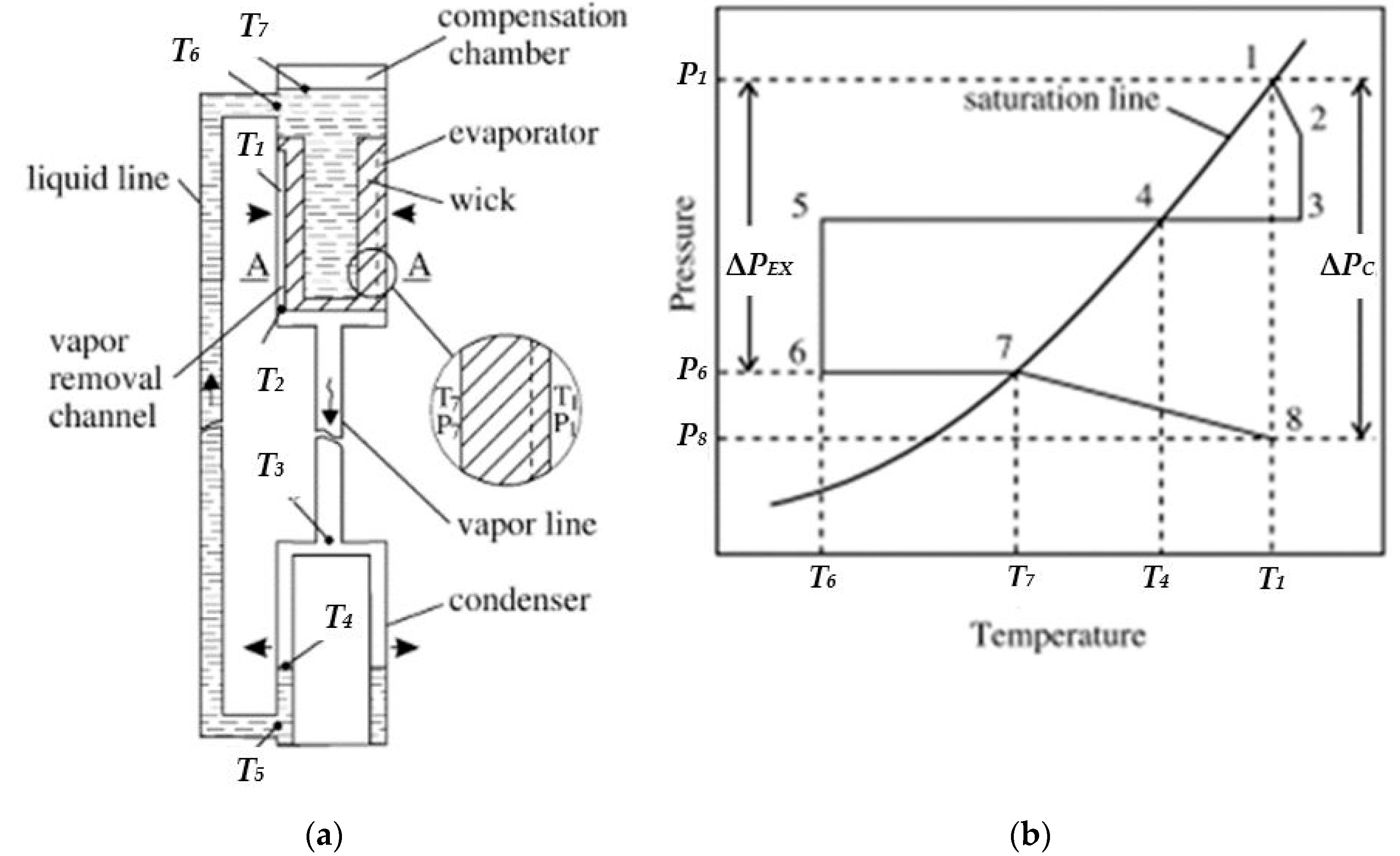
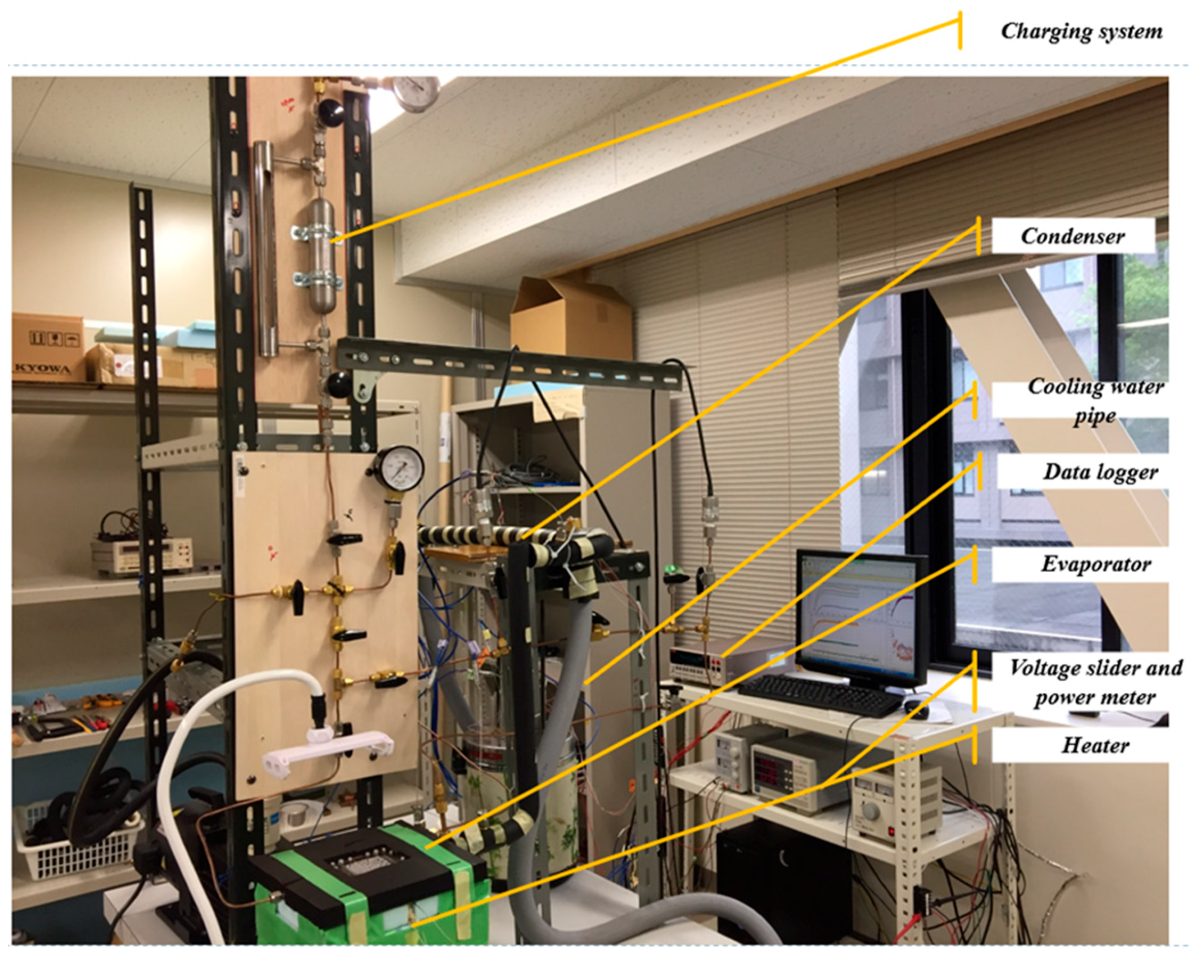
2.1. Description of Test LHP
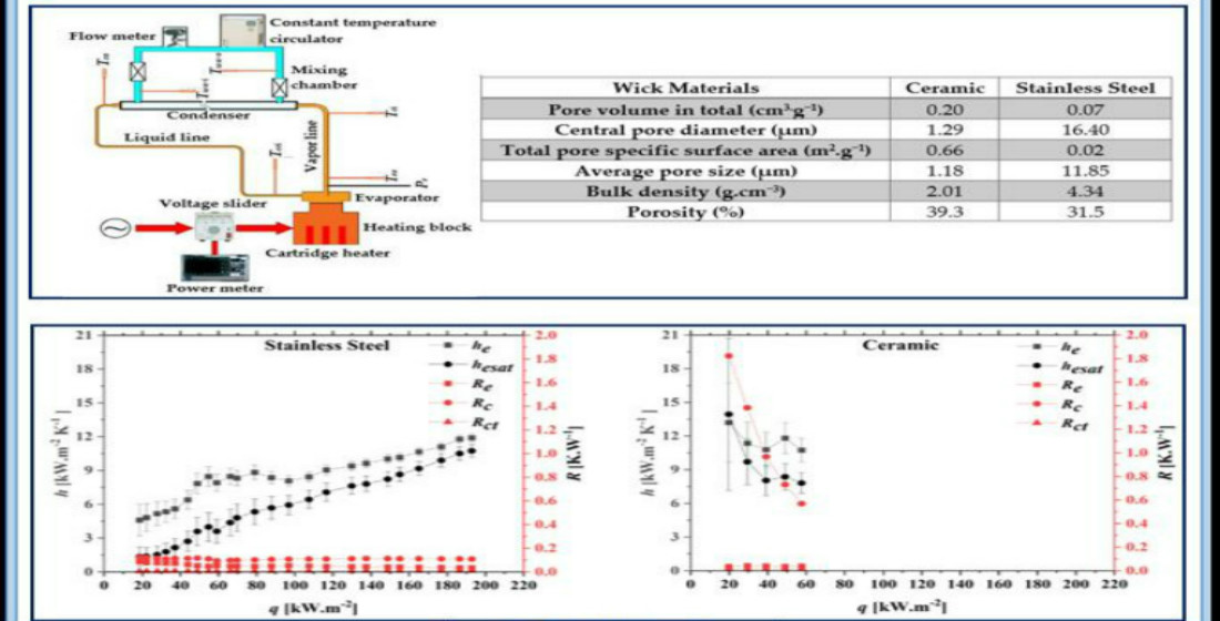
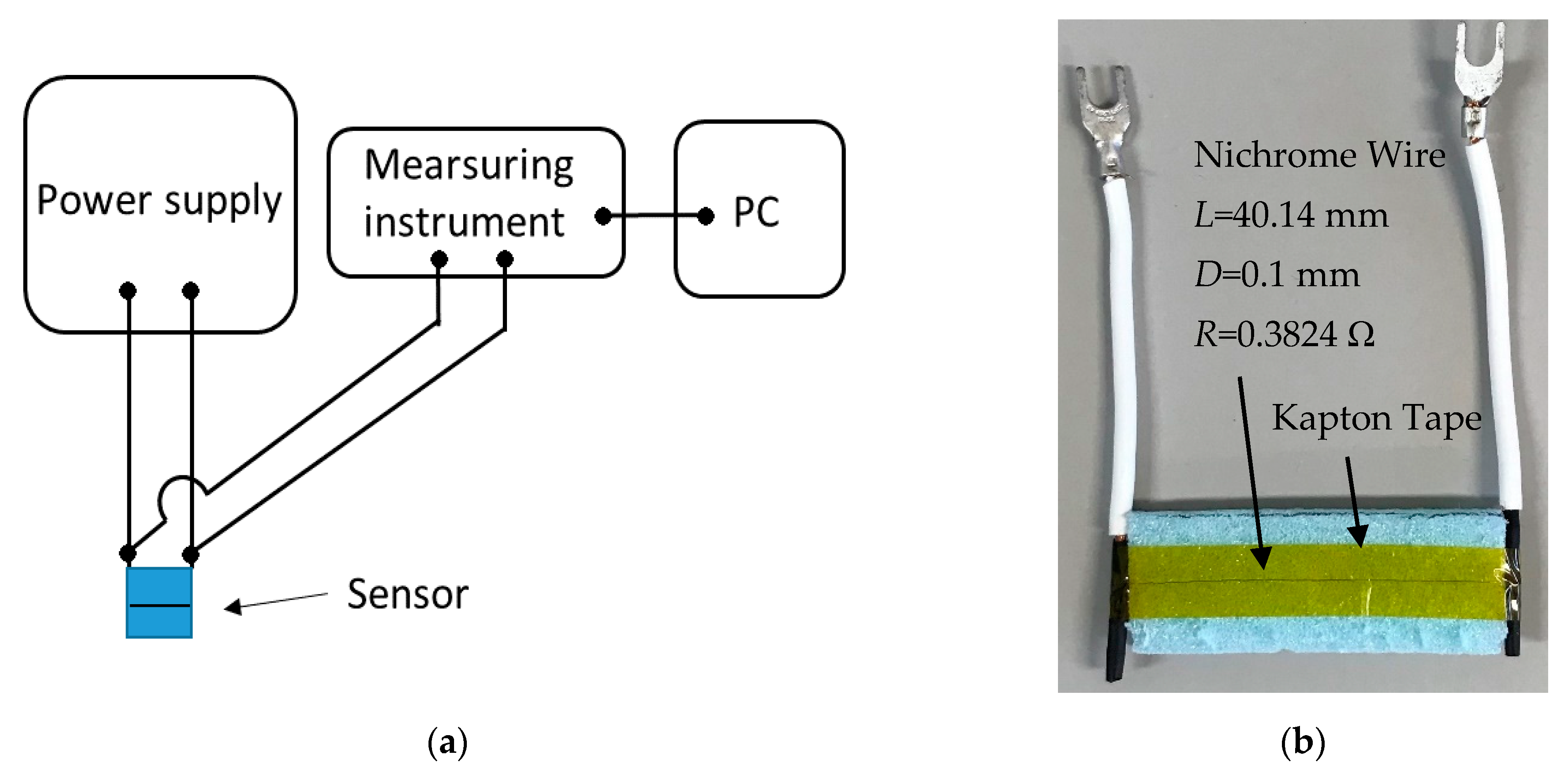
2.2. Description of the Wick’s Thermal Conductivity Measuring System
2.3. Description of Condenser
2.4. Data Reduction
3. Results and Discussion
3.1. Performance Evaluation
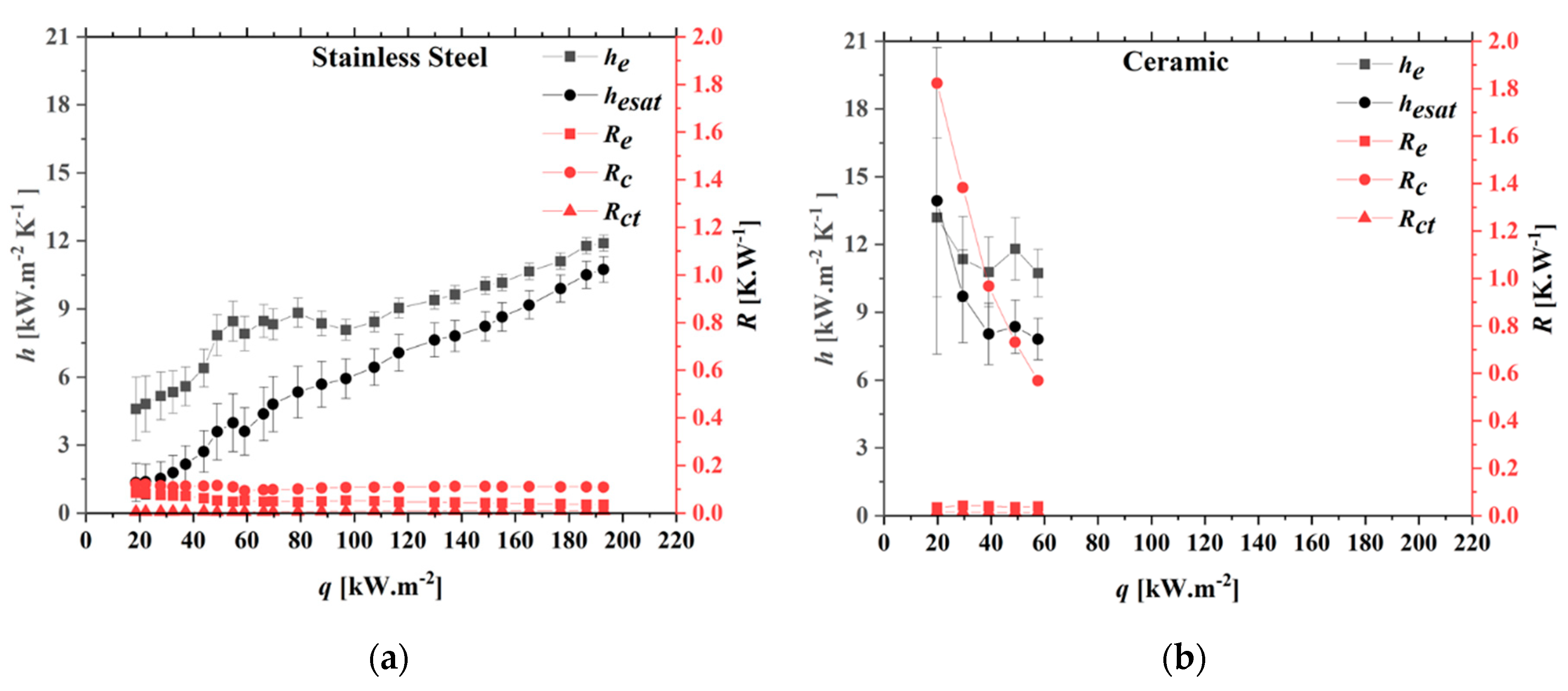
Performance of Evaporator and Condenser
4. Conclusions
Author Contributions
Funding
Institutional Review Board Statement
Informed Consent Statement
Data Availability Statement
Conflicts of Interest
Nomenclature
| Ts1 | temperature at heater surface (°C) | Tbf | fin base temperature (°C) |
| ID.OD | pipe inner.outer diameter (mm) | Tci | condenser inlet temperature (°C) |
| k | thermal conductivity of copper heating block [W·(m K)−1] | Tco | condenser outlet temperature (°C) |
| q | heat flux (kW·m−2) | Tcci | compensation chamber inlet temperature (°C) |
| Q | heat load (W) | Teo | evaporator outlet temperature (°C) |
| Re | thermal resistance of evaporator (K.W−1) | Ts2 | evaporator bottom surface temperature (°C) |
| Rc | thermal resistance of condenser (K.W−1) | Twa-i | cooling water temperature at inlet position (°C) |
| Rct | thermal contact resistance (K.W−1) | Twa-o | cooling water temperature at outlet position (°C) |
| T1 to T3 | heater temperature (°C) | δ1 | distance between the thermocouples inside heating block (m) |
| T4 | evaporator base temperature (°C) | δ2 | distance between the thermocouple T4 and the bottom surface of evaporator (m) |
| Qc | heat released from condenser (W) | CP | specific heat of cooling water [J.(kg K)−1] |
| mwa | mass flow rate of cooling water (kg·s−1) | Tesat | saturation temperature accessed from vapor pressure |
| he | heat transfer coefficient of evaporator(kW·m−2 K−1) | hesat | evaporator heat transfer coefficient calculated from saturation temperature (kW·m−2 K−1) |
| ΔT | temperature change from t = 0 (°C) | t | time (s) |
| q* | amount of heating per wire length (W·m−1) | To | initial temperature (°C) |
| Ro | initial electrical resistance (Ω) | α | temperature coefficient of resistance (°C−1) |
| V | voltage drop on thin wire (V) | L | thin wire length (mm) |
| A | area of heating block surface (m2) | λ2 | thermal conductivity of wick sample [W·(m K)−1] |
| I | electric current (I) | λ1 | thermal conductivity of insulator [W·(m K)−1] |
| heat transfer rate per unit heating block’s surface area (kW·m−2) |
References
- Maydanik, Y.F. Loop heat pipes. Appl. Therm. Eng. 2005, 25, 635–657. [Google Scholar] [CrossRef]
- Zhou, W.; Ling, W.; Duan, L.; Hui, K. Development and tests of loop heat pipe with multi-layer metal foams as wick structure. Appl. Therm. Eng. 2016, 94, 324–330. [Google Scholar] [CrossRef]
- Siedel, B.; Sartre, V.; Lefèvre, F. Numerical investigation of the thermo hydraulic behaviour of a complete loop heat pipe. Appl. Therm. Eng. 2013, 61, 541–553. [Google Scholar] [CrossRef]
- Maydanik, Y.; Fershtater, Y.G.; Pastukhov, V.G. Loop Heat Pipes: Development, Investigation and Elements of Engineering Calculations; Technical Report; Ural Division of the USSR Academy of Sciences: Moscow, Russia, 1989. [Google Scholar]
- Hoang, T.T.; O’Connell, T.A.; Ku, J.; Butler, C.D.; Swanson, T.D. Miniature loop heat pipes for electronic cooling. In Proceedings of the ASME 2003 International Electronic Packaging Technical Conference and Exhibition, Maui, HI, USA, 6–11 July 2003; pp. 517–525. [Google Scholar]
- Kondou, C.; Umemoto, S.; Koyama, S.; Mitooka, Y. Improving the heat dissipation performance of a looped thermosyphon using low-GWP volatile fluids R1234ze(Z) and R1234ze(E) with a super-hydrophilic boiling surface. Appl. Therm. Eng. 2017, 118, 147–158. [Google Scholar] [CrossRef]
- Santos, P.H.; Bazzo, E.; Becker, S.; Kulenovic, R.; Mertz, R. Development of LHPs with ceramic wick. Appl. Therm. Eng. 2010, 30, 1784–1789. [Google Scholar] [CrossRef]
- Canti, G.; Celata, G.P.; Cumo, M.; Furrer, M. Thermal hydraulic characterization of stainless steel wicks for heat pipe applications. Rev. Gén. Therm. 1998, 37, 5–16. [Google Scholar] [CrossRef]
- Ji, X.; Wang, Y.; Xu, J.; Huang, Y. Experimental study of heat transfer and start-up of loop heat pipe with multiscale porous wicks. Appl. Therm. Eng. 2017, 117, 782–798. [Google Scholar] [CrossRef]
- Maydanik, Y.; Chernysheva, M.; Pastukhov, V.G. Review: Loop heat pipes with flat evaporators. Appl. Therm. Eng. 2014, 67, 294–307. [Google Scholar] [CrossRef]
- Fukushima, K.; Nagano, H. International Journal of Heat and Mass Transfer New evaporator structure for micro loop heat pipes. Int. J. Heat Mass Transf. 2017, 106, 1327–1334. [Google Scholar] [CrossRef]
- Nishikawara, M.; Nagano, H. International Journal of Heat and Mass Transfer Optimization of wick shape in a loop heat pipe for high heat transfer. Int. J. Heat Mass Transf. 2017, 104, 1083–1089. [Google Scholar] [CrossRef]
- Xu, J.; Ji, X.; Yang, W.; Zhao, Z. Modulated porous wick evaporator for loop heat pipes: Experiment. Int. J. Heat Mass Transf. 2014, 72, 163–176. [Google Scholar] [CrossRef]
- Wu, S.; Wang, D.; Gao, J.; Huang, Z.; Chen, Y. Effect of the number of grooves on a wick’s surface on the heat transfer performance of loop heat pipe. Appl. Therm. Eng. 2014, 71, 371–377. [Google Scholar] [CrossRef]
- Choi, J.; Sung, B.; Kim, C.; Borca-Tasciuc, D.-A. Interface engineering to enhance thermal contact conductance of evaporators in miniature loop heat pipe systems. Appl. Therm. Eng. 2013, 60, 371–378. [Google Scholar] [CrossRef]
- Singh, R.; Akbarzadeh, A.; Mochizuki, M. Operational characteristics of a miniature loop heat pipe with flat evaporator. Int. J. Therm. Sci. 2008, 47, 1504–1515. [Google Scholar] [CrossRef]
- Chernysheva, M.; Yushakova, S.; Maydanik, Y. Copper–water loop heat pipes for energy-efficient cooling systems of supercomputers. Energy 2014, 69, 534–542. [Google Scholar] [CrossRef]
- Zhou, G.; Li, J.; Lv, L. An ultra-thin miniature loop heat pipe cooler for mobile electronics. Appl. Therm. Eng. 2016, 109, 514–523. [Google Scholar] [CrossRef]
- Shioga, T.; Mizuno, Y. Micro loop heat pipe for mobile electronics applications. In Proceedings of the 2015 31st Thermal Measurement, Modeling & Management Symposium (SEMI-THERM), San Jose, CA, USA, 15–19 March 2015; pp. 50–55. [Google Scholar]
- Li, J.; Lin, F.; Wang, D.; Tian, W. A loop-heat-pipe heat sink with parallel condensers for high-power integrated LED chips. Appl. Therm. Eng. 2013, 56, 18–26. [Google Scholar] [CrossRef]
- Moffat, R.J. Describing the uncertainties in experimental results. Exp. Therm. Fluid Sci. 1988, 1, 3–17. [Google Scholar] [CrossRef]
- Takekoshi, E.; Imura, S.; Hirasawa, Y.; Takenaka, T. Method for Measuring Thermal Conductivity of Solids by Transient Thin Wire heating Comparison Method (Edition. B); Japan Society of Mechanical Engineers: Tokyo, Japan, 1981; Volume 47, pp. 1307–1316. [Google Scholar] [CrossRef]
- Ebrahimi, K.; Jones, G.F.; Fleischer, A.S. A review of data center cooling technology, operating conditions and the corresponding low-grade waste heat recovery opportunities. Renew. Sustain. Energy Rev. 2014, 31, 622–638. [Google Scholar] [CrossRef]
- Nourzadeh, N.; Shadizadeh, S.R.; Manshad, A.K. Determination of pore size distribution profile along wellbore: Using repeat formation tester. J. Pet. Explor. Prod. Technol. 2017, 7, 621–626. [Google Scholar] [CrossRef]
- Saga Ceramics Research Laboratory. Available online: https://www.scrl.gr.jp/main/ (accessed on 28 November 2019).
- Meléndez, E.; Reyes, R. The pool boiling heat transfer enhancement from experiments with binary mixtures and porous heating covers. Exp. Therm. Fluid Sci. 2006, 30, 185–192. [Google Scholar] [CrossRef]


| No. | Modern | Thermal Power Design (W) | Case Dimensions (mm × mm) | Heat Flux (W/cm2) |
|---|---|---|---|---|
| 1 | Core i7 5960X | 140 | 52.5 × 45 | 5.9 |
| 2 | Core i7 5930K | 140 | 52.5 × 45 | 5.9 |
| 3 | Core i7 4960X | 130 | 52.5 × 45 | 5.48 |
| 4 | Core i7 4930X | 130 | 52.5 × 45 | 5.48 |
| 6 | Core i7 3790X | 150 | 52.5 × 45 | 6.3 |
| 7 | Xeon E7 8891 v3 | 165 | 52 × 45 | 7.05 |
| 8 | Xeon E7 8880 v3 | 150 | 52 × 45 | 6.41 |
| 9 | Xeon E7 8890 v2 | 155 | 52 × 45 | 6.62 |
| 10 | Itanium 9300 | 185/155/130 | 48.5 × 40.25 | 9.47/7.94/6.66 |
| 11 | Itanium 9500 | 170/130 | 48.5 × 40.25 | 8.71/6.66 |
| No. | References | Specifications of LHPs from the Literature | Objects and Results |
|---|---|---|---|
| 1. | K. Fukushima—2017 [11] Keywords: Capillary force, heat transport, LHP, porous PTFE | Flat—rectangular evaporator New-fashioned flat evaporator structure, micro-LHP (Evaporator 20 × 10 × 3 mm, 200 mm in length transport line) Porous polytetrafluorethylene wick 17 × 9 × 2 mm (PTFE) (50%, 2.2 μm, 6.48 × 10⁻¹⁴ m2, 0.25 W/m·K) Working fluid: ethanol. | Objects: A wick with a liquid core is proposed. An experimental and computational investigation was conducted. The temperature distribution inside the evaporator and the heat load’s break down from the mathematical model are obtained. Results: Minimum RLHP is 1.2 K/W and maximum Q = 11 W, from the experiment.   |
| 2. | M. Nishikawara—2017 [12] Keywords: Capillary evaporator, capillary pumped loop, evaporator HTC, LHP, optimized wick shape, 3-phase contact line | PTFE wick (bulk thermal conductivity = 0.25 W/m·K). Stainless steel case (k = 16 W/m·K) Machined widths (minimum): 0.3 (circumferential groove) and 0.4 mm (axial groove)  Increasing axial grooves will reduce the number of circumferential grooves. Three wicks were fabricated for experimental examination: Ltri = 3150/m (4 axial × 71 circumferential) Ltri = 2630/m (16 axial × 56 circumferential) Classical wick with only 16 axial grooves and 1 mm width of the groove | Objects: It presents a method for the wick shape optimization via calculation and experiment. Using only the three-phase contact line’s length, the hevap is maximized (q = 2 W/cm2). Effects of the case, wick material, and the working fluid, are discussed. Results: The effect of the three-phase contact line (TPCL) on the groove pressure loss (by calculation) is shown. Comparison between evaporator heat-transfer coefficient (HTC) obtained using Equation (9) and that obtained through the experiments (ethanol) is presented.   The heat transport’s contribution at TPCL was estimated at 0.87 when fitting to experiment results and 0.63 in simulation. Comparison of various working fluids and wick materials, htri increased with wick’s thermal conductivity. The value of htri was higher for ammonia due to the changes in interfacial HTC. |
| 3. | Jinliang Xu—2014 [13] Keywords: LHP, evaporator, heat transfer, modulated porous wick | Flat-disk shape evaporator. Tilt angles: −90°, −60°, −30°, 0°, 90° (“−”: antigravity) Forced convective air cooling (Ta = 22 to 24 °C) Water as working fluid There are three layers of porous materials, primary layer (as shown in table), secondary copper table (2 mm–149μm), and third absorbent wool layer (2 mm–rpore = 20 μm) Evaporator: ϕ80 × 10 (without CC thickness); Aheating = 5 cm2 Vapor line: ID6/OD8 × 550 mm Liquid line: ID6/OD8 × 300 mm Condenser: 130 × 130 × 25 CR = 38.5%, 51.3%; 64.1%, 64.1%, 76.9% Sintering process: oven temperature 900 °C for 4 h. | Objects: It is to enhance heat transfer of pool boiling using the modulated porous wick sintered on the heater wall. Three types of evaporators: MWE (microchannel/wick evaporator), MME (modulated monoporous wick evaporator), and MBE (modulated biporous wick evaporator) were fabricated. Results: MBE LHP reduces the startup time and achieves more stable operation than MWE. At heat flux of 40 W/cm2 (heater heat flux), the MBE LHP can operate when Tc is around 63 °C; (Rt = 0.12 K/W) Optimum CR = 51.3%. Operation antigravity condition is better than others with the MBE LHP’s proper design. Best fin’s geometric parameters: h = 1.5 mm; p = 1.5 mm; w = 3 mm; best particle size: 88 μm |
| 4. | S.C. Wu—2014 [14] Keywords: Wick structure, LHP, evaporator area, grooves | LHP with cylindrical stainless-steel evaporator (ϕ16 × 65) Water cooling Wick material: nickel (ID/OD = 9/12.5); largest rpore = 1.9 − 2.5 μm; K = 1.3 − 3.25 × 10⁻¹³ m2, porosity: 63–67%. Vapor line: ID5/OD6 × 470 Liquid line: ID4.5/OD6 × 585 Condenser: ID5/OD6.4 × 800 Ammonia as working fluid. | Objects: The effects of increasing the number of grooves on a wick’s surface on LHP performance were investigated. Results: The wick with 16-groove was quickly damage. The other wicks have similar properties, such as porosity, pore radius, K. Sintering condition: 45 min at 600 °C. Increasing the groove number increases the LHP’s performance (Q = 500 W, Rt = 0.14 K/W). An optimal number of grooves fabricated on the wick surface is presented. |
| 5. | Jeehoon Choi—2013 [15] Keywords: Miniature LHP, evaporator, sintering, contact conductance, thermal resistance | Flat-disk shape evaporator. Wick material = Nickel (ϕ42 × 3), particles size: 3 μm, Pcapillary= 401. kPa, K = 0.99·10−11 m2, porosity = 64%, keff = 9 W/K·m CC: stainless-steel (ϕ46 × 7) Vapor line: ID4.95/OD6.35 × 250 (made by copper) Liquid line: ID4.95/OD6.35 × 300 (made by stainless-steel) Forced convective air cooling Working fluid: water Horizontal orientation Heater surface area: 30 × 30 mm2 | Objects: For fabricating the LHP’s evaporator, a low-cost sintering method is explored. The porous material partially fills the vapor collection channel embedded in the evaporator’s base; two evaporators were fabricated. A sintering procedure is used to fabricate the evaporator shown in Figure (b). It is presented in Section 2.2 of the paper. Results: The startup of LHP with the second evaporator was shorter in time and more stable than one with the traditional LHP. By using the evaporator with the interpenetrated wick, the temperature on the CC reduced significantly which is 34 °C. Traditional LHP operated at 30–165 W; 80–141 °C; 1.81–0.71 K/W LHP using interpenetrated wick/base plate: 30–180 W; 47–102 °C; 0.76–0.43 K/W The lower temperature of the CC was due to the design of the second evaporator. It helped the wick and evaporator base contact excellently. It reduced heat loss to the CC through the evaporator’s wall. |
| 6. | Randeep Singh—2008 [16] Keywords: LHP, heat transfer, thermal performance, miniature LHP, flat evaporator, thermal control | Miniature LHP using flat disk-shaped copper evaporator (ϕ30 × 10 mm) Working fluid: water Nickel wick (thickness = 3 mm, rpore = 3–5 μm; porosity: 75%) Condenser using Air forced cooling (Ta = 22 ± 2 °C) Copper Vapor line: ϕ2 × 150 mm Copper Liquid line: ϕ2 × 290 mm Heater surface area: 25 × 25 mm Condenser: ϕ2 × 50 mm | Objects: For the thermal control of small electronic equipment, it addresses the thermal characteristics of mLHP using a flat disk-shaped evaporator.  Results: Startup condition at different heat loads, Q = 5–70 W, RmLHP = 5.66–0.17 K/W. The evaporator wall’s temperature was lower than 100 °C. Oscillating behavior was found when Q was between 10 and 20 W. This oscillation occured due to the fluctuation of heat loss from the evaporator to the CC and the subcooled liquid temperature. |
| 7. | M.A. Chernysheva—2014 [17] Keywords: LHP, supercomputer, cooling system, operating temperature, thermal resistance | Flat-oval evaporator (longitudinal replenishment evaporator) 80 × 42 × 7 mm, Aactive = 32 × 42 mm2 12 Vapor grooves ϕ1.8 × 33 Copper wick (porosity 43%, rpore = 27 μm) Vapor line: (1) ID4/OD5 × 305 mm, (2) ID3/OD4 × 305 mm Liquid line: ID3/OD4 × 810 mm Condenser: ID4/OD5 × 160 mm | Objects: A cooling system with an LHP for a supercomputer’s thermal control is presented. Copper loop heat pipes with different vapor pipe IDs (4 and 3 mm each) were fabricated. The test was carried out with a heat load from 20 to 600 W during the cooling water’s temperature was changed from 20 to 80 °C.  Results: LHP’s operating temperature varied slightly when the condenser cooling temperature changed in the range below 40 °C (called as variable conductance mode). It is more applicable to use copper-water LHPs when cooling temperatures of condenser is above 50 °C. |
| 8. | Guohui Zhou—2016 [18] Keywords: Miniature LHP, ultrathin, thermal resistance, mobile electronics | Flat evaporator (thickness, δ = 1.2 mm), vapor line, liquid line, and condenser line (δ = 1 mm) Evaporator: 60 × 23 × 1.2 mm Aactive: 15 × 9 mm Primary porous material (inside evaporator): sintered from 10 layers of 500 mesh copper wire mesh (50 × 21 × 0.8 mm) (porosity: 65.2%) Secondary wick (in liquid line) sintered from 4 layers of 150 mesh copper wire mesh (δ = 0.43 mm) Liquid line: 105 mm, vapor line: 105 mm. Condenser: 125 mm (Natural cooling) LHP’s inclination: horizontal, anti-, and assisted gravity. Water as working fluid | Objects: mLHP for mobile electronics. Results: Startup of LHP happened at 2 W with evaporator temperature 43.9 °C. When Q is at 11 W, RLHP = 0.11 K/W There is no noticeably different performance with different orientations. For cooling mobile electronics: a tablet or smartphone, this mLHP achieves a promising thermal management solution. |
| 9. | Takeshi Shioga—2015 [19] Keywords: Micro LHP, thermal resistance, heat leak, operation orientation | Micro loop heat pipe Chemical-etching and diffusion bonding process for fabrication Evaporator: 20 × 17 × 0.6 mm Vapor line: (1) 5.6 × 0.4 and (2) 1 × 75 mm in length Liquid line 4 × 0.4 × 120 mm Condenser (1) 5.6 × 0.4 and (2) 1 × 110 mm in length Working fluid: water | Objects: This micro LHP was fabricated for mobile electronic devices. The effect of vapor and condenser thickness on μLHP performance was investigated.  Results: The μLHP could not operate with vapor line and condenser line thickness at 0.4 mm. When Q is at 5 W, RLHP = 0.8 K/W, Tevaporator = 50.5 °C. When Q = 15 W, RLHP = 0.32 K/W. Heat loss was estimated at around 11%. Based on the operating orientation, the LHP’s performance was slightly changed. |
| 10. | Ji Li—2013 [20] Keywords: LED cooling, LHP, parallel condensers, thermal resistance | Evaporator: 30 × 30 × 15 (in mm). Gravity assisted LHP Connecting line: ID 5 mm Wick material is copper (porosity 50%, rpore = 65 μm, K = 6 ×10⁻¹¹ m2) A Heater = 25 × 25 mm2 Condenser size: 120 × 80 × 50 mm | Objects: The investigation of copper-water LHP using dual parallel condensers was conducted primarily for LED illumination applications with high-power. Results: At Q = 300 W, the value of R is 0.4 °C/W; with Tair = 15 °C, Q = 0–100 W, Tjunction < 75 °C. At low heat loads, the condenser’s unpredictable nonuniform performance caused the unstable behavior of the LHP. |
| Evaporator Body | Values |
|---|---|
| Material | Copper |
| Length (mm) | 80 |
| Width (mm) | 70 |
| Height (mm) | 24.5 |
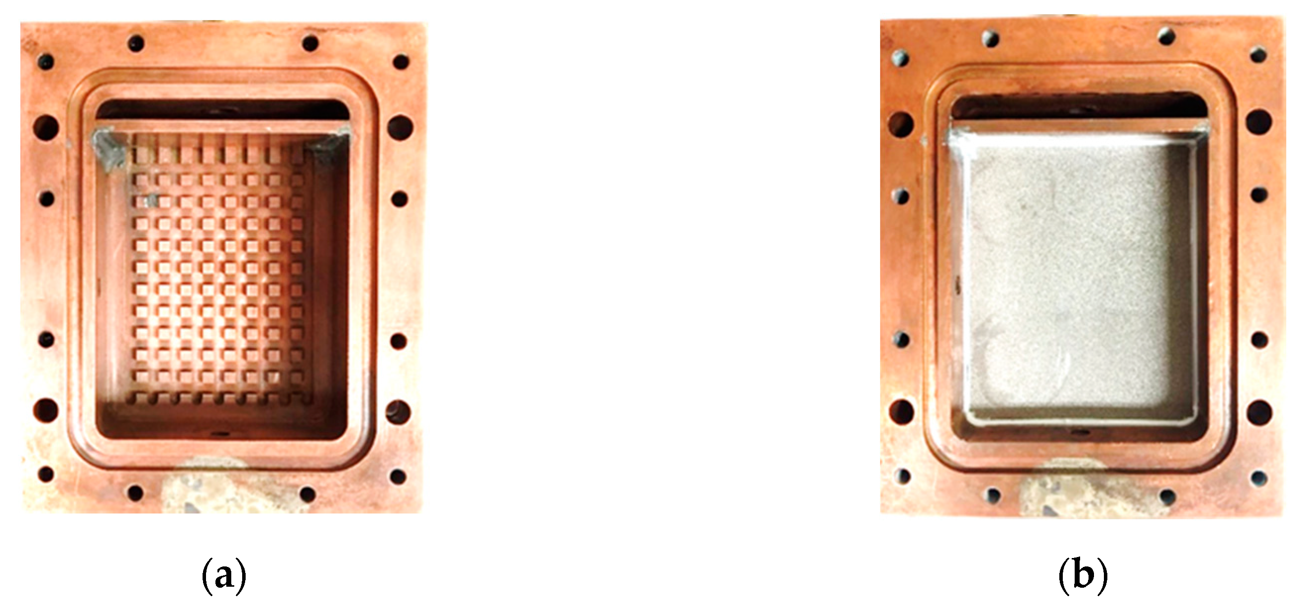
| Active area (mm2) | 60 × 45 |
| Fin geometry | |
| Cross area (mm2) | 2 × 2 |
| Height (mm) | 1.5 |
| Fin pitch (mm) | 4 |
| Wick structure | |
| Material | Stainless steel |
| Bulk volume (mm3) | 50 × 41 × 5 |
| Material | Ceramic |
| Bulk volume (mm3) | 50 × 41 × 5 |
| Vapor line | |
| OD/ID (mm) | 6.35/4.35 |
| Length (mm) | 800 |
| Condenser line | |
| OD/ID (mm) | 6.35/4.35 |
| Length (mm) | 600 |
| Liquid line | |
| OD/ID (mm) | 3.2/1.7 |
| Length (mm) | 1300 |
| Working fluid | |
| Water | |
| Amount (mL) | 33 |
| Parameters | Uncertainty |
|---|---|
| T1, T2, T3 | 0.06 °C |
| T4 | 0.07 °C |
| Teo | 0.06 °C |
| Tci | 0.06 °C |
| Tco, Tcci | 0.1 °C |
| Twa-i | 0.1 °C |
| Twa-o | 0.06 °C |
| Pressure transducer | 1.5 kPa |
| Mass flow meter | 0.18% of reading |
| Present Study | Value from References | ||
|---|---|---|---|
| Wick | λ2 [W (m K)−1] | Wick | λ2 [W (m K)−1] |
| Stainless Steel | 6.4 | SP-Sintered [8] | 11.87 |
| Ceramic | 3.5 | Ceramic [7] | 4 |
| Parameters | Inner Tube | Outer Tube |
|---|---|---|
| Material | Smooth Copper tube | Poly-carbonated resin |
| Length, mm | 600 mm | 600 mm |
| OD/ID, mm | 6.35/4.35 | 13/9 |
| Wick Materials | Ceramic | Stainless Steel |
|---|---|---|
| Pore volume in total (cm3·g−1) | 0.20 | 0.07 |
| Central pore diameter (μm) | 1.29 | 16.40 |
| Total pore specific surface area (m2·g−1) | 0.66 | 0.02 |
| Average pore size (μm) | 1.18 | 11.85 |
| Bulk density (g.cm−3) | 2.01 | 4.34 |
| Porosity (%) | 39.3 | 31.5 |
| Q | q | δ(q) | he | δ(he) | hesat | δ(hesat) |
|---|---|---|---|---|---|---|
| W | W/m2 | % | W/(m2‧K) | % | W/(m2‧K) | % |
| 50.22 | 18,598.44 | 30.42 | 4592.67 | 30.46 | 1345.93 | 62.64 |
| 100.29 | 37,299.05 | 15.17 | 5588.10 | 15.25 | 2150.30 | 37.71 |
| 147.91 | 54,451.96 | 10.39 | 8458.43 | 10.39 | 3984.10 | 32.14 |
| 188.17 | 69,832.60 | 8.10 | 8323.83 | 8.12 | 4804.16 | 25.30 |
| 237.16 | 87,723.91 | 6.45 | 8368.00 | 6.43 | 5676.28 | 17.73 |
| 290.03 | 107,645.92 | 5.26 | 8427.34 | 5.14 | 6428.54 | 12.52 |
| 350.72 | 129,896.27 | 4.35 | 9388.90 | 4.31 | 7633.87 | 9.80 |
| 401.67 | 148,767.07 | 3.80 | 10,023.39 | 3.77 | 8228.43 | 7.74 |
| 445.87 | 165,137.27 | 3.43 | 10,651.51 | 3.46 | 9177.51 | 6.74 |
| 503.47 | 186,469.50 | 3.03 | 11,785.25 | 3.08 | 10,499.12 | 5.67 |
| 520.70 | 192,826.71 | 2.93 | 11,900.59 | 2.99 | 10,742.33 | 5.26 |
| Q | q | δ(q) | he | δ(he) | hesat | δ(hesat) |
|---|---|---|---|---|---|---|
| W | W/m2 | % | W/(m2‧K) | % | W/(m2‧K) | % |
| 53.41 | 19,782.71 | 28.59 | 13,195.93 | 26.67 | 13,932.62 | 48.68 |
| 79.59 | 29,477.46 | 19.19 | 11,352.25 | 16.61 | 9709.18 | 21.12 |
| 105.72 | 39,154.18 | 14.45 | 10,783.11 | 14.27 | 8046.37 | 16.92 |
| 132.38 | 49,028.99 | 11.54 | 11,805.62 | 11.73 | 8359.43 | 14.03 |
| 155.45 | 57,574.38 | 9.83 | 10,737.34 | 9.87 | 7810.08 | 11.71 |
Publisher’s Note: MDPI stays neutral with regard to jurisdictional claims in published maps and institutional affiliations. |
© 2021 by the authors. Licensee MDPI, Basel, Switzerland. This article is an open access article distributed under the terms and conditions of the Creative Commons Attribution (CC BY) license (https://creativecommons.org/licenses/by/4.0/).
Share and Cite
Htoo, K.Z.; Huynh, P.H.; Kariya, K.; Miyara, A. Experimental Study on Thermal Performance of a Loop Heat Pipe with Different Working Wick Materials. Energies 2021, 14, 2453. https://doi.org/10.3390/en14092453
Htoo KZ, Huynh PH, Kariya K, Miyara A. Experimental Study on Thermal Performance of a Loop Heat Pipe with Different Working Wick Materials. Energies. 2021; 14(9):2453. https://doi.org/10.3390/en14092453
Chicago/Turabian StyleHtoo, Kyaw Zin, Phuoc Hien Huynh, Keishi Kariya, and Akio Miyara. 2021. "Experimental Study on Thermal Performance of a Loop Heat Pipe with Different Working Wick Materials" Energies 14, no. 9: 2453. https://doi.org/10.3390/en14092453
APA StyleHtoo, K. Z., Huynh, P. H., Kariya, K., & Miyara, A. (2021). Experimental Study on Thermal Performance of a Loop Heat Pipe with Different Working Wick Materials. Energies, 14(9), 2453. https://doi.org/10.3390/en14092453