Article

Semi-Analytical Solution to Assess CO2 Leakage in the Subsurface through Abandoned Wells

1
Physical Science and Engineering Division, King Abdullah University of Science and Technology (KAUST), Thuwal 23955, Saudi Arabia
2
Institut Terre et Environnement de Strasbourg, Université de Strasbourg, CNRS, ENGEES, UMR 7063, 67081 Strasbourg, France
*
Author to whom correspondence should be addressed.
Energies 2021, 14(9), 2452; https://doi.org/10.3390/en14092452
Submission received: 26 February 2021 / Revised: 9 April 2021 / Accepted: 12 April 2021 / Published: 25 April 2021
(This article belongs to the Special Issue Modeling Multiphase Flow and Reactive Transport in Porous Media)

Abstract

:
Geological carbon storage is an effective method capable of reducing carbon dioxide (CO2) emissions at significant scales. Subsurface reservoirs with sealing caprocks can provide long-term containment for the injected fluid. Nevertheless, CO2 leakage is a major concern. The presence of abandoned wells penetrating the reservoir caprock may cause leakage flow-paths for CO2 to the overburden. Assessment of time-varying leaky wells is a need. In this paper, we propose a new semi-analytical approach based on pressure-transient analysis to model the behavior of CO2 leakage and corresponding pressure distribution within the storage site and the overburden. Current methods assume instantaneous leakage of CO2 occurring with injection, which is not realistic. In this work, we employ the superposition in time and space to solve the diffusivity equation in 2D radial flow to approximate the transient pressure in the reservoirs. Fluid and rock compressibilities are taken into consideration, which allow calculating the breakthrough time and the leakage rate of CO2 to the overburden accurately. We use numerical simulations to verify the proposed time-dependent semi-analytical solution. The results show good agreement in both pressure and leakage rates. Sensitivity analysis is then conducted to assess different CO2 leakage scenarios to the overburden. The developed semi-analytical solution provides a new simple and practical approach to assess the potential of CO2 leakage outside the storage site. This approach is an alternative to numerical methods when detailed simulations are not feasible. Furthermore, the proposed solution can also be used to verify numerical codes, which often exhibit numerical artifacts.

1. Introduction

In recent decades, the global warming problem has raised major challenges. The impact of rapid temperature change is already visible in extreme weather events and sea-level rise, among others [1,2,3,4,5]. Reducing the greenhouse gas (GHG) concentration in the atmosphere is therefore urgent. Among all greenhouse gases, carbon dioxide (CO2) is the main elementcontributing to the Earth’s rising temperature [6,7]. Carbon capture and storage (CCS) technologies are expected to reduce emissions from fossil fuels significantly. Carbon storage in geological formations is a promising method to store CO2 in underground reservoirs at significant scales [8]. Subsurface reservoirs with sealing caprocks can provide long-term containment for the CO2. There are currently around 60 large-scale CCS facilities under operation or development worldwide, resulting in 30 million metric tons (Mt) of CO2 captured and stored per year in 2020 [9]. The storage potential of CCS is different for various underground formations like saline aquifers and depleted oil and gas reservoirs [10,11,12]. Subsurface reservoirs with production history could be preferred because of their cost-effectiveness in using existing infrastructure and knowledge about the subsurface geology. However, natural and artificial permeable patterns, such as fractures and existing wells, may cause fluid leakage to the surrounding formation [13,14,15,16,17,18,19]. The related well integrity problems have been widely investigated for existing injection wells and abandoned wells in different CCS projects [20,21,22]. Among them, abandoned wells require careful attention, as they could penetrate the caprock, creating potential leakage flow-paths to the overburden. For instance, improper well abandonment may create permeable channels through the borehole, space between casing and cement, or fractures in the cement, which induce hydrodynamic communications across the penetrated geological layers [23,24,25,26,27]. Fluid leakage across geological layers is difficult to quantify because of the lack of subsurface information. Furthermore, detecting leakage from monitoring CO2 concentration could be confused with the natural presence of CO2 when it leaks to other connecting formations. Alternatively, fluid leakage and hydraulic communication across layers could be detected and quantified by monitoring the pressure profile in the storage site and the surrounding layers. Different methods have been employed to evaluate the leakage process, which mainly fall into two categories: numerical simulation and analytical solutions. Numerical simulations have been used for risk assessments in large-scale projects [28,29]. However, this type of approach usually requires significant computational time and detailed geological data that may not always be available. On the other hand, analytical methods are useful in providing quick evaluations with minimum input data and they are free from numerical artifacts. Furthermore, they could be used to verify and benchmark numerical methods [30,31,32]. Researchers have developed many analytical solutions and asymptotic solutions for assessing the pressure change and leakage rate [33,34,35,36,37,38,39,40,41]. The solution methods include various field scenarios corresponding to closed or constant-pressure outer boundary conditions and incomplete-sealed well [42,43,44,45]. In most methods, analytical solutions are derived in the Laplace domain, thus requiring numerical inversion from the Laplace domain to the real-time domain. Another major limitation in the existing solutions is that the fluid leakage at the abandoned well is assumed to occur simultaneously with the injection, which is not realistic. This assumption was imposed so that the Laplace transformation can be applied to the injection well and abandoned well separately but with the same initial conditions.
This paper aims to solve the pressure change distribution and leakage rate of water from the storage site based on the pressure-transient analysis. We propose a new semi-analytical solution that accounts for fluid compressibility and, therefore, does not impose the restrictive assumption related to simultaneously occurring leakage and injection. We first employ superposition-in-time principle for discretized leakage rates to account for pressure change induced by the abandoned well. The total pressure change can then be solved with the superposition-in-space principle. The leakage rate with the transient fluid pressure is computed in the storage site and the overburden geological layer. To verify the proposed solution, we compare with numerical simulations using an industrial software CMG [46], where the results show excellent agreement. We also perform several sensitivity analyses to assess leakage behavior.
The paper is organized as follows. First of all, we provide background about various solution approaches in the literature. Then, we review the governing equations and the derivation of the proposed semi-analytical method. Next, we show several solution examples and comparisons with numerical solutions. Finally, we provide the conclusion and future work.

2. Background

The physical problem consists of a CO2 injection well penetrating the caprock of a reservoir that injects fluid into the storage site (Figure 1). An abandoned well is assumed to be connecting the storage site with an upper geological layer. The upper layer and storage site (lower layer) are assumed to be homogeneous and isotropic with uniform thicknesses. The layers are also assumed to be infinite-acting in the horizontal directions. We assume that the injected fluid has the same properties as the host fluid in both layers, and the fluids are compressible. Note that we are not attempting to model the transport front of CO2, but rather the pressure wave resulted from the water displaced from the zone of injection. The diffusivity equation in single-phase flow is, therefore, sufficient to capture the pressure propagation, which travels faster than the mass transport of CO2. Other mechanisms, such as CO2 solubility in brine, are also ignored. The leaky path created by the abandoned well is approximated with a permeable channel with constant resistance to flow. The injection well operates at a constant rate, and the flow in porous media obeys Darcy’s law, where mass conservation can be modeled by the diffusivity equation.

3. Governing Equations

We first derive the solution for a single injection well in an infinite acting reservoir without the leakage well. The pressure change as a result of fluid injection can be described by the diffusivity equation of single-phase in cylindrical coordinates, which can be derived from the mass conservation law [47,48]:
1 r r r p r = ϕ μ C t k α 1 p t
where p[psi] is the fluid pressure, r[ft] is the radial distance, ϕ is the porosity, μ[cp] is the fluid viscosity, Ct[psi−] is the total rock/fluid compressibility, k[mD] is the permeability, α1 = 0.000264 is a constant used for unit conversion, and t[h] is the time.
The initial and boundary conditions for this problem correspond to the initial pressure are given by
p = p i ( t = 0 , r 0 )
The outer boundary condition corresponds to an infinite acting medium, where the pressure is constant, such that
p = p i ( t 0 , r )
A constant injection rate is considered at the injection well. The inner boundary condition corresponds to the volumetric flux between the wellbore, and the reservoir formation becomes
lim r 0 r p r = q B μ 2 π α 2 k h ( t 0 , r 0 )
where q is the injection rate in stock tank barrel per day [STB/D], α2 = 0.001127 is a unit conversion factor, B is the volume formation factor given in reservoir barrel per stock tank barrel [rb/STB], and h [ft] is the layer’s thickness.

4. Proposed Solution

For a single injection well and with the absence of a leakage well, the analytical solution of the diffusivity equation is given by the exponential integral [49], such that:
p = q B μ 4 π α 2 k h E i ϕ μ C t 4 α 1 k r 2 t + p i
where Ei is the exponential integral, defined by
E i ( x ) = x e u u d u
With this analytical solution, the transient pressure distribution in the lower layer (storage site) can be written as
p L , 1 ( r l 1 , t ) = q B μ 4 π α 2 k h E i ϕ μ C t 4 α 1 k r l 1 2 t
where pL,1[psi] is the pressure change in the lower layer caused by the injection well (that is, only by well 1), as shown in Figure 2.

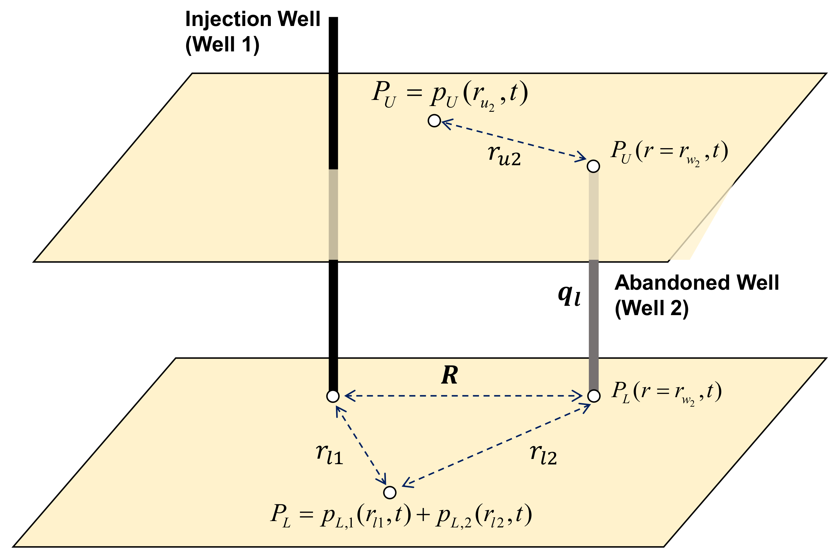
5. Solution with the Abandoned Well

We consider an abandoned well at a distance from the injection well (see Figure 2). The contribution of the abandoned well to the pressure in the lower layer can be incorporated by using the superposition in space. However, unlike the injection well, the leakage rate at the abandoned well is time-varying, where leakage can occur at an unknown time after the start of CO2 injection. The time-varying leakage rate can be expressed by the difference between the bottom hole pressure between the lower and upper layers and the flow resistance factor within the wellbore [34], that is,
q l ( t ) = ( P L ( r = r w 2 , t ) P U ( r = r w 2 , t ) ) / Ω
where ql[STB/D] is the leakage rate, rw2[ft] is the radius of the abandoned well, P L ( r = r w 2 , t ) [psi] is the bottom hole pressure for the abandoned well at the lower layer, P U ( r = r w 2 , t ) [psi] is the bottom hole pressure for the abandoned well at the upper layer, and Ω[psi/(STB/D)] is the flow resistance within the leaky well.
The leakage rate is unknown and time-varying, and therefore it is determined using a superposition-in-time approach, where the leakage rate is discretized into a piecewise constant function [47]. An example of the rate function discretization is shown in Figure 3.
Because of the rock and fluid compressibility, the fluid leakage at the abandoned well does not occur simultaneously with fluid injection (see Figure 3). As a result, the leakage rate stays zero until an increase in the bottom-hole pressure at the abandoned well becomes high enough to cause leakage to the overburden layer. We refer to the corresponding breakthrough time by tb. Using the superposition of time, we subdivide the leakage rate into a series of constant rates, qi. For instance, the induced leakage rate, q1, occurs during the time interval t1tb. The bottom-hole pressure change caused by leakage at this time interval becomes
p L , 2 ( r = r w 2 , t = t 1 ) = q 1 a L E i b L r w 2 2 t 1 t b
a L = B μ 4 π α 2 k L h L
b L = ϕ L μ C t , L 4 α 1 k L
where pL,2[psi] is pressure change at lower layer caused by the abandoned well (well 2) only, and aL[psi/(STB/D)] and bL[h/ft2] are constant parameters related to the reservoir and fluid properties of the lower layer.
The pressure change by the abandoned well at the first time interval can be expressed in this form with the leakage rate. While the leakage rate at the first time interval is unknown, it is determined by the pressure difference across the abandoned well in the lower and upper layers.

6. Total Pressure Change and Leakage Rate

The pressure change in the lower layer is influenced by the combined injection and leakage events. With the superposition-in-space principle, the contributions of the injection and leakage wells on pressure can be quantified separately. The expression of the pressure changes by the injector, pL,1, and the leakage well, pL,2, are determined from Equations (7) and (9), respectively.
The total pressure in the lower layer at the abandoned well is the sum of the initial pressure and pressure changes from both wells, that is,
P L ( t = t 1 ) = p L , 1 ( r l 1 = R , t = t 1 ) + p L , 2 ( r l 2 = r w 2 , t = t 1 ) + p L , i = a L q E i b L R 2 t 1 q 1 a L E i b L r w 2 2 t 1 t b + p L , i
where pL,i[psi] is the initial pressure in the lower layer.
The pressure change in the upper layer is caused by the leakage well, which can be considered as an injection well into the upper layer. Like the lower layer, the pressure in the upper layer then can be expressed as
P U ( t = t 1 ) = p U , 2 ( r u 2 = r w 2 , t = t 1 ) + p U , i = q 1 a U E i b U r w 2 2 t 1 t b + p U , i
where pU,i[psi] is the initial pressure in the upper layer.
The abandoned well constrain for leakage flow can be applied for computing the leakage rate, as follows:
q 1 = ( P L ( r l 2 = r w 2 , t = t 1 ) P U ( r u 2 = r w 2 , t = t 1 ) G ) / Ω = p L , 1 ( r l 1 = R , t = t 1 ) + p L , 2 ( r l 2 = r w 2 , t = t 1 ) p U , 2 ( r u 2 = r w 2 , t = t 1 ) + p L , i p U , i G
where G is the gravitational potential difference between the lower and upper layers. Before injection happens, the reservoir is considered at hydrostatic equilibrium. This implies that the difference of initial pressure between the two layers is equal to the gravitational potential difference, and therefore the constant term in Equation (14) cancels out. The leakage rate is, therefore, expressed by the pressure change by injection and leakage, as follows:
q 1 = a L q E i ( b L R 2 t 1 ) a L q 1 E i ( b L r w 2 2 t 1 t b ) a U q 1 E i ( b U r w 2 2 t 1 t b ) / Ω
The leakage rate at the first time interval, q1, is the only unknown in Equation (15). It can be rearranged as
q 1 = q a L E i b L R 2 t 1 Ω 1 + a L E i ( b L r w 2 2 t 1 t b ) + a U E i ( b U r w 2 2 t 1 t b )
Similarly, the solution can be applied for all the following time intervals. The only difference is that the pressure change due to the abandoned well is influenced by the superposition of the leakage rates from all previous time intervals. With the superposition-in-time principle, the general form at any given time interval can be written as
p L , 2 ( r w 2 , t n ) = a L ( q n q n 1 ) E i b L r w 2 2 t n t n 1 + a L ( q n 1 q n 2 ) E i b L r w 2 2 t n t n 2 + + a L ( q 2 q 1 ) E i b L r w 2 2 t n t 1 + a L q 1 E i b L r w 2 2 t n t b
p U , 2 ( r w 2 , t n ) = a U ( q n q n 1 ) E i b U r w 2 2 t n t n 1 + a L ( q n 1 q n 2 ) E i b U r w 2 2 t n t n 2 + + a U ( q 2 q 1 ) E i b U r w 2 2 t n t 1 + a U q 1 E i b U r w 2 2 t n t b
The semi-analytical solution can be readily computed with a simple code, where the leakage rate and pressure change can be solved iteratively in five steps:
1.
Define the time intervals in terms of the total time.
2.
Compute the pressure change caused by injection at the abandoned well location pL,1(rl1 = R) for all time intervals.
3.
For the time intervals, when pressure change pL,1(rl1 = R, t = ti) is zero, the leakage rates ql (t = ti) are also recorded as zero.
4.
From the time interval, when the pressure change pL,1 (rl1 = R, t = tb) is not zero, the rest of leakage rates can be solved based on the abandoned well constraint (Equation (8)).
5.
With the leakage rates profile, the total pressure change can be solved by substituting the known rate back into Equations (17) and (18).

7. Results

The semi-analytical solution can be implemented readily to compute the leakage rate and pressure change. In Section 7.1, we first examine the influence of discretization of the leakage rate function. In Section 7.2, verification with the numerical simulator is then performed. In Section 7.3, sensitivity analyses are finally conducted to determine the effects of the different physical parameters.

7.1. Sensitivity of Leakage Rate Discretization

Discretization is used to approximate the leakage rate function with a piecewise constant function. This step is needed to address the variability in the leakage rate. We study the sensitivity of the solution to the level of discretization. A fine discretization tends to provide a more accurate approximation of the continuous leakage rate at the expense of higher computational time. We assessed the sensitivity of different time-interval discretizations. The problem inputs for this study case are reported in Table 1.
Figure 4A–D shows the leakage rate and pressure changes versus time obtained by six time-discretizations with dt = 0.01, 0.1, and 0.2 h, and dt = 1, 10, and 20 h, respectively. It is observed that the solution convergence of the leakage rates and pressure change, as time increases, is not impacted by the size of the discretization step.

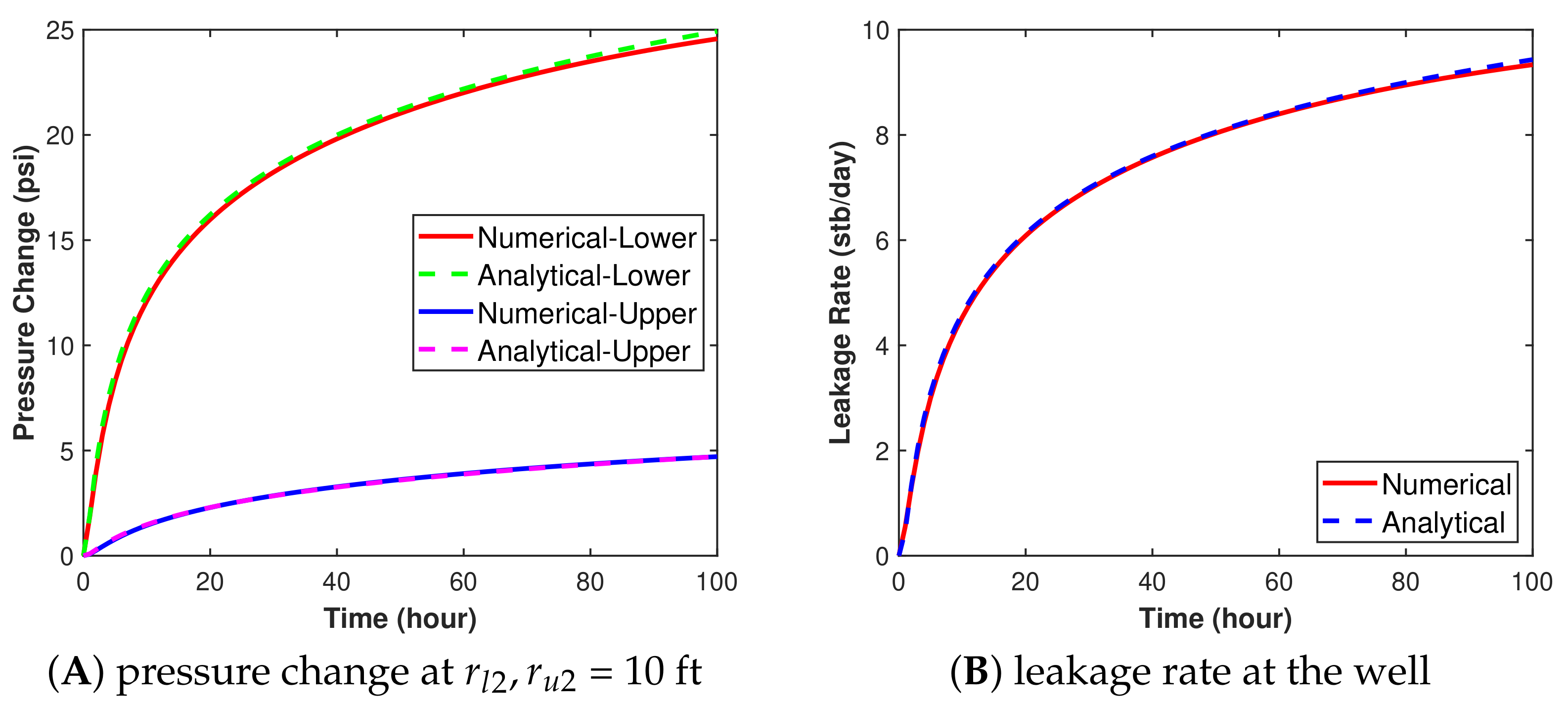
7.2. Solution Verification

To verify the proposed method, we compare the semi-analytical solutions with an industrial simulator by CMG. Several researchers have performed simulations with CMG to study CO2 flow problem [45,50]. We used the IMEX simulator in CMG for comparison. The details of the simulation grids are provided in Table 2. The pore volumes of the simulation grid blocks at the boundary of the simulation model were increased to one billion times that of the other blocks to mimic infinite boundary conditions. The abandoned well is located at the center of the reservoir, and the injection well is assigned to another block located at 60 ft radial distance from the abandoned well. The injected fluid is set the same as host fluid in the reservoir with the same physical properties, as discussed in the previous section (see Table 1).
Figure 5A shows the pressure changes versus time at two locations in the lower and upper layers, and Figure 5B shows the leakage rates versus time at the abandoned wells. The pressure results for both layers (Figure 5A) are obtained at 10 ft from the abandoned well. The results demonstrate excellent agreements between the semi-analytical and numerical solutions for the pressure profiles in upper layer and leakage rate profiles with Root Mean Square Error (RMSE) value of 0.0241 and 0.0507, respectively.
The pressure change at different times obtained by the semi-analytical and numerical methods versus the radial distance between the two wells also shows good agreement, as depicted in Figure 6. The injection well and abandoned well are located at D = 0 ft and D = 60 ft. We can observe from the results that the pressure increases gradually over distance in the first hour. When the bottom-hole pressure of the abandoned well starts to build up, the leakage flow will occur. However, the leakage rate is usually much lower than the injection rate, so it is difficult to see the influence of leakage on total pressure distribution at the beginning. After 10 h, pressure drawdown due to leakage becomes visible in the region near the abandoned well.
We also plot the pressure distribution maps by both methods at two different times, as shown in Figure 7, which shows good consistency in both distribution maps. This comparison indicates that the proposed solution can accurately capture the pressure change caused by leakage as well as the leakage rate.

7.3. Sensitivity Analysis

The semi-analytical solution was applied to check the effects of different uncertainty parameters on the pressure changes and leakage rate, where we conducted sensitivity analyses of different geological conditions. We studied the effect of the permeability in the lower layer, the distance between the two wells, and the flow resistance within the abandoned well. In each case, we keep the other parameters the same as provided in the example problem in Table 1 and vary the analyzed parameter to see its influence.
Figure 8 shows the leakage rate for three scenarios of the permeability in the lower layer, k = 10, 20, and 30 mD. The permeability in the upper layer is kept at 10 mD. The breakthrough time at the abandoned well decreases with the increased permeability (see Figure 8A). However, the cases with lower permeability showed higher leakage rates in the long term (see Figure 8B). This behavior is caused by higher local pressure build-up, resulting in a higher driving force for leakage. Figure 9A shows the leakage rate as a function of the flow resistance in the abandoned well. The fluid tends to leak at a higher rate as the flow resistance in the wellbore decreases, as expected. The resistance significantly changes the leakage rate behavior. The leakage rates decrease when the resistance increases (see Figure 9A). In Figure 9B, we show that as the distance between the abandoned well and injection well increases, the breakthrough time increases as well due to transient diffusivity of the pressure.
To better investigate the diffusivity, we show the radius of investigation, ri, which is a parameter reflecting the relationship between breakthrough time and the rock/fluid physical properties. It is a measure of the extent of the reservoir that has been influenced by the pressure disturbance [51], that is,
r i = 4 α 1 k t ϕ μ C t
where ri is the radius of investigation.
We can plot the radius as a function of time in different scales. The results are shown in Figure 10A,B in log-log and semi-log scales, respectively. The radius of investigation is linear in log-log scale. We can also plot the well distance versus breakthrough time to make a comparison in both scales. We choose threshold pressure as 1.5 psi for breakthrough time in the semi-analytical and numerical solution. The results show great agreement, which means the breakthrough time is close to the corresponding time when the radius of the investigation reaches the abandoned well location.

8. Conclusions

Leakage through abandoned wells is a concerning problem for CO2 storage in subsurface geological formations. This problem is challenging because of the lack of detailed subsurface data. Pressure transient analysis is a promising method that can be used to quantify the leakage process with limited information. In this work, we introduced a new semi-analytical solution to estimate the leakage rate and transient pressure behavior within the storage site and the overburden geological layer, hydraulically connected by an abandoned well. Fluid and rock compressibilities are taken into consideration, which overcame the restrictive assumption in the conventional solution. We subdivide the leakage rate into a piecewise constant function and applied a superposition-of-time principle. The proposed semi-analytical solution is easy to implement to assess the leakage rate and pressure change distribution. The solution was first examined to assess its convergence as a function of the time discretization. It showed that the ultimate solution in the long term is insensitive to the discretization level. Verification with numerical simulation was then conducted with an industrial simulator by CMG. The results showed excellent agreements between the semi-analytical and the numerical solutions. We demonstrate the potential of this semi-analytical solution to be applied efficiently for sensitivity analysis to understand the subsurface uncertainties in the context of CO2 storage leakage.

Author Contributions

T.Q. did the derivations, coding, visualizations, and initial drafting of the manuscript. H.H. conceptualized the work, defined the methodology, and verified the derivations and the writing. M.F. conceptualized the ideas, verified the analytical and numerical methods, and reviewed and edited the manuscript. All authors have read and agreed to the published version of the manuscript.

Funding

This research received no external funding.

Institutional Review Board Statement

Not applicable.

Informed Consent Statement

Not applicable.

Data Availability Statement

All data and codes used in this research are available upon request from the authors.

Acknowledgments

The authors thank Computer Modelling Group (CMG) Ltd. for providing the academic license of CMG simulators to the King Abdullah University of Science and Technology (KAUST).

Conflicts of Interest

The authors declare no conflict of interest.

Abbreviations

The following symbols are used in this manuscript:
aConstant parameters related to the reservoir and fluid properties
bConstant parameters related to the reservoir and fluid properties
BVolume formation factor
CRock/fluid compressibility
hLayer thickness
kPermeability
pFluid pressure
qFluid rate
rRadial distance
tTime
ϕPorosity
Ω Flow resistance within the leaky well
αUnit conversion constant
μFluid viscosity

References

  1. Dai, A. Drought under global warming: A review. Wiley Interdiscip. Rev. Clim. Chang. 2011, 2, 45–65. [Google Scholar] [CrossRef] [Green Version]
  2. Emanuel, K. Global warming effects on U.S. hurricane damage. Weather Clim. Soc. 2011, 3, 261–268. [Google Scholar] [CrossRef]
  3. Meehl, G.A.; Washington, W.M.; Collins, W.D.; Arblaster, J.M.; Hu, A.; Buja, L.E.; Strand, W.G.; Teng, H. How much more global warming and sea level rise? Science 2005, 307, 1769–1772. [Google Scholar] [CrossRef] [PubMed] [Green Version]
  4. Mousavi, M.E.; Irish, J.L.; Frey, A.E.; Olivera, F.; Edge, B.L. Global warming and hurricanes: The potential impact of hurricane intensification and sea level rise on coastal flooding. Clim. Chang. 2011, 104, 575–597. [Google Scholar] [CrossRef]
  5. Schiermeier, Q. Increased flood risk linked to global warming. Nature 2011, 470, 316. [Google Scholar] [CrossRef] [Green Version]
  6. Lashof, D.A.; Ahuja, D.R. Relative contributions of greenhouse gas emissions to global warming. Nature 1990, 344, 529–531. [Google Scholar] [CrossRef]
  7. Olivier, J.G.J.; Peters, J. Trends in Global CO2 and Total Greenhouse Gas Emissions: Report 2019; PBL Netherlands Environmental Assessment Agency: The Hague, The Netherlands, 2020; Volume 2020, p. 70. [Google Scholar]
  8. Bachu, S.; Bonijoly, D.; Bradshaw, J.; Burruss, R.; Holloway, S.; Christensen, N.P.; Mathiassen, O.M. CO2 storage capacity estimation: Methodology and gaps. Int. J. Greenh. Gas Control 2007, 1, 430–443. [Google Scholar] [CrossRef] [Green Version]
  9. IEA. CCUS in Clean Energy Transitions; IEA: Paris, France, 2020; Available online: https://www.iea.org/reports/ccus-in-clean-energy-transitions (accessed on 1 September 2020).
  10. Hoteit, H.; Fahs, M.; Soltanian, M.R. Assessment of CO2 injectivity during sequestration in depleted gas reservoirs. Geosciences 2019, 9, 199. [Google Scholar] [CrossRef] [Green Version]
  11. De Silva, P.N.K.; Ranjith, P.G. A study of methodologies for CO2 storage capacity estimation of saline aquifers. Fuel 2012, 93, 13–27. [Google Scholar] [CrossRef]
  12. Jia, B.; Tsau, J.S.; Barati, R. A review of the current progress of CO2 injection EOR and carbon storage in shale oil reservoirs. Fuel 2019, 236, 404–427. [Google Scholar] [CrossRef]
  13. Albattat, R.; Hoteit, H. A Semi-Analytical Approach to Model Drilling Fluid Leakage Into Fractured Formation. arXiv 2015, arXiv:2011.04746. [Google Scholar]
  14. Bachu, S.; Bennion, D.B. Experimental assessment of brine and/or CO2 leakage through well cements at reservoir conditions. Int. J. Greenh. Gas Control 2009, 3, 494–501. [Google Scholar] [CrossRef]
  15. Celia, M.A.; Bachu, S.; Nordbotten, J.M.; Gasda, S.E.; Dahle, H.K. Quantitative Estimation of CO2 Leakage from Geological Storage: Analytical Models, Numerical Models, and Data Needs; Elsevier Science Ltd.: Oxford, UK, 2005; pp. 663–671. [Google Scholar] [CrossRef]
  16. Koohbor, B.; Fahs, M.; Hoteit, H.; Doummar, J.; Younes, A.; Belfort, B. An advanced discrete fracture model for variably saturated flow in fractured porous media. Adv. Water Resour. 2020, 140. [Google Scholar] [CrossRef]
  17. Mehana, M.; Hosseini, S.A.; Meckel, T.A.; Viswanathan, H. Modeling CO2 plume migration using an invasion-percolation approach that includes dissolution. Greenh. Gases Sci. Technol. 2020, 10, 283–295. [Google Scholar] [CrossRef] [Green Version]
  18. Nicot, J.P.; Oldenburg, C.M.; Houseworth, J.E.; Choi, J.W. Analysis of potential leakage pathways at the Cranfield, MS, USA, CO2 sequestration site. Int. J. Greenh. Gas Control 2013, 18, 388–400. [Google Scholar] [CrossRef]
  19. Bielicki, J.M.; Pollak, M.F.; Deng, H.; Wilson, E.J.; Fitts, J.P.; Peters, C.A. The Leakage Risk Monetization Model for Geologic CO2 Storage. Environ. Sci. Technol. 2016, 50, 4923–4931. [Google Scholar] [CrossRef]
  20. Ran, X. Advanced Water Injection for Low Permeability Reservoirs: Theory and Practice; Gulf Professional Publishing: Oxford, UK, 2013. [Google Scholar]
  21. Syed, T.; Cutler, T. Well integrity technical and regulatory considerations for CO2 injection wells. In Proceedings of the SPE International Conference on Health, Safety and Environment in Oil and Gas Exploration and Production, Rio de Janeiro, Brazil, 12–14 April 2010; Volume 1, pp. 80–96. [Google Scholar] [CrossRef]
  22. Janiga, D.; Wojnarowski, P.; Stopa, J.; Czarnota, R. Technical conditions of well application for EOR-CCS project in Polish conditions. Int. Multidiscip. Sci. Geoconf. SGEM 2015, 1, 821. [Google Scholar]
  23. Dusseault, M.B.; Gray, M.N.; Nawrocki, P.A. Why Oilwells Leak: Cement Behavior and Long-Term Consequences. In Proceedings of the International Oil and Gas Conference and Exhibition in China, Beijing, China, 7–10 November 2000; pp. 623–630. [Google Scholar] [CrossRef]
  24. Gasda, S.E.; Bachu, S.; Celia, M.A. Spatial characterization of the location of potentially leaky wells penetrating a deep saline aquifer in a mature sedimentary basin. Environ. Geol. 2004, 46, 707–720. [Google Scholar] [CrossRef]
  25. Wisen, J.; Chesnaux, R.; Werring, J.; Wendling, G.; Baudron, P.; Barbecot, F. A portrait of wellbore leakage in northeastern British Columbia, Canada. Proc. Natl. Acad. Sci. USA 2020, 117, 913–922. [Google Scholar] [CrossRef]
  26. Guo, B.; Bandilla, K.W.; Doster, F.; Keilegavlen, E.; Celia, M.A. A vertically integrated model with vertical dynamics for CO2 storage. Water Resour. Res. 2014, 50, 6269–6284. [Google Scholar] [CrossRef]
  27. Busch, A.; Kampman, N. Migration and Leakage of CO2 From Deep Geological Storage Sites. In Geological Carbon Storage; American Geophysical Union (AGU): Washington, DC, USA, 2018; Chapter 14; pp. 283–303. [Google Scholar] [CrossRef]
  28. Humez, P.; Audigane, P.; Lions, J.; Chiaberge, C.; Bellenfant, G. Modeling of CO2 Leakage up Through an Abandoned Well from Deep Saline Aquifer to Shallow Fresh Groundwaters. Transp. Porous Media 2011, 90, 153–181. [Google Scholar] [CrossRef] [Green Version]
  29. Pawar, R.J.; Watson, T.L.; Gable, C.W. Numerical Simulation of CO2 Leakage through Abandoned Wells: Model for an Abandoned Site with Observed Gas Migration in Alberta, Canada. Energy Procedia 2009, 1, 3625–3632. [Google Scholar] [CrossRef] [Green Version]
  30. Hayek, M.; Mouche, E.; Mügler, C. Modeling vertical stratification of CO2 injected into a deep layered aquifer. Adv. Water Resour. 2009, 32, 450–462. [Google Scholar] [CrossRef]
  31. Hayek, M.; Younes, A.; Zouali, J.; Fajraoui, N.; Fahs, M. Analytical solution and Bayesian inference for interference pumping tests in fractal dual-porosity media. Comput. Geosci. 2018, 22, 413–421. [Google Scholar] [CrossRef]
  32. Shao, Q.; Fahs, M.; Hoteit, H.; Carrera, J.; Ackerer, P.; Younes, A. A 3-D Semianalytical Solution for Density-Driven Flow in Porous Media. Water Resour. Res. 2018, 54, 10094–10116. [Google Scholar] [CrossRef]
  33. Avci, C.B. Evaluation of flow leakage through abandoned wells and boreholes. Water Resour. Res. 1994, 30, 2565–2578. [Google Scholar] [CrossRef]
  34. Javandel, I.; Tsang, C.F.; Witherspoon, P.A.; Morganwalp, D. Hydrologic detection of abandoned wells near proposed injection wells for hazardous waste disposal. Water Resour. Res. 1988, 24, 261–270. [Google Scholar] [CrossRef] [Green Version]
  35. Nordbotten, J.M.; Celia, M.A.; Bachu, S. Analytical solutions for leakage rates through abandoned wells. Water Resour. Res. 2004, 40. [Google Scholar] [CrossRef]
  36. Nordbotten, J.M.; Celia, M.A.; Bachu, S.; Dahle, H.K. Semianalytical solution for CO2 leakage through an abandoned well. Environ. Sci. Technol. 2005, 39, 602–611. [Google Scholar] [CrossRef]
  37. Nordboiten, J.M.; Kavetski, D.; Celia, M.A.; Bachu, S. Model for CO2 leakage including multiple geological layers and multiple leaky wells. Environ. Sci. Technol. 2009, 43, 743–749. [Google Scholar] [CrossRef]
  38. Zeidouni, M.; Pooladi-Darvish, M. Leakage characterization through above-zone pressure monitoring: 2-Design considerations with application to CO2 storage in saline aquifers. J. Pet. Sci. Eng. 2012, 98–99, 69–82. [Google Scholar] [CrossRef]
  39. Zeidouni, M.; Vilarrasa, V. Identification of above-zone pressure perturbations caused by leakage from those induced by deformation. Environ. Earth Sci. 2016, 75. [Google Scholar] [CrossRef]
  40. Zeidouni, M.; Tran, N.H.; Munawar, M.D. Interpretation of above-zone pressure influence time to characterize CO2 leakage. Greenh. Gases Sci. Technol. 2017, 7, 1050–1064. [Google Scholar] [CrossRef]
  41. Ahmadi, M.A.; Chen, Z. Analytical Model for Leakage Detection in CO2 Sequestration in Deep Saline Aquifers: Application to ex Situ and in Situ CO2 Sequestration Processes. ACS Omega 2019, 4, 21381–21394. [Google Scholar] [CrossRef] [PubMed] [Green Version]
  42. Cihan, A.; Zhou, Q.; Birkholzer, J.T. Analytical solutions for pressure perturbation and fluid leakage through aquitards and wells in multilayered-aquifer systems. Water Resour. Res. 2011, 47, 1–17. [Google Scholar] [CrossRef]
  43. Cihan, A.; Birkholzer, J.T.; Zhou, Q. Pressure Buildup and Brine Migration During CO2 Storage in Multilayered Aquifers. GroundWater 2013, 51, 252–267. [Google Scholar] [CrossRef]
  44. Mu, L.; Liao, X.; Zhao, X.; Zhang, J.; Zou, J.; Chen, L.L.; Chu, H. Analytical model of leakage through an incomplete-sealed well. J. Nat. Gas Sci. Eng. 2020, 77, 103256. [Google Scholar] [CrossRef]
  45. Zeidouni, M. Analytical model of well leakage pressure perturbations in a closed aquifer system. Adv. Water Resour. 2014, 69, 13–22. [Google Scholar] [CrossRef]
  46. Oruganti, Y.D.; Bryant, S.L. Pressure build-up during CO2 storage in partially confined aquifers. Energy Procedia 2009, 1, 3315–3322. [Google Scholar] [CrossRef] [Green Version]
  47. Lee, J.; Rollins, J.B.; Spivey, J.P. Pressure Transient Testing; Henry, L., Ed.; Doherty Memorial Fund of AIME, Society of Petroleum Engineers: Richardson, TX, USA, 2003. [Google Scholar]
  48. Al-Kobaisi, M.; Ozkan, E.; Kazemi, H.; Ramirez, B. Pressure-Transient-Analysis of Horizontal Wells with Transverse, Finite-Conductivity Fractures. In Proceedings of the Canadian International Petroleum Conference, Calgary, AB, Canada, 13–15 June 2006. [Google Scholar] [CrossRef]
  49. Theis, C.V. The relation between the lowering of the piezometric surface and the rate and duration of discharge of a well using ground-water storage. EOS Trans. Am. Geophys. Union 1935, 16, 519–524. [Google Scholar] [CrossRef]
  50. Mao, Y.; Zeidouni, M.; Duncan, I. Temperature analysis for early detection and rate estimation of CO2 wellbore leakage. Int. J. Greenh. Gas Control 2017, 67, 20–30. [Google Scholar] [CrossRef]
  51. Stewart, G. Well Test Design & Analysis; PennWell Corporation: Tulsa, OK, USA, 2011. [Google Scholar]
Figure 1. Schematic of the CO2 storage site, where the leakage problem consisting of a CO2 injection well into the storage site and an abandoned well leaking with hydraulic conductivity to an upper geological layer.
Energies 14 02452 g001
Figure 2. Illustration of the lower and upper layers with the variables used in the solution method, where the abandoned well is located at distance R from the injection well.
Energies 14 02452 g002
Figure 3. Discretization of a leakage rate function into a piecewise constant function.
Energies 14 02452 g003
Figure 4. The leakage rate and pressure change solutions with different discretization intervals; dt = 0.01, 0.1, and 0.2 h (A,B), and dt = 1, 10, and 20 h (C,D) show that the ultimate solution is not impacted significantly by the discretization steps.
Energies 14 02452 g004
Figure 5. Comparison between the semi-analytical and the numerical solutions for the pressure change in the lower and upper layers (A) and the leakage rates (B).
Energies 14 02452 g005
Figure 6. Pressure change profile versus radial distance between the injector and the leakage wells in the lower layer.
Energies 14 02452 g006
Figure 7. Comparison of the pressure distribution maps obtained by the semi-analytical and numerical methods in the lower layer after 24 h (A,B) and 240 h (C,D).
Energies 14 02452 g007
Figure 8. Leakage rate profiles for three scenarios where the permeability in the lower layer corresponds to k = 10, 20, and 30 mD.
Energies 14 02452 g008
Figure 9. Comparison of leakage rate profiles with different flow resistances in the abandoned well (A) and different well spacing (B).
Energies 14 02452 g009
Figure 10. Radius of investigation versus time in semi-log and log-log scales.
Energies 14 02452 g010
Table 1. Reservoir and fluid properties of the problem.
Porosity for both layers (dimensionless)0.3
Rock compressibility (1/psi)9 × 10−6
Fluid compressibility (1/psi)3 × 10−6
Fluid density (lb/ft3)62
Permeabilities of both layers (mD)10
Viscosity (cp)1
Injection rate (STB/D)100
Well distance (ft)60
Wellbore radius of the abandoned well (ft)0.5
Resistance of abandoned well (psi/(STB/D))1
Layer thickness (ft) for both layers100
Table 2. Reservoir and grid properties in the numerical model.
Reservoir thickness (ft)300
Reservoir length (ft)10,100
Reservoir width (ft)10,100
Number of grid blocks in the x-direction101
Number of grid blocks in the y-direction101
Number of grid blocks in the z-direction10
Publisher’s Note: MDPI stays neutral with regard to jurisdictional claims in published maps and institutional affiliations.

