Article

Stability Enhancement of a Single-Stage Transonic Axial Compressor Using Inclined Oblique Slots

Department of Mechanical Engineering, Inha University, Incheon 22212, Korea
*
Author to whom correspondence should be addressed.
Energies 2021, 14(9), 2346; https://doi.org/10.3390/en14092346
Submission received: 26 March 2021 / Revised: 9 April 2021 / Accepted: 12 April 2021 / Published: 21 April 2021
(This article belongs to the Special Issue Advances in Gas Turbine Performance, Heat Transfer and Aerodynamics)

Abstract

:
A casing treatment using inclined oblique slots (INOS) is proposed to improve the stability of the single-stage transonic axial compressor, NASA Stage 37, during operation. The slots are installed on the casing of the rotor blades. The aerodynamic performance was estimated using three-dimensional steady Reynolds-Averaged Navier-Stokes analysis. The results showed that the slots effectively increased the stall margin of the compressor with slight reductions in the pressure ratio and adiabatic efficiency. Three geometric parameters were tested in a parametric study. A single-objective optimization to maximize the stall margin was carried out using a Genetic Algorithm coupled with a surrogate model created by a radial basis neural network. The optimized design increased the stall margin by 37.1% compared to that of the smooth casing with little impacts on the efficiency and pressure ratio.

1. Introduction

The aerodynamic performance and stability of a compressor are affected by various factors. For transonic compressors, tip leakage vortex is a notable source of instability and loss, which greatly limits the machine’s safety and performance. This mainly resulted from its interaction with the in-passage shock. Many studies showed that the topology of the tip leakage vortex changes considerably from design condition to near-stall/stall condition [1,2,3,4]. At the design condition, under a moderate pressure ratio, the vortex has a stable structure and can pass through the passage shock without difficulty. However, as the compressor becomes throttled toward the stall condition, the pressure ratio significantly increases, the shock moves forward, and the vortex experiences a severe deceleration across the passage shock barrier. This results in a vortex breakdown and formation of low momentum regions, which act as blockages to the main flow. As the compressor moves closer to the stall condition, the blockages expand until a limit is reached, and finally stall occurs, causing severe instability and degradation of aerodynamic performance.
One way to delay stall inception induced by the tip leakage vortex is the casing treatment using slots. Airflow is recirculated through the slots due to the pressure difference. The recirculating flows re-energize the low energy air in the blockage zone. More detailed descriptions of the axial slot’s enhancing mechanism and its interaction with the main flow can be found in the works of Wilke and Kau [5] and Schnell et al. [6]. Wilke et al. [7] examined the effects of semi-circular slots on the aerodynamic performance of the NASA Rotor Stage 37. Their best configuration, which comprised 4 slots per passage covering 50% of the blade’s chord, increased the mass flow range by 60% with a 0.7% improvement in the maximum pressure ratio. Lu et al. [8] carried out an experimental and numerical study on a casing treatment using six bent skewed slots per passage in a low-speed subsonic compressor. With an exposure of 33.3% of the rotor’s axial chord, the treatment provided an improvement of about 22% with a slight increase in isentropic efficiency. A numerical study by Goinis et al. [9] applied surrogate models with an evolutionary algorithm to search for an optimal axial-slot design for the first stage of a transonic axial compressor. The optimal configurations successfully increased the stall margin without a noticeable penalty in efficiency.
Streit et al. [10] attempted to alleviate the efficiency penalty when using axial-slot treatment in a 1.5-stage transonic axial compressor with rotor redesign. The numerical results indicated that incorporating the slot treatment allowed a lower number of rotor blades and about a 0.7% gain in efficiency with a sufficient stall margin improvement. Ma et al. [11] focused on alleviating the efficiency deficit generally caused by the application of an axial-slot casing treatment. From an extensive study with 21 designs for a low-speed large scale compressor and a transonic compressor, two slots geometries with isosceles-trapezoid shape were devised, which increased the peak efficiency by about 0.5%. An axial-slot design by Inzenhofer et al. [12] nearly doubled the compressor’s flow range with an improved pressure ratio. They concluded that the axial-slot enhanced the compressor’s stability by alleviating the pressure difference at the blade tip and ingesting a part of the low-momentum leakage air stream. Zhang et al. [13] examined the impacts of inverse blade angle slots on the efficiency and operating stability of the NASA Rotor 67. Three designs with different axial coverages and skewed angles were tested, and the highest stall margin improvement was 24.3% with a 0.755% loss in efficiency.
In the last couple of decades, surrogate-based optimization has shown great potential in the design of turbomachinery. The major advantages of this optimization technique are a significant reduction in time for the design and its ability to explore and discover unexpected designs. Samad and Kim [14] used the elitist non-dominated sorting genetic algorithm (NSGA-II) [15] and response surface approximation (RSA) [16] to optimize the blade shape of a transonic axial compressor. Two objective functions, total pressure ratio and adiabatic efficiency, were examined and with the two extreme-end designs of the Pareto front, they were increased by 1.76% and 0.41%, respectively. Kim et al. [17] conducted a shape optimization of an impeller in a centrifugal compressor, aiming to maximize the total pressure ratio. The pressure rise was successfully improved by 2.46% at the design condition using the Sequential Quadratic Programming (SQP) technique [18] coupled with a radial basis neural network (RBNN) [19]. Using the hybrid multi-objective evolutionary algorithm (MOEA) [20], Kim et al. [21] attempted to enhance the efficiency and mitigate the noise level of an axial fan. Khalfallah et al. [22] applied the NSGA-II algorithm and RBNN model to find an optimal design of a centrifugal compressor to maximize the efficiency and stall margin. Ma et al. [23] implemented the RBNN model with different optimization techniques to optimize a ring cavity for the stall margin improvement of a centrifugal compressor. Four algorithms, i.e., genetic algorithm (GA) [24], particle swarm optimization (PSO) [25], simulated annealing [26], and SQP, were tested and the PSO was most effective in terms of computing time and stall margin gain.
In the present study, a new slot casing treatment design for a transonic axial compressor is proposed, namely inclined oblique slots (INOS). Although there have been many investigations of the slot casing treatment, they mostly concern the use of axial designs with multiple slots per passage. The unique design of the INOS treatment, which makes an oblique angle with the compressor’s rotational axis, has not been investigated yet. In addition, the treatment comprises only one slot per passage, which may help facilitate the manufacturing process in real application. The focus of this study is on the treatment’s impact on the compressor’s operating stability and efficiency as well as pressure rise. Numerical analysis was used to analyze the compressor’s aerodynamic performance. A GA algorithm was implemented with RBNN modeling to maximize the stall margin improvement by INOS.

2. Compressor Model and Casing Treatment Design

The test subject in the present work is the single-stage transonic axial compressor, NASA Stage 37. The report from Reid and Moore [27] provided detailed information regarding the compressor’s geometry and aerodynamic performance. Other research has pointed out that this compressor exhibited a spike-type rotating stall that originated from the rotors’ tip ([4,7]), which makes it well-suited for the investigation of casing treatments. The compressor comprises 36 rotor blades rotating at a design speed of 17,185.7 rpm and 46 stationary stator blades. The tip clearances’ values are 0.0400 cm under the rotor shroud and 0.0762 cm over the stator hub, which correspond to 1.44% of axial chord length at the rotor tip and 2.11% of the axial chord length at the stator tip, respectively. From the experiment by Reid and Moore [27], when running at 100% design speed and peak efficiency condition, the compressor’s total pressure ratio and adiabatic efficiency were 2.00% and 84.00%, respectively, with a mass flow rate of 20.74 kg/s. At the near-stall condition, the compressor’s total pressure ratio was 2.093 and the mass flow rate was 19.60 kg/s. The mass flow rate reached 20.93 kg/s at the choking condition. The reference pressure and temperature were 101,325 Pa and 288.15 K, respectively.
The design and position of INOS are presented in Figure 1. The slots are positioned at the rotor tip casing. There are 36 slots in total and they are uniformly distributed with equal intervals around the compressor’s casing. Table 1 shows the geometric parameters of the casing treatment with their reference values: axial location (LF), slot’s width (W), slot’s depth (D), oblique angle (α), inclined angle (β), and slot’s circumferential coverage (γ). The coverage indicates the angle around the compressor axis. Except for the angles, the other parameters are non-dimensionalized using the axial chord length of the rotor blades at the tip (CR).

3. Numerical Analysis

3.1. Numerical Method

The aerodynamic analysis was conducted by solving the three-dimensional (3D) RANS equations with the commercial CFD code, ANSYS CFX 15.0® (ANSYS, Canonsburg, PA, USA) [28]. TurboGrid® and ICEM-CFD® were used to create a hexahedral mesh system for the computational domain. TurboGrid® was used to generate the mesh for the rotor and stator blocks (more information can be found in [29]). The slot’s mesh was created using ICEM-CFD® with the determinant quality kept at no less than 0.7. To save the computing time, only one compressor’s passage comprising one pair of rotor and stator was considered in the computation. As illustrated in Figure 2, the computational domain comprises three sub-domains: the rotor, stator, and slot. Assigning the boundary conditions, solving the governing equations, and post-processing the numerical results were performed by ANSYS CFX-Pre, CFX-Solver, and CFD-Post, respectively.
In order to obtain steady-state numerical solutions, a fully implicit element-based finite volume method was implemented to discretize the 3D governing differential equations. For the advection terms, a high-resolution scheme using the principles of Barth and Jesperson [30] was used. It has a second-order accuracy in space. Air as an ideal gas was selected as the working fluid. An average static pressure was set at the outlet of the stator domain to obtain steady-state results. At the inlet of the rotor domain, the turbulence intensity and total temperature were specified as 5% and 288.15 K, respectively.
Smooth and adiabatic conditions were applied to all wall boundaries. The side boundaries of the rotor and stator domains were specified with periodic conditions. To obtained steady-state results, these rotating and stationary blocks were linked by a general grid interface (GGI) method. As the GGI method, the frozen-rotor method was used at the interface between the rotor and stator domains (360°/36 = 10° for the rotor, 360°/46 = 7.826° for the stator) and also between the slot and rotor domains (4° for the slot and 10° for the rotor). The influences of the frozen-rotor method on the numerical results were compared with those of the stage method developed by Shim and Kim [31]. The k-ε turbulence model was used with a scalable wall function, while y+ values of the first nodes near the walls were maintained in a range of 20–100.
In this work, the numerical calculations were performed until the near-stall point, which shows the highest pressure ratio. Due to the intrinsic unsteady characteristics of the stall/surge phenomenon, strict criteria for the near-stall point must be implemented to achieve a reasonably accurate assessment with steady simulations. The convergence criteria used in this work were those suggested by Chen et al. [32]: The variation between the inlet and outlet mass flow rates is less than 0.3%, the inlet mass flow rate fluctuation is less than 0.001 kg/s for 300 steps, and the change of adiabatic efficiency is less than 0.3% per 100 steps.
To obtain the performance curve of the compressor, at the compressor’s outlet, the average static pressure was varied from the choking condition (0 Pa) to the near-stall condition with a step size of 100 Pa around the peak efficiency condition and a step size of 10 Pa (which corresponds to about 0.0001 kg/s of mass flow rate) at the near-stall condition. The convergence criterion for the root-mean-square residual of each governing equation was limited to 10−6. The calculations were carried out by a computer with an Intel i7-4930K 3.4 GHz CPU. Each operating point was obtained after 2–3 h’ simulation time, and it took about 70 h to find a performance curve on average.

3.2. Performance Parameters

Three parameters, i.e., the total pressure ratio (PR), adiabatic efficiency (η), and stall margin (SM), were used to assess the aerodynamic performance and operational stability of the transonic compressor with and without the casing treatment [29,33,34]:
P R = p t ,   o u t p t ,   i n
η = p t ,   o u t p t ,   i n γ 1 γ 1 T t ,   o u t T t ,   i n 1 × 100 %
S M = P R N S P R p e a k × m ˙ p e a k m ˙ N S 1 × 100 %
where p t , T t , and m ˙ are the total pressure, total temperature, and normalized mass flow rate, respectively. The subscripts in and out indicate the values which are measured at the compressor’s inlet and outlet, respectively. The subscripts peak and NS refer to the peak adiabatic efficiency and near-stall condition, respectively. The subscripts SC and CT refer to the smooth casing and casing treatment, respectively.

3.3. Grid Dependency Test

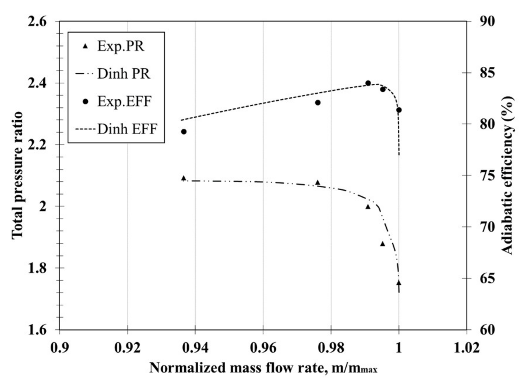
Detailed validation of the numerical results for the NASA Stage 37 compressor model without casing treatment can be found in the work of Dinh et al. [29]. The same numerical methods were used for the same compressor model in the present investigation. In Figure 3, the predicted performance curves show good agreements with the experimental data from Reid and Moore [27].
To evaluate the grid-dependency of the numerical results with the slots, the grid convergence index (GCI) based on Richardson extrapolation technique was analyzed in this work. This technique using GCI analysis was proposed by Celik and Karatekin [35] and is being widely accepted to find a grid-independent solution. In the computational domain except the casing slots, the grid system used in a previous work [29], was also used in the present work.
Table 2 presents detailed results of the GCI analysis of the mesh system in the slots. The result for the stall margin converges monotonically as the number of mesh elements increases. Since the deviation between the first (S1) and second (S2) mesh is insignificant, S2 was selected as the final number of elements for further calculation.

3.4. Optimization Technique

The single-objective optimization problem is defined as follows:
Maximize F x
x i L x i x i U
where F is an objective function and x (={xi}) is a vector of n design variables. An optimization algorithm performs a search procedure to find an optimal solution within the design space specified by the lower limit x i L and upper limit x i U of each design variable. The stall margin was selected as the objective function for optimization in the present study:
F = S M .
A design of experiment (DOE) was created using the Latin hypercube sampling (LHS) method [36]. Sampling points (or design points) are generated by LHS and are composed of an i × j matrix, where i and j represent the number of sampling points and design variables, respectively. Each column j is filled with a randomly paired permutation level of 1, 2, …, i to form a Latin hypercube. The method is provided as the function lhsdesign in MATLAB [18].
The objective function was built by surrogate modeling using RBNN. RBNN is a two-layer neural network that comprises a hidden layer of radial basis function and a linear output layer. The two hyperparameters of this surrogate model are an error goal and a spread constant. The former’s value can be chosen by the user based on the permissible error from the mean input response. MATLAB provides a built-in function, newrb, to apply RBNN modeling [18].
GA is a meta-heuristic population-based optimization technique, which replicates the process of natural selection, mutation, and evolution. Each solution is considered as a “chromosome”, which contains “genes” that are optimized values of design variables. The algorithm first starts with a random population of solution—the first generation. To imitate the “survival of the fittest” in nature, the fitness of each solution—the objective function, is evaluated to find the best chromosome. The offspring of these superior candidates are then created through crossover and mutation. If the new chromosomes have better fitness, they will evolve the population by replacing the ones with poorer fitness. This process is repeated through generations until terminate conditions are reached and optimal solutions are found. In MATLAB, the single-objective GA is included in the optimization toolbox and can be used by calling ga function [18]. The parameters of the algorithm were set as follow: population size (50), crossover fraction (0.8), generation (400), and function tolerance (10−4). The whole optimization process is presented in the flow chart in Figure 4.

4. Discussions

4.1. Results with the Reference INOS

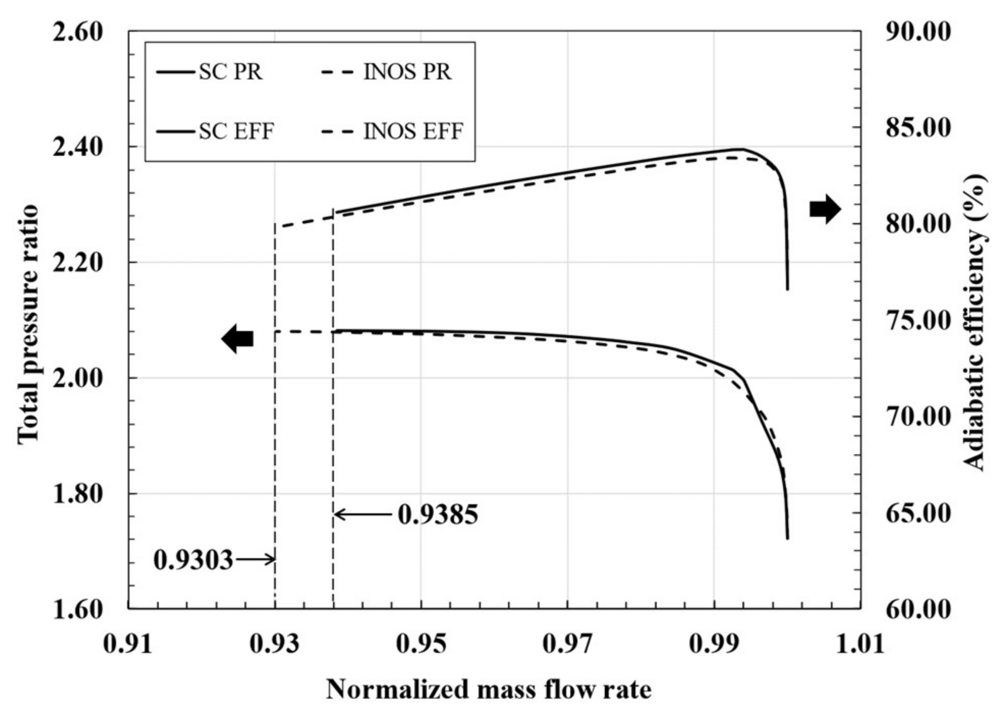
Figure 5 compares the performance curves between smooth casing and the reference INOS. In this figure, the mass flow rate is normalized by the maximum mass flow rate obtained at choke condition. As illustrated in the figure, the application of INOS extends the stable mass flow range of the compressor, by lowering the near-stall normalized mass flow rate from 0.9385 to 0.9303, with a small deficit of the pressure ratio. As a result, the stall margin of the compressor is increased from 9.95% of the smooth casing to 11.16% by installing the reference INOS. The peak adiabatic efficiency and maximal pressure ratio, however, are slightly reduced by 0.4% and 0.07%, respectively.
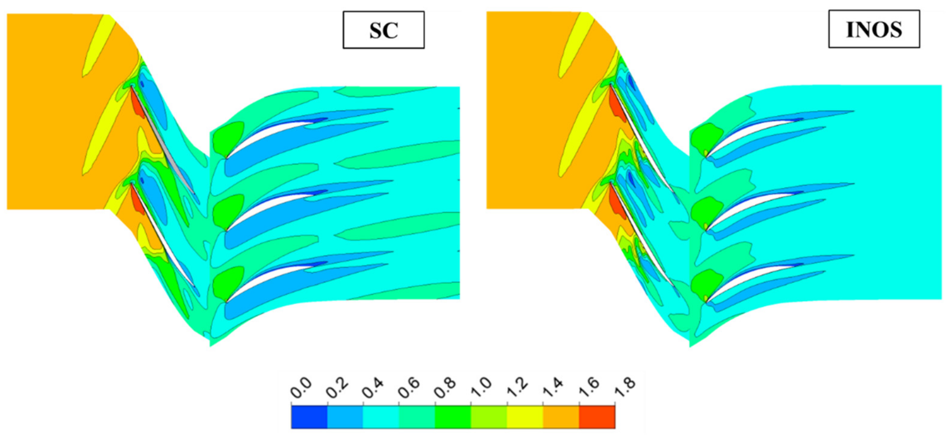
Since the impact of INOS is more pronounced at near-stall condition, the flow field at the low mass flow rate condition is analyzed comparatively, in Figure 6, which presents the relative Mach number contours of smooth casing and reference INOS at 98% blade span. The blockages in the passages are characterized by a Mach number lower than 0.4. It is evident that with the casing treatment applied, the size of these low-speed regions is significantly reduced compared to that of smooth casing, both in rotor and stator domains. In the rotor domain, the blockage area is shrunk from 4.39% of the rotor passage with smooth casing to 4.10% with INOS.
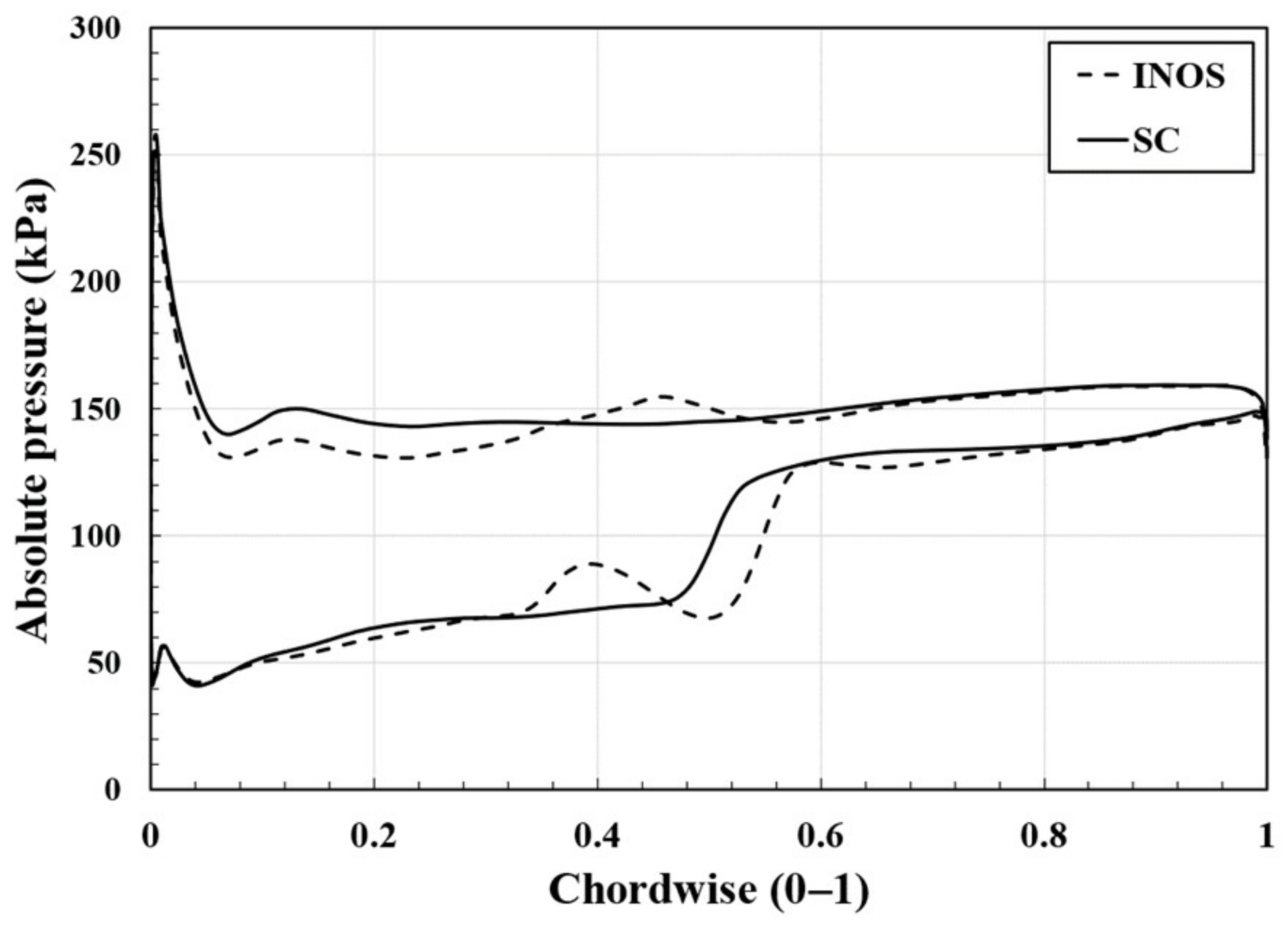
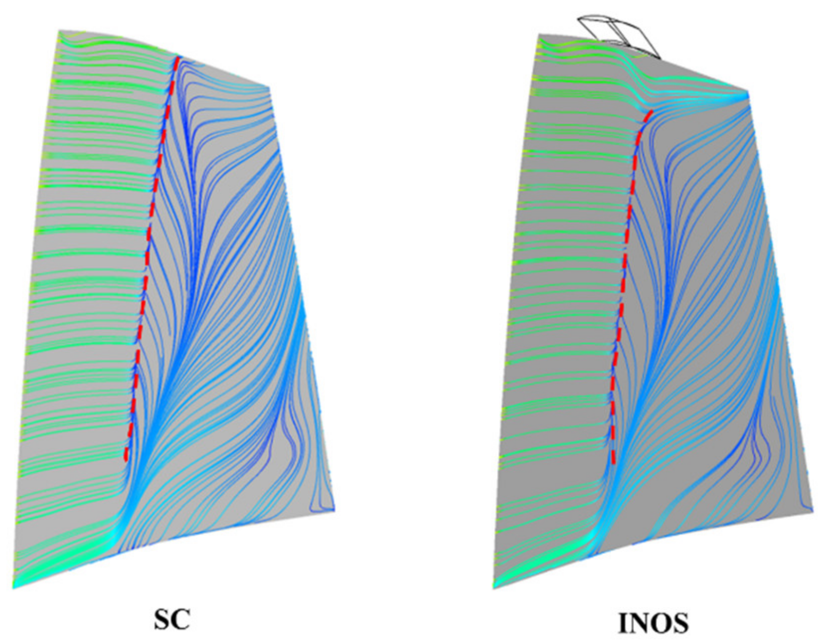
Furthermore, as illustrated in Figure 7, there is a notable decrease in the pressure difference between two sides of the rotor blade from the leading edge to the position of the slots at 40% blade chord. This helps to lower the amount of leakage flow fed to the vortex and impede the enlargement of the blockage zones. This reduction, however, may have caused the fall in pressure ratio at the near-stall condition. In addition, looking at the streamlines on the suction side of rotor in Figure 8, it is observed that the separation line (red dash line) is shorter with INOS. This change indicates that the casing treatment prevents flow separation from occurring at the tip region and from intensifying the instability. The overall improvement in stability is, therefore, speculated to be the combined result of all the changes above.
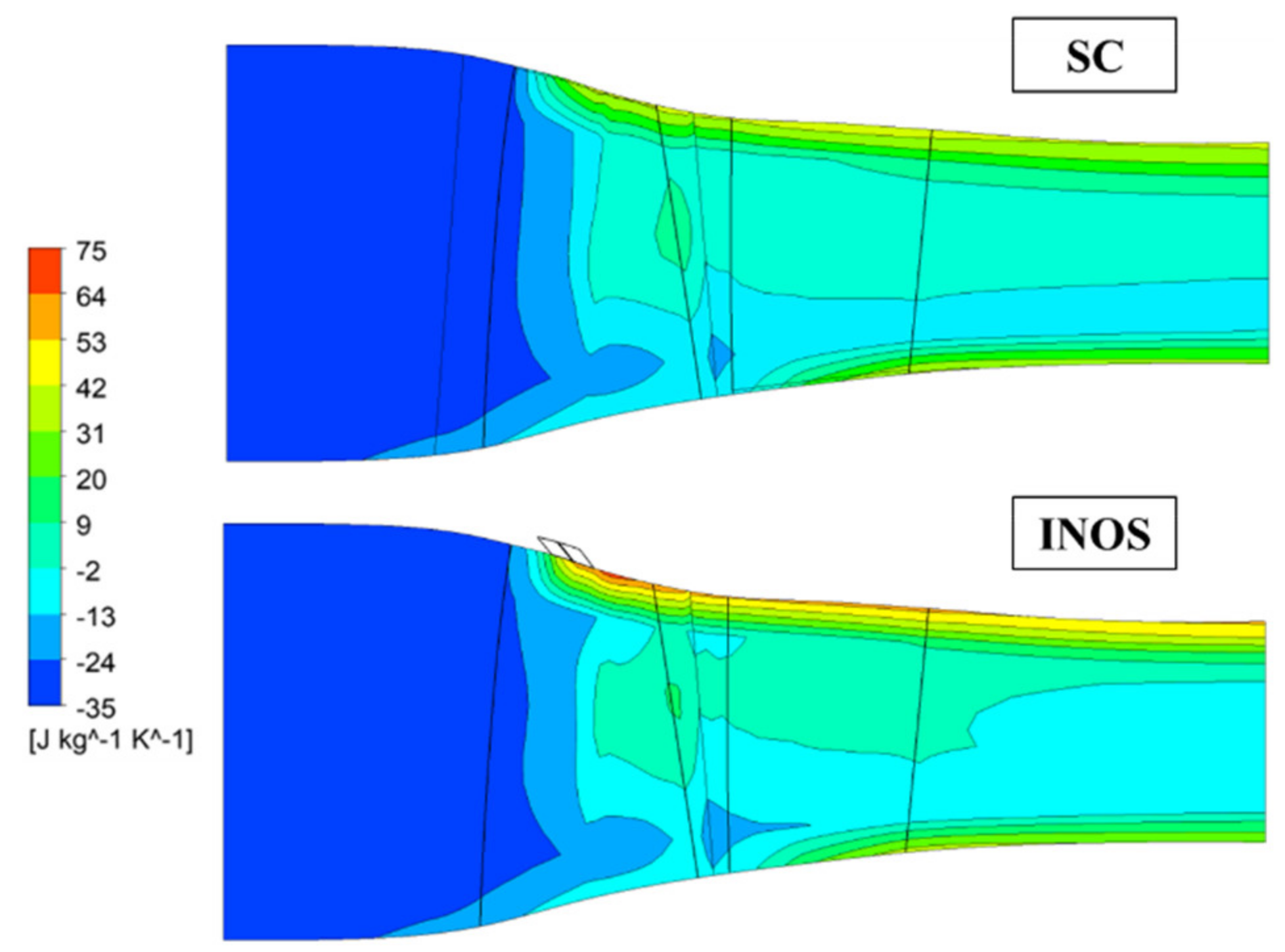
Figure 9 shows that when INOS is used, a region of high entropy, which is an indication of efficiency loss, is formed near the location of the slots. This loss can be attributed to the flow recirculation where the airflow spends energy moving in and out of the slots.

4.2. Parametric Study

The selection of design variables and their ranges to generate the DOE is of great importance in surrogate-based optimization. Narrowing the range for each variable will reduce the size of the DOE required to approximate an accurate surrogate model. It is also necessary to perform a sensitivity analysis, i.e., a parametric study, to find the parameters which are most influential on the objective function. Among the geometric parameters of INOS, the oblique angle (α), inclined angle (β), and the slot’s depth (D) were used for the parametric study. Their ranges are listed in Table 3.
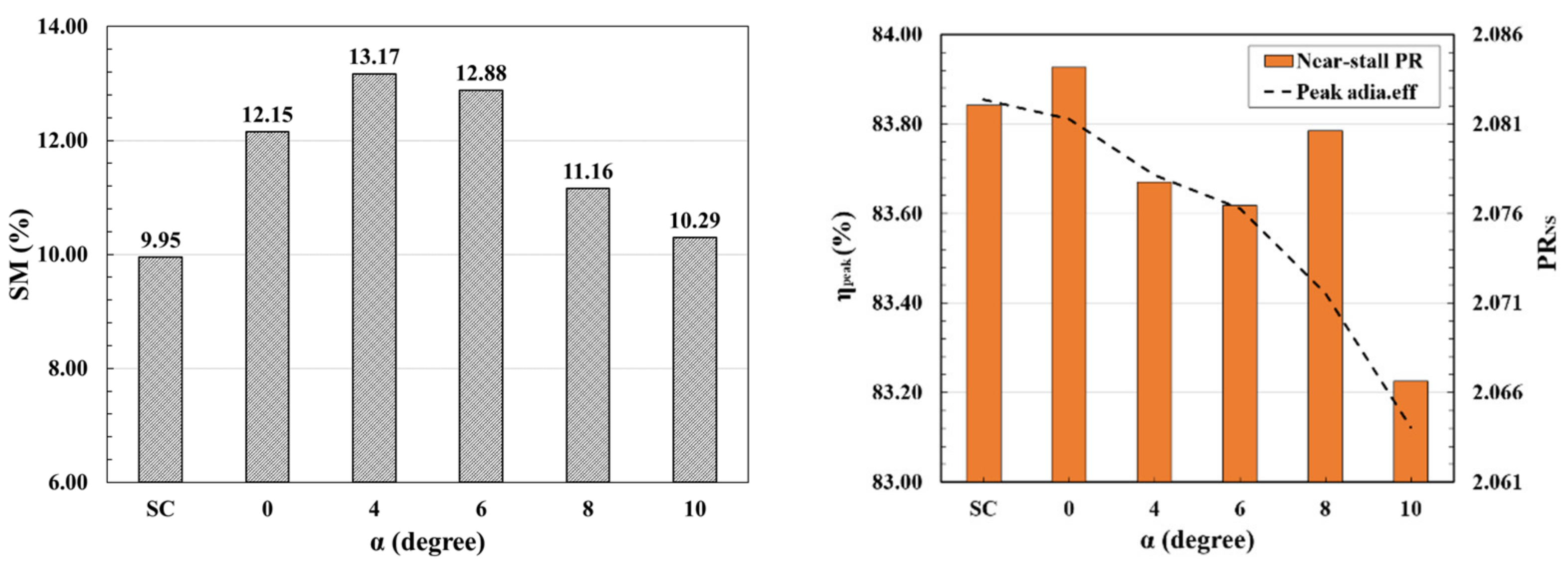
Figure 10 shows the effects of the oblique angle α on the stall margin, peak adiabatic efficiency (ηpeak), and near-stall total pressure ratio (PRNS). The stall margin reaches the maximum value of 13.17% at α = 4°. Meanwhile, increasing the oblique angle generally reduces peak adiabatic efficiency and near-stall total pressure ratio except at α = 8°. Notably, at α = 0°, the application of INOS increases the pressure ratio at near-stall condition with negligible reduction in efficiency compared to the case without casing treatment.
In Figure 11, it is found that the compressor achieves the highest stall margin of 13.59% when the inclined angle β is a right angle. Changing this angle has little impact on the peak adiabatic efficiency and near-stall total pressure ratio in a range of β from 60° to 90°.
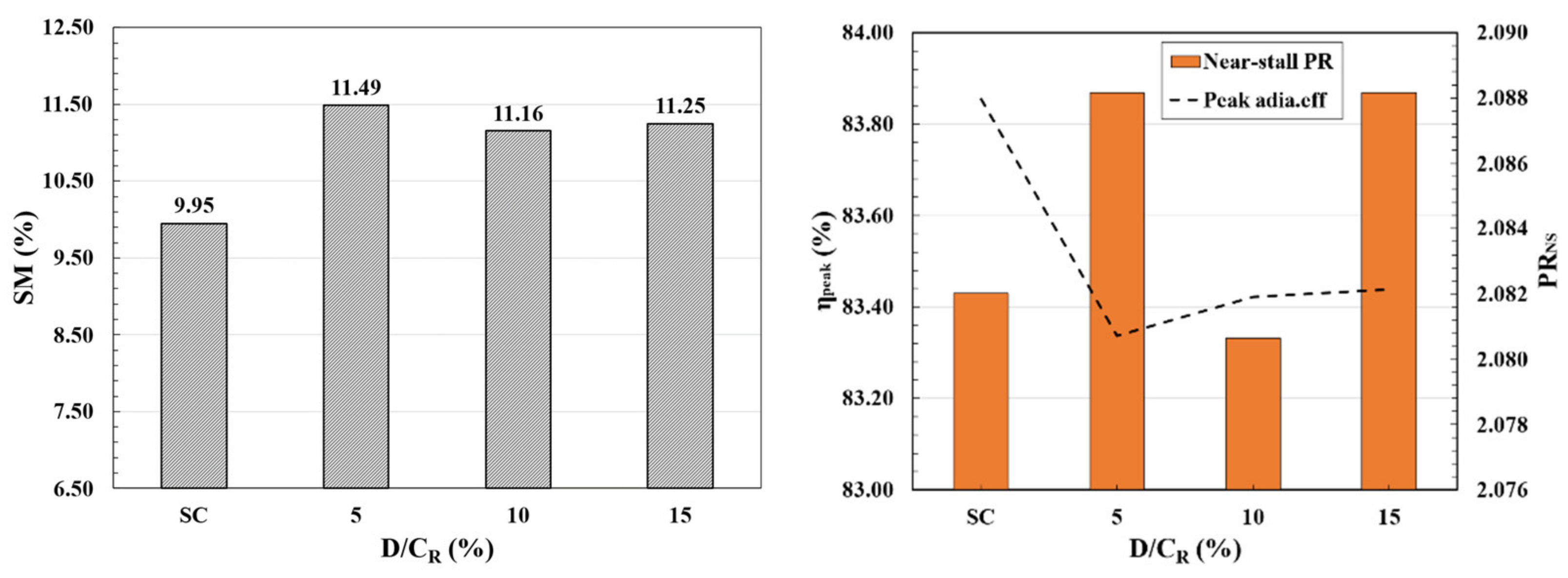
As illustrated in Figure 12, the influence of the slot’s depth on the stall margin and peak adiabatic efficiency is minimal. However, it has a discernible effect on the near-stall pressure ratio. D/CR = 10% shows the pressure ratio to be lower than that without casing treatment, but D/CR = 5% and 15% show 0.29% and 0.36% larger values, respectively.
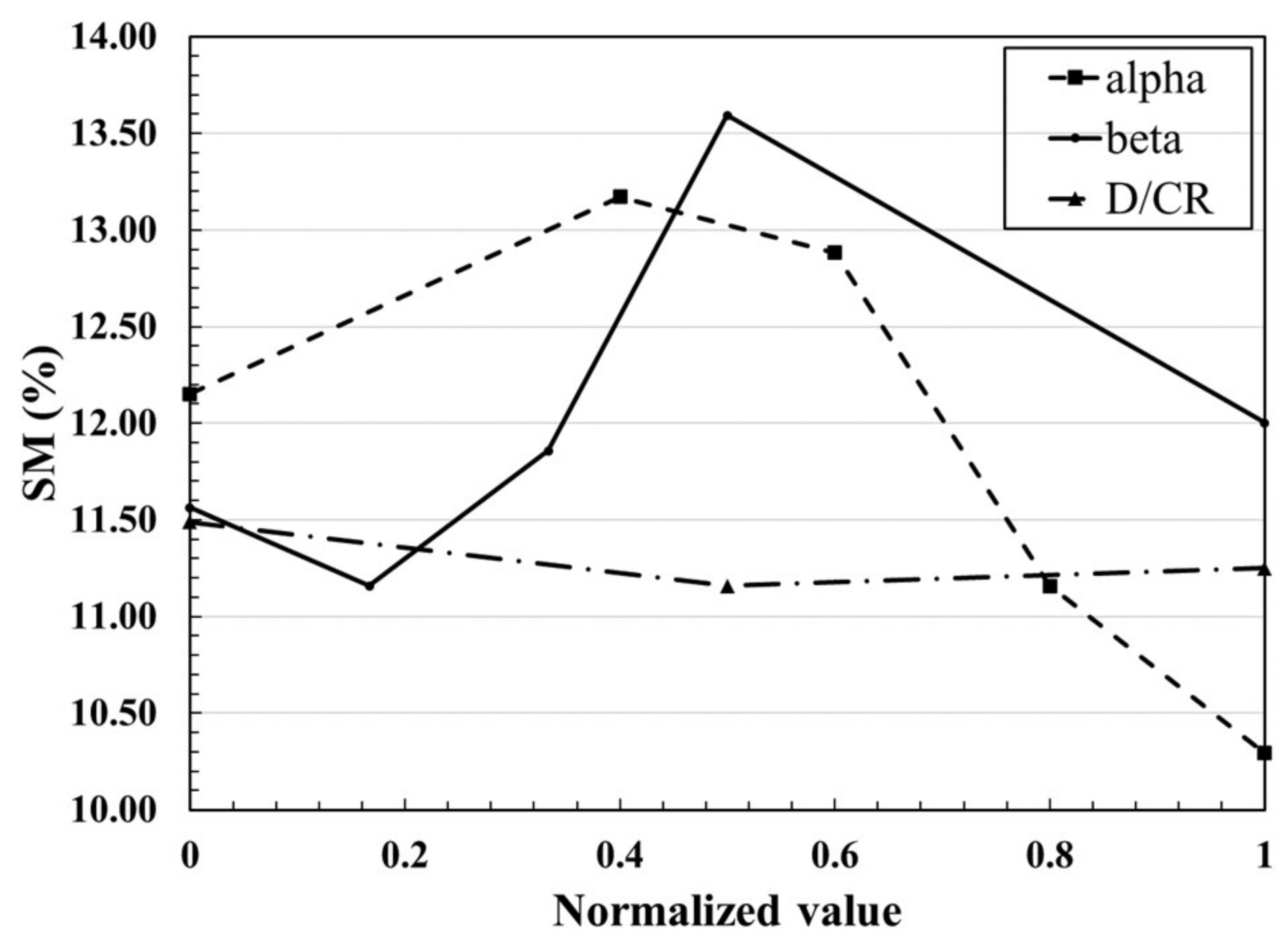
Based on the above results, sensitivities of the stall margin on the three parameters are compared in Figure 13. Since the sensitivity on the slot’s depth is negligible in comparison with the other parameters, the two angles, α and β, are chosen as design variables for the proceeding optimization.

4.3. Optimization

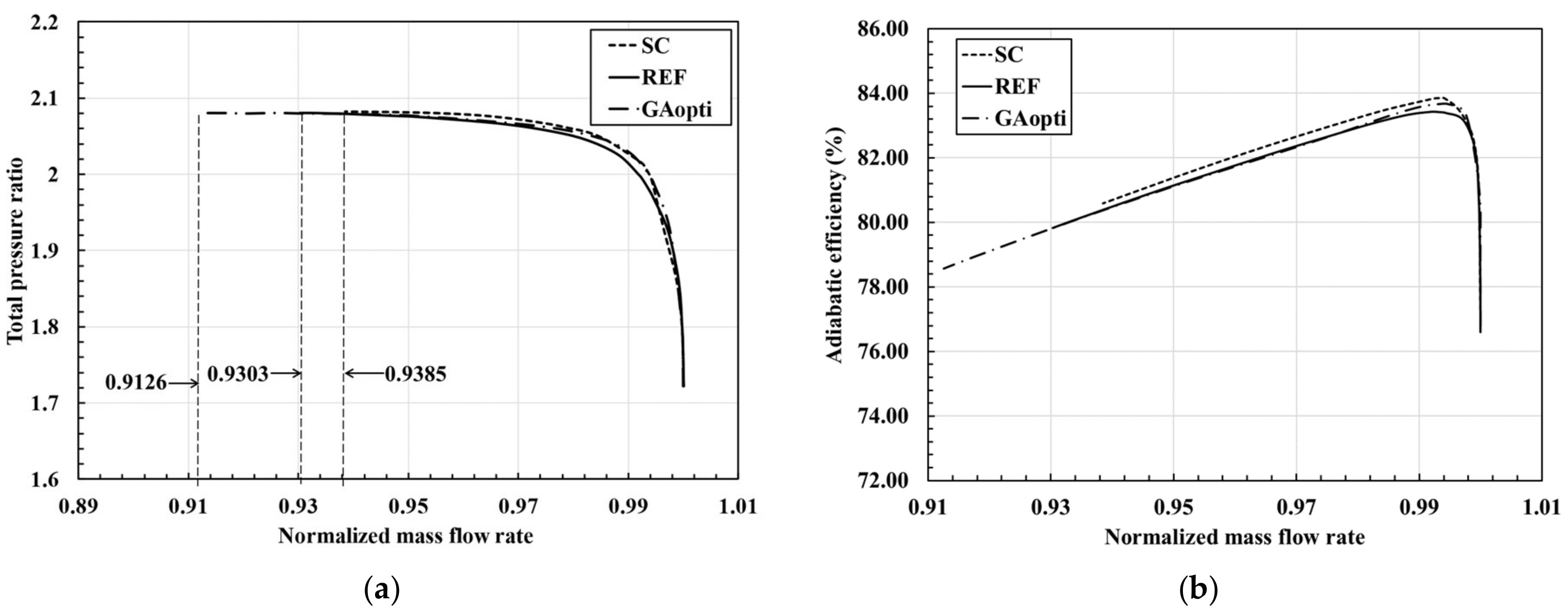
The LHS method was used to generate 12 design points and their stall margin values were obtained using RANS analysis. A RBNN surrogate model was constructed for the objective function, i.e., the stall margin, from these results and an optimal design, was found at α = 3.58° and β = 82.22° using GA. The results of the optimization are summarized in Table 4 and Table 5. The optimized stall margin was predicted to be 13.52%, but the result from RANS analysis at the optimal design was 13.64%, which are very close to each other. The optimization is clearly a success as the optimized INOS increased the stall margin to 13.64% from 11.16% of the reference design. In the following figures and tables, the smooth casing, reference design and optimized design are denoted by the subscripts, SC, REF, and GAopti, respectively.
Figure 14 shows that the optimized INOS extend the compressor’s operating flow range with little negative impact on pressure rise and efficiency. It also mitigates the efficiency loss compared to the reference design at the peak efficiency condition.
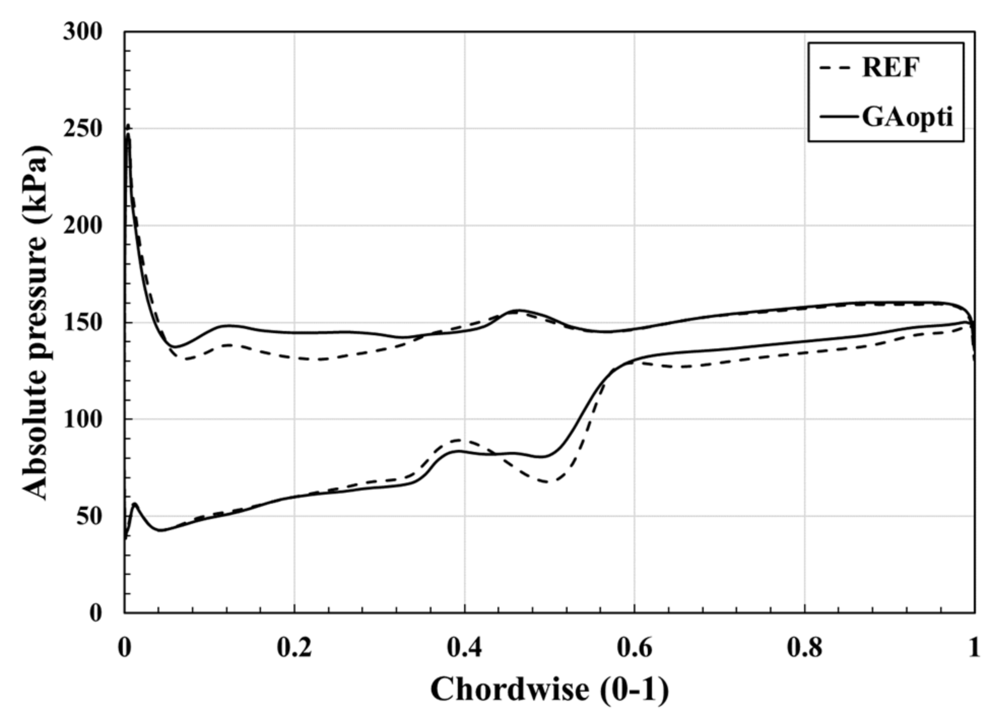
Figure 15 illustrates the relative Mach number contours at 98% blade span at near-stall condition for the reference and optimized designs of INOS. The optimized design shows the reduced blockage area in the rotor passage: it is only 3.58% of the total passage area compared to 4.10% with the smooth casing. A more favorable pressure distribution is also achieved with the optimal design. As shown in Figure 16, the pressure differences at the rotor’s leading edge and downstream of the slots are reduced compared to those of reference design.
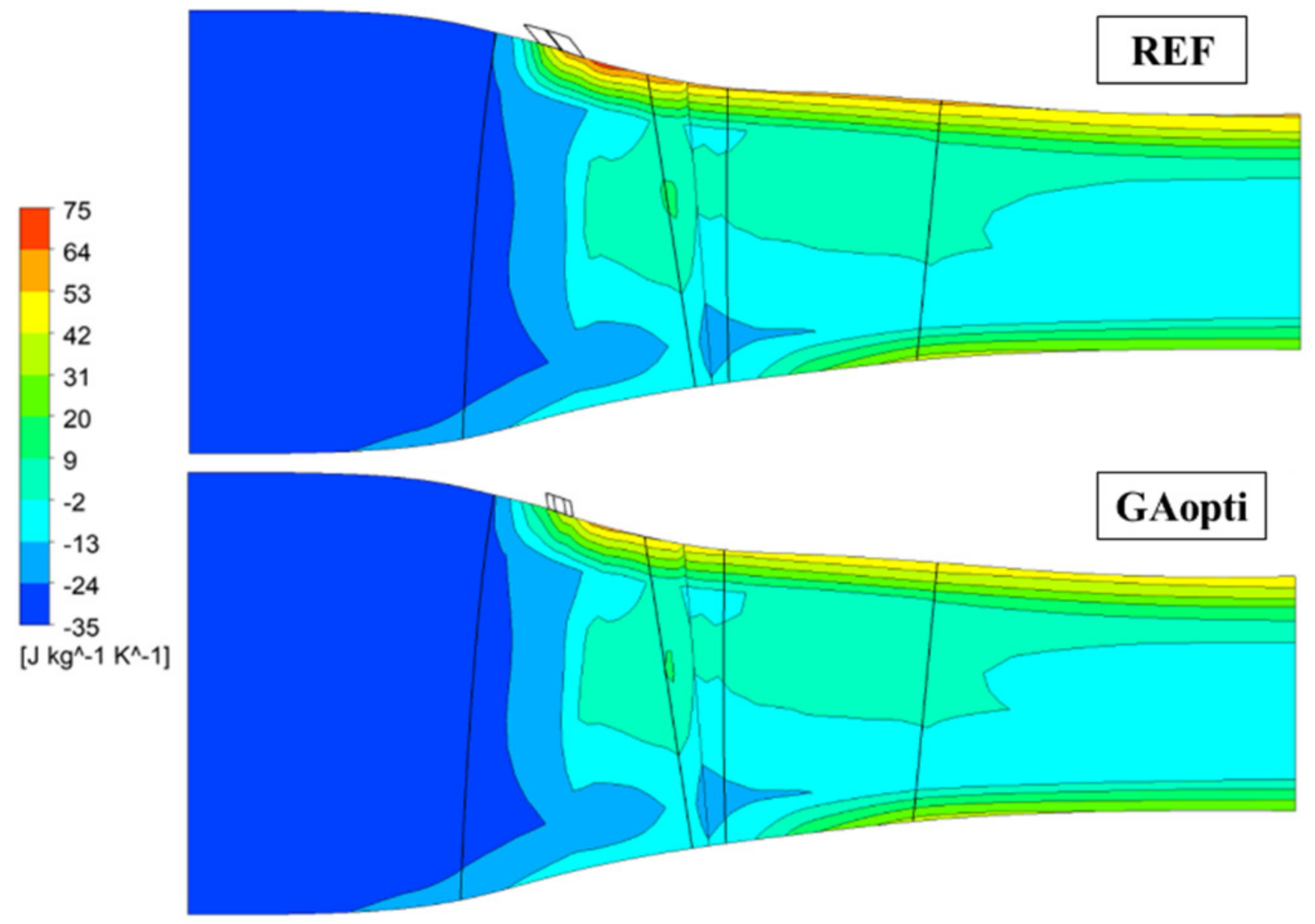
The improvement in the adiabatic efficiency with the optimized design can be explained by changes in entropy distribution shown in Figure 17. The high entropy area near the rotor’s tip, which is the indication of loss, is smaller in the case of the optimal design in comparison with that of the reference design.

5. Conclusions

INOS casing treatment was designed to enhance the operating stability of the single-stage transonic axial compressor, NASA Stage 37. Its impacts on the aerodynamic performance of the axial compressor were analyzed using 3D RANS analysis. The results confirmed the effectiveness of the proposed casing treatment on improving the stability of the compressor without significantly penalizing adiabatic efficiency and pressure ratio. The reference INOS increased the stall margin of the compressor to 11.16% from 9.95% without casing treatment. The oblique angle (α) and inclined angle (β) of INOS were selected as the design variables for the optimization through a sensitivity analysis. The optimal design found at α = 3.58° and β = 82.2° using GA coupled with RBNN model, achieved a stall margin of 13.64% which is improved by 37.1% with only 0.17% and 0.002% reductions in the peak adiabatic efficiency and maximum pressure ratio, respectively, compared with the case without casing treatment. By applying the single-objective optimization, it was possible to create an INOS design with a greater stability enhancement capability.
Nevertheless, to obtain in-depth information about the mechanism and advantages of the new treatment, a future work is needed to examine the unsteady behaviors at the near-stall condition, as well as the impact of the proposed casing treatment on the compressor’s mechanical integrity.

Author Contributions

T.-D.V. presented the main idea of the slot casing treatment for the axial transonic compressor, analyzed the proposed casing treatment, and performed numerical analysis. K.-Y.K. revised and finalized the manuscript. Both authors have read and agreed to the published version of the manuscript.

Funding

This work was supported by the National Research Foundation of Korea (NRF) grant funded by the Korean government (MSIT) (No. 2019R1A2C1007657).

Data Availability Statement

Not available.

Conflicts of Interest

The authors declare no conflict of interest.

References

  1. Inoue, M.; Kuroumaru, M. Structure of tip clearance flow in an isolated axial compressor rotor. J. Turbomach. 1989, 111, 250–256. [Google Scholar] [CrossRef]
  2. Adamczyk, J.J.; Celestina, M.L.; Greitzer, E.M. The role of tip clearance in high-speed fan stall. In Proceedings of the ASME Turbo Expo; ASME: New York, NY, USA, 1993; Volume 1. [Google Scholar] [CrossRef] [Green Version]
  3. Schlechtriem, S.; Lotzerich, M. Breakdown of tip leakage vortices in compressors at flow conditions close to stall. In Proceedings of the ASME Turbo Expo; ASME: New York, NY, USA, 1997; Volume 1, pp. 1–8. [Google Scholar] [CrossRef] [Green Version]
  4. Hofmann, W.; Ballmann, J. Tip clearance vortex development and shock-vortex-interaction in a transonic axial compressor rotor. In Proceedings of the 40th AIAA Aerospace Sciences Meeting and Exhibit, Reno, NV, USA, 14–17 February 2002. [Google Scholar] [CrossRef]
  5. Wilke, I.; Kau, H.P. A numerical investigation of the flow mechanisms in a high pressure compressor front stage with axial slots. J. Turbomach. 2004, 126, 339–349. [Google Scholar] [CrossRef]
  6. Schnell, R.; Voges, M.; Mönig, R.; Müller, M.W.; Zscherp, C. Investigation of blade tip interaction with casing treatment in a transonic compressor—Part II: Numerical results. J. Turbomach. 2011, 133, 2011. [Google Scholar] [CrossRef]
  7. Wilke, I.; Kau, H.P.; Brignole, G. Numerically aided design of a high-efficient casing treatment for a transonic compressor. Part A. In Proceedings of the ASME Turbo Expo; ASME: New York, NY, USA, 2005; Volume 6, pp. 353–364. [Google Scholar] [CrossRef]
  8. Lu, X.; Chu, W.; Zhang, Y.; Zhu, J. Experimental and numerical investigation of a subsonic compressor with bend-skewed slot-casing treatment. Proc. Inst. Mech. Eng. Part C J. Mech. Eng. Sci. 2006, 220, 1785–1796. [Google Scholar] [CrossRef]
  9. Goinis, G.; Voß, C.; Aulich, M. Automated optimization of an axial-slot type casing treatment for a transonic compressor. In Proceedings of the ASME Turbo Expo; ASME: New York, NY, USA, 2013; Volume 6B, pp. 1–13. [Google Scholar] [CrossRef]
  10. Streit, J.A.; Heinichen, F.; Kau, H.P. Axial-slot casing treatments improve the efficiency of axial flow compressors: Aerodynamic effects of a rotor redesign. In Proceedings of the ASME Turbo Expo; ASME: New York, NY, USA, 2013; Volume 6A. [Google Scholar] [CrossRef]
  11. Ma, N.; Nan, X.; Lin, F. Numerical study on effects of axial-slot casing treatment on peak efficiency of axial compressors. In Proceedings of the ASME Turbo Expo; ASME: New York, NY, USA, 2016; Volume 2A-2016, pp. 1–11. [Google Scholar] [CrossRef]
  12. Inzenhofer, A.; Guinet, C.; Hupfer, A.; Becker, B.; Grothe, P.; Heinichen, F. Difference in the working principle of axial slot and tip blowing casing treatments. In Proceedings of the ASME Turbo Expo; ASME: New York, NY, USA, 2016; Volume 2A-2016. [Google Scholar] [CrossRef]
  13. Zhang, H.; Liu, W.; Wang, E.; Chu, W.; Ding, K.; Yan, S. Effect of inverse blade angle slots on a transonic rotor performance and stability. Aerosp. Sci. Technol. 2020, 96, 105596. [Google Scholar] [CrossRef]
  14. Samad, A.; Kim, K.Y. Shape optimization of an axial compressor blade by multi-objective genetic algorithm. Proc. Inst. Mech. Eng. Part A J. Power Energy 2008, 222, 599–611. [Google Scholar] [CrossRef]
  15. Deb, K.; Pratap, A.; Agarwal, S.; Meyarivan, T. A fast and elitist multiobjective genetic algorithm: NSGA-II. IEEE Trans. Evol. Comput. 2002, 6, 2. [Google Scholar] [CrossRef] [Green Version]
  16. Lucas, J.M. Response surface methodology: Process and product optimization using designed experiments, 3rd edition. J. Qual. Technol. 2010, 42, 228–230. [Google Scholar] [CrossRef]
  17. Kim, J.-H.; Choi, J.-H.; Kim, K.-Y. Surrogate modeling for optimization of a centrifugal compressor impeller. Int. J. Fluid Mach. Syst. 2010, 3, 29–38. [Google Scholar] [CrossRef] [Green Version]
  18. MATLAB. The Language of Technical Computing-Release 14; Mathworks: Natick, MA, USA, 2004. [Google Scholar]
  19. Orr, M.J.L. Introduction to radial basis function networks. Network 1996. Available online: https://www.cc.gatech.edu/~isbell/tutorials/rbf-intro.pdf (accessed on 10 January 2021).
  20. Deb, K. Multi-Objective Optimisation Using Evolutionary Algorithms: An Introduction BT-Multi-Objective Evolutionary Optimisation for Product Design and Manufacturing; Wang, L., Ng, A.H.C., Deb, K., Eds.; Springer: London, UK, 2011; pp. 3–34. [Google Scholar]
  21. Kim, J.-H.; Ovgor, B.; Cha, K.H.; Kim, J.H.; Lee, S.; Kim, K.Y. Optimization of the aerodynamic and aeroacoustic performance of an axial-flow fan. AIAA J. 2014, 52, 2032–2044. [Google Scholar] [CrossRef]
  22. Khalfallah, S.; Ghenaiet, A.; Benini, E.; Bedon, G. Surrogate-based shape optimization of stall margin and efficiency of a centrifugal compressor. J. Propuls. Power 2015, 31, 1607–1620. [Google Scholar] [CrossRef]
  23. Ma, S.B.; Afzal, A.; Kim, K.Y. Optimization of ring cavity in a centrifugal compressor based on comparative analysis of optimization algorithms. Appl. Therm. Eng. 2018, 138, 633–647. [Google Scholar] [CrossRef]
  24. Goldberg, D.E. Genetic Algorithms in Search, Optimization and Machine Learning, 1st ed.; Addison-Wesley Longman Publishing Co., Inc.: Boston, MA, USA, 1989. [Google Scholar]
  25. Kennedy, J.; Eberhart, R. Particle swarm optimization. In Proceedings of the ICNN’95-International Conference on Neural Networks, Perth, WA, Australia, 27 November–1 December 1995; Volume 4, pp. 1942–1948. [Google Scholar] [CrossRef]
  26. Van Laarhoven, P.J.M.; Aarts, E.H.L. Simulated Annealing BT-Simulated Annealing: Theory and Applications; van Laarhoven, P.J.M., Aarts, E.H.L., Eds.; Springer: Dordrecht, The Netherlands, 1987; pp. 7–15. [Google Scholar]
  27. Reid, L.; Moore, R.D. Design and Overall Performance of Four Highly Loaded, High Speed Inlet Stages for an Advanced High-Pressure-Ratio Core Compressor; NASA Technical Paper 1337; NASA: Washington, DC, USA, 1978.
  28. ANSYS. ANSYS CFX-Solver Theory Guide Release 15.0; ANSYS: Canonsburg, PA, USA, 2014. [Google Scholar]
  29. Dinh, C.T.; Ma, S.B.; Kim, K.Y. Effects of a circumferential feed-back channel on aerodynamic performance of a single-stage transonic axial compressor. Proc. ASME Turbo Expo. 2017, 2A-2017, 57–65. [Google Scholar] [CrossRef]
  30. Barth, T.; Jespersen, D. The design and application of upwind schemes on unstructured meshes. In Proceedings of the 27th Aerospace Sciences Meeting, Reno, NV, USA, 9–12 January 1989; American Institute of Aeronautics and Astronautics: Washington, DC, USA, 1989. [Google Scholar]
  31. Shim, H.-S.; Kim, S.-H.; Kim, K.-Y. Analysis and optimization of staggered partial diffuser vanes in a centrifugal pump. J. Fluids Eng. 2020, 142. [Google Scholar] [CrossRef]
  32. Chen, H.; Huang, X.; Fu, S. CFD investigation on stall mechanisms and casing treatment of a transonic compressor. In Collection of Technical Papers-AIAA/ASME/SAE/ASEE 42nd Joint Propulsion Conference; ASME: New York, NY, USA, 2006; Volume 6, pp. 4789–4798. [Google Scholar] [CrossRef]
  33. Kim, J.H.; Choi, K.J.; Kim, K.Y. Performance evaluation of a transonic axial compressor with circumferential casing grooves. Proc. Inst. Mech. Eng. Part A J. Power Energy 2012, 226, 218–230. [Google Scholar] [CrossRef]
  34. Dinh, C.T.; Heo, M.W.; Kim, K.Y. Aerodynamic performance of transonic axial compressor with a casing groove combined with blade tip injection and ejection. Aerosp. Sci. Technol. 2015, 46, 176–187. [Google Scholar] [CrossRef]
  35. Celik, I.; Karatekin, O. Numerical experiments on application of richardson extrapolation with nonuniform grids. J. Fluids Eng. Trans. ASME 1997, 119, 584–590. [Google Scholar] [CrossRef]
  36. McKay, M.D.; Beckman, R.J.; Conover, W.J. A comparison of three methods for selecting values of input variables in the analysis of output from a computer code. Technometrics 1979, 21, 239–245. [Google Scholar] [CrossRef]
  37. Vuong, T.; Kim, K.; Dinh, C. Recirculation-groove coupled casing treatment for a transonic axial compressor. Aerosp. Sci. Technol. 2021, 111, 106556. [Google Scholar] [CrossRef]
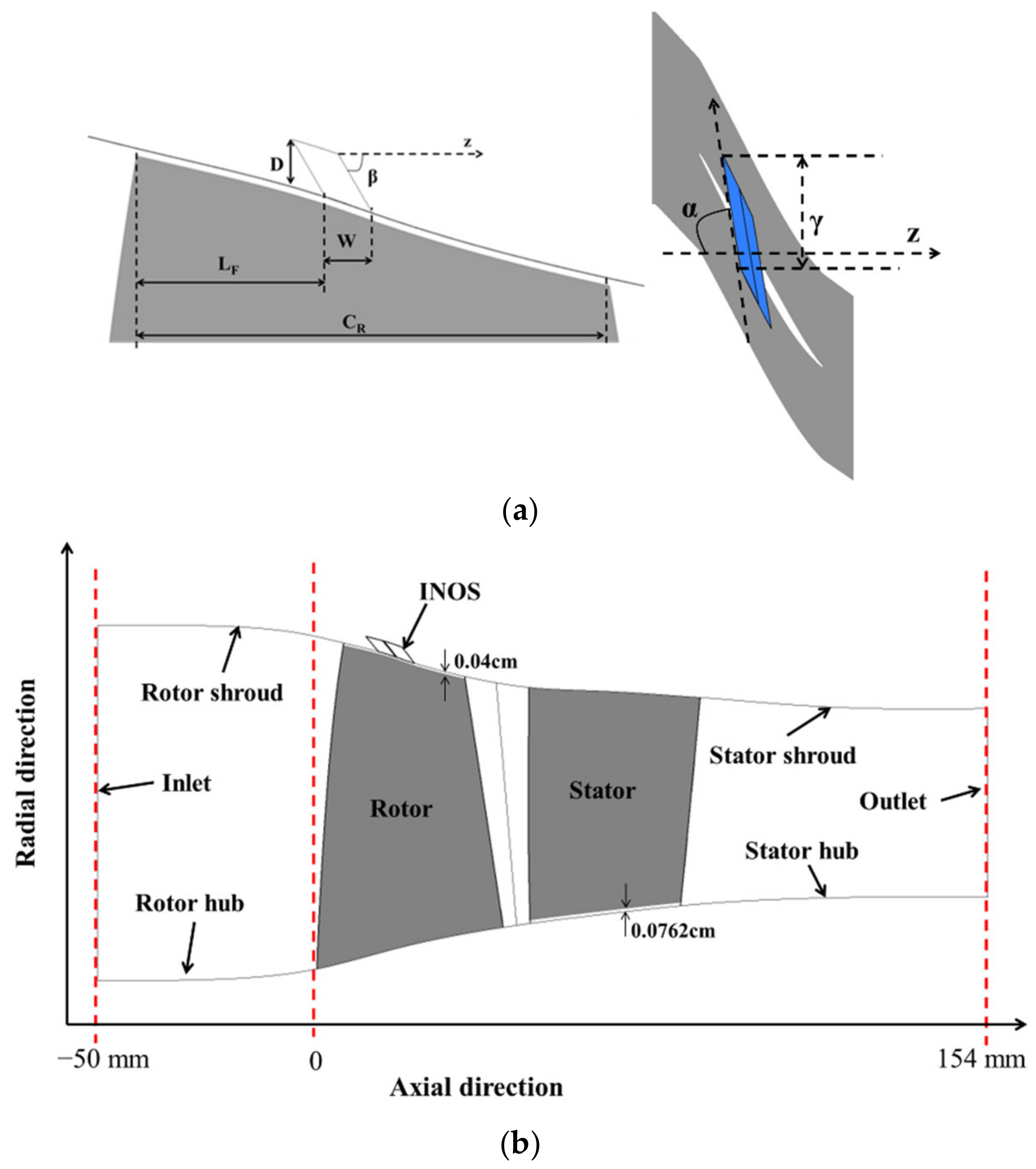
Figure 1. Description of the geometries of Stage 37 and INOS: (a) Geometric parameters of INOS; (b) Meridional view of Stage 37 with INOS.
Energies 14 02346 g001
Figure 2. Computational domain.
Energies 14 02346 g002
Figure 3. Validation of numerical results for NASA Stage 37 (Reprinted from ref. [29]. Copyright 2017 American Society of Mechanical Engineering).
Energies 14 02346 g003
Figure 4. Single-Objective optimization process.
Energies 14 02346 g004
Figure 5. Performance curves for smooth casing and reference INOS.
Energies 14 02346 g005
Figure 6. Relative Mach number contours at 98% blade span at near-stall condition (the left figure is reprinted from ref. [37]. Copyright 2021 Elsevier, Amsterdam, The Netherlands).
Energies 14 02346 g006
Figure 7. Rotor blade’s loading at 99% blade span at a near-stall condition.
Energies 14 02346 g007
Figure 8. Streamlines on rotor’s suction surface at the near-stall condition (the left figure is reprinted from ref. [37]. Copyright 2021 Elsevier).
Energies 14 02346 g008
Figure 9. Circumferentially-Averaged static entropy distribution at peak adiabatic efficiency condition.
Energies 14 02346 g009
Figure 10. Effects of oblique angle on aerodynamic performance.
Energies 14 02346 g010
Figure 11. Effects of inclined angle on aerodynamic performance.
Energies 14 02346 g011
Figure 12. Effects of slot’s depth on aerodynamic performance.
Energies 14 02346 g012
Figure 13. Sensitivity analysis of geometric parameters.
Energies 14 02346 g013
Figure 14. Performance curves of smooth casing, reference INOS and optimized INOS: (a) Total pressure ratio; (b) Adiabatic efficiency.
Energies 14 02346 g014
Figure 15. Relative Mach number contours at 98% blade span at the reference at near-stall condition.
Energies 14 02346 g015
Figure 16. Rotor blade’s loading at 99% span at near-stall condition.
Energies 14 02346 g016
Figure 17. Circumferentially averaged static entropy distribution at peak adiabatic efficiency condition.
Energies 14 02346 g017
Table 1. Reference values for INOS.
ParametersLF/CR (%)D/CR (%)W/CR (%)α (°)β (o)γ (°)
Values4010108604
Table 2. Analysis of grid convergence in slots.
ParametersSymbolsValues
Numbers of mesh elementsS1/S2/S387780/38353/17820
Grid refinement factorsr21/r321.3/1.3
Stall margins corresponding to S1/S2/S3SM1/SM2/SM311.15/11.16/11.18
Apparent orderp0.97
Extrapolated value ϕ e x t 21 11.14
Approximated relative error e a 21 0.0897%
Extrapolated relative error e e x t 21 0.0727%
Grid convergence index G C I f i n e 21 0.0908%
Table 3. Ranges of parameters tested in the parametric study.
ParametersLower BoundReference ValueUpper Bound
α (°)0810
β (°)4560135
D/CR (%)51015
Table 4. Comparison of objective function value between optimized design and other cases.
α (°)β (°)Objective Function (SM)Error (%)Improvement (%)
PredictionRANSvs. SCvs. REF
SC---9.95---
REF8.0060.00-11.16-12.14-
GAopti3.5882.2213.5213.640.8637.0522.19
Table 5. Changes in pressure ratio and adiabatic efficiency by optimization.
PRNSηpeakChange (%)
PRNSηpeak
SC2.0820383.85--
REF2.0806583.42−0.07−0.51
GAopti2.0802383.68−0.09−0.21
Publisher’s Note: MDPI stays neutral with regard to jurisdictional claims in published maps and institutional affiliations.