Article

Vibration Monitoring for Position Sensor Fault Diagnosis in Brushless DC Motor Drives

by
Dimitrios A. Papathanasopoulos
*,
Konstantinos N. Giannousakis
,
Evangelos S. Dermatas
and
Epaminondas D. Mitronikas
Department of Electrical and Computer Engineering, University of Patras, 26504 Patras, Greece
*
Author to whom correspondence should be addressed.
Energies 2021, 14(8), 2248; https://doi.org/10.3390/en14082248
Submission received: 15 March 2021 / Revised: 12 April 2021 / Accepted: 13 April 2021 / Published: 16 April 2021
(This article belongs to the Section F: Electrical Engineering)

Abstract

:
A non-invasive technique for condition monitoring of brushless DC motor drives is proposed in this study for Hall-effect position sensor fault diagnosis. Position sensor faults affect rotor position feedback, resulting in faulty transitions, which in turn cause current fluctuations and mechanical oscillations, derating system performance and threatening life expectancy. The main concept of the proposed technique is to detect the faults using vibration signals, acquired by low-cost piezoelectric sensors. With this aim, the frequency spectrum of the piezoelectric sensor output signal is analyzed both under the healthy and faulty operating conditions to highlight the fault signature. Therefore, the second harmonic component of the vibration signal spectrum is evaluated as a reliable signature for the detection of misalignment faults, while the fourth harmonic component is investigated for the position sensor breakdown fault, considering both single and double sensor faults. As the fault signature is localized at these harmonic components, the Goertzel algorithm is promoted as an efficient tool for the harmonic analysis in a narrow frequency band. Simulation results of the system operation, under healthy and faulty conditions, are presented along with the experimental results, verifying the proposed technique performance in detecting the position sensor faults in a non-invasive manner.

1. Introduction

Condition monitoring of electrical drive systems has been gaining attention in recent years as there is an increasing demand for proactive maintenance strategies. Research in this topic focuses on providing fast fault-detection methods to prevent catastrophic failures at a higher system level and minimize the financial losses under a possibly mandatory maintenance stop, caused by the fault. With this aim, Motor Current Signature Analysis (MCSA), speed, torque, noise, vibration signals, etc. are exploited under different condition-monitoring methods according to the investigated system and the specific fault [1].
Among them, the vibration signal analysis has long been proposed for condition-monitoring purposes on induction motors [2], offering an additional tool for an alternative non-invasive diagnostic approach. Thus, vibration monitoring has already been proposed for bearing, rotor, stator, and gear or axis fault diagnosis, mostly for induction motors and wind turbines [3,4,5,6,7,8,9,10]. Additional applications of piezoelectric sensors are recently reported in [11,12] for load estimation and undervoltage detection also in induction motor drives. Relative research has also been conducted for fault diagnosis of other electrical motor types, such as permanent magnet DC motors [13], while stator fault monitoring of brushless DC (BLDC) motors is presented in [14,15].
Brushless DC (BLDC) motor drives are preferred for applications, where the power density, efficiency, high starting torque, and noiseless operation are critical parameters for the system selection [16]. Thus, BLDC motors can be detected in industrial applications [17], electric vehicles [16], and aviation industry [18]. These drives can be classified into two main categories regarding the rotor position feedback and, consequently, sensored and sensorless setups can be distinguished. As the position sensors provide accurate information about the rotor angle, from zero to high speeds, they are mainly preferred in industrial applications compared to the sensorless drives [17]. With this aim, Hall-effect position sensors are usually selected for rotor position and speed feedback, as they combine a low cost and small volume with an acceptable resolution. Moreover, these sensors can be mounted either inside the stator slots or on a printed circuit board at the motor back, sensing a rotor magnet mirroring source.
A typical fault type, which is occurred in BLDC motors, is the well-known misalignment defect, caused by inaccurate positioning of the Hall-effect position sensors, resulting in unequal time intervals for the active phases. Thus, the sensor misalignment is a manufacturing defect, which affects the torque ripple due to asymmetrical current waveforms. On the other hand, a sensor breakdown fault may be caused by extreme operating conditions, such as increased temperature and vibrations, or broken wiring between the controller and the sensor. Either shorted or open circuited, in this case the sensor output signal retains its state, regardless of the rotor position, affecting both position and speed feedback.
Although the investigation of Hall-effect position sensor faults is a relatively new research topic, various methods for fault diagnosis and remedial strategies have been proposed both for the misalignment defect and the breakdown fault. Focusing on the latter fault type, single sensor fault diagnosis based on line-to-line voltages, Discrete Fourier Transform, and spectral energy density is proposed in [19]. Moreover, DC-link current and wavelet signal theory were used in [20], while motor phase current analysis with the Stockwell Transform is presented in [21]. However, the increased implementation cost due to the additional voltage and current sensors, especially for the cases of isolated power and control grounds, limit the applicability of these methods. Fault diagnosis based only on the position sensor signals is another option, as the sequence of the position sensor output signals is distorted under the sensor fault. Thus, fault detection by an unacceptable input with three sensors at the same high or low state is presented in [22,23], while the comparison of a direction-based predefined sensor sequence, stored in a lookup table, is proposed in [24,25]. In addition, a similar approach is considered in [26,27] for single and double sensor faults investigation in the α-β stationary reference frame, while diagnosis of multiple faults, based on the sensor state sequence, is also investigated in [28,29,30] under different procedures for rotor speed and position estimation. Recently, an approach based on binary functions is reported in [31] and a binary circuit is developed for the detection and identification of position sensor failures according to the various scenarios for different sensor failure under each different sector in the electrical cycle. Furthermore, a direct redundancy approach has been proposed in [32], using six Hall-effect position sensors. As previously mentioned, there are only a few studies using vibration analysis for fault detection in BLDC motor drives and only in [33] vibration signals are used for position sensor misalignment fault diagnosis under a multi-sensor scheme.
In this study, a novel approach for a non-invasive technique, based on vibration analysis for condition monitoring of brushless DC motor drives, is presented. BLDC motor drives are prone to position sensor misalignment and breakdown faults, which consequently cause torque and speed oscillations, affecting the drive system performance. If no action is taken, these oscillations may result in increased motor currents, threatening both the controller circuitry and the motor windings. As this fault situation threatens the system integrity, it cannot be tolerated when high reliability is required, such as in aerospace applications. Targeting towards these applications, a new diagnostic procedure, capable of detecting these oscillations through vibration monitoring, is proposed. As increased vibrations are expected under position sensor faults, piezoelectric sensors offer an inexpensive and non-invasive implementation compared to other published techniques. More precisely, the proposed method can be implemented as an external diagnostic tool, capable of detecting all the potential Hall-effect position sensor fault types, i.e., misalignment and single or double breakdown fault, without the need for hardware modification of the motor controller or additional external voltage or current sensors. In this way, a more generalized approach, independent of the drive system voltage and current ratings, can be achieved, as there is no need for doubling the required, application-based, current and voltage sensors. In addition, the proposed method is also independent of the Hall-effect position sensor signals. This feature minimizes the sensitive wiring of the sensors, eliminates the need for position sensor mapping according to the motor phases, and abolishes the requirement of doubling the position sensors or adding logic circuits for diagnostic purposes. Developing a smart sensor to acquire the required data and analyze the frequency spectra of the piezoelectric sensor signals, the system health state can be either locally or remotely monitored. Thus, the second harmonic component of the vibration frequency spectra is evaluated in this study for misalignment fault detection, while the fourth harmonic component is used to distinguish a position sensor breakdown fault from the misalignment fault. As the fault signature is localized at specific harmonic components of the system fundamental frequency, the Goertzel algorithm is proposed to limit the harmonic analysis in a narrow band, saving computational cost and memory demands, which is especially useful in the case of onsite implementation of the harmonic analysis. Moreover, system simulation has been implemented to demonstrate the impact of the position sensor faults to the motor currents and the electromagnetic torque. Finally, the experimental investigation of the system operation under the healthy and faulty conditions highlights the advantages of the piezoelectric transducers in detecting the faulty system operation.

2. System Overview

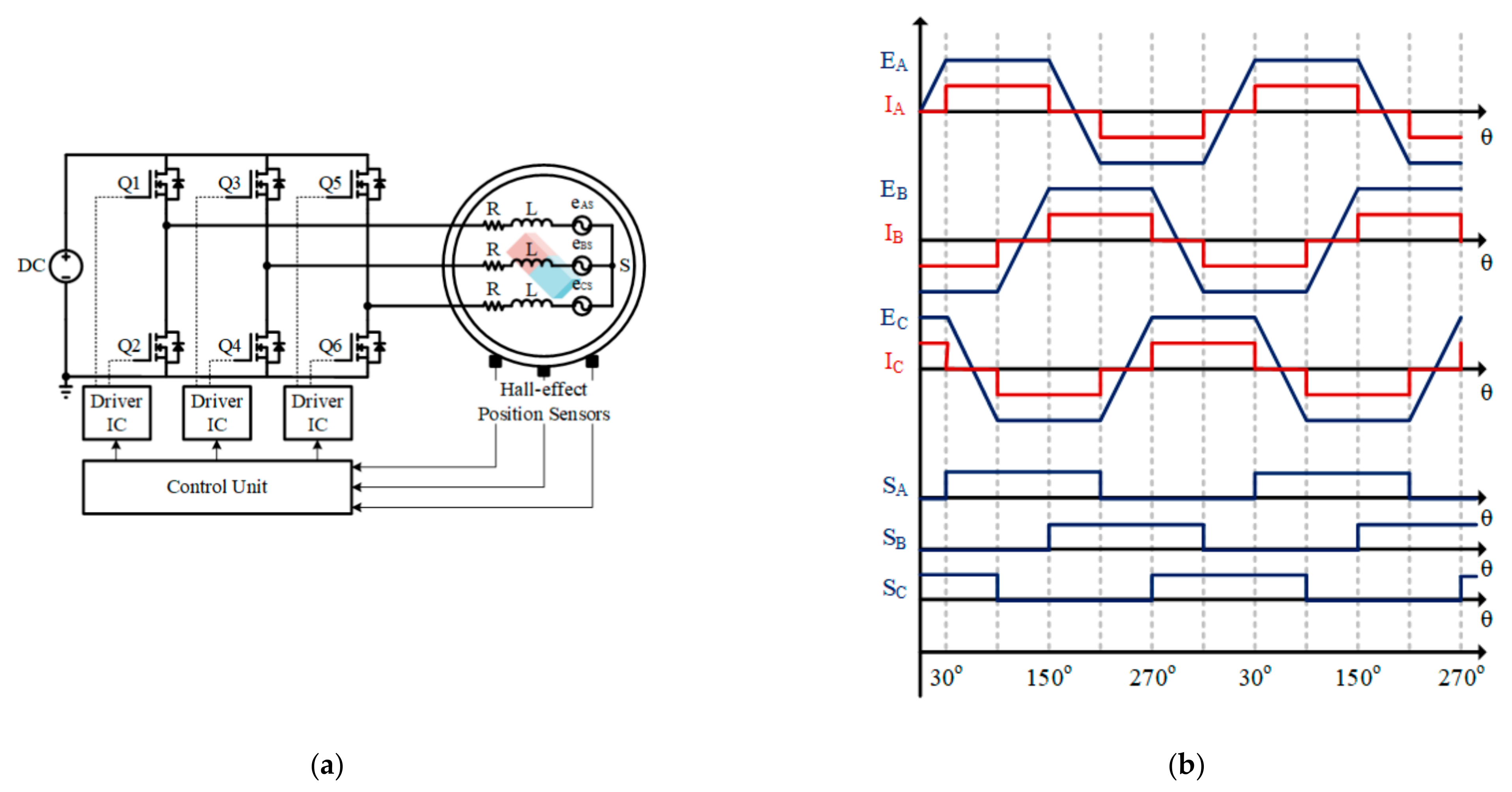
2.1. Brushless DC Motor Drive Operating Principles

The well-known state-space representation of the electric circuit of a BLDC motor with neutral point (s), is expressed by Equations (1) and (2):
V a s V b s V c s = R 0 0 0 R 0 0 0 R · i a i b i c + L s M 0 0 0 L s M 0 0 0 L s M · d d t i a i b i c + e a s e b s e c s ,
e x s = K e ω m f θ r + φ
where R , L s , M , i x (x = a, b, c), e x s , K e , ω m , and f θ denote the phase resistance, self-inductance, mutual inductance, phase current, back-EMF, back-EMF constant, mechanical angular rotor speed, and the trapezoidal function, respectively.
Moreover, the system mechanical dynamic model and the produced electromagnetic torque TE are presented in Equations (3) and (4).
θ ˙ m = ω m ω ˙ m = 1 J · T E T L B ω m ,
Τ E = 1 ω m e a s i a + e b s i b + e c s i c
where θ m , T L , B, and J are the rotor position, load torque, friction torque coefficient, and mechanical inertia, respectively.
Built-in Hall-effect position sensors are usually preferred for BLDC motors, as they offer an implementation of low-cost and volume for rotor position detection with 60° resolution and speed estimation, despite the low update rate of speed at low speeds. More precisely, the digital output of each sensor is high for 180° and low for the rest of the electrical cycle, while the most common configuration consists of three sensors located at 120 electrical degrees apart, dividing the electrical cycle into six sectors. Consequently, a typical BLDC motor drive system, with a voltage source inverter for the electronic motor phase current commutation according to the rotor position, is illustrated in Figure 1a.
Based on the position sensor outputs and the desired rotating direction, the power switches are activated according to a predefined sequence, implementing the standard 120° commutation logic with two active phases at each sector. Thus, each phase is positively energized for 120°, inactive for 60°, negatively energized for 120°, and inactive for the rest of the cycle, as presented in Figure 1b. It is worth noting that the waveforms in this figure are based on the assumptions of negligible turn-on and turn-off times of the power switches and a BLDC motor with ideal trapezoidal back-EMF and low phase inductance. Thus, the controller configuration with respect to the six sectors of one electrical cycle is summarized in Table 1.
However, in practice, the phase currents are characterized by a quasi-rectangular waveform, while in most cases they are not perfectly synchronized with the Back-EMFs, affecting the observed current waveforms. Considering the motor inductances and inevitable detection and processing errors on rotor position estimation, a torque ripple is expected under normal operation of a BLDC motor drive system.

2.2. Use of Piezoelectric Transducers for Position Sensor Faults Detection

According to the direct piezoelectric effect, the application of an external stress in certain crystals gives rise to surface charges producing a polarization, which can be expressed as a voltage difference between the terminals of the crystal. These types of dielectric materials also exhibit a converse effect (converse piezoelectric effect), as they deform and become strain due to the application of an electric potential [34]. More precisely, the direct and the converse piezoelectric effects are expressed by Equations (5) and (6), respectively [35]. As the output voltage polarity is defined by the crystal orientation with respect to the pressure direction, the piezoelectric effect is also graphically presented in Figure 2.
D i = d i k l T k l + ε i k T E k ,
S i j = s i j k l E T k l + d k i j E k
where D i is the electric displacement component, d i k l and d k i j are the piezoelectric coefficients, T k l is the traction vector component, ε i k T is the permittivity component at constant stress, E k is the electric field component, S i j is the strain component, s i j k l E is the elastic compliance constant at constant electric field, and i, j, k, l represent the natural coordinate system of the piezoelectric crystal with values of 1, 2, and 3.
Reliable and durable piezoelectric materials, such as ceramic Zirconate Titanate and polymer Polyvinylidene Fluoride, are commercially available devices and they are favorable for different applications depending on their properties. Considering the Zirconate Titanate ceramics, they are coated with a thin metal film, acting as electrode, forming thin devises of different sizes, where the piezoelectric element is mounted on a circular brass plate (negative electrode) and is coated with a thin metal film (positive electrode). Among the simplest electrical simulators, the Butterworth-Van Dyke (BVD) model, illustrated in Figure 3, is the most popular choice [36]. More precisely, the electronic element Cm is related to the electrode mechanical elasticity, Lm is the inertial component of vibrating material, Rm is the mechanical energy loss due to oscillations, and Co represents the capacitance of a piezoelectric material when the sensor is connected to an electronic circuit. Moreover, a typical piezoelectric sensor sensitivity in sound pressure level (SPL), expressed in dBs in the frequency band of 20 to 20 kHz, is shown in Figure 4. Sensors of these characteristics have been exploited for the experimental investigation, but small differences in the frequency response, due to their low manufacturing cost, can be measured.
Generally, the piezoelectric transducers are based on materials that are able to generate power of nano-Watts to several micro-Watts, resulting in an external input, while the crystal frequency ranges from 0.01 Hz to 1 MHz with temperature range of −270 °C to 650 °C [37]. Thus, the piezoelectric transducers (PZTs) can be exploited in a wide range of applications, such as audible alarms “buzzers”, wireless sensors, nano and micro-electronics for energy harvesting purposes [38,39,40]. In our case, the piezoelectric sensors are placed at appropriate positions on the metal parts of the drive system to acquire vibration signals for fault diagnosis.

2.3. Harmonic Analysis Using the Goertzel Algorithm

Frequency-domain analysis and specifically Fast Fourier Transform (FFT) are well-established in the field of fault diagnosis [41,42]. However, the main FFT analysis drawbacks, such as the limited performance in terms of frequency resolution, spectrum leakage, and computational cost, pushed to the development of advanced signal processing techniques, specified to overcome some of the FFT limitations. The Goertzel algorithm is one of these techniques, considered to be an alternative method in the case of a relatively small number of frequency components of interest [43]. More precisely, the Goertzel algorithm outperforms the FFT by means of the required signal length and the low memory demands, as the computational complexity is independent of the signal length (not a power of two for maximum efficiency) and the computation may be initiated even at the arrival of the first sample. Thus, the Goertzel algorithm has been gaining attention in recent years and it is used in various applications from fault diagnosis and condition monitoring to system control [44,45,46,47,48,49].
The Goertzel algorithm computes the kth Discrete Fourier Transform (DFT) component of the signal x n , which is characterized by a length N as expressed in Equation (7). In addition, the algorithm exploits the periodicity of the phase factor e j 2 π k to reduce the computational complexity, where k is an integer. The resulting first-order difference equation for the desired values of y k n is expressed by Equation (8), containing a complex and computationally expensive multiplication factor. Thus, the second order difference equation is expressed by Equation (9), while in Equation (10) the final system is described [50]. The flow graph of the second order Goertzel algorithm is shown in Figure 5.
X k = n = 0 N 1 x n e j 2 π k n N ,   k = 0 ,     ,   N 1 ,
y k n = x n + e j 2 π k N y k n 1 ,   w i t h   y k 1 = 0 ,
y k n = x n x n 1 e j 2 π k N + 2 cos 2 π k N y k n 1 y k n 2 ,
s n = x n + 2 cos 2 π k N s n 1 s n 2 y k n = s n e j 2 π k N s n 1

3. Investigation of Position Sensor Fault Impact on a BLDC Motor Drive through Simulation

3.1. Simulation Model Development and Healthy System Operation

A simulation model of the drive system was developed to investigate the impact of the position sensor faults on the BLDC motor drive system operation in terms of the DC-link and phase currents, as well as the produced electromagnetic torque. Moreover, the PWM switching frequency was selected at 16 kHz, while the FFT and the Hanning window were used for the harmonic analysis with a frequency resolution of 0.5 Hz. The parameters of a commercially available BLDC motor, which was used for the simulation model and the experimental validation, are summarized in Table 2.
The healthy system behavior is presented in this section for a reference point, which will be used thereafter for the comparison of the investigated signals under the different faulty configurations. Apart from the comparison of the signals between the healthy and the faulty configurations, these results will also be used in the next step with the investigation of the new piezoelectric sensor output signals, according to the vibration pattern under the fault. Thus, the system operation under nominal speed and torque is initially considered and presented in Figure 6. The phase currents are illustrated in Figure 6a, along with the corresponding Back-EMFs, to clearly present the cause of the expected torque ripple. More precisely, the quasi-rectangular phase currents, their non-ideal synchronization with the back-EMF flat top due the phase inductances, and the six-step operation of the motor controller result in an inevitable torque ripple, as it can be observed in Figure 6b, where the electromagnetic torque is presented along with the load torque for the system operation under nominal speed and torque.
On the other hand, these non-idealities can also be detected using frequency-domain analysis of the phase currents, Back-EMFs, DC-link current, or electromagnetic torque signals. The frequency spectra of the previously mentioned signals at rated speed and load are presented in Figure 7. Apart from the dominant fundamental phase current harmonic component, additional components of order n = 5, 7, 11, 13, … can also be observed, while only odd harmonic components are present in the frequency spectrum of the phase back-EMF signal [51,52]. Considering the six-step operation of the three-phase voltage source inverter, the sixth harmonic component is present at the frequency spectra of the DC-link current and electromagnetic torque along with the dominant DC component.

3.2. Brushless DC Motor Drive under Position Sensor Misalignment Fault

Due to manufacturing imperfections, the position sensors can be mounted either with a leading or a lagging position, resulting in a negative or positive commutation angle error, respectively. In the case of a position sensor misalignment, the motor currents and torque will be affected, generating additional vibration signals. Thus, the piezoelectric sensors can be used to diagnose a defective configuration of position sensors with either different or equally shifted non-ideal mounting angles. Nevertheless, the motor behavior under misaligned position sensors and the vibration-based diagnosis concept are not thoroughly investigated in this study, as they have been presented in [33], where the piezoelectric sensors have been successfully used to diagnose position sensor misplacement faults using the second harmonic component of the vibration signals as the fault signature.

3.3. Brushless DC Motor Drive under Position Sensor Breakdown Fault

In this section, the outcome of the single and double position sensor breakdown faults is investigated with respect to the erroneous commutation events, which will be triggered in each case study. Considering an open-loop speed control scenario, each faulty case is presented taking as a reference the system behavior of the healthy case.

3.3.1. Simulation Analysis of Single Position Sensor Breakdown Fault

As already mentioned, the position sensor breakdown fault can be identified by the permanent output signal of the faulty sensor at high or low level, regardless of the rotor position. This faulty condition affects the phase current commutations, as it results to extended sectors of 120° for the active phases, while the “forbidden” vectors of (0,0,0) and (1,1,1) are also observed in the case of a single sensor breakdown fault. It is worth noting that in this study the controller has been programmed to react to a forbidden vector, sending a zero-vector command at the PWM outputs, driving the motor windings to a three-phase floating condition. Therefore, the comparison of the healthy commutation sequence with the defective ones, caused by the two potential states of the defective sensor A, is illustrated in Table 3.
With the standard commutation logic always in mind, the above scenarios related to the defective sensor affect the phase current commutations in a different way for each case, as it can be observed in Figure 8, where the ideal current waveforms (IA, IB, and IC) under healthy operation are compared to the expected (IA’, IB’, and IC’) phase current waveforms, in the presence of a defective position sensor. Back-EMF waveforms (EA, EB, and EC) and position sensor signals (SA, SB, and SC) are also provided for reference and compared to the defective sensor (SA’).
Thus, a single position sensor breakdown fault imposes either additional zero-current sectors or extended conduction periods for active phases, depending on the defective position sensor and its fault state. Although the zero-current sectors derate the average torque output, the increased current values threaten the system, as they may cause a controller power switch failure or increased temperature of the motor windings. It is evident that as the back-EMF amplitude reduces from flat top value to a lower one, the phase current will increase due the input voltage and its voltage difference with the reducing back-EMF. Sequentially, due to the two-phase conduction mode, the other active phase is also affected, and an increased current value is expected for both phases. In addition, these phase currents are not in phase with the corresponding back-EMF and the produced torque ripple will increase, which should be an additional concern for system stability. In the case of a different position sensor breakdown fault, similar waveforms are expected according to the defective sensor and its state at the fault.
The impact of the single position sensor breakdown fault on system operation has been simulated and characteristic results are demonstrated. Thus, the DC-link and the phase currents can be observed in Figure 9 for the scenario of Hall A at a permanent high level and low level, Figure 9a,b respectively, where it is evident that the position sensor fault results in high distortion of the DC-link and the phase currents. This distortion sequentially affects the torque ripple, as it illustrated in Figure 10 for both cases.
Comparing the initially presented results of Figure 8 to the open-loop speed control simulation results, it is evident that the system inductances are highly affecting the waveforms of the phase currents. In addition, an increased value of the circulating current between the motor windings can also be observed for the defective configuration, furtherly affecting the observed current peaks. The erroneous rotor position feedback is responsible both for the negative and the high positive electromagnetic torque values, as the faulty rotor position feedback results to either an extended conduction period of the active phases, pulling the rotor backwards, or to an earlier commutation event, pulling the rotor forward by skipping a sector. It is also evident that position sensor faults of the other two Hall-effect sensors provide similar results.
Examining the frequency-domain analysis, the impact of the investigated position sensor A breakdown fault is presented in Figure 11, where a high distortion of the investigated signal frequency spectra can be observed. Although the second harmonic component can also be used to detect a position sensor breakdown fault, as in the case of the sensor misplacement fault, the fourth harmonic component is preferred here as the fault signature, to distinguish these fault types. Considering that the mechanical power produced by the motor can be expressed by Equation (11), it is obvious that the torque harmonic component is expected to contain the same frequencies as the DC-link current. Therefore, specific harmonic components of the vibration signals, highly related to the phase currents, the DC-link current, and the electromagnetic torque, will be investigated in the next section as the position sensor breakdown fault signatures.
P m = T m · ω m = P i n P l o s s e s = V D C · I D C P l o s s e s  
where P m is the motor mechanical output power, T m is the motor output torque, ω m is the mechanical angular rotor speed, P i n is the input source power, P l o s s e s is the system total power losses, V D C is the DC-link constant voltage, and I D C is the DC-link current.

3.3.2. Simulation Analysis of Double Position Sensor Breakdown Fault

The double position sensor fault is an extremely rare condition, as there is no point of maintaining the drive system operation with one faulty position sensor detected. Nevertheless, the double position sensor fault is investigated by several studies in the literature to highlight their capability of detecting both types of the position sensor breakdown fault [26,27]. Thus, the double sensor fault is also considered in this study and a comparison of the healthy commutation sequence with the defective one for each case of a double breakdown fault of position sensors A and C is presented in Table 4 and Table 5.
These faulty configurations affect the phase currents, as extended zero-current sectors are now observed for the cases of the same faulty state of the defective position sensors, while extended conduction periods are also expected for the rest cases of faulty sensors with a different state. However, these erroneous extended conducting periods will result in enormous current and torque oscillations, which apart from the system stability may have devastating consequences for the system parts, triggering an avalanche phenomenon due to the high phase current values. Despite being a rare fault type, the double position sensor breakdown fault is investigated here as a simultaneous fault at a low speed and load system operating point, where the impacts of the double fault will not result in an immediate system failure, so fault diagnosis implementation is meaningful. In these low-profile failure modes, the condition monitoring aims to prevent catastrophic failures at a higher system level, when an increased output power will be requested to the defective, but still operating, drive system. Due to the expected system instability, only the cases of the same defective sensor outputs are considered thereafter, as they incorporate zero-current vectors and result in a more stable operation compared to the other two cases. The cases for both sensor output signals at high and low levels are also presented in Figure 12, respectively, where the simplified/ideal current waveforms (IA, IB, and IC) are compared to the resulting (IA’, IB’, and IC’) phase current waveforms, according to each defective configuration caused by the faulty sensors (SA’ and SB’). Back-EMF waveforms (EA, EB, and EC) and position sensor signals (SA, SB, and SC) are also provided for reference.
Due to the severity of the simultaneous double fault, a low speed and load operating point will be exploited for the simulation investigation. Although a no-load condition could be selected, an arbitrary load of 10% of the rated load was preferred to highlight the severity of the fault type by the observed high current values. Thus, a scenario of relatively low speed (900 rpm) and 10% of the rated load is considered for the following simulation analysis. Despite the differences, the currents in Figure 13 share a similar pattern of phase current switching only between two states. In addition, the circulating current through the freewheeling diodes can clearly be observed, as the controller phase C should be inactive under the double fault, as previously described in Figure 12.
Despite the different impact of the double fault on the electromagnetic torque waveform, observed in Figure 14, the frequency-domain analysis results to a similar frequency spectrum for the electromagnetic torque as in the previous case, which is also verified for the DC-link and the phase current frequency spectra in Figure 15. Consequently, a double position sensor fault is expected to generate vibration signals with specific harmonic components, related to the investigated phase currents, DC-link current, and electromagnetic torque frequency spectra.

4. Experimental Investigation of the Proposed Fault-Detection Methodology

4.1. Development of the Experimental Setup

A three-phase voltage source inverter (VSI) was developed to drive a series of low voltage BLDC motors and it is exploited here to drive the BLDC motor of Table 2. In addition, multiple piezoelectric transducers, noted here as PSx, where x = A, B, …, I, have been mounted on the experimental setup. As the performance of the piezoelectric transducers in detecting different fault types of BLDC motor drive systems is investigated, multiple sensors have been mounted on various positions on the experimental setup. However, this study is focused on Hall-effect position sensor faults and signals acquired only from one piezoelectric sensor, namely PSI, have been used and proven adequate for the fault diagnosis. Moreover, an Internet-of-Things (IoT) multi-sensory analog processing module has also been developed to acquire the signals of the piezoelectric sensors. Thus, the experimental setup of the BLDC drive system is presented in Figure 16, while several piezoelectric transducers can be observed in Figure 17a,b and the multi-sensory module is presented in Figure 17c.
This module includes a set of seven active first-order low pass filters at 5 kHz, implemented using two ICs of a single supply, low-cost, noise, and offset general purpose operational amplifier. The analog channels are sampled and digitized at 10 kHz and 12 bits accuracy, pre-processed, and wirelessly transferred to the base computing system using the UTP communication protocol. The complete system is implemented in the extremely low cost, low power, and high performance ESP32, Wi-Fi-and-Bluetooth chip. The ESP32 is designed for mobile, wearable electronics, and Internet-of-Things (IoT) applications containing two Analog-to-Digital Converters (ADC), two low-power Xtensa® 32-bit LX6 microprocessors, and a third very low power consumption Reduced Instruction Set Computer (RISC) processor. One Xtensa processor handles the sequence of analog channels acquisition process using the first ADC (the second ADC is used by the WiFi module), and the second Xtensa processor is used to control the WiFi module, to prepare the UTP packets and to transmit the multi-channel digital signals to the desired IP address through a Wi-Fi channel.
The proposed fault diagnosis method is summarized in the flowchart of Figure 18, where the detection of a second harmonic component triggers the fault diagnosis process to identify a potential misalignment defect or a breakdown fault, whereas the fourth harmonic component increment distinguishes between the two fault types.

4.2. Piezoelectric Sensor Investigation under Position Sensor Misalignment Defect

Τhe piezoelectric sensors can be exploited for the diagnosis of the position sensor misalignment, as previously proven in [33], where the piezoelectric sensors have been used to diagnose a defective configuration of position sensors with either different or equally shifted non-ideal mounting angles. Therefore, the second harmonic component of the piezoelectric sensor frequency spectra has already been used for the position sensor misalignment defect diagnosis and characteristic results of the piezoelectric sensor PSI output signal are illustrated in Figure 19 for the case of system operation at about 900 rpm (60 Hz fundamental frequency), 65% of the rated torque, and a single misaligned position sensor.

4.3. Piezoelectric Sensor Investigation under a Single Position Sensor Breakdown Fault

For the investigation of the single position sensor breakdown fault, a Hall-effect position sensor was considered to be faulty, continually reporting either a high or a low output signal. As the first step of the experimental investigation, the phase currents are presented in Figure 20, to compare the healthy case with the two defective configurations of Hall-effect position sensor A breakdown fault at high and low, respectively. Despite the system operation at low speed and power (900 rpm and no load), the observed phase current peak values highlight the severity of the fault and the need to be detected at an early state prior to motor loading. It is worth noting that the previously presented results, by the simulation model investigation for the single position sensor breakdown fault, are related to the system nominal power operation, as these simulation results were also compared to the initially presented healthy system operation. Despite the speed and load dependent differences, the phase current waveforms of the simulation at nominal power share a similar pattern with the phase current waveforms acquired during the experimental procedure.
Moreover, the piezoelectric sensor PSI output signals and the fault signatures in case of position sensor breakdown fault at permanent high and low state are presented Figure 21, respectively. As previously mentioned, both experiments were conducted with rotor speed at 900 rpm, fundamental frequency of 60 Hz, and no load. Comparing the frequency spectra of the healthy and defective configurations, the second harmonic component of the piezoelectric senor output can be used as a fault signature for both cases. However, it would be advantageous if another frequency was used to indicate the breakdown fault, enabling the distinction between misalignment defect and breakdown. More precisely, the breakdown fault signature can be detected at the even harmonic components and, consequently, the fourth harmonic component of the piezoelectric sensor output signal can be exploited for the breakdown fault diagnosis, compared to the single second harmonic component in case of misalignment fault. Therefore, the second harmonic component can be monitored for the position sensor generic fault presence and the fourth harmonic component to distinguish a potential breakdown fault.
In addition, the Goertzel algorithm can be exploited for the frequency-domain analysis using only a narrow frequency band around the harmonic component of interest, instead of the whole frequency spectrum as in case of the FFT analysis, making possible the online implementation of the methodology. It is worth noting that the results with the Goertzel algorithm are presented without being normalized, as there is no other harmonic component of high amplitude in the investigated frequency spectrum range, which can also be further narrowed for faster implementation.

4.4. Piezoelectric Sensor Investigation under a Double Position Sensor Breakdown Fault

For the double position sensor breakdown fault, the cases of both position sensors continuously reporting the same high or low signal were investigated. The same operating condition of 900 rpm at no load was used for the double position sensor fault. Therefore, the phase currents are presented in Figure 22 to compare the healthy case with the two defective configurations of double Hall-effect position sensor breakdown fault, both at high and low states, respectively. The experimental results of the phase current waveforms coincide with the initial simulation results, as the zero-current vectors, due to the double position sensor breakdown fault, impose a zero-current controlled conduction for one motor phase, affecting the motor stator vibrations and the corresponding piezoelectric sensor output signals and frequency spectra. As both simulation and experimental results have been acquired at the same system operating conditions, the small differences between the phase current waveforms are related to the nonideality of the motor back-EMF.
Finally, the piezoelectric sensor outputs and fault signatures are presented in Figure 23 for both defective position sensors at permanent high level and both position sensors at permanent low level, respectively. Although the frequency spectra are richer under double faults, the increment of the fourth harmonic component, compared to the healthy configuration, is also verified in all cases enabling the development of a generic approach, based on a specific harmonic component for position sensor breakdown fault diagnosis in BLDC motor drives. Furthermore, the Goertzel algorithm exploitation is still valid in this case, too.

5. Conclusions

In this study, an alternative, non-invasive, Hall-effect position sensor faults monitoring method for brushless DC motor drives is presented. The method is based on the analysis of motor vibration signals and the use of piezoelectric sensors is proposed as a low-cost implementation for the diagnosis or as a part of a smart sensor with the ability to analyze the acquired data, provide a fault alarm, and initiate an emergency system stop.
More precisely, the Hall-effect position sensor misalignment and breakdown faults are investigated, extending the previous study, where the piezoelectric sensors have been used for the diagnosis of the position sensor misalignment fault only. The system performance in the case of a position sensor breakdown fault was also considered, presenting the impact on the DC-link, the phase currents, and the electromagnetic torque, to highlight the differences to the healthy case. In addition, the torque and speed oscillations are also investigated, as they will be responsible for the stator vibrations.
The main advantage of the proposed method is its ability to distinguish between the two position sensor fault types, as different harmonic components are monitored for each case. As the fault signatures are localized in well-defined harmonic components, the Goertzel algorithm is also proposed for the harmonic analysis in a narrow band, saving computational costs and memory demands in the case of online implementation. From the analysis as well as the experimental results, it is concluded that the piezoelectric sensors could be used in the field of condition monitoring of electric motor drive systems, forming a smart IoT sensor for inexpensive fault diagnosis.

Author Contributions

Investigation, D.A.P., K.N.G., E.S.D. and E.D.M.; Methodology, D.A.P., K.N.G., E.S.D. and E.D.M. All authors contributed to this paper. All authors have read and agreed to the published version of the manuscript.

Funding

This research is co-financed by Greece and the European Union (European Social Fund—ESF) through the Operational Programme «Human Resources Development, Education and Lifelong Learning 2014–2020» in the context of the project under MIS number 5047162.

Conflicts of Interest

The authors declare no conflict of interest.

References

  1. Nandi, S.; Toliyat, H.A.; Li, X. Condition Monitoring and Fault Diagnosis of Electrical Motors—A Review. IEEE Trans. Energy Convers. 2005, 20, 719–729. [Google Scholar] [CrossRef]
  2. Dyer, D.; Stewart, R.M. Detection of Rolling Element Bearing Damage by Statistical Vibration Analysis. J. Mech. Des. 1978, 100, 229–235. [Google Scholar] [CrossRef]
  3. Henriquez, P.; Alonso, J.B.; Ferrer, M.A.; Travieso, C.M. Review of Automatic Fault Diagnosis Systems Using Audio and Vibration Signals. IEEE Trans. Syst. Man Cybern. Syst. 2014, 44, 642–652. [Google Scholar] [CrossRef]
  4. Kanović, Ž.; Matić, D.; Jeličić, Z.; Rapaić, M.; Jakovljević, B.; Kapetina, M. Induction Motor Broken Rotor Bar Detection Using Vibration Analysis—A Case Study. In Proceedings of the 2013 9th IEEE International Symposium on Diagnostics for Electric Machines, Power Electronics and Drives (SDEMPED), Valencia, Spain, 27–30 August 2013; pp. 64–68. [Google Scholar] [CrossRef]
  5. Zimnickas, T.; Vanagas, J.; Dambrauskas, K.; Kalvaitis, A. A Technique for Frequency Converter-fed Asynchronous Motor Vibration Monitoring and Fault Classification, Applying Continuous Wavelet Transform and Convolutional Neural Networks. Energies 2020, 13, 3690. [Google Scholar] [CrossRef]
  6. Sizov, G.Y.; Yeh, C.; Demerdash, N.A.O. Application of Piezoelectric Sensors to Rotor Fault Diagnostics in Squirrel-Cage Induction Machines. In Proceedings of the 2008 the IEEE Industry Applications Society Annual Meeting, Edmonton, AB, Canada, 5–9 October 2008; pp. 1–6. [Google Scholar] [CrossRef]
  7. Minervini, M.; Frosini, L.; Hasani, L.; Albini, A. A Multisensor Induction Motors Diagnostics Method for Bearing Cyclic Fault. In Proceedings of the 2020 International Conference on Electrical Machines (ICEM), Gothenburg, Sweden, 23–26 August 2020; Volume 1, pp. 1259–1265. [Google Scholar] [CrossRef]
  8. Lucas, G.; Rocha, M.; Castro, B.; Leão, J.; Andreoli, A. Stator Winding Fault Phase Identification Using Piezoelectric Sensors in Three-Phase Induction Motors. Eng. Proc. 2020, 2, 32. [Google Scholar] [CrossRef]
  9. Yoon, J.; He, D.; Van Hecke, B. On the Use of a Single Piezoelectric Strain Sensor for Wind Turbine Planetary Gearbox Fault Diagnosis. IEEE Trans. Ind. Electron. 2015, 62, 6585–6593. [Google Scholar] [CrossRef]
  10. Gama, L.; de Lima, W.B.; de Veneza, J.P.S. Detection of Shaft Misalignment Using Piezoelectric Strain Sensors. Exp. Tech. 2017, 41, 87–93. [Google Scholar] [CrossRef]
  11. Lucas, G.B.; de Castro, B.A.; Rocha, M.A.; Andreoli, A.L. Study of a Low-Cost Piezoelectric Sensor for Three Phase Induction Motor Load Estimation. Proceedings 2019, 4, 46. [Google Scholar] [CrossRef] [Green Version]
  12. Carvalho, L.; Lucas, G.; Rocha, M.; Fraga, C.; Andreoli, A. Undervoltage Identification in Three Phase Induction Motor Using Low-Cost Piezoelectric Sensors and STFT Technique. Proceedings 2020, 42, 72. [Google Scholar] [CrossRef] [Green Version]
  13. Iorgulescu, M.; Alexandru, M.; Beloiu, R. Noise and Vibration Monitoring for Diagnosis of DC Motor’s Faults. In Proceedings of the 2012 13th International Conference on Optimization of Electrical and Electronic Equipment (OPTIM), Brasov, Romania, 24–26 May 2012; pp. 724–729. [Google Scholar] [CrossRef]
  14. Zimnickas, T.; Vanagas, J.; Dambrauskas, K.; Kalvaitis, A.; Ažubalis, M. Application of Advanced Vibration Monitoring Systems and Long Short-Term Memory Networks for Brushless DC Motor Stator Fault Monitoring and Classification. Energies 2020, 13, 820. [Google Scholar] [CrossRef] [Green Version]
  15. Shifat, T.A.; Hur, J.W. An Effective Stator Fault Diagnosis Framework of BLDC Motor Based on Vibration and Current Signals. IEEE Access 2020, 8, 106968–106981. [Google Scholar] [CrossRef]
  16. Long, B.; Lim, S.T.; Ryo, J.H.; Chong, K.T. Energy-Regenerative Braking Control of Electric Vehicles Using Three-Phase Brushless Direct-Current Motors. Energies 2014, 7, 99–114. [Google Scholar] [CrossRef] [Green Version]
  17. Nandakumar, M.; Ramalingam, S.; Nallusamy, S.; Rangarajan, S.S. Hall-Sensor-Based Position Detection for Quick Reversal of Speed Control in a BLDC Motor Drive System for Industrial Applications. Electronics 2020, 9, 1149. [Google Scholar] [CrossRef]
  18. Huang, X.; Goodman, A.; Gerada, C.; Fang, Y.; Lu, Q. A Single Sided Matrix Converter Drive for a Brushless DC Motor in Aerospace Applications. IEEE Trans. Ind. Electron. 2012, 59, 3542–3552. [Google Scholar] [CrossRef]
  19. Tashakori, A.; Ektesabi, M. A Simple Fault Tolerant Control System for Hall Effect Sensors Failure of BLDC Motor. In Proceedings of the 2013 IEEE 8th Conference on Industrial Electronics and Applications (ICIEA), Melbourne, Australia, 19–21 June 2013; pp. 1011–1016. [Google Scholar] [CrossRef]
  20. Mitronikas, E.; Papathanasopoulos, D.; Athanasiou, G.; Tsotoulidis, S. Hall-effect Sensor Fault Identification in Brushless DC Motor Drives Using Wavelets. In Proceedings of the 2017 IEEE 11th International Symposium on Diagnostics for Electrical Machines, Power Electronics and Drives (SDEMPED), Tinos, Greece, 29 August–1 September 2017; pp. 434–440. [Google Scholar] [CrossRef]
  21. Gowtham, S.; Keerthana, I.; Balaji, M. Characterization and Classification of Hall Sensor Faults using S-Transform Analysis on BLDC Motor Drive. In Proceedings of the 2019 IEEE 1st International Conference on Energy, Systems and Information Processing (ICESIP), Chennai, India, 4–6 July 2019; pp. 1–6. [Google Scholar] [CrossRef]
  22. Skóra, M.; Kowalski, C.T. The Influence of Sensor Faults on PM BLDC Motor Drive. In Proceedings of the 2015 International Conference on Electrical Drives and Power Electronics (EDPE), Tatranska Lomnica, Slovakia, 21–23 September 2015; pp. 1–6. [Google Scholar] [CrossRef]
  23. Selmi, T.; Baitie, H.E.; Masmoudi, A. An Approach to Diagnose and Remediate Failures of Hall Effect Sensors in BLDC Motors. In Proceedings of the 2015 International Conference on Sustainable Mobility Applications, Renewables and Technology (SMART), Kuwait, Kuwait, 23–25 November 2015; pp. 1–7. [Google Scholar] [CrossRef]
  24. Sova, V.; Chalupa, J.; Grepl, R. Fault Tolerant BLDC Motor Control for Hall Sensors Failure. In Proceedings of the 2015 21st International Conference on Automation and Computing (ICAC), Glasgow, UK, 11–12 September 2015; pp. 1–6. [Google Scholar] [CrossRef]
  25. Mehta, H.; Thakar, U.; Joshi, V.; Rathod, K.; Kurulkar, P. Hall Sensor Fault Detection and Fault Tolerant Control of PMSM Drive System. In Proceedings of the 2015 International Conference on Industrial Instrumentation and Control (ICIC), Pune, India, 28–30 May 2015; pp. 624–629. [Google Scholar] [CrossRef]
  26. Scelba, G.; De Donato, G.; Scarcella, G.; Capponi, F.G.; Bonaccorso, F. Fault-Tolerant Rotor Position and Velocity Estimation Using Binary Hall-Effect Sensors for Low-Cost Vector Control Drives. IEEE Trans. Ind. Appl. 2014, 50, 3403–3413. [Google Scholar] [CrossRef]
  27. Scelba, G.; De Donato, G.; Pulvirenti, M.; Capponi, F.G.; Scarcella, G. Hall-Effect Sensor Fault Detection, Identification, and Compensation in Brushless DC Drives. IEEE Trans. Ind. Appl. 2016, 52, 1542–1554. [Google Scholar] [CrossRef]
  28. Dong, L.; Huang, Y.; Jatskevich, J.; Liu, J. Improved Fault-Tolerant Control for Brushless Permanent Magnet Motor Drives With Defective Hall Sensors. IEEE Trans. Energy Convers. 2016, 31, 789–799. [Google Scholar] [CrossRef]
  29. Zhang, Q.; Feng, M. Fast Fault Diagnosis Method for Hall Sensors in Brushless DC Motor Drives. IEEE Trans. Power Electron. 2019, 34, 2585–2596. [Google Scholar] [CrossRef]
  30. Papathanasopoulos, D.A.; Mitronikas, E.D. Fault Tolerant Control of a Brushless DC Motor with Defective Position Sensors. In Proceedings of the 2018 XIII International Conference on Electrical Machines (ICEM), Alexandroupoli, Greece, 3–6 September 2018; pp. 1503–1509. [Google Scholar] [CrossRef]
  31. Mousmi Abbou, A.; El Houm, Y. Binary Diagnosis of Hall Effect Sensors in Brushless DC Motor Drives. IEEE Trans. Power Electron. 2020, 35, 3859–3868. [Google Scholar] [CrossRef]
  32. Aqil, M.; Hur, J. A Direct Redundancy Approach to Fault-Tolerant Control of BLDC Motor with a Damaged Hall-Effect Sensor. IEEE Trans. Power Electron. 2020, 35. [Google Scholar] [CrossRef]
  33. Papathanasopoulos, D.A.; Mitronikas, E.D.; Giannousakis, K.N.; Dermatas, E.S. An Alternative Approach for Condition Monitoring of Brushless DC Motor Drives. In Proceedings of the 2020 International Conference on Electrical Machines (ICEM), Gothenburg, Sweden, 23–26 August 2020; Volume 1, pp. 1280–1286. [Google Scholar] [CrossRef]
  34. Kasap, S. Principles of Electronic Materials and Devices, 3rd ed.; Tata McGraw-Hill: New Delhi, Delhi, India, 2005. [Google Scholar]
  35. De Freitas, E.S.; Baptista, F.G.; Budoya, D.E.; de Castro, B.A. Equivalent Circuit of Piezoelectric Diaphragms for Impedance-Based Structural Health Monitoring Applications. IEEE Sens. J. 2017, 17, 5537–5546. [Google Scholar] [CrossRef] [Green Version]
  36. Svilainis, L.; Dumbrava, V.; Motiejunas, G. Optimization of the Ultrasonic Excitation Stage. In Proceedings of the ITI 2008—30th International Conference on Information Technology Interfaces, Cavtat, Croatia, 23–26 June 2008. [Google Scholar]
  37. Elahi, H.; Munir, K.; Eugeni, M.; Abrar, M.; Khan, A.; Arshad, A.; Gaudenzi, P. A Review on Applications of Piezoelectric Materials in Aerospace Industry. Integr. Ferroelectr. 2020, 211, 25–44. [Google Scholar] [CrossRef]
  38. Shaikh, F.K.; Zeadally, S. Energy Harvesting in Wireless Sensor Networks: A Comprehensive Review. Renew. Sustain. Energy Rev. 2016, 55, 1041–1054. [Google Scholar] [CrossRef]
  39. Saoutieff, E.; Allain, M.; Nowicki-Bringuier, Y.-R.; Viana, A.; Pauliac-Vaujour, E. Integration of Piezoelectric Nanowires Matrix onto a Microelectronics Chip. Procedia Eng. 2016, 168, 1638–1641. [Google Scholar] [CrossRef]
  40. Yuan, T.-C.; Yang, J.; Chen, L.-Q. Nonlinear Dynamics of a Circular Piezoelectric Plate for Vibratory Energy Harvesting. Commun. Nonlinear Sci. Numer. Simul. 2018, 59, 651–656. [Google Scholar] [CrossRef]
  41. Kia, S.H.; Henao, H.; Capolino, G.-A. Efficient Digital Signal Processing Techniques for Induction Machines Fault Diagnosis. In Proceedings of the IEEE Workshop on Electrical Machines Design, Control and Diagnosis (WEMDCD), Paris, France, 11–12 March 2013; pp. 232–246. [Google Scholar] [CrossRef]
  42. Filippetti, F.; Bellini, A.; Capolino, G.-A. Condition Monitoring and Diagnosis of Rotor Faults in Induction Machines: State of Art and Future Perspectives. In Proceedings of the IEEE Workshop on Electrical Machines Design, Control and Diagnosis (WEMDCD), Paris, France, 11–12 March 2013; pp. 196–209. [Google Scholar] [CrossRef]
  43. Papathanasopoulos, D.A.; Spyropoulos, D.V.; Mitronikas, E.D. Fault Diagnosis of Misaligned Hall-effect Position Sensors in Brushless DC Motor Drives Using a Goertzel Algorithm. In Proceedings of the IEEE 12th International Symposium on Diagnostics for Electrical Machines, Power Electronics and Drives (SDEMPED), Toulouse, France, 27–30 August 2019; pp. 167–173. [Google Scholar] [CrossRef]
  44. Peña-Alzola, R.; Sztykiel, M.; Jones, C.E.; Norman, P.J.; Moore, G.; Pou, J.; Burt, G.M. First-Fault Detection in DC Distribution with IT Grounding Based on Sliding Discrete Fourier-Transform. IEEE Trans. Power Electron. 2021, 36, 3649–3654. [Google Scholar] [CrossRef]
  45. Papathanasopoulos, D.A.; Spyropoulos, D.V.; Mitronikas, E.D.; Karlis, A.D. Commutation Angle Self-Calibrating Technique for Brushless DC Motor Drives with Defective Hall-effect Position Sensors. In Proceedings of the 2020 International Conference on Electrical Machines (ICEM), Gothenburg, Sweden, 23–26 August 2020; Volume 1, pp. 1301–1307. [Google Scholar] [CrossRef]
  46. Spyropoulos, D.V.; Mitronikas, E.D.; Dermatas, E.S. Broken Rotor Bar Fault Diagnosis in Induction Motors Using a Goertzel Algorithm. In Proceedings of the 2018 XIII International Conference on Electrical Machines (ICEM), Alexandroupoli, Greece, 3–6 September 2018; pp. 1782–1788. [Google Scholar] [CrossRef]
  47. Sundararajan, P.; Sathik, M.H.M.; Sasongko, F.; Tan, C.S.; Pou, J.; Blaabjerg, F.; Gupta, A.K. Condition Monitoring of DC-Link Capacitors Using Goertzel Algorithm for Failure Precursor Parameter and Temperature Estimation. IEEE Trans. Power Electron. 2020, 35, 6386–6396. [Google Scholar] [CrossRef]
  48. Song, X.; Wang, Z.; Li, S.; Hu, J. Sensorless Speed Estimation of an Inverter-Fed Induction Motor Using the Supply-Side Current. IEEE Trans. Energy Convers. 2019, 34, 1432–1441. [Google Scholar] [CrossRef]
  49. Singh, B.; Reddy, C.C. Fast Goertzel Algorithm and RLS-Adaptive Filter Based Reference Current Extraction for Grid-Connected System. In Proceedings of the 2020 IEEE PES Innovative Smart Grid Technologies Europe (ISGT-Europe), The Hague, The Netherlands, 26–28 October 2020; pp. 156–160. [Google Scholar] [CrossRef]
  50. Sysel, P.; Rajmic, P. Goertzel Algorithm Generalized to Non-Integer Multiples of Fundamental Frequency. EURASIP J. Adv. Signal Process. 2012, 1–8. [Google Scholar] [CrossRef] [Green Version]
  51. Papathanasopoulos, D.A.; Mitronikas, E.D. Diagnosis of Defective Hall-effect Position Sensors in Brushless DC Motor Drives. In Proceedings of the IEEE Workshop on Electrical Machines Design, Control and Diagnosis (WEMDCD), Athens, Greece, 22–23 April 2019; pp. 137–142. [Google Scholar] [CrossRef]
  52. Papathanasopoulos, D.A.; Mitronikas, E.D. Evaluation of the Virtual Third Harmonic Back-EMF in Identifying Misaligned Hall-effect Position Sensors in Brushless DC Motor Drives. In Proceedings of the IEEE 12th International Symposium on Diagnostics for Electrical Machines, Power Electronics and Drives (SDEMPED), Toulouse, France, 27–30 August 2019; pp. 181–187. [Google Scholar] [CrossRef]
Figure 1. (a) Block diagram of a typical brushless DC motor drive with built-in Hall-effect position sensors, (b) Ideal waveforms of the Back-EMFs (Ex) and the phase currents (Ix) according to the Hall-effect position sensor signals (Sx) and the rotor position, where x = A, B, and C.
Energies 14 02248 g001
Figure 2. Simplified diagram of the direct and converse piezoelectric effect outcome (blue) due to different mechanical or electrical causes (red).
Energies 14 02248 g002
Figure 3. Butterworth-Van Dyke electrical model of a piezoelectric sensor.
Energies 14 02248 g003
Figure 4. Typical piezoelectric sensor sensitivity in sound pressure level.
Energies 14 02248 g004
Figure 5. Block diagram of the second order Goertzel algorithm.
Energies 14 02248 g005
Figure 6. Healthy case: (a) Phase currents and back-EMF voltage waveforms at rated speed and load, (b) DC-link current, Electromagnetic (TE) and load torque (TL) at rated speed and load.
Energies 14 02248 g006
Figure 7. Healthy motor operation at rated speed and load: (a) Frequency spectrum of phase A current; (b) Frequency spectrum of phase A back-EMF; (c) Frequency spectrum of the DC-link current; (d) Frequency spectrum of electromagnetic torque.
Energies 14 02248 g007
Figure 8. Comparison of ideal and resulting phase current waveforms according to the defective position sensor state. (a) Defective sensor A at high state; (b) Defective sensor A at low state.
Energies 14 02248 g008
Figure 9. Phase currents and back-EMF voltages along with the DC-link current in case of rated speed and load under Hall-effect position sensor A failure. (a) Defective sensor A at high state; (b) Defective sensor A at low state.
Energies 14 02248 g009
Figure 10. Electromagnetic torque TE compared to the load torque TL in case of rated speed and load under Hall-effect position sensor A breakdown fault: (a) Defective sensor A at high state, (b) Defective sensor A at low state.
Energies 14 02248 g010
Figure 11. Comparison of phase current, DC-link current, and electromagnetic torque frequency spectra in case of rated speed and load operating point for the healthy and defective configuration of Hall-effect position sensor A breakdown fault. (a) Defective sensor A at high state; (b) Defective sensor A at low state.
Energies 14 02248 g011
Figure 12. Comparison of ideal and resulting phase current waveforms according to the defective configuration. (a) Defective sensors A and C at high state; (b) Defective sensors A and C at low state.
Energies 14 02248 g012
Figure 13. Phase currents and back-EMF voltages along with the DC-link current in case of 900 rpm and 10% of rated load under Hall-effect position sensors A and C double failure. (a) Defective sensors A and C at high state; (b) Defective sensors A and C at low state.
Energies 14 02248 g013
Figure 14. Electromagnetic torque TE compared to the load torque TL in case of 900 rpm and 10% of rated load under Hall-effect position sensors A and C breakdown fault. (a) Defective sensors A and C at high state; (b) Defective sensors A and C at low state.
Energies 14 02248 g014
Figure 15. Comparison of phase current, DC-link current, and electromagnetic torque frequency spectra in case of 900 rpm and 10% of rated load operating point for the healthy and defective configuration of Hall-effect position sensors A and C breakdown fault. (a) Defective sensors A and C at high state; (b) Defective sensors A and C at low state.
Energies 14 02248 g015
Figure 16. Experimental setup of the developed BLDC motor drive system.
Energies 14 02248 g016
Figure 17. Piezoelectric sensors mounted on the BLDC motor and mounting base. (a) Left view; (b) Front view; (c) Top (ESP32 module) and bottom side (filters) of the Internet-of-Things (IoT) multi-sensory analog processing module.
Energies 14 02248 g017
Figure 18. Flowchart of the proposed method for the position sensor fault diagnosis through vibration analysis.
Energies 14 02248 g018
Figure 19. Investigation of position sensor misalignment defect at 910 rpm, 65% of rated torque, and single defective position sensor. (a) Waveform of piezoelectric sensor PSI output, (b) Frequency spectrum of piezoelectric sensor PSI output, (c) Narrow frequency spectrum of piezoelectric sensor PSI with Goertzel analysis.
Energies 14 02248 g019aEnergies 14 02248 g019b
Figure 20. Experimental investigation of motor phase currents under single position sensor breakdown fault. System operation at 900 rpm and no load in case of healthy and defective configurations. (a) Waveform of phase currents at healthy configuration; (b) Waveform of phase currents at defective configuration of position sensor A at high state; (c) Waveform of phase currents at defective configuration of position sensor A at low state.
Energies 14 02248 g020aEnergies 14 02248 g020b
Figure 21. Experimental Investigation of position sensor A breakdown fault at permanent (a) high state and (b) low state for motor operation at 900 rpm and no-load operation using piezoelectric sensor. From top to bottom: Waveform of piezoelectric sensor PSI output, Frequency spectrum and Narrow frequency spectrum using Goertzel analysis.
Energies 14 02248 g021
Figure 22. Experimental investigation of motor phase currents under double position sensor breakdown fault. System operation at 900 rpm and no load in case of healthy and defective configurations. (a) Waveform of phase currents at healthy configuration; (b) Waveform of phase currents at defective configuration of position sensor A at high state; (c) Waveform of phase currents at defective configuration of position sensor A at low state.
Energies 14 02248 g022
Figure 23. Experimental Investigation of position sensors A and C breakdown fault at permanent (a) high state and (b) low state for motor operation at 900 rpm and no-load operation using piezoelectric sensor. From top to bottom: Waveform of piezoelectric sensor PSI output, Frequency spectrum and Narrow frequency spectrum using Goertzel analysis.
Energies 14 02248 g023
Table 1. The 120° commutation logic according to rotor position and the sensor signals.
SectorSensor ASensor BSensor CActive SwitchesActive Windings
a101Q1, Q4A+, B−
b100Q1, Q6A+, C−
c110Q3, Q6B+, C−
d010Q3, Q2B+, A−
e011Q5, Q2C+, A−
f001Q5, Q4C+, B−
Table 2. Simulation Parameters of the brushless DC Motor.
ParameterValueParameterValue
Nominal Power (W)660Stator phase resistance (Ω)0.08
Nominal Voltage (V)48Stator phase Inductance (mH)0.15
Pole Pairs4Torque constant (Nm/A)0.11
Nominal Speed (rpm)3000Back-EMF constant (V/krpm)11.5
Nominal Torque (Nm)2.1Rotor inertia (g cm2)2400
Table 3. The healthy commutation sequence compared to the single breakdown fault of position sensor A at different states.
SectorHealthy ConfigurationDefective Configuration Sensor A at High LevelDefective Configuration Sensor A at Low Level
Sensor ASensor BSensor CSensor ASensor BSensor CSensor ASensor BSensor C
b100100000
c110110010
d010110010
e011111011
f001101001
a101101001
Table 4. The healthy commutation sequence compared to a double breakdown fault of position sensor A at low state and sensor C at different states.
SectorHealthy ConfigurationDefective Configuration IDefective Configuration II
Sensor ASensor BSensor CSensor ASensor BSensor CSensor ASensor BSensor C
f001000001
a101000001
b100000001
c110010011
d010010011
e011010011
Table 5. The healthy commutation sequence compared to a double breakdown fault of position sensor A at high state and sensor C at different states.
SectorHealthy ConfigurationDefective Configuration IDefective Configuration II
Sensor ASensor BSensor CSensor ASensor BSensor CSensor ASensor BSensor C
c110110111
d010110111
e011110111
f001100101
a101100101
b100100101
Publisher’s Note: MDPI stays neutral with regard to jurisdictional claims in published maps and institutional affiliations.

