Article

A Novel Optimal Charging Algorithm for Lithium-Ion Batteries Based on Model Predictive Control

1
Department of Electrical Engineering, National Taiwan University of Science and Technology, Da’an District, Taipei 10607, Taiwan
2
Department of Electrical Engineering, National Taiwan Ocean University, Zhongzheng District, Keelung 202301, Taiwan
*
Author to whom correspondence should be addressed.
Energies 2021, 14(8), 2238; https://doi.org/10.3390/en14082238
Submission received: 26 March 2021 / Revised: 8 April 2021 / Accepted: 13 April 2021 / Published: 16 April 2021
(This article belongs to the Special Issue Model Predictive Control System Design and Implementation)

Abstract

:
Lithium-ion (Li-ion) batteries play a substantial role in portable consumer electronics, electric vehicles and large power energy storage systems. For Li-ion batteries, developing an optimal charging algorithm that simultaneously takes rises in charging time and charging temperature into account is essential. In this paper, a model predictive control-based charging algorithm is proposed. This study uses the Thevenin equivalent circuit battery and transforms it into the state-space equation to develop the model predictive controller. The usage of such models in the battery optimal control context has an edge due to its low computational cost, enabling the realization of the proposed technique using a low-cost Digital Signal Processor (DSP). Compared with the widely employed constant current-constant voltage charging method, the proposed charging technique can improve the charging time and the average temperature by 3.25% and 0.76%, respectively.

1. Introduction

As portable electronics and electric vehicles flourish, the importance of secondary batteries has gradually increased. Among the secondary batteries, the lithium-ion (Li-ion) battery has become the mainstream due to its features of a high energy density, long cycle life, and having no memory effect. Due to the reduction in the Li-ion battery’s cost, it has been widely applied to portable consumer electronics, electric vehicles, and large power energy storage systems. A good charging method is essential to Li-ion batteries for it is related to many factors, such as charging efficiency of the battery, charging temperature rise, charging time, and cycle life. All factors need to be taken into consideration while conduct battery charging; it is imperative to develop the optimal charging technology. Currently, the constant current-constant voltage (CC-CV) charging technique is the most commonly used charging method. It firstly charges the Li-ion battery with the constant current; when the battery voltage reaches the upper limit voltage (e.g., 4.2 V), it switches to a constant voltage to charge the battery until the charging current drops to the preset cutoff condition (e.g., 0.02 C). However, the CC-CV charging method has the problem of higher temperature rise and a longer charging time. As a result, the literature has proposed different charging methods aiming to solve the problems of a long charging time, low charging efficiency, and charging temperature rise in the CC-CV method at present. In terms of the modified CC-CV-based charging method, open-circuit voltage and charging current are inputted into a fuzzy controller to improve the CV mode of the CC-CV charging method in [1], allowing more charged capacity in the same charging time. A double-loop control method is adopted in [2], allowing a charging curve similar to those created from the CC-CV method to be realized; this does not require measuring the charging current, which can lower the realization cost. In [3], a phase-locked loop control method is proposed, allowing a charging performance similar to the CC-CV charging method to be achieved by taking phase error as a command and sending it to the current source to generate an appropriate charging current. Intending to improve the drawbacks of [3] in terms of the constant voltage charging, ref. [4] proposed a current pumped battery charging method; the current pump was used to charge in constant current mode; the impulse current was used to charge in constant voltage mode. As experimental results indicate, its charging time is comparable with conventional CC-CVs; it also has an outstanding performance in charging efficiency. In [5], the rise in charging temperature and its rate of change were taken as the input of fuzzy controller and the charging current was taken as the fuzzy controller’s output, and the experimental results show that the charging efficiency and the charging temperature rise can both be improved. On the other hand, the pulse charging method conducts charging by adjusting the pulse width and the pulse frequency. For instance, ref. [6,7] change the current amplitude, pulse width, and rest periods between pulses, diversifying the charging methods. Ref. [8] and [9] achieve the highest charging current by changing the constant voltage pulse frequency and the duty cycle of the constant voltage pulse, respectively. Ref. [10] proposed an adaptive pulse charging method to enhance the charging speed and efficiency. Ref. [11] combines model predictive control and a second-order RC model to realize the following two charging methods—pulse-amplitude-modulated and pulse-width-modulated methods.
The multistage constant current (MSCC) charging method charges the battery by utilizing different amplitudes of constant current. According to the literature, it can increase the cycle life, achieving high charging efficiency and attaining a short charging time. Currently, the MSCC charging method sets two methods as the conditions for switching stages: judging state of charge (SOC), and upper limit of terminal voltage [12,13,14,15,16,17,18,19]. Regarding the MSCC, which takes the terminal voltage as the stage switching condition, many works proposed methods that use soft computing or the design of experiments technique to find the optimal charging profile (OCP). These methods include the orthogonal array [12], Taguchi method [13,14], particle swarm optimization [15], and ant colony optimization methods [16], etc. However, the mentioned methods all require lots of experimental time to find the OCP and also fail to charge the SOC to 100%. On the other hand, SOC is guaranteed to be charged to 100% with SOC as the stage switching condition; for instance, [17] adopts the orthogonal array to acquire the OCP, while [18] uses the Taguchi method to acquire the OCP and utilizes ASGSMO to estimate the SOC. Compared with the conventional CC-CV charging method, these methods can improve the charging efficiency, charging time, and temperature rise. However, plenty of experiments are still required in these methods to find the OCP; moreover, the SOC estimation is still a challenging problem.
Since battery charging can be regarded as an optimization problem with linear constraints, different constraint control approaches such as control barrier functions (CBFs), explicit reference governor (ERG), and model predictive control (MPC) can be utilized to solve such kind of problems. CBFs use optimization-based controllers to explicitly combine barrier functions with control Lyapunov functions, which allows for the unification of safety and stability in the context of an optimization-based controller [20]. ERG ensures constraint-handling capabilities by manipulating the rate of variations applied. In this way, the transient dynamics are guaranteed to remain within the boundaries. These schemes have less computational stress at the expense of reduced performance [21]. On the other hand, MPC is regarded as the most used optimization-based methodology for charging of Li-ion batteries. MPC is especially suitable for controlling multivariable nonlinear systems while taking the objective function and constraints on both inputs and states into consideration. Hence, MPC is adopted in this study to achieve the optimal charging of Li-ion batteries. In the context of Li-ion battery charging, MPC is capable of shortening the charging time while satisfying temperature and voltage constraints simultaneously [22,23,24,25,26,27,28,29,30]. In [22], a rapid charging framework that is derived from MPC is proposed. The future SOC is predicted by the utilization of the RC model. Additionally, a lumped-parameter thermal model and a neural network (NN) trained by real experimental data are applied to the prediction of the future temperature in simulations and experiments, respectively. A genetic algorithm (GA) is subsequently applied to find the optimal charging sequence under a specified fitness function, which is composed of two objectives: minimizing the charging duration as well as the increase in temperature. The approach proposed in [23] adopts a modified form of the MPC algorithm catering for direct feed-through signals with a view to modeling near-instantaneous battery ohmic resistance. The implementation adopts a second-order equivalent circuit discrete-time state-space model on the basis of actual cell parameters; the control methodology is used to calculate a fast charging profile that complies with input, output, and state constraints. In [24], an MPC scheme based on a linearized version of the P2D model is proposed in order to track a SOC reference value while taking into account the system’s aging dynamics as well as temperature and voltage constraints. Simulations indicate the effectiveness of the approach. Additionally, the tuning of the control parameters allows controlled operation with different tradeoffs between charging time and battery lifetime boosts. In [25], an algorithm for optimal charging of a valve-regulated lead-acid (VRLA) battery stack based on MPC is proposed. The proposed technique can charge the battery stack as fast as possible without violating the constraints on the charging current, the battery voltage and the battery temperature, representing the main target of the proposed algorithm. In order to manage battery charging which use an MPC approach, a novel algorithm is proposed in ref. [26]. On the basis of a fully coupled electrothermal model, a fast charging strategy is constructed as a linear-time-varying model predictive control problem. Constraints are directly imposed to prevent the battery from overcharging and overheating. As a means to enable the state-feedback control, unmeasurable battery internal states, which include SOC and core temperature, are estimated via a nonlinear observer. Simulation results indicate that the proposed approach can optimally balance both time and temperature increases. A new methodology for battery charging control, enabling an optimal tradeoff between the charging time and battery state-of-health (SOH), is proposed in ref. [27]. The optimal fast charging problem is constructed in the framework of tracking MPC. This explicitly considers the tracking performance for provided SOC and SOH references, and directly addresses constraints imposed on input current and battery internal state. Ref. [28] develops a minimal capacity fade MPC framework, helping in Li-ion batteries’ identification and realization of optimum charge–discharge cycles. In [29], a sensitivity-based MPC (sMPC) is demonstrated for optimally charging the battery pack while taking voltage and temperature limits on each cell into consideration; this model, adopted by sMPC, can be realized by linearizing the dynamics along a nominal trajectory, which are updated over time. In [30], reduced order electrochemical life models are developed and validated against experimental data that were collected at different currents and temperatures and subsequently used to find out optimal temperatures, which provided charging currents regarding degradation rates. Optimal charging current at different SOCs has been evidenced using nonlinear MPC and then the optimal temperature has been determined from the relationship obtained by the models. All the results show that MPC is well-suited to the dynamics of the battery charging problem. Table 1 lists the comparison of the mentioned MPC-based charging methods; as Table 1 indicates, the proposed MPC methods in the literature all used more complicated battery models and/or advanced optimization solvers. Therefore, they can only be realized by PC rather than a low-cost microcontroller unit (MCU). Furthermore, most of the literature did not offer experimental results. This paper is organized as follows: The battery model and the MPC-based charging strategy are formulated in Section 2. The identification and of battery parameters, the battery experimental setup, proposed MPC-based charging algorithm and battery charger are presented in Section 3. Section 4 presents the experimental results. Finally, Section 5 concludes this paper.
This study combines the Thevenin equivalent circuit battery and transforms it into a state-space equation to develop the MPC. The usage of such models in the battery optimal control context has an edge in terms of low computational cost, allowing for real-time implementation. Once the quadratically constrained quadratic program is solved, the optimal charging current can be acquired. Compared with the other methods in the literature, which need the optimal SOC and/or SOH trajectory, this study only utilizes OCV as the control target of MPC; therefore, it further decreases the complexity of the proposed method. In order to boost the charging performance, the temperature limit weight is added in the constraints to decrease the charging temperature rise in this study. The application of the renowned ECM and MPC to the optimal charging of Li-ion battery stands as the main contribution of this work, which takes safety constraints such as temperature and voltage limits into account. To the best of the authors’ knowledge, this is the first time that such a method is implemented in a low-cost MCU instead of PC. As the experimental results indicate, compared with the conventional CC-CV charging method, the proposed method can effectively improve the average and maximum charging temperatures as well as the charging time.

2. Descriptions of the Proposed MPC Strategy

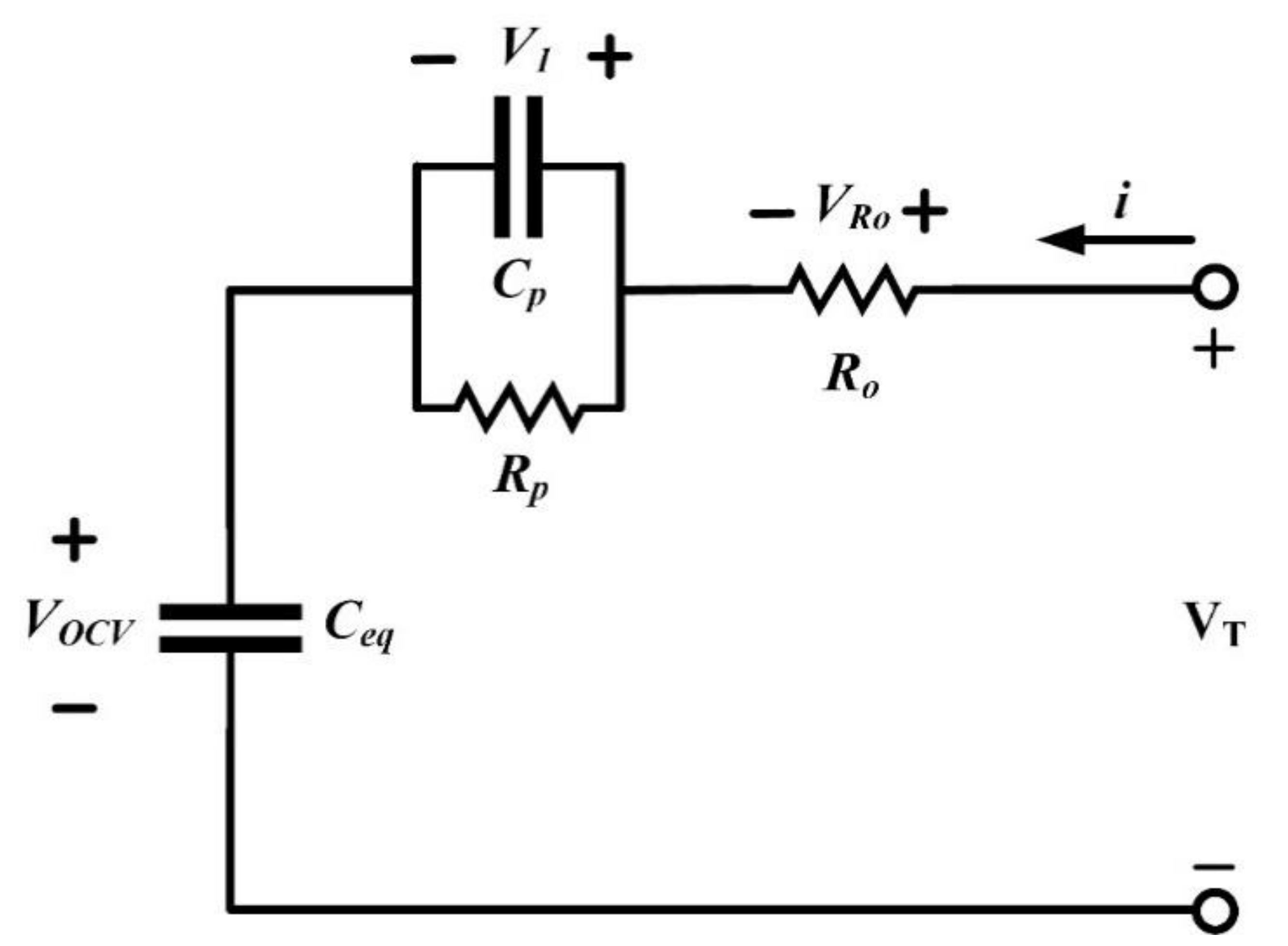
2.1. Battery Modeling

The commonly used battery models can be divided into equivalent circuit models and electrochemical models; the equivalent circuit model is composed of resistances, capacitors, and inductances with the advantages of simplicity and high computing efficiency; the electrochemical model uses the partial differential equation to establish the models of the electrolytic solution and two electrodes models with a view to analyzing the more complicated internal parameters, which require more precision in the models. In order to simplify the complexity of MPC so that it can be realized by a low-cost MCU, this study adopts the equivalent circuit model. As Figure 1 illustrates, the Thevenin equivalent circuit model utilized in this paper is comprised of a battery equivalent capacitor (Ceq), shunt equivalent resistance (Rp), shunt equivalent capacitor (Cp), and series equivalent resistance (Ro). Aiming to combine the battery equivalent model into the model predictive control, Vocv was selected as the output state variable; the charging current i was selected as the input state variable. According to Kirchhoff’s law, V1 can be expressed as Equation (1); Ts represents the sampling time [23,31,32,33,34].
V 1 ( k + 1 ) = a 1 × V 1 ( k ) + b 1 × i ( k ) a 1 = e T s / ( R p × C p ) b 1 = R p × ( 1 e T s / ( R p × C p ) )
In order to indicate the capacitors’ voltage change in batteries, Vocv can be written as Equation (2).
V O C V ( k + 1 ) = V O C V ( k ) + 1 C e q × i ( k ) × T s

2.2. State-Space Representation of Li-Ion Battery Equivalent Circuit Model

The MPC is mainly realized based on plants’ mathematical models [35]. With the aim of allowing the mathematical models to be applied in the control systems, the equivalent circuit models were devised as state-space models. Equations (3) and (4) show the generalized state-space equation; u is the input variable; y stands for the process output; Xm represents the state variable vector with dimension n; Am is the state matrix; Bm is the input matrix; Cm is the output matrix; Dm is the feed-forward matrix.
x m ( k + 1 ) = A m x m ( k ) + B m u ( k )
y ( k ) = C m x m ( k ) + D m u ( k )
Equations (1)–(4) can be discretized into a discrete state-space form, as Equations (5) and (6) demonstrate.
V 1 ( k + 1 ) V O C V ( k + 1 )   V O C V ( k + 1 ) x ( k + 1 ) = a 1 0 0 0 1 0 0 1 1 A V 1 ( k ) V O C V ( k )   V O C V ( k ) x ( k ) + b 1 T s × 1 / C e q T s × 1 / C e q B i ( k )
V O C V ( k ) y ( k ) = 0 0 1 C V 1 ( k ) V O C V ( k )   V O C V ( k ) x ( k )

2.3. Cost Function of the Proposed MPC

The reference value and cost function are defined as Equations (7) and (8), respectively. The first item in the cost function represents the deviation between the reference value and the predicted output; the ΔU in the second item is used to limit the rate of change in the input U; Rs is the diagonal matrix, Rs = rw × INc × Nc (rw > 0), and rw is the weight; when the weight is smaller, a higher rate of change ΔU is allowed.
R s T = 1 1 1 N P r ( k i )
J = ( R s Y ) T ( R s Y ) + Δ U T R _ Δ U

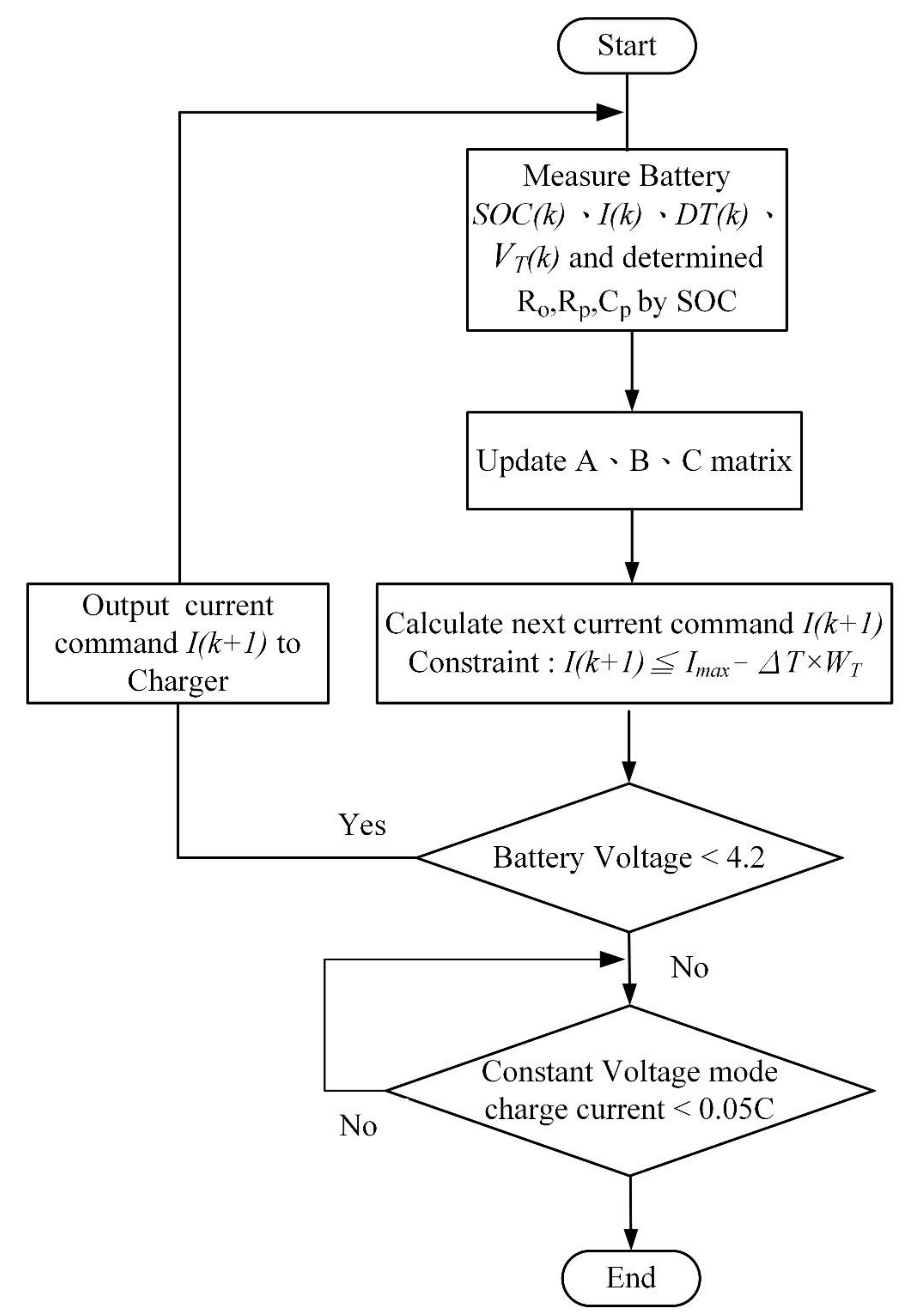
2.4. Derivation of the Proposed MPC Charging Algorithm

According to Section 2.1, it is notable that MPC can predict the future states with the state-space equation and current information. Subsequently, to obtain the optimal predicted input, the following will introduce how to find the optimal solution through the optimizer.
First of all, assuming the sampling time is ki, and ki > 0, the state variable x(ki) can be obtained by measuring the plants’ current information; the definition of the input parameter is shown in Equation (9), and Nc represents the control length.
i ( k i ) , i ( k i + 1 ) , , i ( k i + N C 1 )
With the current x(ki) information, the state variable of Np sampling time can be predicted; Np is the prediction length; the predicted state variable of the plant is shown in Equation (10). x(ki + m|ki) stands for the prediction of the state variables of m steps in the future at the sampling time of ki; the control length should be lesser than the predicted length, Np.
x ( k i + 1 k i ) , x ( k i + 2 k i ) , , x ( k i + m k i ) , , x ( k i + N P k i )
The predicted state variable can be calculated through the predicted input parameter, as Equation (11) presents.
x ( k i + 1 k i ) = A x ( k i ) + B i ( k i ) x ( k i + 2 k i ) = A x ( k i + 1 k i ) + B i ( k i + 1 )   = A 2 x ( k i ) + A B i ( k i ) + B i ( k i + 1 )       x ( k i + N P k i ) = A N P x ( k i ) + A N P 1 B u ( k i ) + A N P 2 B u ( k i + 1 )     + + A N P N C B u ( k i + N C 1 )
The predicted output variable in Equation (12) can be calculated through the predicted state variable in Equation (9).
y ( k i + 1 k i ) = C A x ( k i ) + C B i ( k i ) y ( k i + 2 k i ) = C A 2 x ( k i ) + C A B i ( k i ) + C B i ( k i + 1 ) y ( k i + 3 k i ) = C A 3 x ( k i ) + C A 2 B i ( k i ) + C A B i ( k i + 1 )     + C B i ( k i + 2 )       y ( k i + N P k i ) = C A N P x ( k i ) + C A N P 1 B i ( k i ) + C A N P 2 B i ( k i + 1 )     + + C A N P N C B i ( k i + N C 1 )
A new output and input vector were defined, as demonstrated in Equation (13) and Equation (14). In terms of the single-input single-output (SISO) system, the dimensions of vector Y and ΔU are Np and Nc, respectively; Equations (11)–(14) were merged into Equation (15).
Y = [ y ( k i + 1 k i ) y ( k i + 2 k i ) y ( k i + 3 k i ) y ( k i + N P k i ) ] T
Δ I = [ i ( k i ) i ( k i + 1 ) i ( k i + 2 ) i ( k i + N C 1 ) ] T
Y = F x ( k i ) + ϕ Δ I F = C A C A 2 C A 3 C A N P ; ϕ = C B 0 0 0 C A B C B 0 0 C A 2 B C A B C B 0 C A N P 1 B C A N P 2 B C A N P 3 B C A N P N C B
For the purpose of calculating the ΔI that can minimize the cost function, Equation (15) can be substituted into Equation (8) to obtain Equation (16); then, Equation (16) can be partially differentiated with respect to ΔI, as in Equation (17). The minimum value of the cost function occurs when Equation (17) is equal to zero; therefore, the optimal predicted value ΔI can be obtained as Equation (18). Lastly, the obtained ΔU from Equation (18) can be utilized to calculate the next state’s input, as Equation (19) presents.
J = ( R s F x ( k i ) ) T ( R s F x ( k i ) ) 2 Δ I T ϕ T ( R s F x ( k i ) ) + Δ I T ( ϕ T ϕ + R _ ) Δ I
J Δ I = 2 ϕ T ( R s F x ( k i ) ) + 2 ( ϕ T ϕ + R _ ) Δ I
Δ I = ( ϕ T ϕ + R _ ) 1 ϕ T ( R s F x ( k i ) )
I ( k + 1 ) = I ( k ) + Δ I

2.5. Constraints

0 i ( k + 1 ) i max Δ T * W T
As a means to reduce the charging temperature rise, the constraints shown in Equation (20) were added into the model predictive control. By having this restriction, the proposed algorithm can change the upper limit of the charging current according to the temperature rises during the charging process, which allows the temperature rise to be improved. In this equation, ΔT is the temperature rise and WT is the weight of the temperature rise.

3. Realization of the Proposed MPC Charger

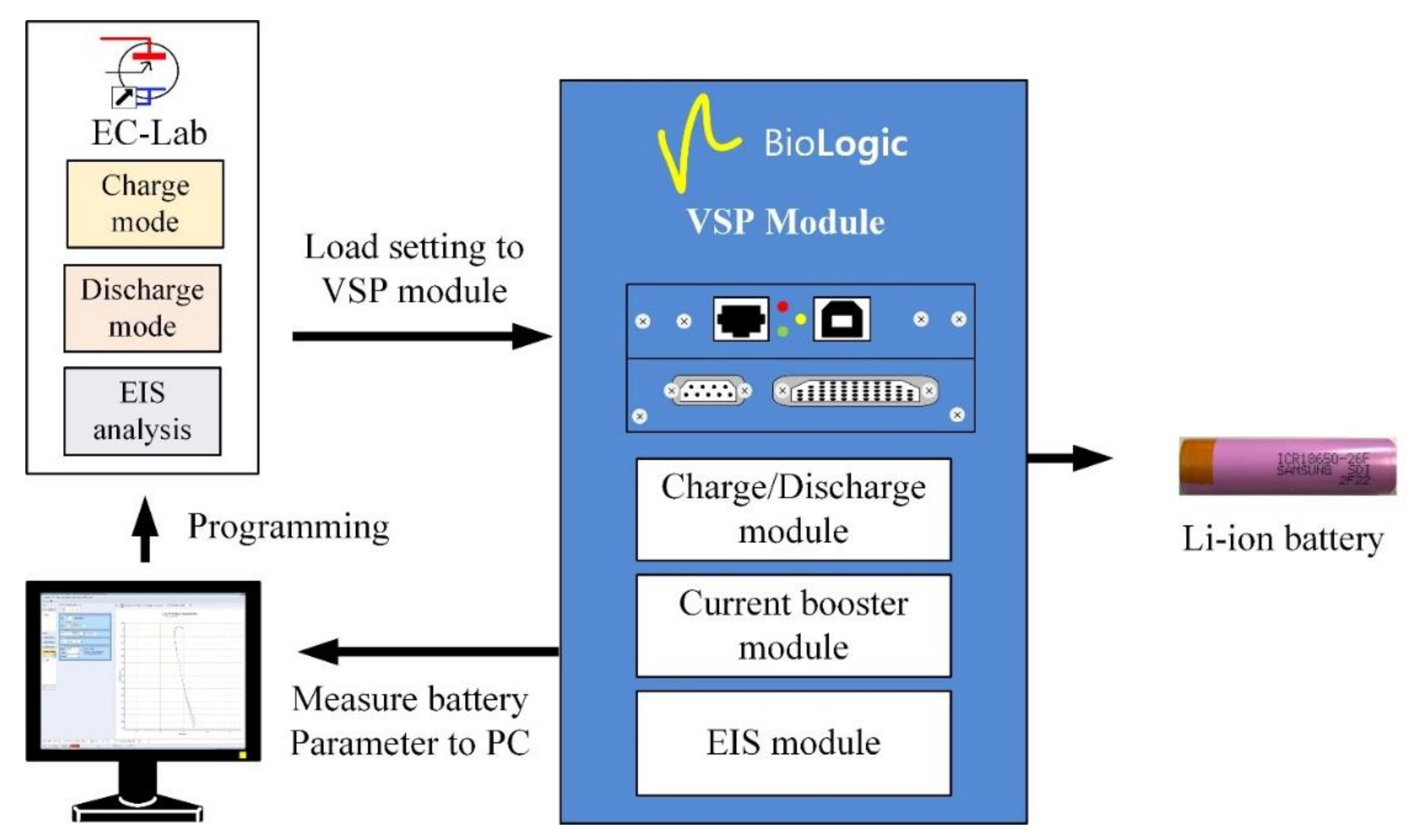
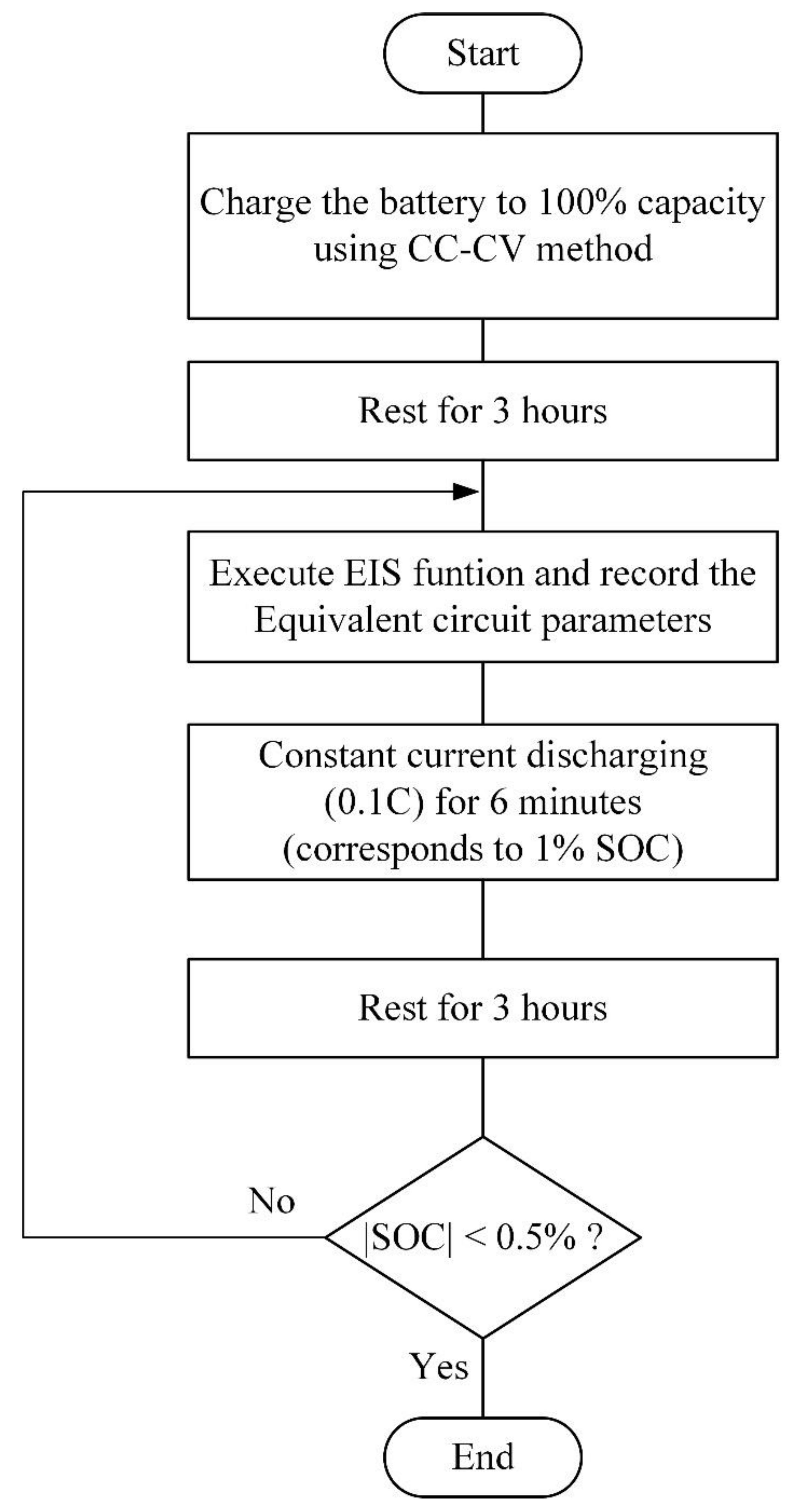
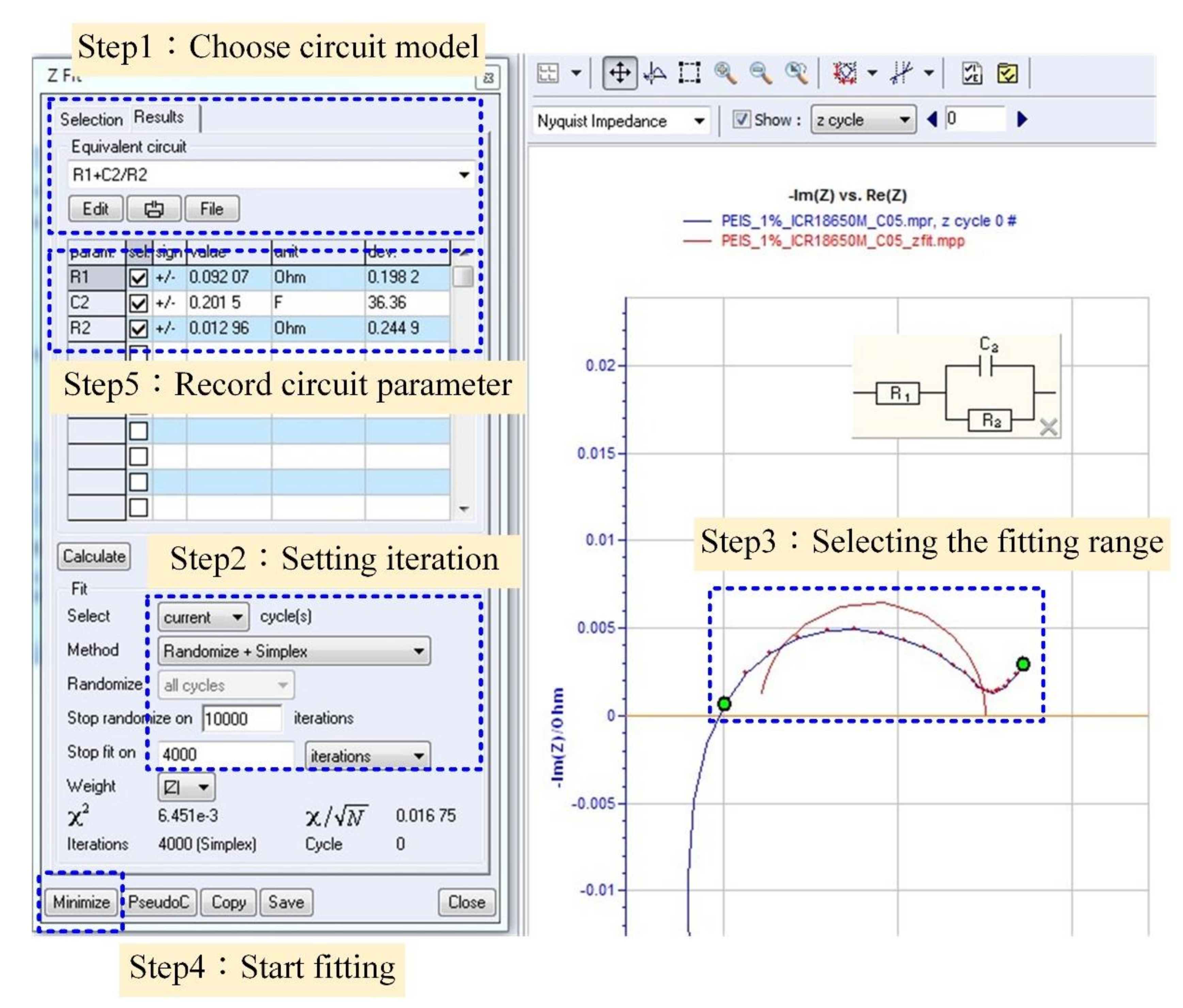
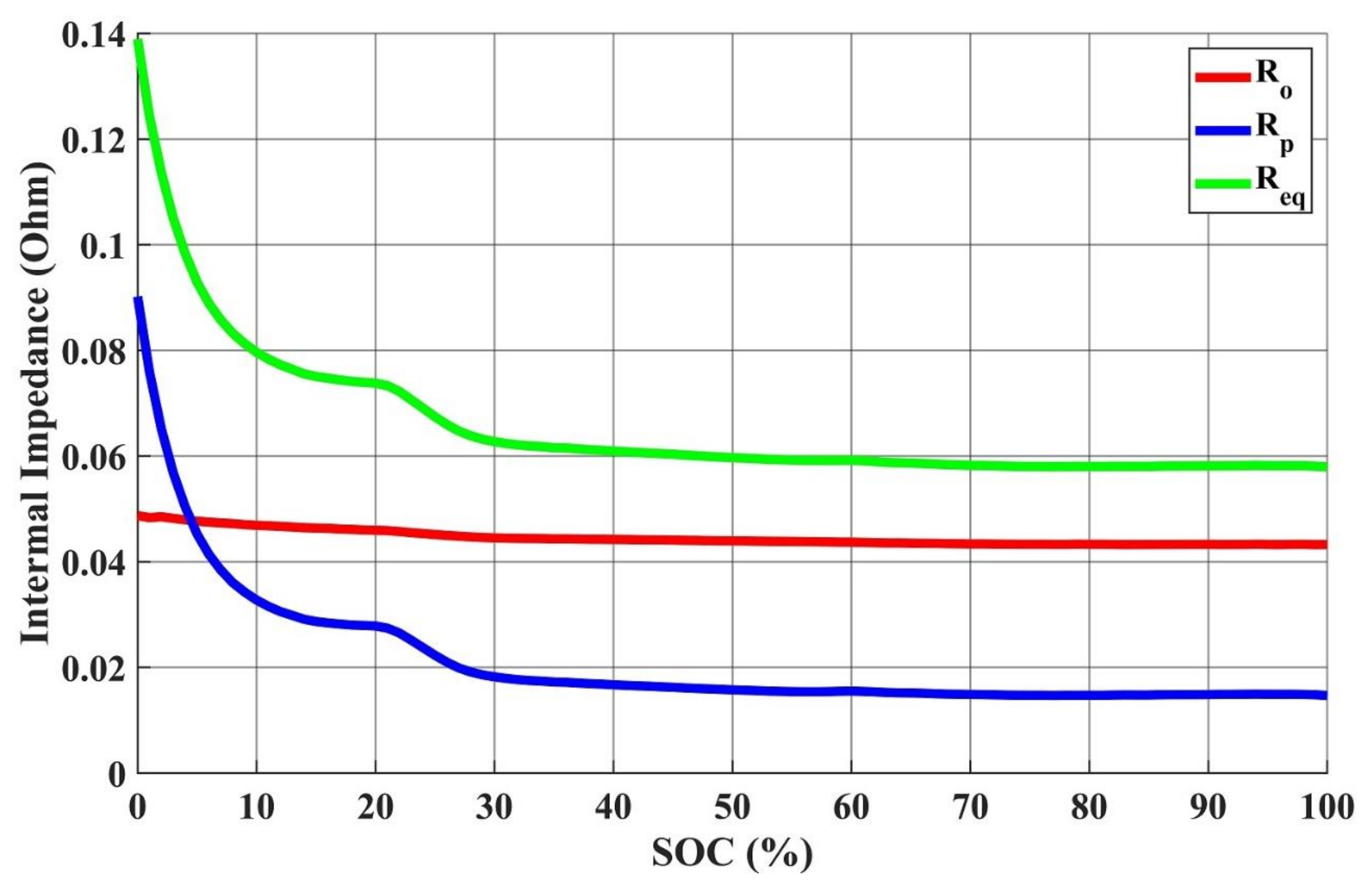
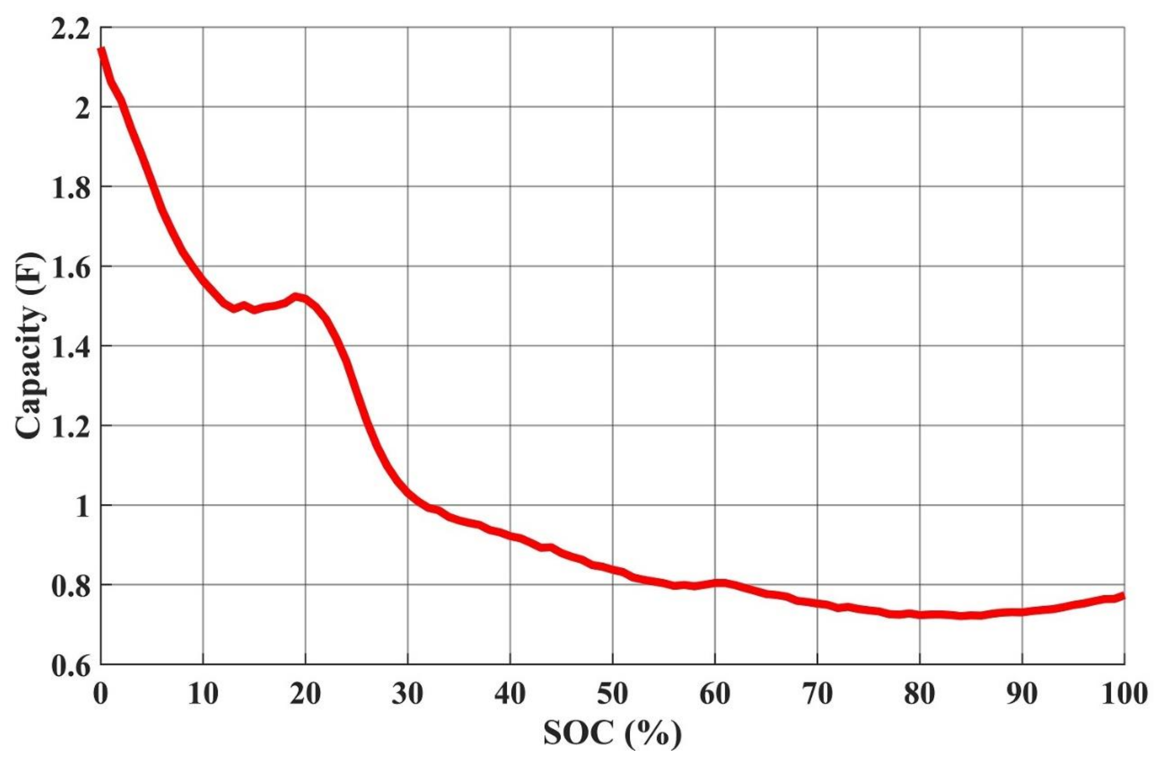
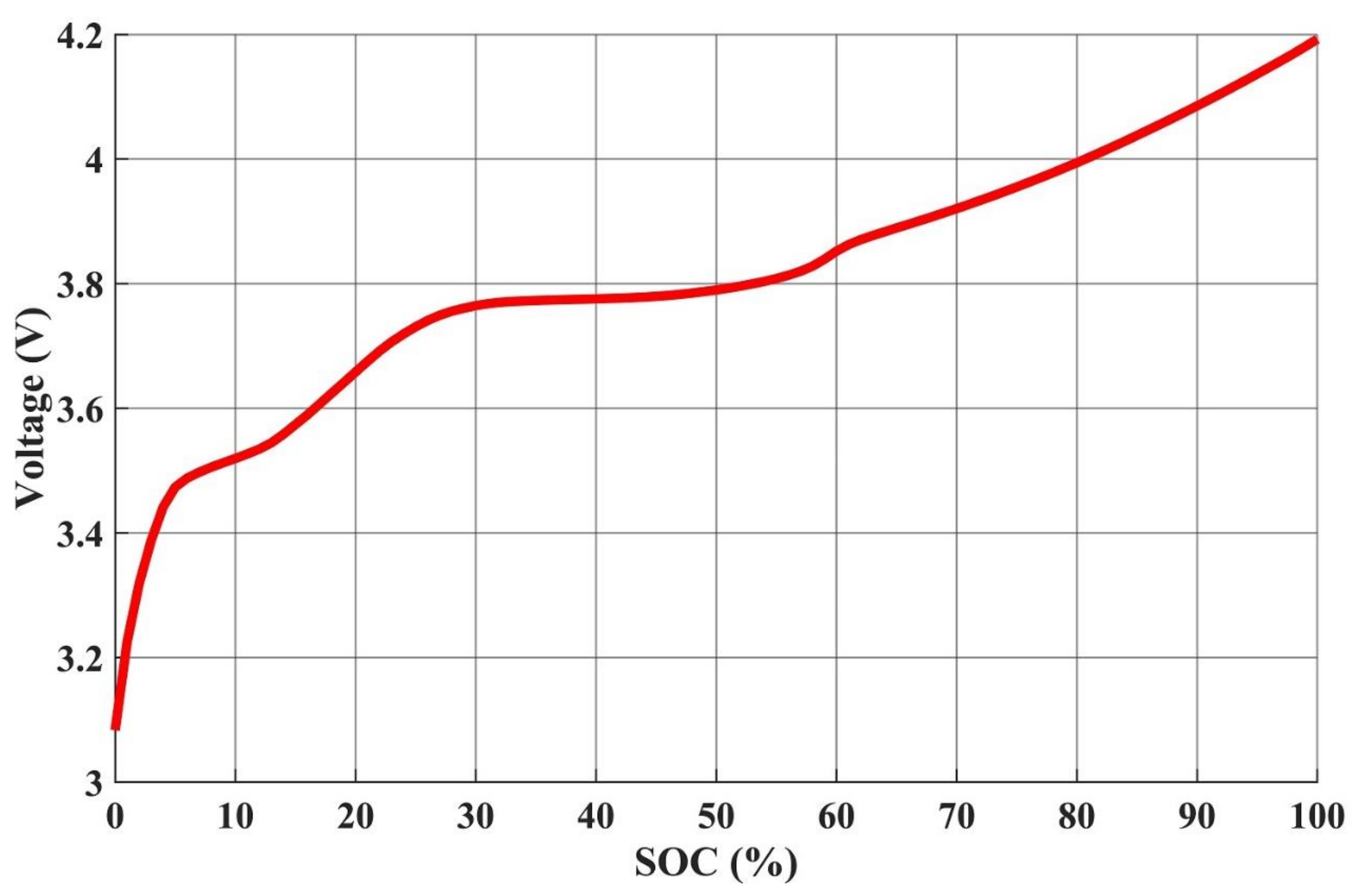
3.1. Identification of Parameters of the Utilized Li-Ion Battery

This study utilized AC Impedance analysis (ACZ) to obtain the internal parameter values of the equivalent circuit models. ACZ uses small amplitude AC sinusoid waveform voltage or current to perturb and analyze the battery chemical reactions under different conditions. In response, the AC impedance values of the battery in different states can be obtained, and curve fitting was conducted on these data to acquire the battery’s circuit parameters.
The test battery selected in this study is the UR18650ZY Li-ion battery launched by SANYO Company, and its specifications are shown in Table 2. In this study, the multifunctional potentiostat VSP-300 from Bio-Logic Corp. was used for ACZ analysis. The block diagram and the flowchart of the ACZ experiments are illustrated in Figure 2 and Figure 3, respectively. In this study, ACZ was measured once every 1% of the SOC. After the measurement, the Nyquist impedance diagrams of different SOCs could be obtained; then, the Z-Fit impedance fitting tool function in EC-Lab was utilized to perform parameter fitting. An illustration of the Z-Fit parameter fitting tool is shown in Figure 4. As Figure 4 illustrates, this study selected the Thevenin equivalent circuit model composed of two resistances and one capacitor to perform parameter fitting. The Z-Fit tool used the selected optimization method to perform curve fitting for the selected measurement points by selecting the curve range to be fitted. The fitting method chosen in this study is the randomized Simplex method and the maximum number of iterations was set to 4000. Figure 5, Figure 6 and Figure 7 show the fitted results obtained by Z-fit tool; afterward, polynomial equations were utilized to conduct curve fitting on the acquired data of open-circuit voltage (OCV), Ro, Rp, and Cp. The fitted results of OCV, Ro, Rp, and Cp are shown in Equations (21)–(24), and the related equation coefficients are listed in Table 3.
S O C = a × V o c 4 + b × V o c 3 + c × V o c 2 + d × V o c + e
R O = a × S O C 4 + b × S O C 3 + c × S O C 2 + d × S O C + e
R p = a × S O C 4 + b × S O C 3 + c × S O C 2 + d × S O C + e
C P = a × S O C 4 + b × S O C 3 + c × S O C 2 + d × S O C + e

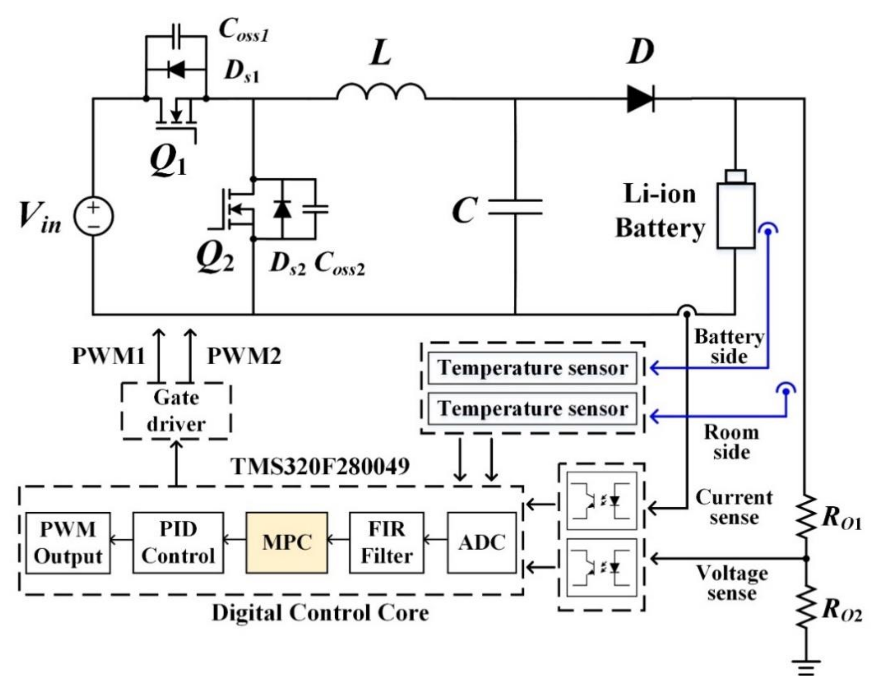
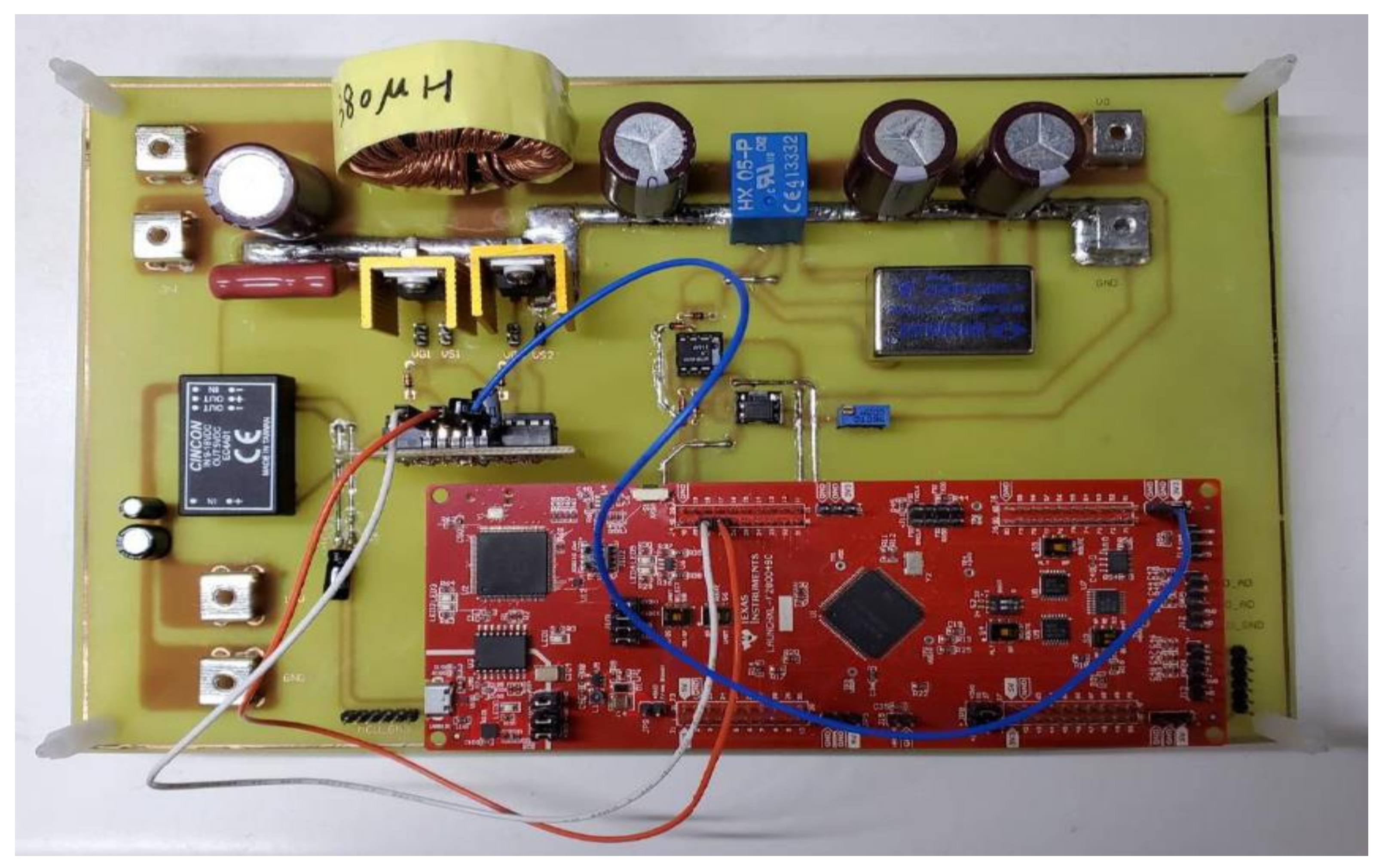
3.2. The Proposed MPC Charger

This study realized a digital battery charger prototyping circuit to conduct the experiments on the 6-series-1-parallel battery set composed of six SANYO UR18650ZY Li-ion batteries; the power stage of the realized charger adopts the synchronous buck converter; its specifications are shown in Table 4. The low-cost TMS320F280049 microcontroller produced by Texas Instruments (TI) was adopted in this paper. All experiments in this study were carried out by placing the battery in an isothermal chamber at 25 °C. Figure 8 displays the block diagram of the proposed MPC charger.
Figure 9 illustrates the flowchart of the realized MPC charging method in this study; the utilized parameters are shown in Table 5. First, the charging current (I), rate of change in temperature (DT), and terminal voltage (VT) are measured; then, the present battery SOC through the Coulomb integral method is obtained. Next, the appropriate series resistance (Ro), shunt capacitor (Cp), and shunt resistance (Rp) based on the current SOC are obtained. With the new series resistance (Ro), shunt capacitor (Cp), and shunt resistance (Rp), the A, B, and C matrixes in Equations (9) and (10) can be updated. Afterward, Equations (22) and (23) are used to calculate the charging current of the next step; then, whether the battery voltage exceeds the upper limit (4.2 V) through the equivalent circuit model is determined. If not, the next step’s charging current should keep being calculating until the battery voltage equals the upper limit voltage; then, the constant voltage mode is changed to charge until the current is less than the battery’s fully charged condition (I < 0.05 C); then, charging stops.

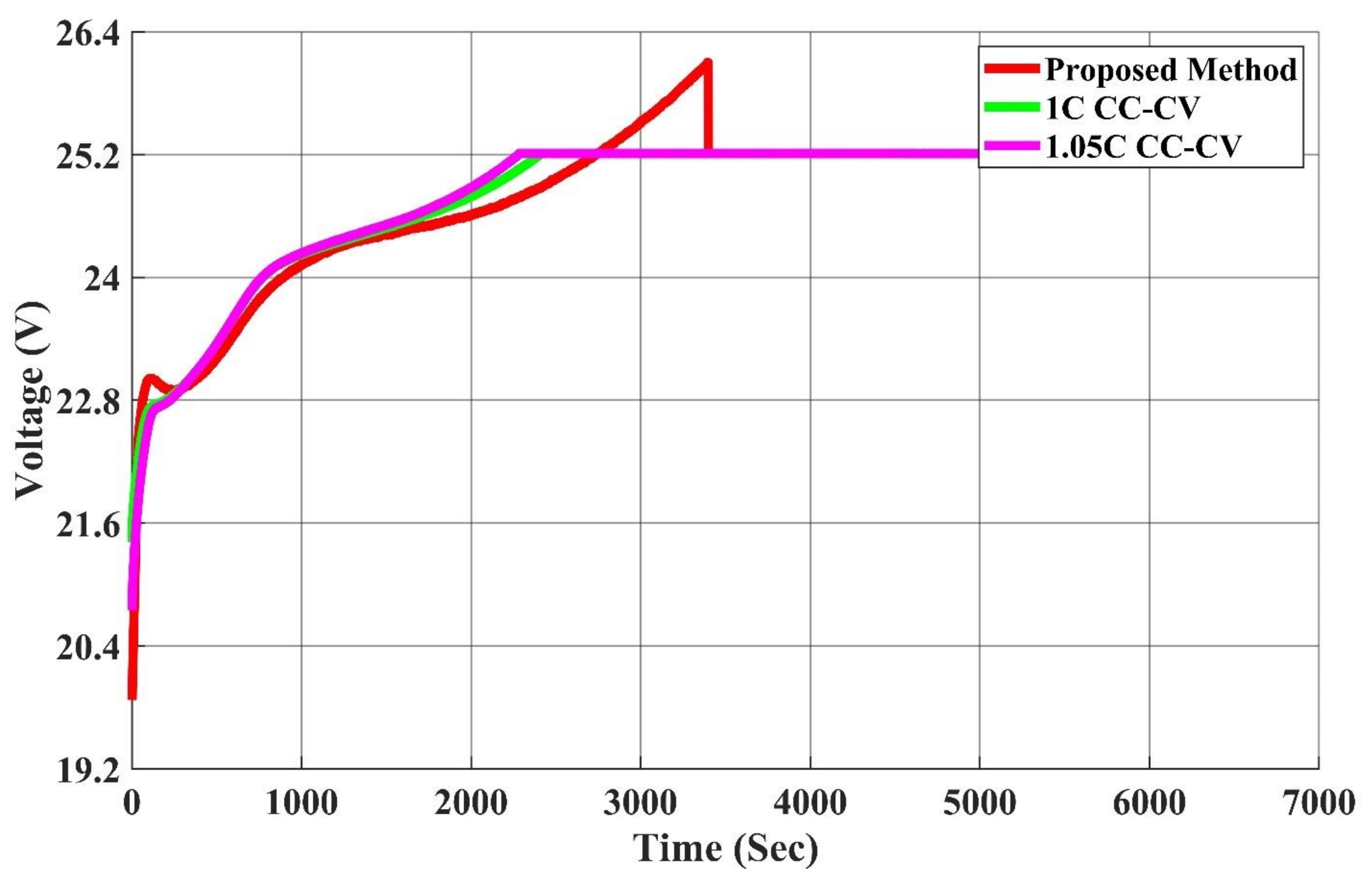
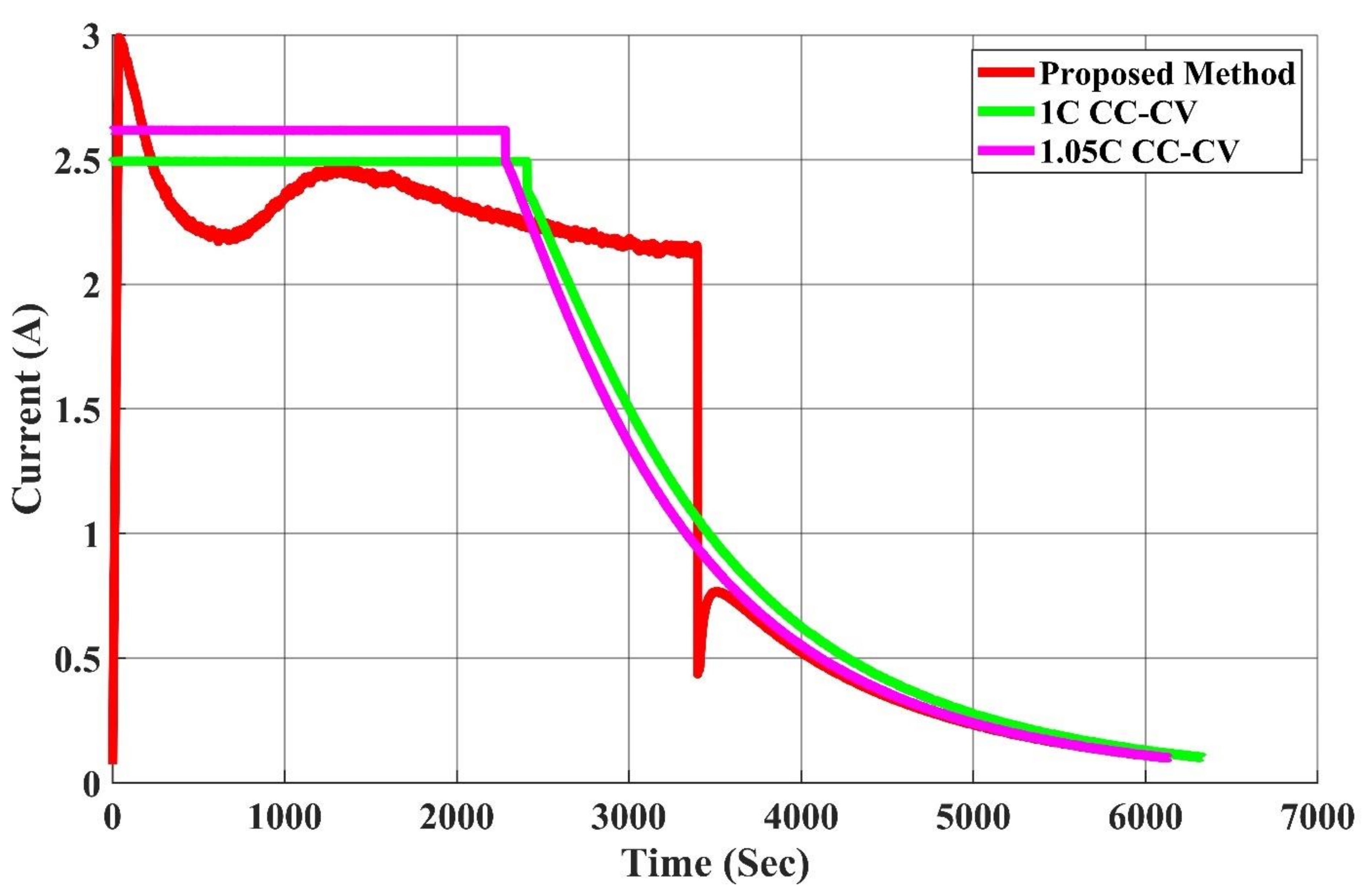
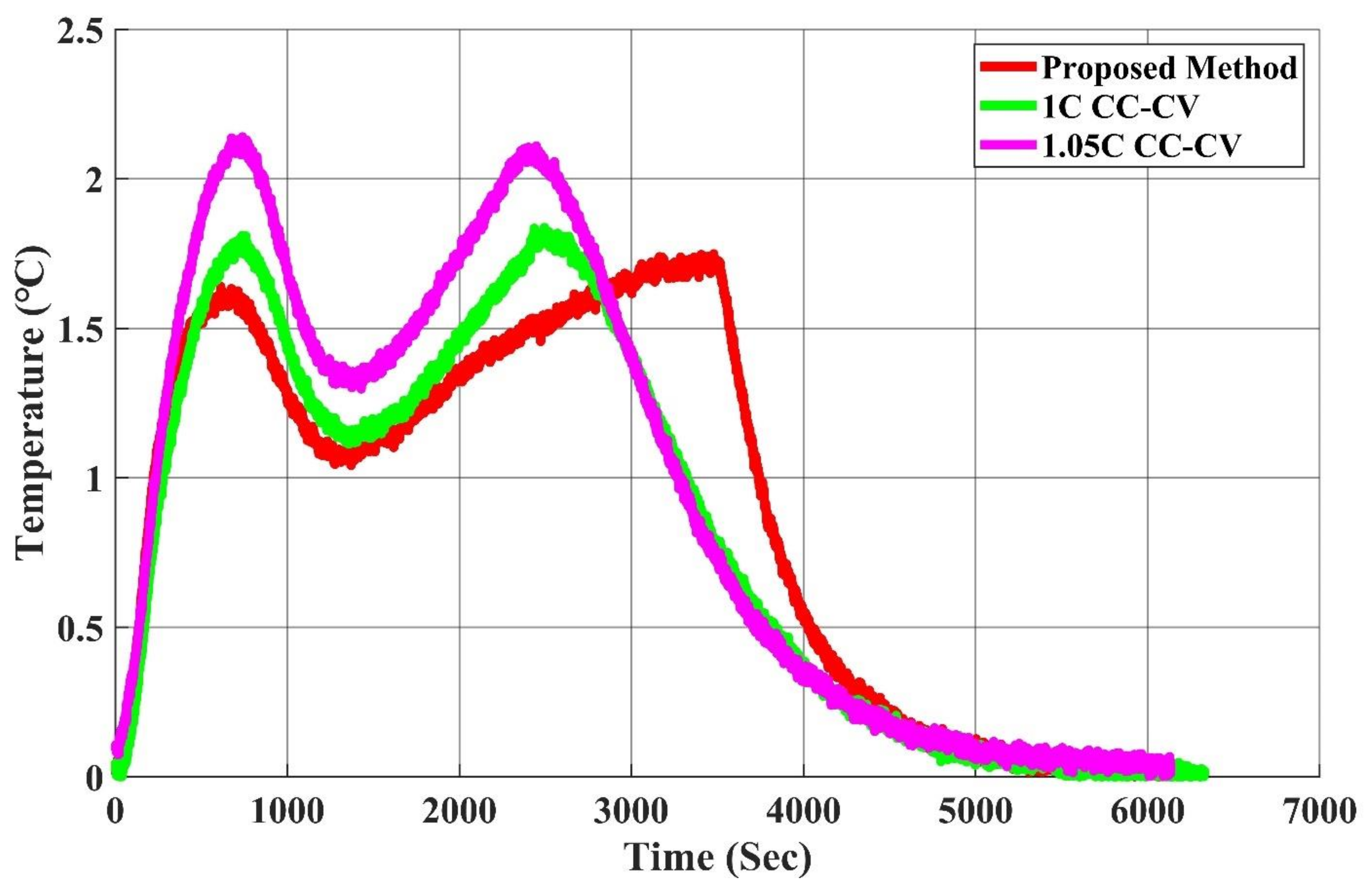
4. Experimental Results

Figure 10 shows the photo of the realized digital MPC charger proposed by this study; this prototyping circuit will then be used to perform the experiments and compare the charging time, charging efficiency, average temperature rise, and the maximum temperature rise of different charging methods. The CV segment in the proposed charging algorithm is the same as the one of the conventional CC-CV charging method; both use a constant voltage (4.2 V) to charge the battery until the battery charging current is less than or equal to the set condition (0.05 C) as the end charging condition. Therefore, this study only compares the temperature rise data in the CC part. The experimental results of the proposed charging method and the different CC-CV charging methods are shown in Table 6; the voltage, current, and the temperature rise waveforms are illustrated in Figure 11, Figure 12 and Figure 13.
From Figure 11, since the charging constraint of the Li-ion battery is that OCV cannot surpass the upper limit voltage (4.2 V), compared with the conventional CC-CV charging method, the proposed charging method adopts the Li-ion battery equivalent circuit model to compute whether the battery OCV exceeds the upper limit voltage in the charging process. Therefore, its CC stage can last for a longer time to accelerate its charging speed.
The experimental results are summarized in Table 7. From Table 7, compared with the 1.0 C CC-CV charging method, the proposed charging method can reduce the average temperature rise and the maximum temperature rise by 0.76% and 3.87%, respectively. It also improves the charging time by 3.25%. The proposed MPC charging technique can attain lower maximum temperature rise and shorter charging time with comparable average temperature rise compared to the 1.0 C CC-CV charging method. In order to further verify the efficacy of the proposed charging method, this study also implemented the 1.05 C CC-CV charging method. As Table 7 shows, compared with the 1.05 C CC-CV charging method, the proposed method improves the charging time, the maximum temperature rise, and the average temperature rise by 0.13%, 18.69%, and 15.03%, respectively. To further validate the effectiveness of the proposed MPC charger, a comparison between the realized scheme and other MPC charging algorithms presented in the literature is provided in Table 8. From Table 8, the proposed MPC charger has the lowest computational complexity as well as the lowest realization cost at the expense of a slightly reduced performance. To sum up, the proposed MPC charging method can obtain a much lower temperature rise and charging time compared with 1.05 C CC-CV charging method. In other words, the proposed method can achieve the goal of reducing the temperature rise at a similar charging speed, thereby achieving the purpose of extending the cycle life of the Li-ion battery.

5. Conclusions

This study devised a model predictive control-based Li-ion battery charging algorithm; the proposed MPC charger calculates the charging current suitable for the current SOC by utilizing the battery equivalent circuit model and model predictive control. Compared with the conventional 1.0 C CC-CV charging method, the charging time, the maximum temperature rise, and the average temperature rise can be improved by 3.25%, 3.87%, and 0.76%. As the experimental results indicate, the charging method proposed by this study can improve the charging temperature rise and charging speed of Li-ion batteries. It should be noted that the proposed method implements only the CC part of the charging algorithm using MPC; the CV stage can also be realized by taking into account the voltage constraints in the optimization problem, which will be considered in future works. The method proposed by this study has advantages as follows:
  • The optimal charging current can be calculated by the model predictive control, thereby achieving the optimal effect.
  • Compared with the conventional CC-CV charging method, the model predictive charging method can effectively improve the charging temperature rise, charging speed, and charging efficiency.
  • In comparison with the MPC method proposed in the literature, the model and constraint used in the proposed method are much more straightforward; thus, it is suitable for being realized by a low-cost MCU.

Author Contributions

G.-J.C., Y.-H.L., Y.-S.C. and H.-Y.P. made considerable contributions in this research; G.-J.C. and Y.-H.L. proposed ideas and research concepts; G.-J.C. completed the battery characteristic experiments, implemented hardware and carried out MCU firmware programming; Y.-S.C. and H.-Y.P. completed the simulation platform and experimental platform during the research process. All authors are responsible for the integrity of the work as a whole. All authors have read and agreed to the published version of the manuscript.

Funding

This research received no external funding.

Institutional Review Board Statement

Not applicable.

Informed Consent Statement

Not applicable.

Data Availability Statement

The data presented in this study are available on request from the corresponding author.

Conflicts of Interest

The authors declare no conflict of interest.

References

  1. Guan-Chyun, H.; Liang-Rui, C. Fuzzy controlled Lithium-Ion Battery Charge System with Active State of Charge Controller. Trans. Ind. Electron. 2001, 48, 585–593. [Google Scholar] [CrossRef]
  2. Tsang, K.M.; Chan, W.L. Current sensorless quick charger for lithiumion batteries. Energy Convers. Manag. 2011, 52, 1593–1595. [Google Scholar] [CrossRef]
  3. Chen, L.-R. PLL-Based Battery Charge Circuit Topology. IEEE Trans. Ind. Electron. 2004, 51, 1344–1346. [Google Scholar] [CrossRef]
  4. Chen, L.-R.; Chen, J.-J.; Chu, N.-Y.; Han, G.-Y. Current-Pumped Battery Charger. IEEE Trans. Ind. Electron. 2008, 55, 2482–2488. [Google Scholar] [CrossRef]
  5. Wang, S.-C.; Chen, G.-J.; Liu, Y.-H. Adaptive Charging Strategy With Temperature Rise Mitigation and Cycle Life Extension for Li-ion Batteries. CPSS Trans. Power Electron. Appl. 2018, 3, 202–212. [Google Scholar] [CrossRef]
  6. Chen, L.-R. A Design of an Optimal Battery Pulse Charge System by Frequency-Varied Technique. IEEE Trans. Ind. Electron. 2007, 54, 398–405. [Google Scholar] [CrossRef]
  7. Liang-Rui, C. A design of duty-varied voltage pulse charger for improving lithium-ion battery-charging response. Trans. Ind. Electron. 2009, 56, 480–487. [Google Scholar] [CrossRef]
  8. De Jongh, P.E.; Notten, P.H.L. Effect of current pulses on lithium intercalation batteries. Solid State Ion. 2002, 148, 259–268. [Google Scholar] [CrossRef]
  9. Li, J.; Murphy, E.; Winnick, J.; Kohl, P.A. The effects of pulse charging on cycling characteristics of commercial lithium-ion batteries. J. Power Sources 2001, 102, 302–309. [Google Scholar] [CrossRef]
  10. Isuru, N.S.M.; Siriroj, S. An Adaptive Pulse Charging Algorithm for Lithium Batteries. In Proceedings of the 14th International Conference on Electrical Engineering/Electronics, Computer, Telecommunications and Information Technology (EC-TI-CON), Phuket, Thailand, 27–30 June 2017; pp. 218–221. [Google Scholar]
  11. Huazhen, F.; Christopher, D.; Vadim, L. Optimal pulse-modulated Lithium-ion battery charging Algorithms. J. Energy Storage 2018, 15, 359–367. [Google Scholar]
  12. Yi-Hwa, L.; Ching-Hsing, H.; Yi-Feng, L. Search for an optimal rapid charging pattern for Li-ion batteries using consecutive orthogonal arrays. IEEE Trans. Energy Convers. 2011, 26, 654–661. [Google Scholar]
  13. Thanh, T.V.; Xiaopeng, C.; Weixiang, S.; Ajay, K.; Joe-Air, J. New charging strategy for lithium-ion bat-teries based on the integration of taguchi method and state of charge estimation. J. Power Sources 2015, 273, 413–422. [Google Scholar]
  14. Liu, Y.-H.; Luo, Y.-F. Search for an optimal rapid-charging pattern for li-ion batteries using the taguchi approach. IEEE Trans. Ind. Electron. 2010, 57, 3963–3971. [Google Scholar] [CrossRef]
  15. Wang, S.-C.; Liu, Y.-H. A PSO-Based Fuzzy-controlled searching for the optimal charge pattern of li-ion batteries. IEEE Trans. Ind. Electron. 2015, 62, 2983–2993. [Google Scholar] [CrossRef]
  16. Yi-Hwa, L.; Jen-Hao, T.; Yu-Chung, L. Search for an optimal rapid charging pattern for Li-ion batteries using ant colony system algorithm. IEEE Trans. Ind. Electron. 2005, 52, 1328–1336. [Google Scholar]
  17. Lee, C.-H.; Chen, M.-Y.; Hsu, S.-H.; Jiang, J.-A. Implementation of an SOC-based four-stage constant current charger for Li-ion batteries. J. Energy Storage 2018, 18, 528–537. [Google Scholar] [CrossRef]
  18. Lee, C.-H.; Chang, T.-W.; Hsu, S.-H.; Jiang, J.-A. Taguchi-based PSO for searching an optimal four-stage charge pattern of Li-ion batteries. J. Energy Storage 2019, 21, 301–309. [Google Scholar] [CrossRef]
  19. Khan, A.B.; Choi, W. Optimal Charge Pattern for the High-Performance Multistage Constant Current Charge Method for the Li-Ion Batteries. IEEE Trans. Energy Convers. 2018, 33, 1132–1140. [Google Scholar] [CrossRef]
  20. Hosseinzadeh, M.; Cotorruelo, A.; Limon, D.; Garone, E. Constrained Control of Linear Systems Subject to Combinations of Intersections and Unions of Concave Constraints. IEEE Control. Syst. Lett. 2019, 3, 571–576. [Google Scholar] [CrossRef]
  21. Dan, H.; Yamauchi, J.; Hatanaka, T.; Fujita, M. Control Barrier Function-Based Persistent Coverage with Performance Guarantee and Application to Object Search Scenario. 2020 IEEE Conf. Control. Technol. Appl. (Ccta) 2020, 640–647. [Google Scholar] [CrossRef]
  22. Yan, J.; Xu, G.; Qian, H.; Xu, Y.; Song, Z. Model predictive control-based fast charging for vehicular batteries. Energies 2011, 4, 1178–1196. [Google Scholar] [CrossRef] [Green Version]
  23. Xavier, M.A.; Trimboli, M.S. Lithium-ion battery cell-level control using constrained model predictive control and equivalent circuit models. J. Power Sources 2015, 285, 374–384. [Google Scholar] [CrossRef] [Green Version]
  24. Torchio, M.; Magni, L.; Braatz, R.; Raimondo, D. Optimal Health-aware Charging Protocol for Lithium-ion Batteries: A Fast Model Predictive Control Approach. IFAC-Pap. 2016, 49, 827–832. [Google Scholar] [CrossRef]
  25. Kujundžić, G.; Ileš, Š.; Matuško, J.; Vašak, M. Optimal charging of valve-regulated lead-acid batteries based on model predictive control. Appl. Energy 2017, 187, 189–202. [Google Scholar] [CrossRef]
  26. Goran, K.; Šandor, I.; Jadranko, M.; Mario, V. Electrothermal dynamics-conscious lithium-ion battery cell-level charging management via state-monitored predictive control. Energy 2017, 141, 250–259. [Google Scholar]
  27. Zou, C.; Manzie, C.; Nesic, D. Model predictive control for lithium-ion battery optimal charging. IEEE/ASME Trans. Mechatron. 2018, 23, 947–957. [Google Scholar] [CrossRef]
  28. Resmi, S.; Raghunathan, R. Modeling and contorl of battery systems. PartII: A model predictive controller for optimal charging. Comput. Chem. Eng. 2018, 119, 326–335. [Google Scholar]
  29. Pozzi, A.; Torchio, M.; Braatz, R.D.; Raimondo, D.M. Optimal charging of an electric vehicle battery pack: A real-time sensitivity-based model predictive control approach. J. Power Sources 2020, 461, 228133. [Google Scholar] [CrossRef]
  30. Yin, Y.; Choe, S.-Y. Actively temperature controlled health-aware fast charging method for lithium-ion battery using nonlinear model predictive control. Appl. Energy 2020, 271, 115232. [Google Scholar] [CrossRef]
  31. Bor, Y.L.; Ganesan, N.; Rudolph, G.J.; Daniel, H.D. Modeling of lithium ion cells—A simple equivalent-circuit model approach. Solid State Ionics 2004, 175, 835–839. [Google Scholar]
  32. Dubarry, M.; Vuillaume, N.; Liaw, B.Y. From single cell model to battery pack simulation for Li-ion batteries. J. Power Sources 2009, 186, 500–507. [Google Scholar] [CrossRef]
  33. Chiang, Y.-H.; Sean, W.-Y.; Ke, J.-C. Online estimation of internal resistance and open-circuit voltage of lithium-ion batteries in electric vehicles. J. Power Sources 2011, 196, 3921–3932. [Google Scholar] [CrossRef]
  34. Hu, X.; Li, S.; Peng, H. A comparative study of equivalent circuit models for Li-ion batteries. J. Power Sources 2012, 198, 359–367. [Google Scholar] [CrossRef]
  35. Liuping, W. Model Predictive Control System Design and Implementation Using MATLAB®; Springer: Berlin, Germany, 2009. [Google Scholar]
  36. Sanyo. UR18650ZY Datasheet. Available online: https://www.rowa.co.jp/data/img/UR18650ZY.pdf (accessed on 19 March 2021).
Figure 1. The utilized Thevenin equivalent circuit model.
Energies 14 02238 g001
Figure 2. Block diagram of the AC Impedance analysis (ACZ) experiments.
Energies 14 02238 g002
Figure 3. Flowchart of the ACZ experiments.
Energies 14 02238 g003
Figure 4. Illustration of the Z-Fit parameter fitting tool.
Energies 14 02238 g004
Figure 5. Relationship between series equivalent resistance (Ro), shunt equivalent resistance (Rp) and equivalent resistance (Req) and state of charge (SOC).
Energies 14 02238 g005
Figure 6. Relationship between shunt equivalent capacitor (Cp) and SOC.
Energies 14 02238 g006
Figure 7. Relationship between open circuit voltage (Vocv) and state-of charge (SOC).
Energies 14 02238 g007
Figure 8. Block diagram of the proposed model predictive control (MPC) charger.
Energies 14 02238 g008
Figure 9. Flowchart of the proposed MPC charging algorithm.
Energies 14 02238 g009
Figure 10. Picture of the proposed MPC charger.
Energies 14 02238 g010
Figure 11. Comparison of the charging voltages of different charging methods.
Energies 14 02238 g011
Figure 12. Comparison of the charging currents of different charging methods.
Energies 14 02238 g012
Figure 13. Comparison of the temperature rise waveforms of different charging methods.
Energies 14 02238 g013
Table 1. Comparison of model predictive control (MPC) charging methods proposed in the literature.
Ref.Utilized ModelOptimization MethodRealization PlatformExperimentally Validated?
[22]ECM and thermal model based on neural networkGenetic algorithmPCYes
[23]ECM (1RC model)Solve pseudo minimum-time problemPCNo
[24]Linearized P2D modelSolve quadratic programPC/MATLABNo
[25]Hybrid electrical (2RC) and temperature modelSolve quadratically constrained quadratic programPC/MATLABYes
[26]Electrical-thermal model and AEKF for SOC estimationMinimize the difference between SOC and optimal SOC trajectoryPC/MATLABNo
[27]Reduced-order PDE modelMinimize the difference between SOC/SOH and optimal SOC/SOH trajectoryPC/MATLABNo
[28]Simple lumped PDE modelSolve quadratic programPC/MATLABNo
[29]Single-particle model (PDE)Solve sensitivity-based MPC quadratic programPC/MATLABNo
[30]Reduced-order electrochemical life modelTwo offline optimizations and one online optimizationPC/MATLABNo
Table 2. UR18650ZY specification table [36].
SANYO UR18650ZY Lithium-Ion Battery
Rated Capacity2600 mAh
Minimum Rated Capacity2500 mAh
Rated Voltage3.7 V
Cutoff Voltage3 V
Specification18.4 mm—diameter, 65 mm—height
Standard Charging ConditionCC-CV, 1250 mA, 4.2 V
Weight43.5 g
Charging Temperature0~40 °C
Discharging Temperature−20~60 °C
Table 3. The obtained curve fitting coefficients.
abcde
OCV−482.56886−3.659 × 1048.592 × 104−7.526 × 10⁴
RO9.695 × 10−11−2.908 × 10−83.528 × 10−6−0.00021390.04876
RP5.61 × 10−9−1.35 × 10−60.0001153−0.0041630.07031
CP−1.988 × 10⁻⁹−1.392 × 10−60.0004701−0.044172.056
Table 4. Specification of the utilized synchronous buck converter.
Input voltage (Vin)72 V
Output voltage (Vout)25.2 V
Output power (Pout)100 W
Efficiency (η)>90%
Switching frequency (fs)100k Hz
Output voltage ripple (ΔVo/Vo)<1%
Output current ripple (ΔIo/Io)<10%
Table 5. Parameters of the implemented MPC.
TsNPNCrwWTImax
1 s10410.53 A
Table 6. Experimental results of different charging methods.
MPC1 C
CC-CV
1.05 C
CC-CV
Average Temperature Rise * (°C)1.301.311.53
Maximum Temperature Rise * (°C)1.741.812.14
Charging Time (Sec)612663326134
Efficiency (%)99.6299.6599.59%
* considering only the CC stage.
Table 7. Improvement of the proposed method over different CC-CV methods.
1 C
CC-CV
1.05 C
CC-CV
Average Temperature Rise (%)0.76%15.03%
Maximum Temperature Rise (%)3.87%18.69%
Charging Time (%)3.25%0.13%
Table 8. Comparison of different MPC-based charging techniques.
RefComplexity of MPC SolverModel ComplexityComputation TimeAdditional RequirementHardware RealizationPerformance
proposed methodLowLowFast-YesSuboptimal
[22]MediumMediumMediumGA, NNNoOptimal
[24]LowHighMedium-NoOptimal
[26]HighMediumSlowExtended Kalman FilterNoOptimal
[29]MediumHighSlow-NoOptimal
Publisher’s Note: MDPI stays neutral with regard to jurisdictional claims in published maps and institutional affiliations.

