1. Introduction
CO
2 reduction is the main goal in the modern automotive engine. The strong limits on exhaust emissions imposed by the European Commission (EC) and the United States Environmental Protection Agency (EPA) for passenger cars have prompted the automotive industry to develop technological solutions to improve the global efficiency of the propulsion system to limit fuel consumption and pollutant emissions, without compromising vehicle performance and drivability [
1]. Furthermore, the adoption of advanced liquid and gaseous biofuels will lead to a progressive replacement of fossil fuel with a renewable energy source over the next decades [
2]. The Internal Combustion Engine (ICE) can, therefore, play an important role in a medium-term scenario thanks to the progressive electrification of the powertrain through Hybrid Vehicles [
3] and the development of integrated technologies. Turbocharging (TC) is one of the most commonly used ways to achieve these goals, allowing downsizing without compromising engine power. The adoption of multi-entry coupled with a properly designed exhaust piping arrangement allows for a significant improvement in transient response. Furthermore, the two entries could be fed separately due to their design and, when connected to different cylinders taking into account the firing order, the exhaust process is optimized to avoid backflow.
In twin-entry turbines, the scroll is meridionally divided with a single divider around the entire perimeter of the casing and can operate under different admission conditions:
Full admission when the thermodynamic flow parameters at the inlet of the two sectors have the same value;
Partial admission when the mass flow rate in a sector drops to zero (extreme condition);
Unequal admission when the sectors have different inlet pressure, temperature and mass flow rate.
Twin-entry turbines have a wider use for automotive applications due to their simple design and increased performance under unequal admission conditions.
Pishinger and Wunsche [
4] first measured the steady flow characteristic curves of the twin-entry radial turbine in partial and full admission conditions. The results showed that the loss of efficiency under unequal admission operations depends on the geometry and design of the volute. Dale and Watson [
5] continued the study performed by the Pischinger and Wunsche on the twin-entry turbine in equal and unequal admission. Thanks to valves used to gradually vary the flow rate in each sector, they showed that in full admission conditions, there is an equal division of the overall mass flow rate in the two sectors, while the mass flow rate in one sector increases when the pressure on the other side decreases. Efficiency is affected differently by the two sectors. In fact, the maximum value was obtained when the mass flow rate was greater at the shroud side entry than at the hub entry (not at full admission). Capobianco and Gambarotta studied the performance of the turbocharger Garret T025 equipped with a twin-entry turbine on the test bench of the University of Genova in [
6]. The experimental investigation was extended to both steady and unsteady flow. The steady flow turbine performance was evaluated under full, partial and unequal admission conditions. The two entries appeared significantly different, both in terms of mass flow rate and efficiency map. Full and partial admission investigations highlighted that mass flow rate and efficiency were always larger for outer entry from the central housing (shroud). This different behavior was justified referring to an asymmetry with regard to the meridional dividing plane highlighted by the housing and the rotor geometry. Based on steady flow maps, many turbine models have been introduced over the years. As far as multi-entry turbines are concerned, the exhaust pulses generated by the periodic opening and closing valves of the ICE valves cause unbalanced admission for most of the time. For this, full admission maps in steady state are not sufficient for prediction and simulation purposes as reported by Cerdoun and Ghenaiet [
7]. An aerodynamic characterization of an asymmetrical twin-entry turbine is reported in this paper under engine operating conditions based on RANS simulations. The incidence of the flow at the entry to the rotor is strongly influenced by flow interactions in the volute and in the inter-space.
Serrano et al. [
8] suggested a data analysis protocol which allows the testing procedure of twin entry turbines to be organized with different steady flow admission and in quasi-adiabatic conditions to optimize and develop quasi-steady models. The model of Ghassemi et al. [
9] is based on the modification of the prediction method used for one-dimensional single-entry turbines with the introduction of rotor-mixing losses as well as a different evaluation of friction, clearance and blade loading losses coefficient. A comparison with experimental data shows a good trend matching but with some differences for a high u/c
s ratio and when the mass flow ratio is far from the optimal value. This behavior suggests lower accuracy of rotor mixing losses. A better prediction model is obtained by Hajilouy, Rad and Shahhosseini [
10], with a new procedure for the loss evaluation, which carries an error of 1.5% with respect to the experimental data. Other important studies are performed by Romagnoli et al. [
11] with a map-based method for the prediction of unequal and partial admission behavior of twin-entry and double-entry turbines from full admission maps. A more accurate prediction model is presented by Romagnoli, Martinez-Botas and Xue [
12] by analyzing different admission conditions and a loss mechanism by introducing CFD simulations. The Authors developed a validated CFD model in order to perform an in-depth analysis of the different contribution of losses in the twin entry turbine; the greatest performance is obtained when the rotor is fed from the shroud side thanks to the removal of the tornado vortex. Wei et al. [
13] developed a reduced-order model of a twin entry turbine capable of capturing the influence of flow distortion, due to partial and unbalanced admission, on turbine rotor performance. Cravero et al. [
14] developed a complete CFD model of a twin scroll radial turbine and perform simulations in full and partial admission to contribute to the literature in the understanding of this turbomachinery; moreover, they proposed several performance indices for optimization purposes.
Furthermore, twin-entry turbines can be applied to the Organic Rankine Cycle (ORC) unit adopted for the waste-heat recovery solution from exhaust gases to reduce CO
2 emissions [
15]. Some efforts in the transport sector are required especially in off-design condition of all components of the recovery unit and considering fluctuating conditions. To this end, a twin-entry turbine could be a good solution to achieve this goal.
In this paper, a wide experimental characterization of a twin entry turbine is reported with reference to the turbine performance measured under different admission conditions. The steady flow experimental campaign was developed at the turbocharger test bench of the University of Genoa, in order to highlight the behavior of the twin entry turbine in full, partial and unbalanced admission typically occurring in engine application. The results here reported show a different behavior of each sector and the interactions between the two entries, which must be taken into account to optimize engine-turbocharger matching calculation.
2. Experimental Setup and Measuring Equipment
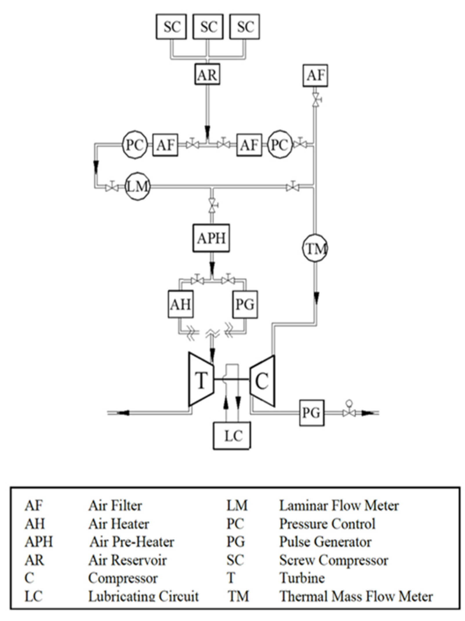
The experimental activity was carried out at the turbocharger test bench of the University of Genoa (
Figure 1) [
16,
17]. Three screw compressors could supply a total mass flow rate of 0.6 kg/s at a maximum pressure of 8 bar. “Cold” and “hot” experimental investigations can be performed through an electric air heating station, which allows turbine inlet air up to 750 °C.
An automatic data acquisition system performs measurements through interactive procedures in the LabVIEW
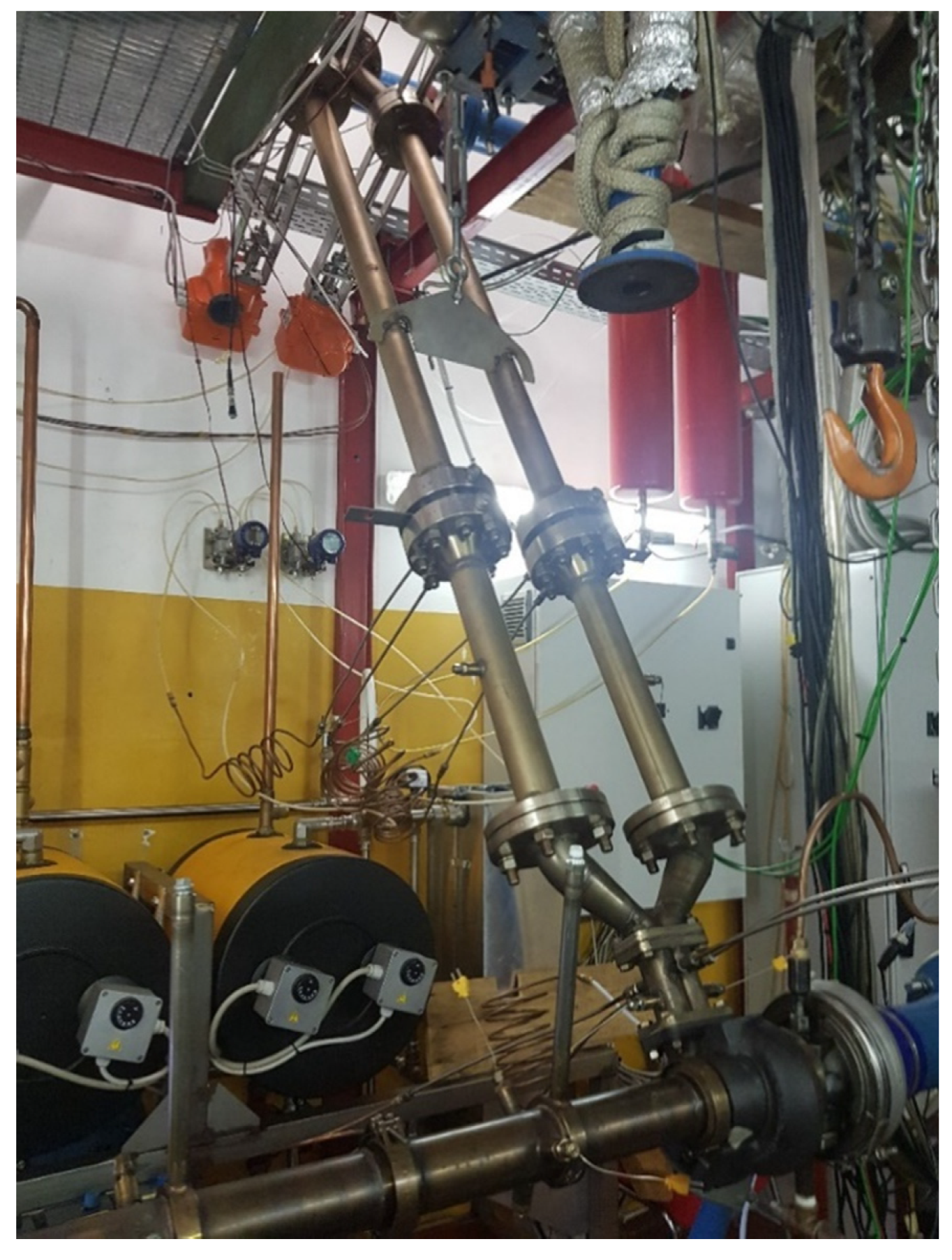
® environment. Several average parameters are measured upstream and downstream of compressor and turbine. Static pressures are measured using strain-gauge and piezoresistive transducers (accuracy of ±0.15% of full scale). Platinum resistance thermometers (with an accuracy of ±0.15 °C ± 0.2% of measured value) and thermocouples are used to record total temperatures. Compressor mass flow rate is measured using a thermal mass flow meter (with an accuracy of ±0.9% measured value and ±0.05% of the full scale). Turbine mass flow rate is measured through a laminar flow meter (with an accuracy of ±2% of the measured value). Turbocharger rotational speed is captured using an eddy current probe (with an accuracy of ±0.009% of the measured value). Two separated ducts provide flow at each turbine sector. After the electrical heater, a Y junction is installed followed by two motorized throttle valves; through a voltage signal, its position can be controlled from the completely closed to the fully open position. Infinite ratios between the flow rate in the two sectors are allowed, thus introducing a degree of freedom in unbalanced admission. An accurate measurement of mass flow rate is fundamental to evaluate the unequal admission. Therefore, the feeding lines are equipped with two flanges with a calibrated orifice. The hole diameter is dimensioned by the manufacturer to generate a specific differential pressure measured by dedicated pressure transducers. The mass flow rate is calculated by following the EN ISO 5167-2:2003 [
18]. The procedure is implemented in a specific LabVIEW program, constituting two iterative structures. The first one is dedicated to the computing convergence of the static temperature starting from the total measurement, determining the flow velocity and total pressure. The second structure, taking as input the results of the first cycle on the base of discharge coefficient and expansion factor [
19,
20], calculates the real air mass flow rate in the corresponding pipeline. A new component is then designed to match the ducts with each sector. Measuring stations for temperature and pressure measurements are also introduced.
Figure 2 shows the turbine feeding line described above.
Before starting the test, a leakage evaluation for the compressor and the turbine lines is executed. The leakage flow rate must be under a specific value of about 2 g/s at 3 bar preestablished for the two lines based on the precision of the measuring equipment adopted.
An important preliminary phase is the thermal insulation of the plant to reduce the heat exchange and correctly evaluate turbocharger efficiency.
3. Test Program
The experimental investigation was developed on an automotive turbocharger fitted with a twin-entry turbine (
Figure 3), designed for heavy duty application. The activity is focused on the turbine performance evaluation by considering different admission conditions. Characteristic curves are performed both under hot and cold conditions. In
Table 1, the main geometric characteristics of the twin-entry turbine are reported.
The conventional non-dimensional parameters are adopted to scale measured values considering the inlet flow density change, thus allowing comparison between test executed in different conditions. Moreover, performance parameters required a different calculation procedure in comparison to single-entry turbines by taking into account that each passage feeds the entire circumference of the rotor but only half of the span at leading edge. The main are:
Turbine speed parameter
:
where
is the turbocharger rotational speed and
the total temperature at the turbine inlet. Because of the twin-entry configuration,
is calculated as the weighted mean of the total temperature on the mass flow rate:
where
and
are, respectively, the mass flow rate and the total temperature measured in Sector 1 and
and
are the mass flow rate and total temperature measured in Sector 2. Turbine expansion ratio (total to static) [-] is as follows:
where
is the inlet total pressure, while
is the static pressure at the outlet of the turbomachinery. In full and unequal admission,
is defined as the weighted mean of the total pressure upstream the turbine on the area of each correspondent sector (called
and
):
Sector 1 Mass Flow Parameter
:
Sector 2 Mass Flow Parameter
:
Overall Mass Flow Parameter
:
where
is the total air mass flow rate calculated as the sum of the flow rate in each sector.
Turbine thermomechanical efficiency [-]:
where
is the turbine isentropic efficiency,
the mechanical efficiency,
is the static temperature at the turbine outlet, and
is the static temperature at the turbine outlet considering an isentropic process, both expressed in [K]. However, because of the difficulty in the temperature measurement at the turbine outlet due to the flow structure [
21,
22], the use of the thermomechanical efficiency (with an accuracy between ±1 ÷ 5% with maximum deviation at the lowest expansion ratios) is consolidated based on the turbocharger power balance exploiting compressor power, thermodynamically evaluated as:
where
is the turbine real power,
is the isentropic turbine power,
is the total to total compressor power, and
is the specific heat at constant pressure.
By considering that the turbine isentropic power can be easily expressed using the expansion ratio, the inlet temperature, and the mass flow rate, the final expression of the thermomechanical efficiency is as follows:
Blade Speed ratio [-]:
defined as the ratio between the tip speed at the leading edge and the flow absolute speed if it follows an isentropic process from the inlet conditions to the static outlet conditions.
Tests were performed in full admission, partial admission by locking with a metal plate the flow rate in only one sector alternatively, and unbalanced admission. The last condition is realized by imposing a specific ratio between the air mass flow rate in the two sectors by setting different openings of the throttle valves in the turbine feeding line. In
Table 2, the test conditions are reported.
Each test is executed for three different values of the turbine Speed Parameter:
The experimental campaign has been performed with a turbine inlet temperature equal to 200 °C.
4. Experimental Results
In this section, the turbine performance obtained by the experimental campaign is analyzed, with special reference to the characteristic curves of the swallowing capacity and to the thermomechanical efficiency.
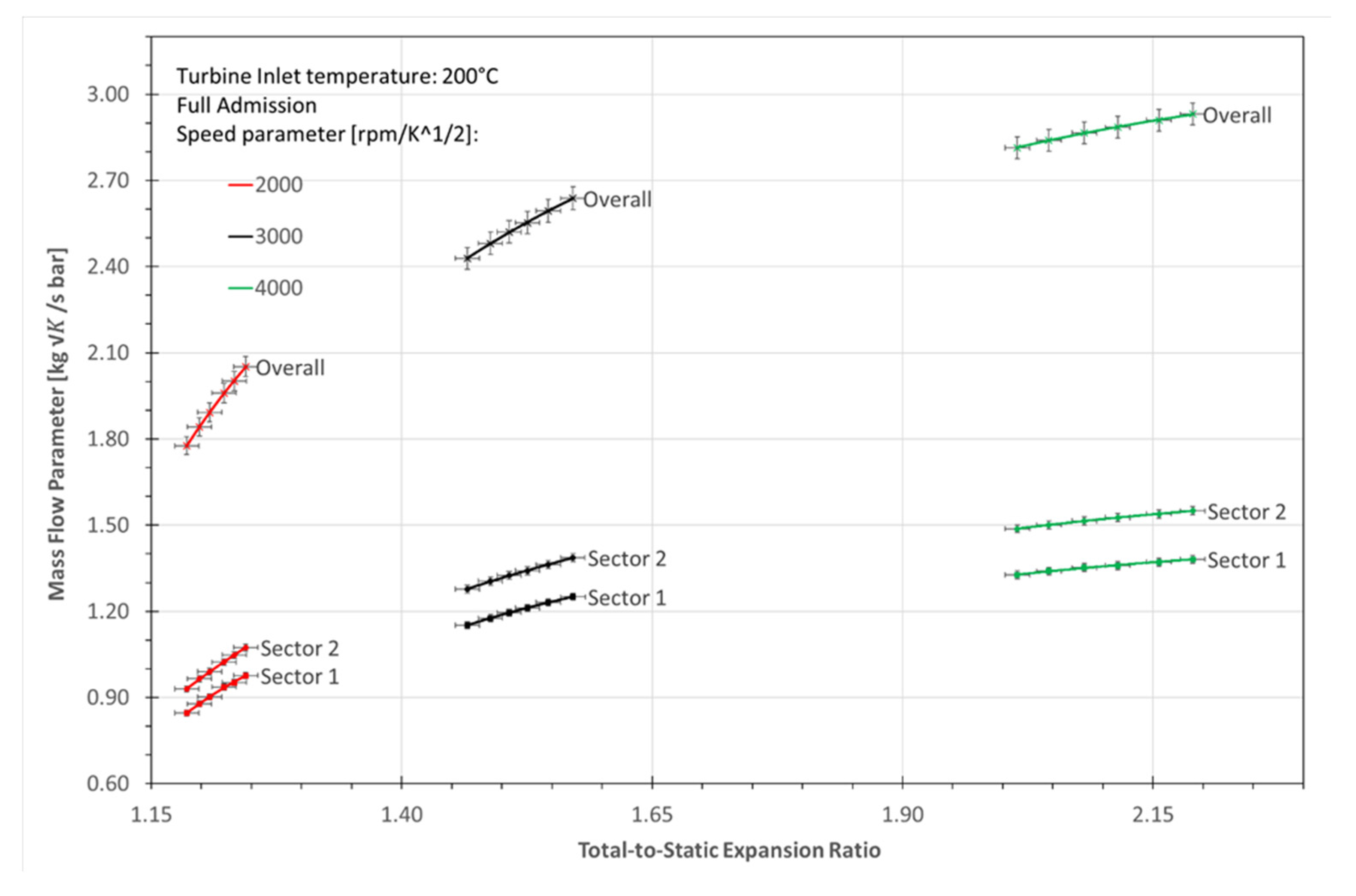
All the admission conditions are reported and compared to evaluate the twin entry turbines performance over an extended range. In
Figure 4, the Mass Flow Parameter, referring to the full and partial admission conditions, are reported for each Speed Parameter considered. It is possible to see the typical trend of turbine maps with a monotone correlation between the Mass Flow Parameter and the expansion ratio. It is apparent that the effect of the Speed Parameter causes an increase of the inlet pressure at high speed due to the centrifugal field. Moreover, the less gradient of the curves is determined by the approach to the choking zone for
. It is interesting to note the different swallowing capacity of the two sectors. It is clearly shown for each rotational speed how Sector 2 has higher swallowing capacity with respect to the Sector 1. This result is perfectly in agreement with the experimental investigations in the literature, such as the analyses by Dale and Watson [
5] or Capobianco and Gambarotta [
6]. It is also possible to highlight how the full admission condition is not definable as the sum of the partial conditions.
The trend is also confirmed in
Figure 5 where a comparison between the overall Mass Flow Parameter (MFP) and the mass flow parameter defined for each entry, previously called MFP1 and MFP2, are shown in full admission condition. Additionally, in this case, with the throttle valves on the turbine feeding lines fully open, Sector 2 is characterized by a higher swallowing capacity.
Thanks to the layout configuration of the test bench, it is interesting to identify a specific unequal admission condition that reflects the same swallowing capacity in Sector 1 and Sector 2. The overall Mass Flow Parameters in comparison with MFP1 and MFP2 versus the expansion ratio are plotted in
Figure 6. Throttle valves are controlled to impose a ratio of the mass flow rate in both branches equal to the unity. This case is initially studied for the lower value of the Speed Parameter (
). It is important to highlight how the curves for Sector 1 and Sector 2 overlap. In this way, the asymmetrical geometry of the twin-entry turbine tested, which normally causes a ratio of the flow rate equal to 0.9
, is avoided.
However, this test is also performed for each Speed Parameter considered. An interesting result is reported in
Figure 7. The three Mass Flow Parameter at
versus the expansion ratio is reported.
In contrast with the result obtained in
Figure 8, differences occur between MFP1 and MFP2. Despite having imposed the same condition that in the previous case causes an equal swallowing capacity in the two entries, slight differences are found for increased rotational speed levels. These results may be explained considering the geometrical asymmetry of the twin-entry turbine tested. By consulting the features provided from the manufacturer reported in
Table 1, it emerges that the two sectors have a quite different area. Moreover, there is no clear information or details on the volute path. It is reasonable to think that the impact of head losses become more significant with the increasing of the rotational speed, and consequently, the flow speed. The effect of a small asymmetry could be simply bypassed by introducing a specific unequal admission at lower speed level, but the contribute of velocity is becoming important at higher rotational speeds.
Figure 8 shows the progressive impact starting from a rotational speed of
to
.
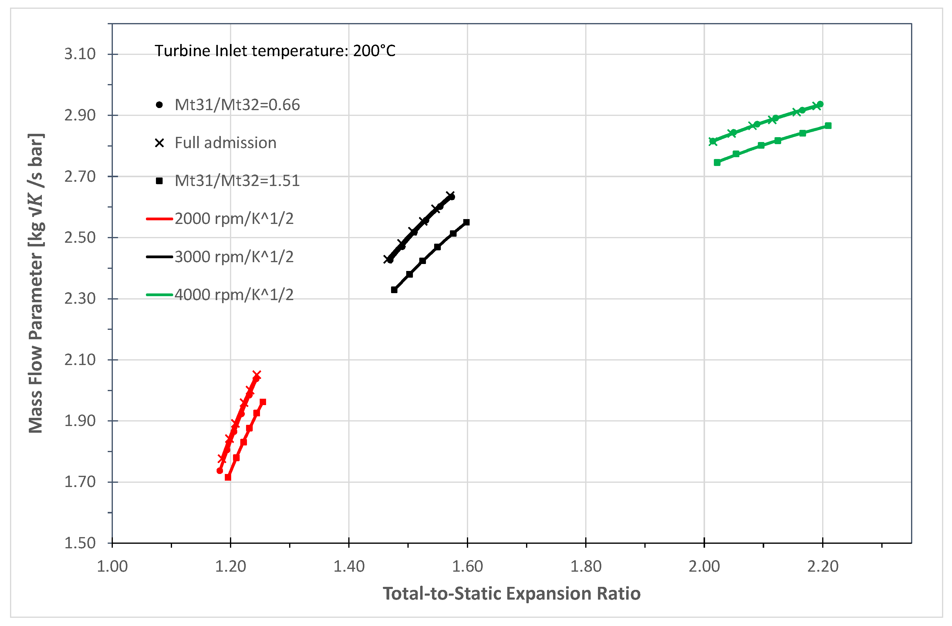
The evidence of the major swallowing capacity of the Sector 2 is confirmed in every different admission condition tested. In
Figure 9, a comparison between the full admission condition, and two other unbalanced situations are reported determined by imposing in one case a ratio
, and in the other
. The overall Mass Flow Parameter (MFP) versus the expansion ratio for the three Speed Parameter tested is shown. It is worth to notice how, in the unequal admission that provides a higher mass flow rate in the Sector 2, the curves are completely closed to the full admission condition for
and for
and a nearly total overlap is found for the highest rotational speed. A ratio of
is enough to determine a very similar admission condition to the full. On the other hand, the test is also performed for the opposite admission condition, by imposing a ratio that is exactly the reciprocal of the previous one. In this case, for
, the difference in the Mass Flow Parameter in comparison with the Full Admission condition is apparent.
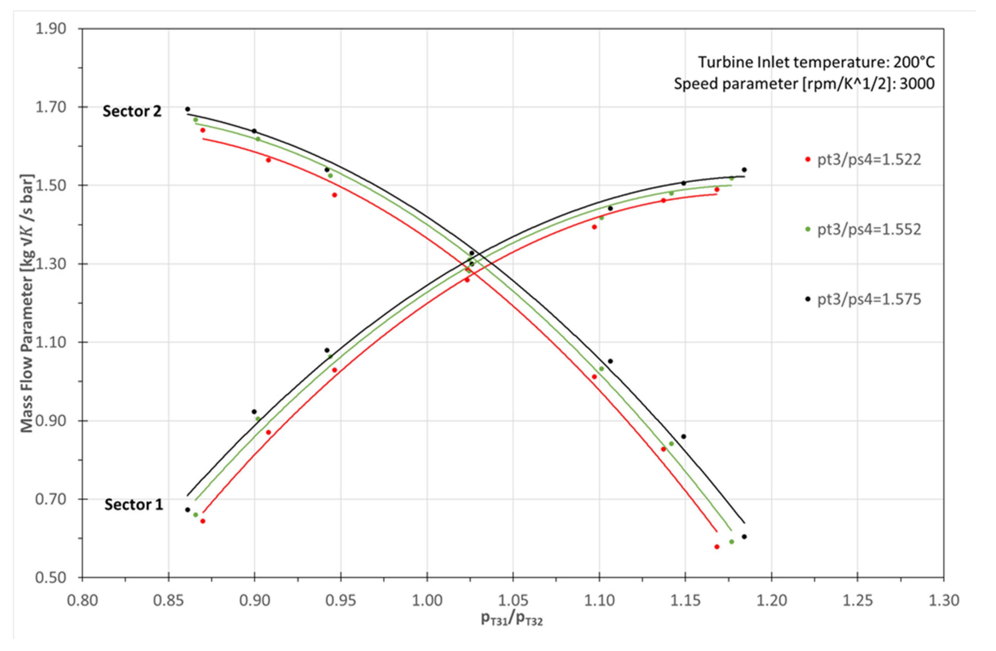
In
Figure 10, the trend of the Mass Flow Parameter evaluated for Sector 1 and Sector 2 as a function of the inlet pressure ratio
of each entries at
Each curve is characterized by a different value of the expansion ratio. The existence of a strong interaction between the two sectors is evident. Moreover, the influence of the inlet total pressure ratio on the mass flow rate that flows in each entry is apparent. As regards the MFP1, an increasing of the total pressure ratio determines an increase of the flow rate in the first sector, and consequently, a decrease in the other sector. Maximum values of MFP1 occur for the total pressure ratio higher than the unity, while the MFP2 reaches its minimum value. The same analysis can be executed, on the other hand, for Sector 2 while for values less than the unity of the total pressure ratio, the air mass flow rate (and consequently MFP2) is characterized by maximum values and the opposite situation occurs for higher
.
It is worth to evidence that the same flow rate condition in the sectors, identifiable by the intersection of the curves, occurs for an inlet total pressure ratio higher than the unity due to the asymmetrical geometry of the turbine. In this operating condition, the expansion ratio has an important role. All reported curves are characterized by an increased expansion ratio (from red to blue lines). The intersection is moved towards higher values of . The major swallowing capacity of Sector 2 is also confirmed by identifying the condition; the Mass Flow Parameter of the second sector is always over for each expansion ratio considered.
As regards the efficiency evaluation, it is important to remark that at the turbine outlet, due to the nature of the flow, the temperature has a radial non-uniform distribution [
23]. This is the reason why the efficiency cannot be estimated directly. The use of the thermomechanical efficiency is consolidated. However, this method involves compressor power, estimated by passing through the temperature measured in the upstream and downstream section. The presence of heat exchange due to the different temperature between turbine, compressor, and lubricating oil circuit could determine a temperature increase at the compressor outlet and an error in its power evaluation. This effect causes overestimated thermomechanical efficiency levels, more significant at lower rotational speed (
Figure 11).
Considering a real matching between a turbocharger and an internal combustion engine, pressure pulses always determine an unbalanced condition for the twin-entry turbine with different degrees of the ratio between the mass flow rate in the two sectors. A good knowledge of the turbine response is, thus, fundamental for prediction models.
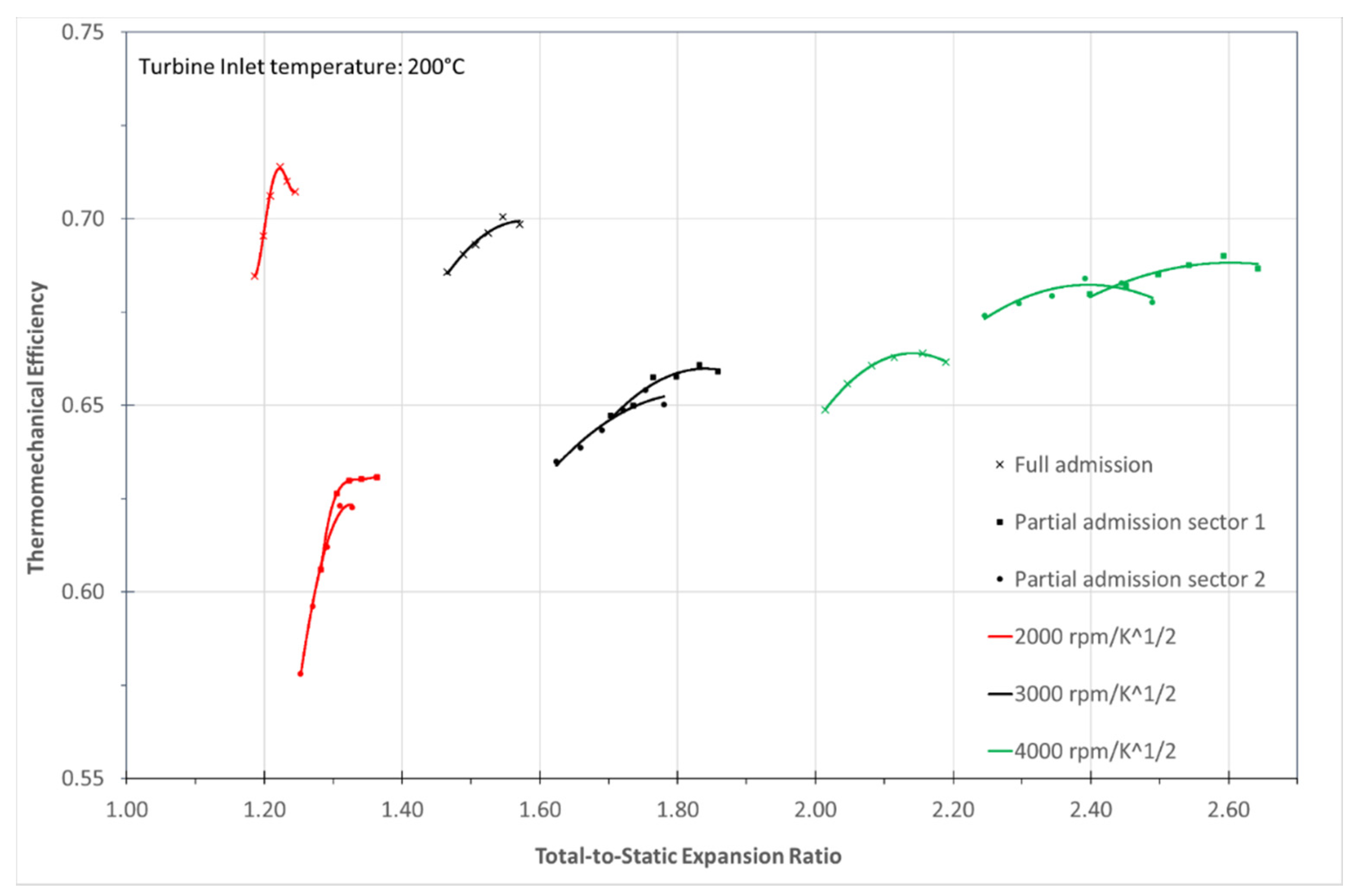
In
Figure 12 thermomechanical efficiency versus the expansion ratio is reported for partial and full admission conditions. As described by Pischinger and Wunsche [
4], the advantages in terms of the efficiency provided by the full admission condition versus the partial admission condition decrease for high rotational speeds. The reason could be explained considering, in partial admission, the reduction of frictions and the lower wet surface despite an increasing of the fluid velocity. Mixing losses, which became more prominent for high rotational speeds (i.e., higher mass flow), have an important role and, in full admission, this additional kind of loss is introduced with respect to the partial admission. The higher performance of Sector 1 could be explained considering that the better capacity to expand from the nozzle to the leading edge produces lower windage losses. Moreover, the behavior of the thermomechanical efficiency suggests a greater importance assumed by the aerodynamics efficiency with respect to the mechanical losses.
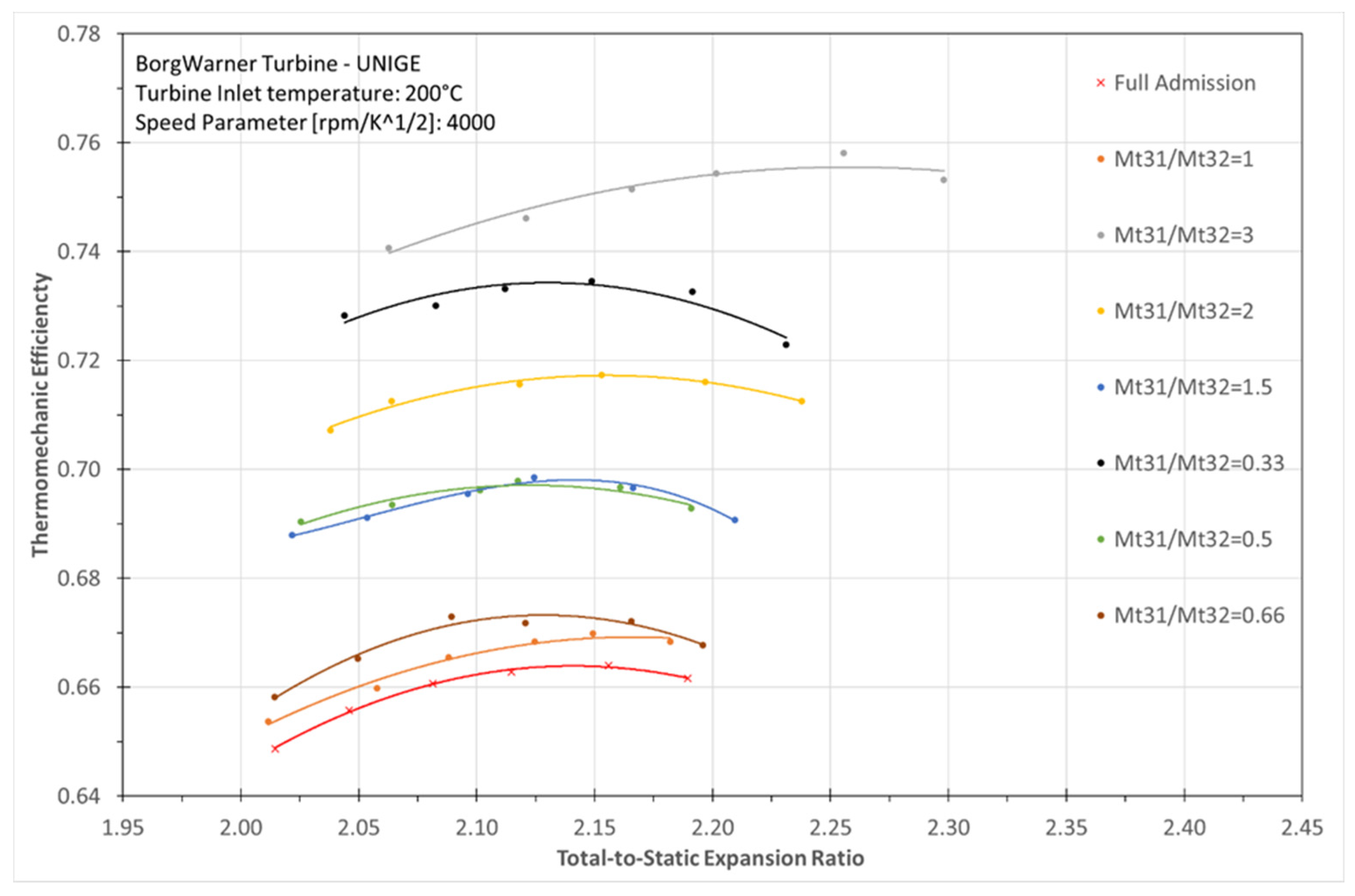
In
Figure 13, each curve is plotted for a different unequal admission condition. It is interesting to analyze how all unbalanced conditions are characterized by higher efficiency than the full admission case. It is worth to notice that, excluding the full and the
conditions, each ratio also involves its reciprocal.
Focusing on the strongest unbalanced conditions that occur for and its reciprocal , the highest efficiency values are obtained. This represent the condition where in an entry the mass flow rate is very low, but not zero. This phenomenon could be explained by considering the reduction of the windage losses in the rotor for these feeding conditions. Moreover, Sector 1 is also characterized by more important weight on the efficiency evaluation. Lower efficiency value occurs in correspondence with the reduction of unbalanced degree, the equal admission condition, and then the full admission case. A higher efficiency level is reached when the flow rate ratio is over the unity (with respect to the reciprocal value) for each admission condition.
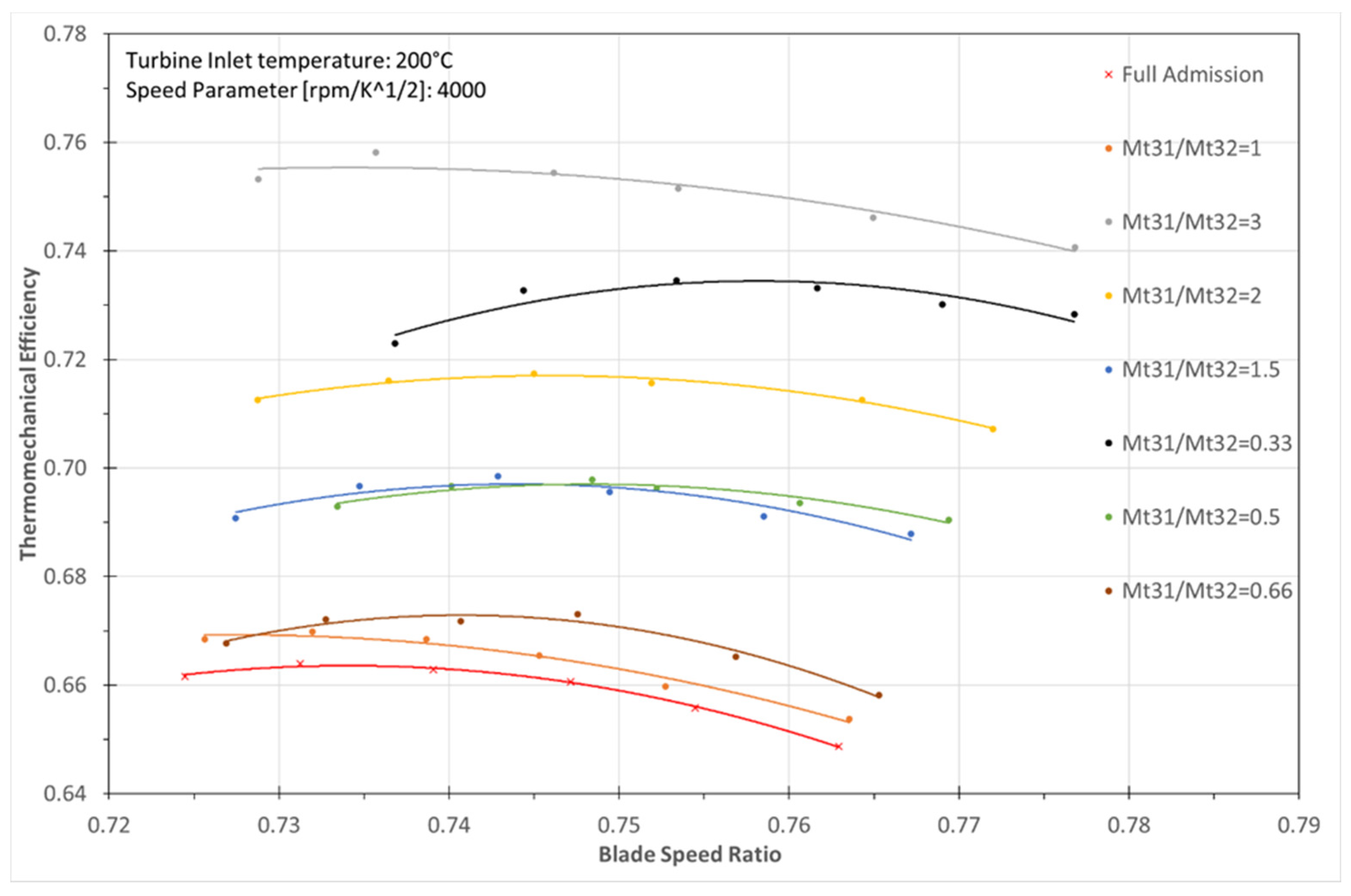
Figure 14 reports the thermomechanical efficiency plotted versus the Blade Speed Ratio, confirming the same consideration mentioned above.
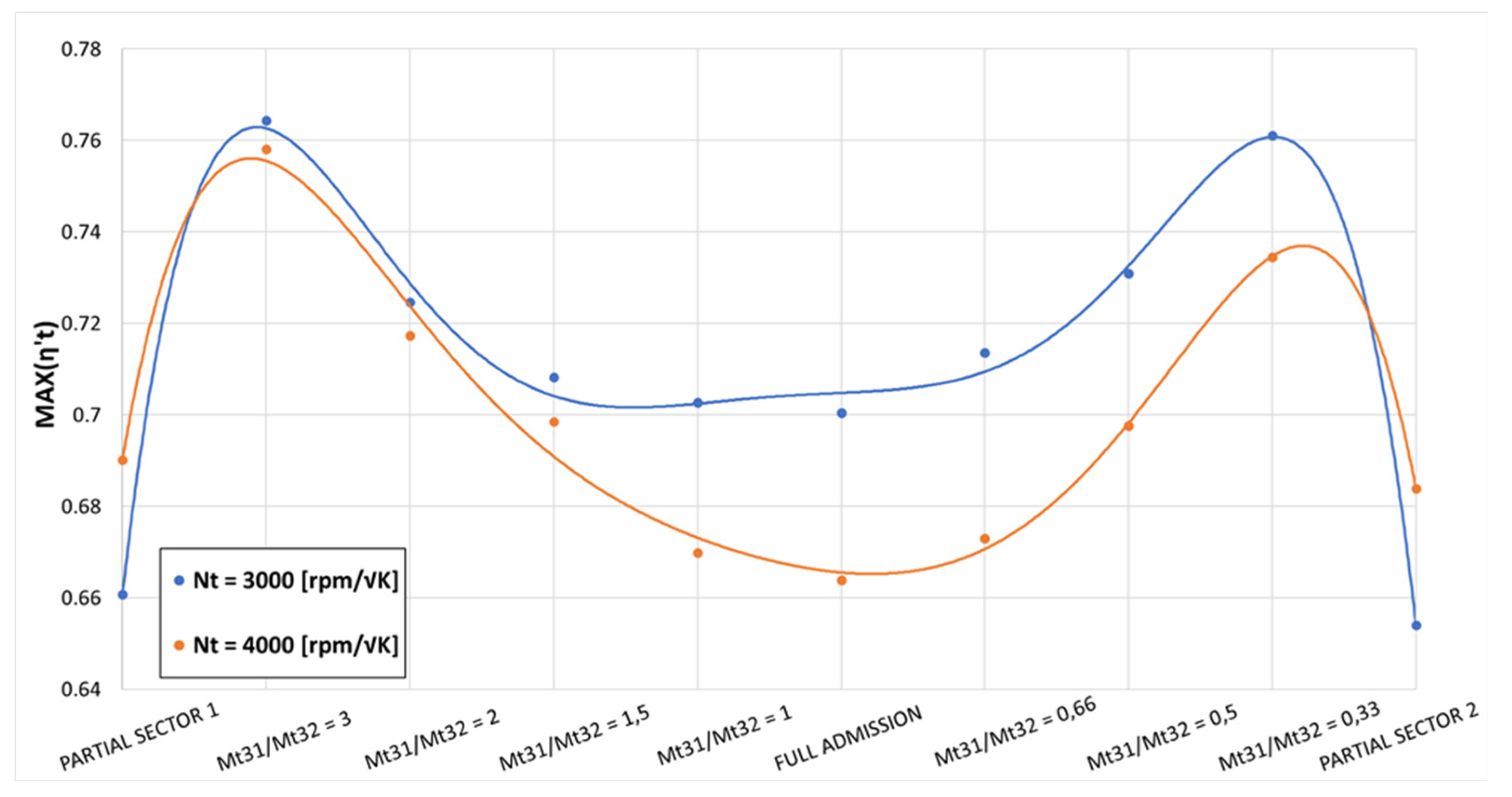
The last consideration concerns the maximum value of the thermomechanical efficiency under the different admission conditions, of which the trend is shown in
Figure 14. As previously mentioned, strongly unbalance degrees reach higher efficiency values due to the lower effect of interaction between the two sectors. Once again, it is confirmed the lower turbine performance in full admission condition compared to the unbalanced admission conditions mainly related to the strong impact of the mixing losses. Moreover, it is interesting to note the strong decrease of the thermomechanical efficiency passing from an extreme unbalanced admission (Mt31/Mt32 = 3 or Mt31/Mt32 = 0.33) to a partial admission condition.
5. Conclusions
The adoption of twin-entry turbines is becoming increasingly important today. The extensive use of pulse turbocharging for internal combustion engine with more than four cylinders lends itself well to the introduction of twin-entry turbines in order to improve efficiency and reduce pumping losses. Considering the actual working conditions of an automotive engine, periodic opening and closing of the exhaust valves produces a series of pressure pulses. The exhaust ducts are isolated on the basis of the firing order of the cylinders. For this reason, a twin-entry turbine works most of the time under unequal admission conditions. Knowledge of the turbine behavior in such conditions is a fundamental requirement to optimize the matching calculation between the turbocharger unit and the engine. However, in the literature, in these operating conditions, very little research and few experimental campaigns have been carried out to determine the twin-entry turbines’ performance. Furthermore, most of the prediction model studied in recent years need to be validated by accurate experimental data under extended working conditions.
The result of an experimental activity on a twin-entry turbine fitted in an automotive engine for heavy duty vehicles is presented. Steady performance is measured with reference to full, partial, and unequal admission conditions.
The results show that the two entries are significantly different both in terms of mass flow rate and efficiency. It is apparent that Sector 2 is characterized by a greater swallowing capacity than Sector 1. This phenomenon is confirmed by an extensive study based in the first instance on the comparison between full and partial admission conditions. Hence, the second phase is developed by imposing different degrees of unequal admission. All results are in agreement with the results available in the open literature. The different behavior can be explained by considering the rotor and housing geometry, characterized by a slight, but significant, asymmetry.
This paper also presents the strong interactions between Sector 1 and Sector 2. The mass flow rate in each entry is affected by the total inlet pressure ratio . It is established that an increase in the mass flow rate in one sector causes a decrease in the other.
As far as efficiency is concerned, sectors appear to play an important role in determining the maximum values region. For the conditions tested, the highest efficiency value is obtained not for full admission conditions, but for a ratio of the flow rate in the two entries, which determines a low mass flow rate in Sector 2.
In further works, 1D modeling of the turbocharger turbine under different admission conditions in GT Power commercial code will be developed in order to optimize the turbocharger-engine matching. Furthermore, to limit inaccuracies in the definition of turbine efficiency, a special device designed by the authors will be adopted to allow the direct measurement of the turbine isentropic efficiency thanks to a more homogeneous flow structure at the turbine outlet.


