Article

Energy and Exergy Analyses of Adsorption Chiller at Various Recooling-Water and Dead-State Temperatures

by
Ahmad A. Alsarayreh
1,*,
Ayman Al-Maaitah
2,
Menwer Attarakih
3 and
Hans-Jörg Bart
4
1
Precision Industries, P.O. Box 37448, Dubai, United Arab Emirates
2
Wahaj Investment L.L.C., 24B St, Comm-365, Ind 2-Dubai, United Arab Emirates
3
Department of Chemical Engineering, University of Jordan, Queen Rania St, Amman 11942, Jordan
4
Thermische Verfahrenstechnik, TU Kaiserslautern, 67653 Kaiserslautern, Germany
*
Author to whom correspondence should be addressed.
Energies 2021, 14(8), 2172; https://doi.org/10.3390/en14082172
Submission received: 18 March 2021 / Revised: 6 April 2021 / Accepted: 9 April 2021 / Published: 13 April 2021

Abstract

:
We conducted energy and exergy analyses of an adsorption chiller to investigate the effect of recooling-water temperatures on the cooling capacity and Coefficient of Performance (COP) with variable cycle modes. We investigated both the effect of the recooling-water temperature and the dead state temperature on the exergy destruction in the chiller components. Our results show that there is an optimum reheat cycle mode for each recooling-water temperature range. For the basic single stage cycle, the exergy destruction is mainly accrued in the desorber (49%), followed by the adsorber (27%), evaporator (13%), condenser (9%), and expansion valve (2%). The exergy destruction for the preheating process is approximately 35% of the total exergy destruction in the desorber. By contrast, the precooling process is almost 58% of the total exergy destruction in the adsorber. The exergy destruction decreases when increasing the recooling-water and the dead state temperatures, while the exergy efficiency increases. Nonetheless, the exergy efficiency decreases with an increase in the recooling-water temperature at fixed dead state temperatures. The effect of the mass recovery time in the reheat cycle on exergy destruction was also investigated, and the results show that the exergy destruction increases when the mass recovery time increases. The exergy destruction in the adsorbent beds was the most sensitive to the increase in mass recovery time.

1. Introduction

The worldwide demand for cooling equipment is growing rapidly due to population growth, increased living standards, and rising temperatures due to climate change. Space cooling accounted for about 8.5% of world electricity consumption in 2019, and the electricity demand for space cooling is expected to increase by 50% by 2030 if there is no major efficiency improvement [1]. The vapor–compression refrigeration cycles driven by electricity have the main global market share for air conditioning [2].
Thermally driven cooling technologies, which can also be driven by solar thermal energy and/or waste heat as absorption or adsorption cooling, are among the most common energy-saving solutions for cooling applications. In addition, the thermally driven cooling technology reduces greenhouse gas (GHG) emissions and ensures a higher indoor air quality [3].
The term “thermally driven chiller cycle” describes the thermodynamic cycle in which heat is absorbed at one pressure level and raised to a higher level where it is rejected. The basic procedure of the thermally driven chiller cycle is as follows:
-
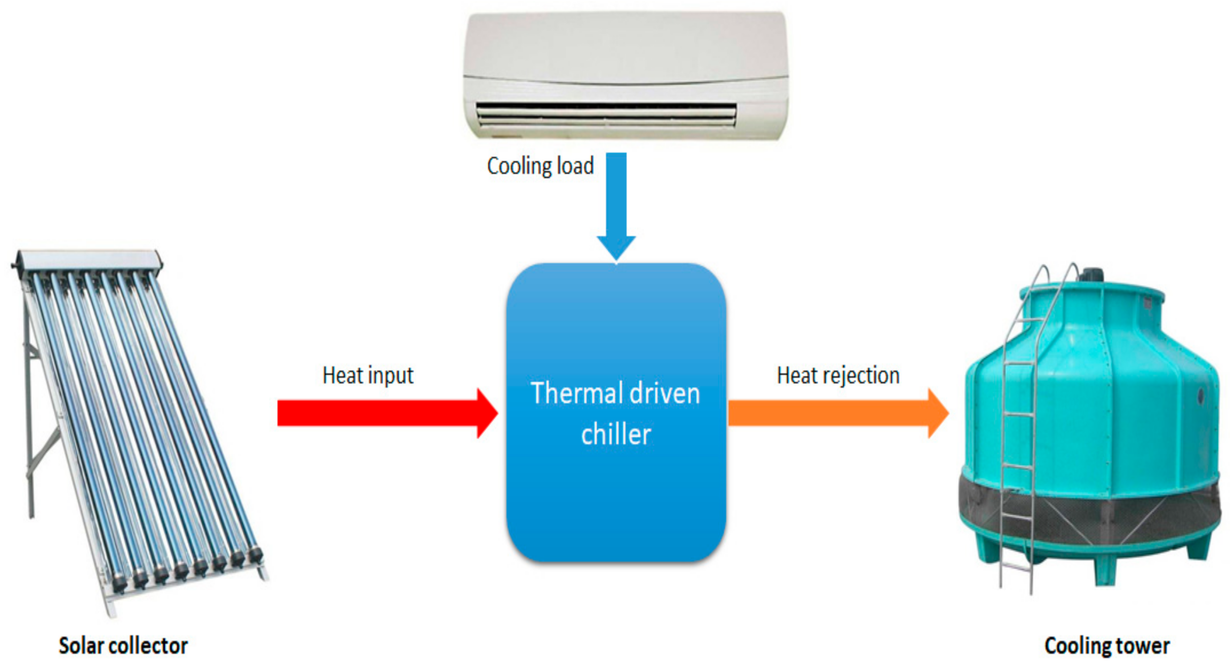
The cold air is obtained as the heat is rejected from the chilled water in the evaporator of the chiller.
-
Heat input is the heat required in the generator to drive the process, which is delivered either by the solar system or by backup heat sources.
-
Heat rejection is ideally the summation of the useful load and driving heat; it can be dissipated normally by a cooling tower or dry cooler.
Figure 1 illustrates the thermodynamic principle of the thermally driven chiller.
Adsorption cooling is considered a promising thermal cooling technology, as adsorption chillers are normally driven by low-grade heat below 100 °C with minimum electrical energy consumption [4]. The temperature can be easily achieved by the solar collector or recovered easily from the heat rejected from a diesel genset.
The principle of adsorption is based on the interaction of gases and solids. It employs the physical uptake of refrigerant (adsorbate) on the surface of the adsorbents such as silica gel, zeolite, and activated carbon due to van der Waal’s or polar bonding forces [5]. Figure 2a shows the adsorption–cooling cycle consisting of four main processes: isosteric heating, desorption, isosteric cooling, and adsorption [6]. Figure 2b illustrates a simple adsorption–cooling system, which includes four main components: an adsorbent bed, condenser, evaporator, and expansion valve. The adsorbent bed is typically cooled or heated using circulated media during the adsorption and desorption processes, respectively, to maintain a continuous adsorption–desorption cycle.
The energy performance analyses of adsorption cooling based on the first law of thermodynamics were previously investigated [7,8,9]. Many ideas to improve the system performance using adsorbent material, heat and mass recovery, multi-bed, and multi-stage technologies were introduced [10]. In general, three main working temperatures affect the adsorption cooling system performance: hot water, recooling water, and chilled water temperatures. The Coefficient of Performance (COP) and cooling capacity increase when the hot water and chilled water temperatures increase and decrease with the increase in the recooling-water temperature [11].
The first law of thermodynamics fails to account for energy quality and does not measure the irreversibility loss [12]. Moreover, energy analysis cannot help identify the irrational use of energy sources, as is the case in exergy analysis [13]; therefore, the exergy analysis of adsorption cooling systems is important in assessing the system components’ losses and efficiency. The exergy efficiency is measured as the ratio of exergy input to output in the system as useful output [14]. The remaining exergy is lost due to the irreversibility of the system [15]. The total exergy includes physical, chemical, kinetic, and potential exergies. As the major part of the exergy is physical exergy represented by the exergies due to heat, work, and mass flow, the other exergies can be neglected [16].
Not many researchers have investigated the exergy efficiency of the adsorption cooling system. Baiju and Chandrasekharan [16] performed an exergy destruction and efficiency study for solar adsorption cooling system using artificial neural network models; the predicted results of the Artificial Neural Network (ANN) model were compared with the calculated values at R close to 1 and low Root-mean-square (RMS) values. Their results showed that the overall exergy destruction increased with the increase in heat source temperature. In contrast, the overall exergy efficiency increased until it reached the optimum operating temperature and its maximum and then decreased.
Baiju and Muraleedharan [17] carried out an experimental study of a solar hybrid adsorption refrigeration system. The exergy analysis results showed that the main exergy was destroyed in the adsorbent bed due to material constraints. The expansion valve exhibited the highest exergetic efficiency, followed by the evaporator, condenser, and adsorbent bed with 79.8%, 54.7%, 42.3%, and 11%, respectively.
Ogueke and Ndeke [18] analyzed the exergy performance of an adsorption solar refrigerator by applying an exergy balance for each refrigerator component. The maximum exergy destruction occurred in the preheating and desorption process (collector/generator) followed by the evaporator and condenser.
Cao et al. [19] conducted a transient two-dimensional numerical exergy analysis of adsorption cooling cycles for three scenarios: a mass recovery cycle, heat recovery cycle, and a combination of these two cycles. Results showed that as the heat input temperature increased, the total exergy loss increased, while the exergy efficiency decreased. The mass recovery cycle improved the exergy efficiency. It reduced the total loss by 2.76% compared to that of the basic cycle, whereas the heat recovery significantly improved the exergy efficiency by 23.20%. The combined heat and mass recovery cycle showed an improvement in the exergy efficiency of 11.30% and 37.12% compared to those of the heat recovery and basic cycle, respectively.
All of the above-mentioned work on the investigation and analysis of the exergy of the adsorption chiller was mainly based on theoretical modeling results while ignoring the recooling-water temperature and assuming the dead state temperature to be constant. As the recooling temperature cannot be maintained at a low level, especially with a dry-cooled adsorption chiller, we aimed to investigate the energy and exergy of adsorption chillers at different recooling-water temperatures with different modes based on experimental results. We investigated four modes: single-stage mode, 25% of reheat mode (25% of the cooling duration), 50% reheat mode (50% of the cooling duration), and 75% reheat mode (75% of the cooling duration).

2. Methodology and Mathematical Model

The energy and exergy performance analyzed in this study is based on the experimental results for a proposed prototype adsorption chiller with a reheating process. Figure 3a illustrates the proposed chiller components, while Figure 3b shows a Clapeyron diagram of the thermodynamic processes of the adsorption chiller with the reheating process.
The adsorption chiller with the reheating process consists of two adsorbent beds, a condenser, an expansion valve, an evaporator, four non-return valves, and a motorized ball valve. The adsorbent beds work as adsorbers and desorbers. The motorized valve opens once the adsorption/desorption processes end, which allows the high-pressure hot refrigerant vapor to flow from the desorber to the adsorber (mass recovery process). The non-return valve controls the refrigerant flow and allows it to flow from the evaporator to the adsorber, and from the desorber to the condenser (Figure 3a).
The chiller works via six thermodynamics processes (Figure 3b): mass recovery with pressurization when the two beds are connected (A,B), preheating (B,C), the desorption process (C,D), mass recovery with depressurization (D,E), precooling (E,F), and the adsorption process (F,A).

2.1. Energy Performance

The cooling capacity Q c h , heat input capacity Q h o t , and the COP were calculated using Equations (1)–(3), respectively. The COP represents the ratio of the cooling output to the required amount of heat input; the COP of the chiller is calculated based on the total cycle period (tcy), which includes the periods of precooling, adsorption, preheating, and desorption.
Q c h = 0 t c y m ˙ c h w × C p c h w × T c h w _ i n T c h w _ o u t d t t c y
Q h o t = 0 t c y m ˙ h w × C p h w × T h w _ i n T h w _ o u t d t t c y
C O P = Q c h Q h o t
where:
m ˙ c h w —mass flow rate of chilled water (kg·s−1);
C p c h w —specific heat capacity of chilled water (kJ·kg−1·K−1);
T c h w _ i n —inlet temperature of chilled water (K);
T c h w _ o u t —outlet temperature of chilled water (K);
m ˙ h w —mass flow rate of hot water (kg·s−1);
C p h w —specific heat capacity of hot water (kJ·kg−1·K−1);
T h w _ i n —inlet temperature of hot water (K);
T h w _ o u t —outlet temperature of hot water (K).

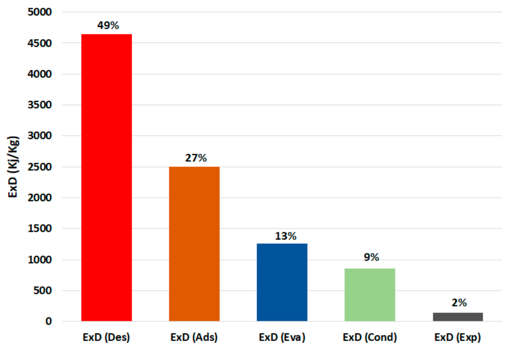
2.2. Exergy Analysis
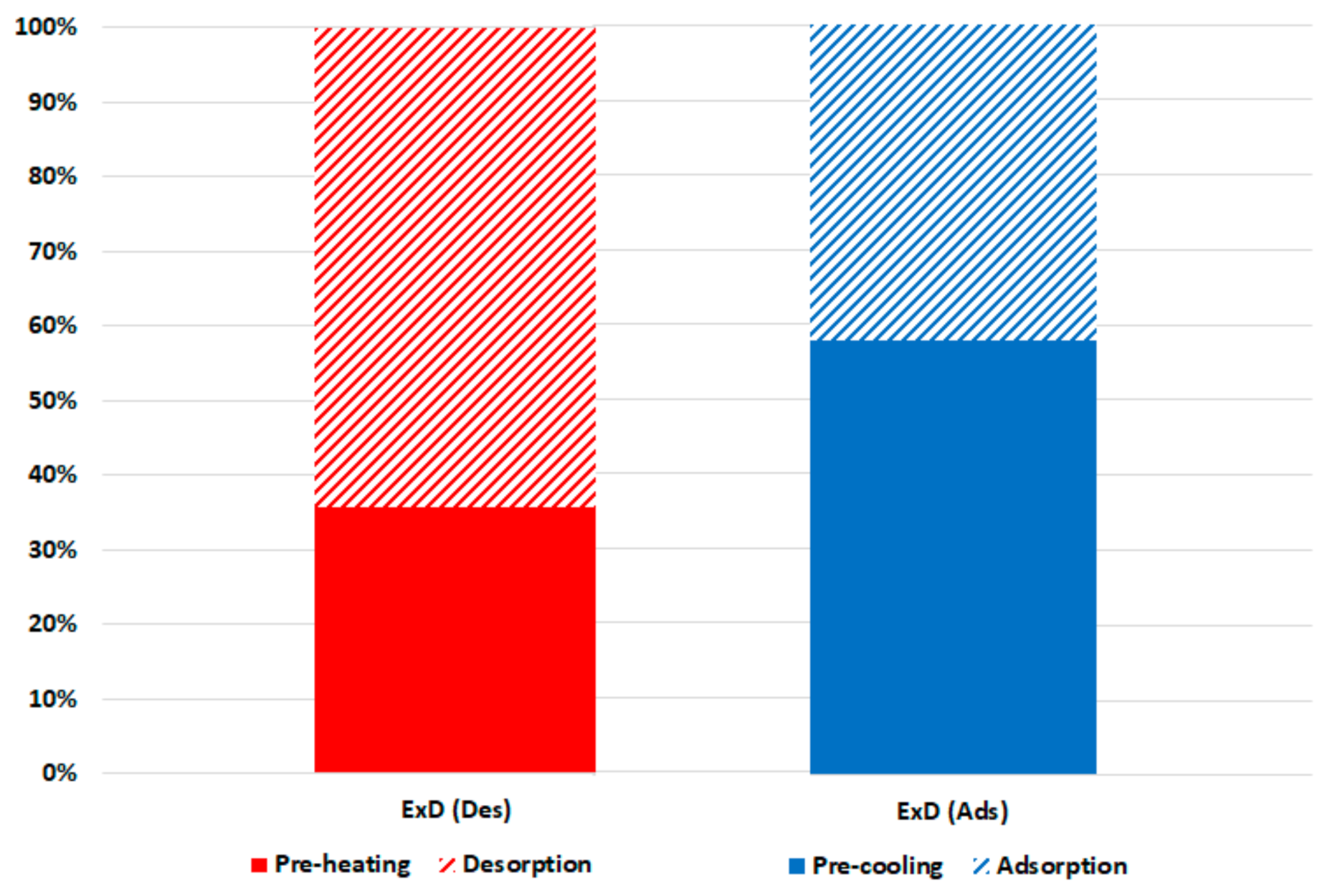
The exergy balance equation in rate form can be written as Equation (4) [20]
E ˙ x Q E ˙ x w = e x t m ˙ e x t × e x e x t i n m ˙ i n × e x i n + E ˙ x D
where:
E ˙ x Q —heat exergy (KW);
E ˙ x w —work exergy (KW);
m ˙ e x t —refrigerant outlet mass flow rate (Kg·s−1);
m i n —refrigerant inlet mass flow rate (Kg·s−1);
e x —mass flow exergy (kJ·kg−1);
E ˙ x D —exergy destruction (kJ).
E ˙ x Q is the heat exergy and can be written as Equation (5)
E ˙ x Q = 1 T 0 T h × Q ˙
where:
T 0 —dead state temperature (K);
T h —heat input temperature (K);
Q ˙ —heat transfer rate (kW).
e x is the mass flow exergy given by [21]
e x = h h 0 T 0 × s s 0
where:
h —specific enthalpy (kJ·Kg−1);
h 0 —specific enthalpy at dead state temperature (kJ·Kg−1);
s —specific entropy (kJ·kg−1·K−1);
s 0 —specific entropy at dead state temperature (kJ·kg−1·K−1).
In this study, the subscript ‘0′ represents the ambient condition.
The exergy destruction ( E ˙ x D ) in the adsorption chiller components can be calculated as per Equations (7)–(12):
-
Exergy destruction in the adsorber ( E ˙ x D . a d s ):
E ˙ x D . a d s = 1 T 0 T a d s × Q a d s ˙ + m ˙ r e f , a d s × h v . e v a h l . a d s T 0 × s v . e v a s l . a d s
where:
E ˙ x D . a d s —exergy destruction in the adsorber (kJ);
T 0 —dead state temperature (K);
T a d s —adsorbent bed temperature (K);
Q ˙ a d s —adsorption heat capacity (kW);
m ˙ r e f , a d s —refrigerant mass flow rate in the adsorber bed (Kg·s−1);
h v . e v a —specific enthalpy of the refrigerant vapor in the evaporator (kJ·Kg−1);
h l . a d s —specific enthalpy of the refrigerant liquid in the adsorber bed (kJ·Kg−1);
s v . e v a —specific entropy of the refrigerant vapor in the evaporator (kJ·kg−1·K−1).
s l . a d s —specific entropy of the refrigerant liqued in the adsorbent bed (kJ·kg−1·K−1).
-
Exergy destruction in the desorber ( E ˙ x D . d e s ):
E ˙ x D . d e s = 1 T 0 T d e s × Q ˙ d e s + m ˙ r e f , d e s × h l . d e s h v . d e s T 0 × s l . d e s s v . d e s
where:
E ˙ x D . d e s —exergy destruction in the desorber (kJ).
T 0 —dead state temperature (K);
T d e s —desorber bed temperature (K);
Q ˙ d e s —desorption heat capacity (kW).
m ˙ r e f , d e s —refrigerant mass flow rate in the desorber bed (Kg·s−1);
h l . d e s —specific enthalpy of the refrigerant liquid in the desorber bed (kJ·Kg−1);
h v . d e s —specific enthalpy of the refrigerant vapor in the desorber bed (kJ·Kg−1);
s l . d e s —specific entropy of the refrigerant liquied in the desorber bed (kJ·kg−1·K−1).
s v . d e s —specific entropy of the refrigerant vapor in the desorber bed (kJ·kg−1·K−1).
-
Exergy destruction in the condenser ( E ˙ x D . c o n d ) :
E ˙ x D . c o n d = 1 T 0 T c o n d × Q ˙ c o n d + m ˙ r e f , c o n d × h v . d e s h l . c o n d T 0 × s v . d e s s l . c o n d
where:
E ˙ x D . c o n d —exergy destruction in the condenser (kJ);
T 0 —dead state temperature (K);
T c o n d —condenser temperature (K);
Q ˙ c o n d —condensation heat capacity (kW);
m ˙ r e f , c o n d —refrigerant mass flow rate in the condenser (Kg·s−1);
h v . d e s —specific enthalpy of the refrigerant vapor in the desorber bed (kJ·Kg−1);
h l . c o n d —specific enthalpy of the refrigerant liquid in the condenser (kJ·Kg−1);
s v . d e s —specific entropy of the refrigerant vapor in the desorber bed (kJ·kg−1·K−1);
s l . c o n d —specific entropy of the refrigerant liquid in the condenser (kJ·kg−1·K−1).
-
Exergy destruction in the evaporator ( E ˙ x D . e v a ):
E ˙ x D . e v a = 1 T 0 T e v a × Q e v a ˙ + m ˙ r e f , e v a × h l . e v a h v . e v a T 0 × s l . e v a s v . e v a
where:
E ˙ x D . e v a —exergy destruction in the evaporator (kJ);
T 0 —dead state temperature (K);
T e v a —evaporator temperature (K);
Q ˙ e v a —evaporation heat capacity (kW);
m ˙ r e f , e v a —refrigerant mass flow rate in the evaporator (Kg·s−1);
h l . e v a —specific enthalpy of the refrigerant liquid in the evaporator (kJ·Kg−1);
h v . e v a —specific enthalpy of the refrigerant vapor in the evaporator (kJ·Kg−1);
s l . e v a —specific entropy of the refrigerant liquid in the evaporator (kJ·kg−1·K−1);
s v . e v a —specific entropy of the refrigerant vapor in the evaporator (kJ·kg−1·K−1).
-
Exergy destruction in the expansion ( E ˙ x D . e x p a ) :
E ˙ x D . e x p a = m ˙ r e f , c o n d × h l . c o n d h l . e v a T 0 × s l . c o n d s l . e v a
where:
E ˙ x D . e x p a —exergy destruction in the expansion (kJ);
T 0 —dead state temperature (K);
m ˙ r e f , c o n d —refrigerant mass flow rate in the condenser (Kg·s−1);
h l . c o n d —specific enthalpy of the refrigerant liquid in the condenser (kJ·Kg−1);
h l . e v a —specific enthalpy of the refrigerant liquid in the evaporator (kJ·Kg−1);
s l . c o n d —specific entropy of the refrigerant liquid in the condenser (kJ·kg−1·K−1);
s l . e v a —specific entropy of the refrigerant liquid in the evaporator (kJ·kg−1·K−1).
-
Total exergy destruction ( E ˙ x D . t o t ):
E ˙ x D . t o t = E ˙ x D . a d s + E ˙ x D . d e s + E ˙ x D . c o n d + E ˙ x D . e v a + E ˙ x D . e x p a
m ˙ is assumed to be zero during the preheating and precooling of the adsorbent bed, evaporator, condenser, and expansion valve and also during the reheat phase for the condenser, evaporator, and expansion value.
The cyclic exergy efficiency, which is the ratio of exergy output of the system to the exergy input, can be expressed as in Equation (13)
η e x = E x ( Q e v a ) E x ( Q d e s )
We have the following assumptions:
  • The water vapor (refrigerant) behaves as an ideal gas.
  • The pressure and temperature inside the adsorbent bed are uniforms.
  • Potential, kinetic, and chemical effects are neglected.
  • The expansion process is isenthalpic.
  • The pressure drop in the non-return values is neglected.
  • The chiller is well insulated, and there are no heat losses to the surroundings.

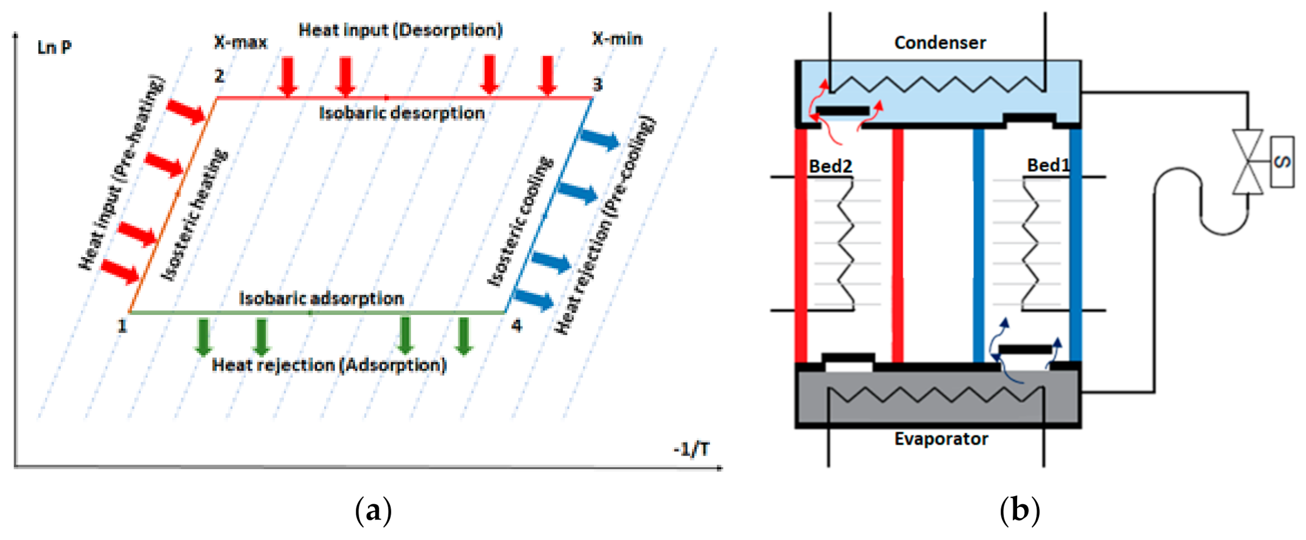
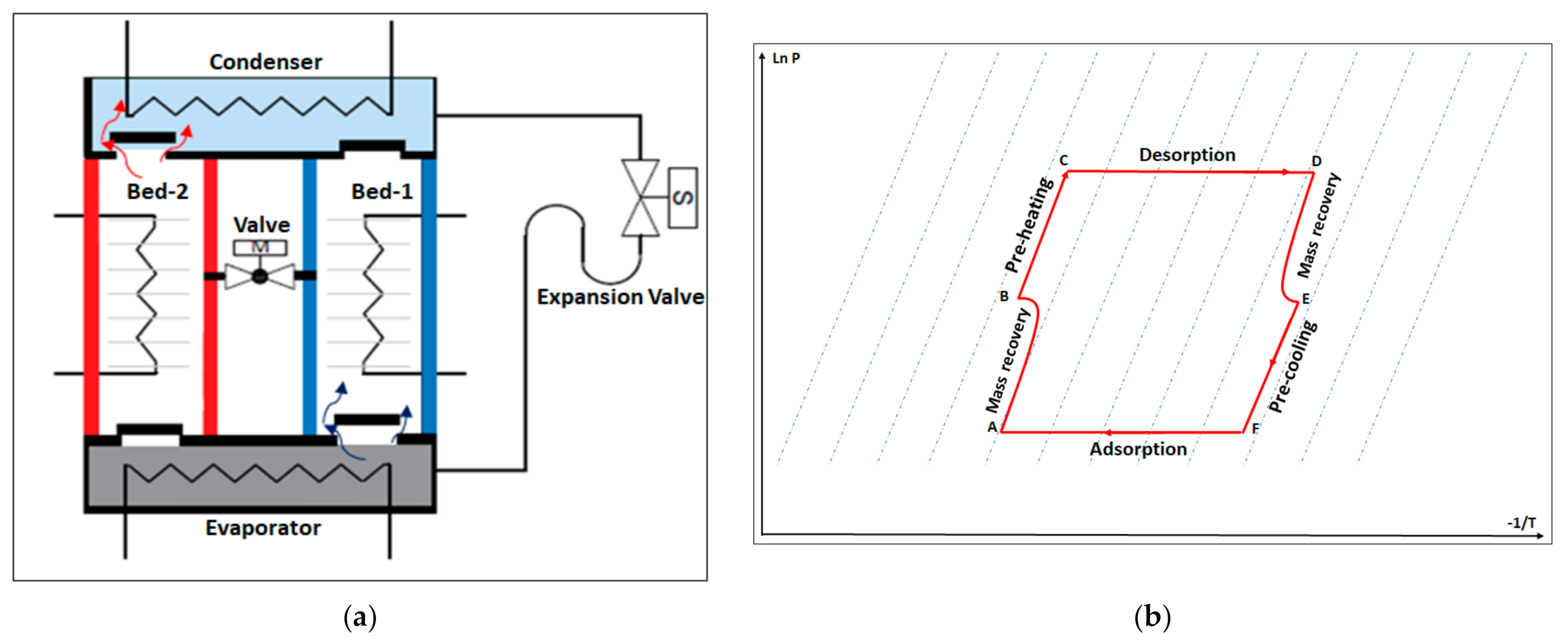
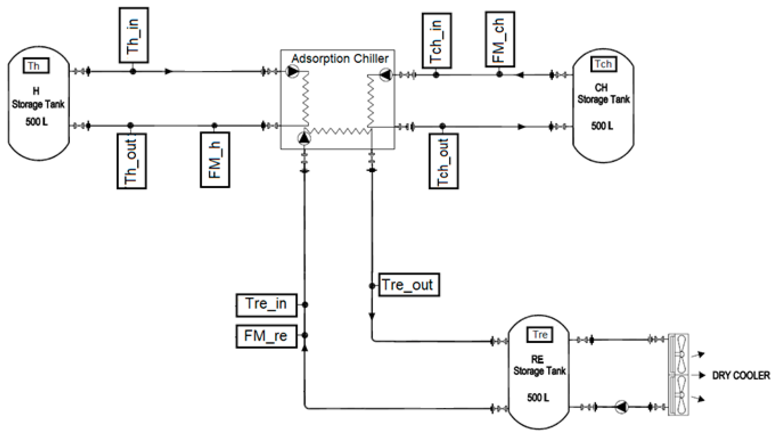
3. Experimental Setup

The proposed prototype adsorption chiller tested in this study consisted of two beds; each one has 40 kg of silicoaluminophosphates zeolite (SAPO-34) coated on copper heat exchangers. The experiment was set under the following conditions:
  • Hot water inlet temperature (Th_in) of 90 ± 0.5 °C maintained by an electric water heater.
  • Recooling-water inlet temperature (Tre_in) of 30–45 °C maintained by a dry-cooler with a 100 L buffer tank.
  • Chilled water inlet temperature (Tch_in) of 18 ± 0.5 °C maintained by an electrical heater.
  • Flow rates for hot, recooling, and chilled water are 1.2, 1.2, and 0.71 L/s, respectively.
  • Cooling cycle time duration of 550 s.
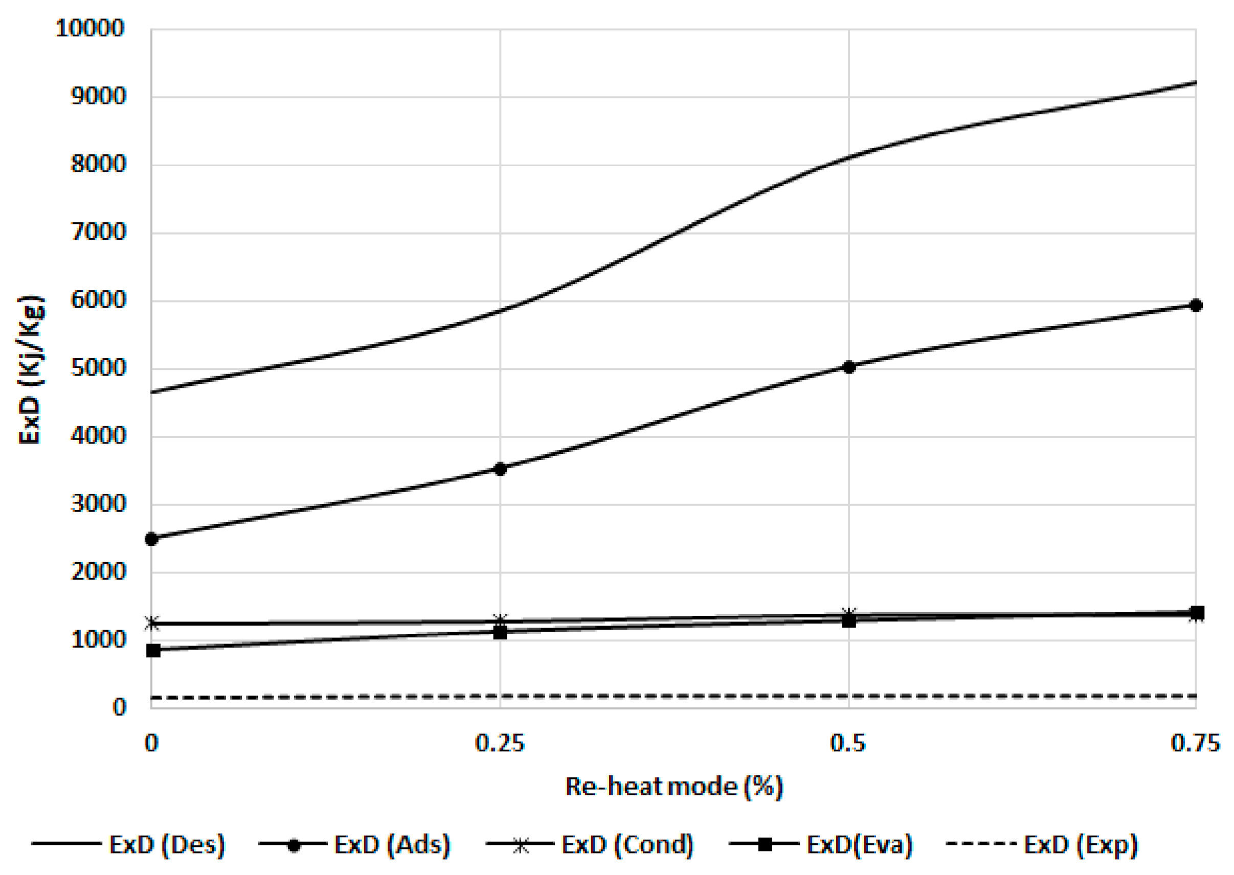
  • Four modes were investigated: single-stage mode, 25% reheat cycle mode (25% mass recovery time of the cooling duration), 50% reheat cycle mode (50% mass recovery time of the cooling duration), and 75% reheat cycle mode (75% mass recovery time of the cooling duration)
The following instrumentation setup was used to measure the experimental performance of the chiller during the reheat cycle, as shown in Figure 4. The instrument locations are described as follows:
  • Three electromagnetic flowmeters (FM_h, FM_ch, and FM_re) (manufactured by ALIA GROUP) with accuracies of ± 0.4% were used to measure the water flow rate at the hot water loop, chilled water loop, and recooling-water loop, respectively.
  • Eight platinum resistance thermometers (PT100 Class A, Pico Technology, St Neots, UK) with two temperature measuring data loggers (PT-104 is a four-channel logger) having a resolution of 0.001 °C and an accuracy of 0.015 °C were used to measure the inlet and outlet temperatures for the hot water, chilled water, and recooling water, in addition to the temperature of the storage tanks.

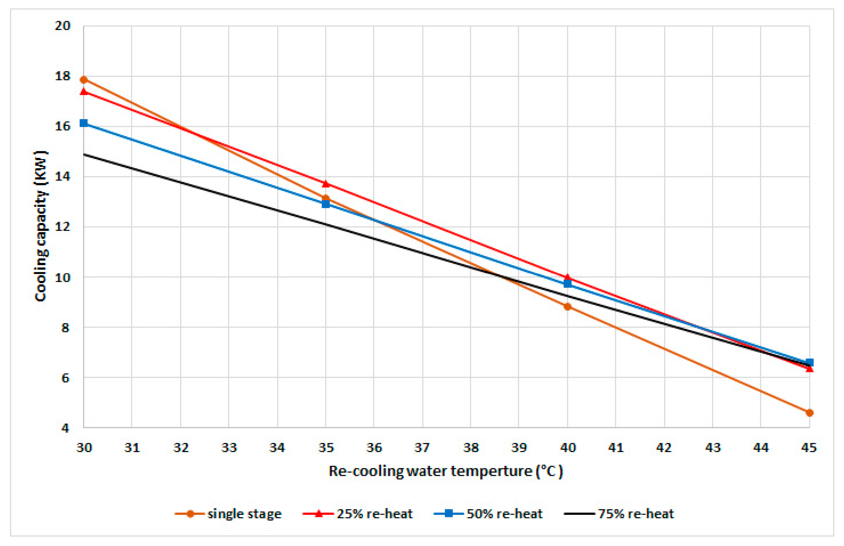
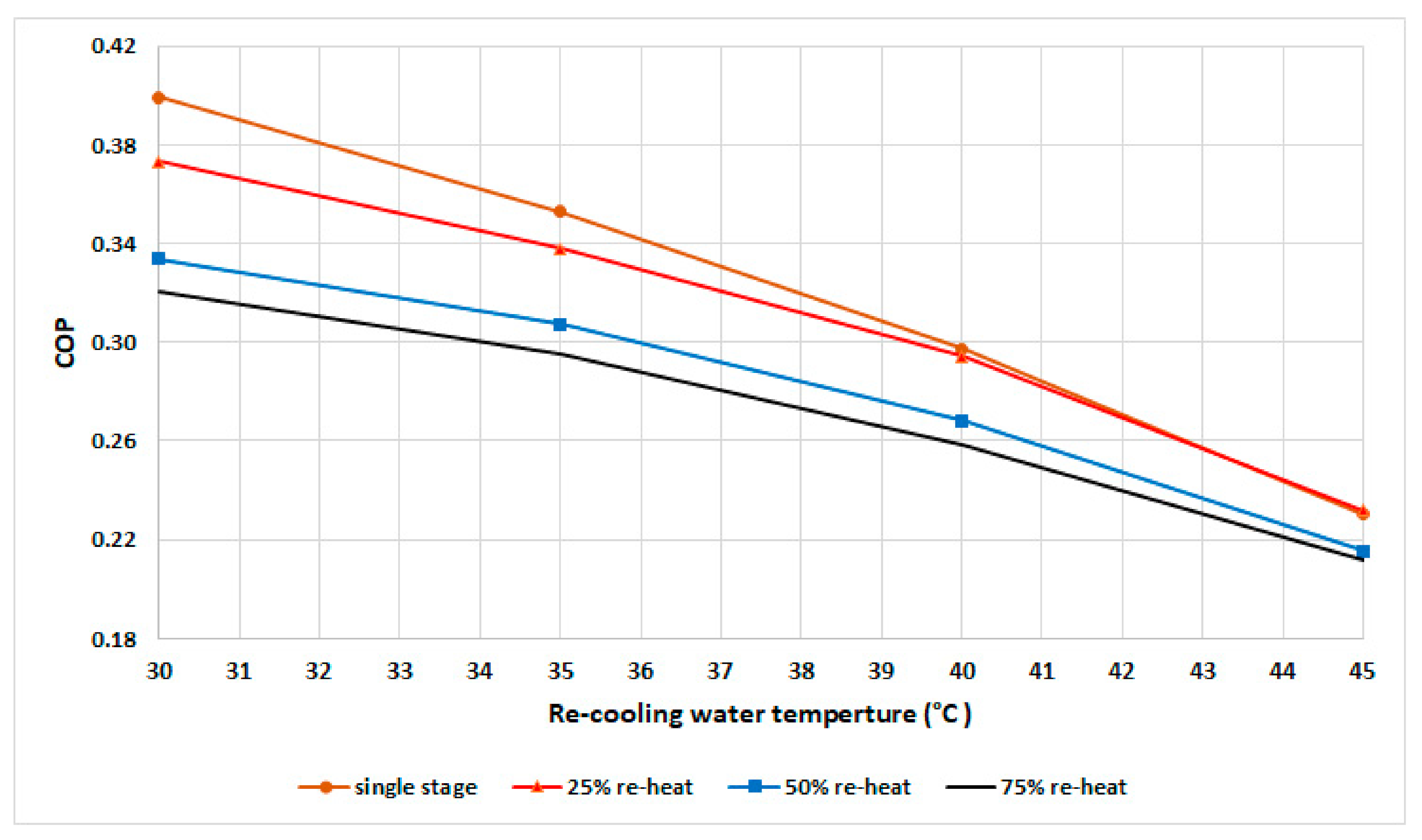
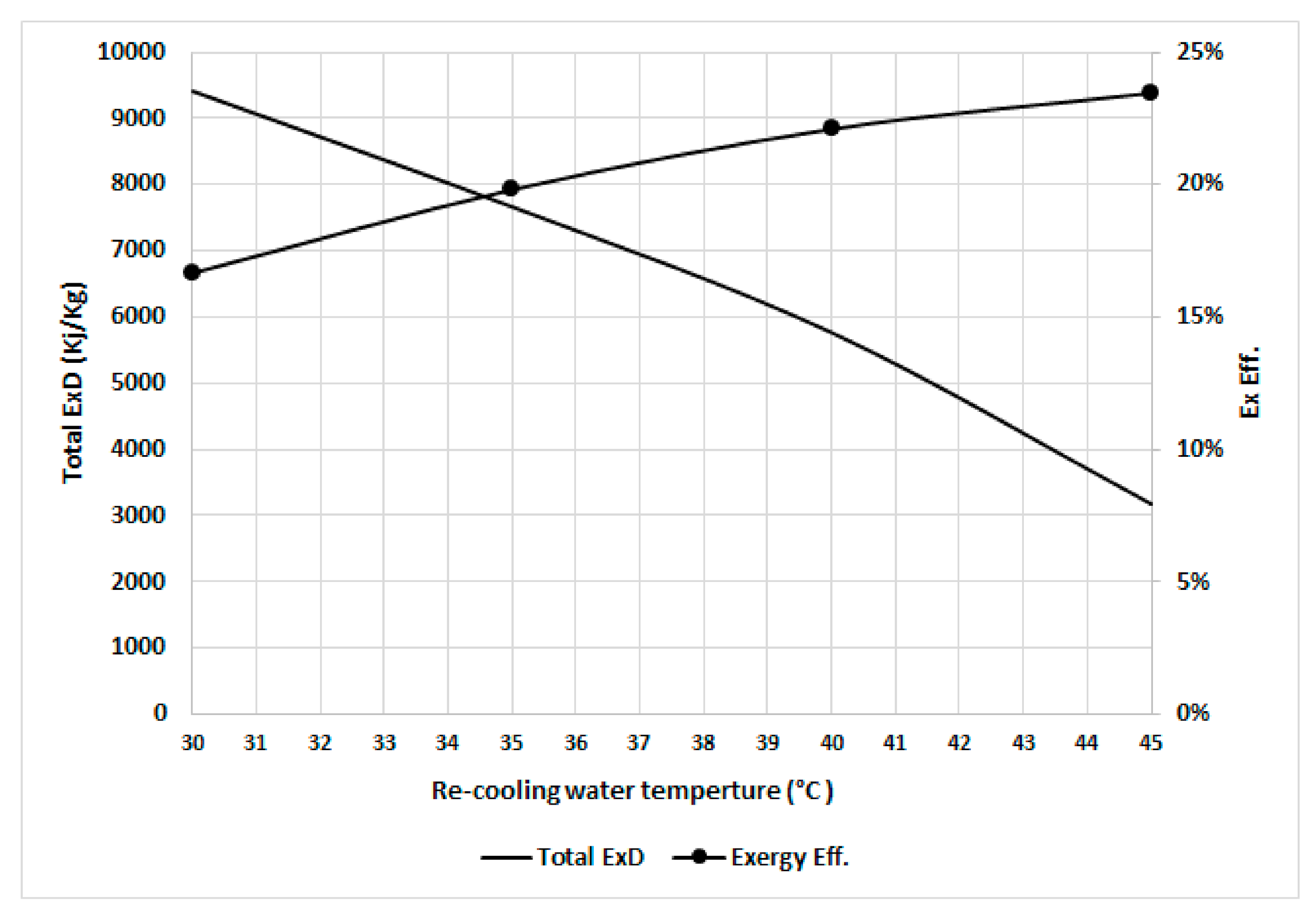
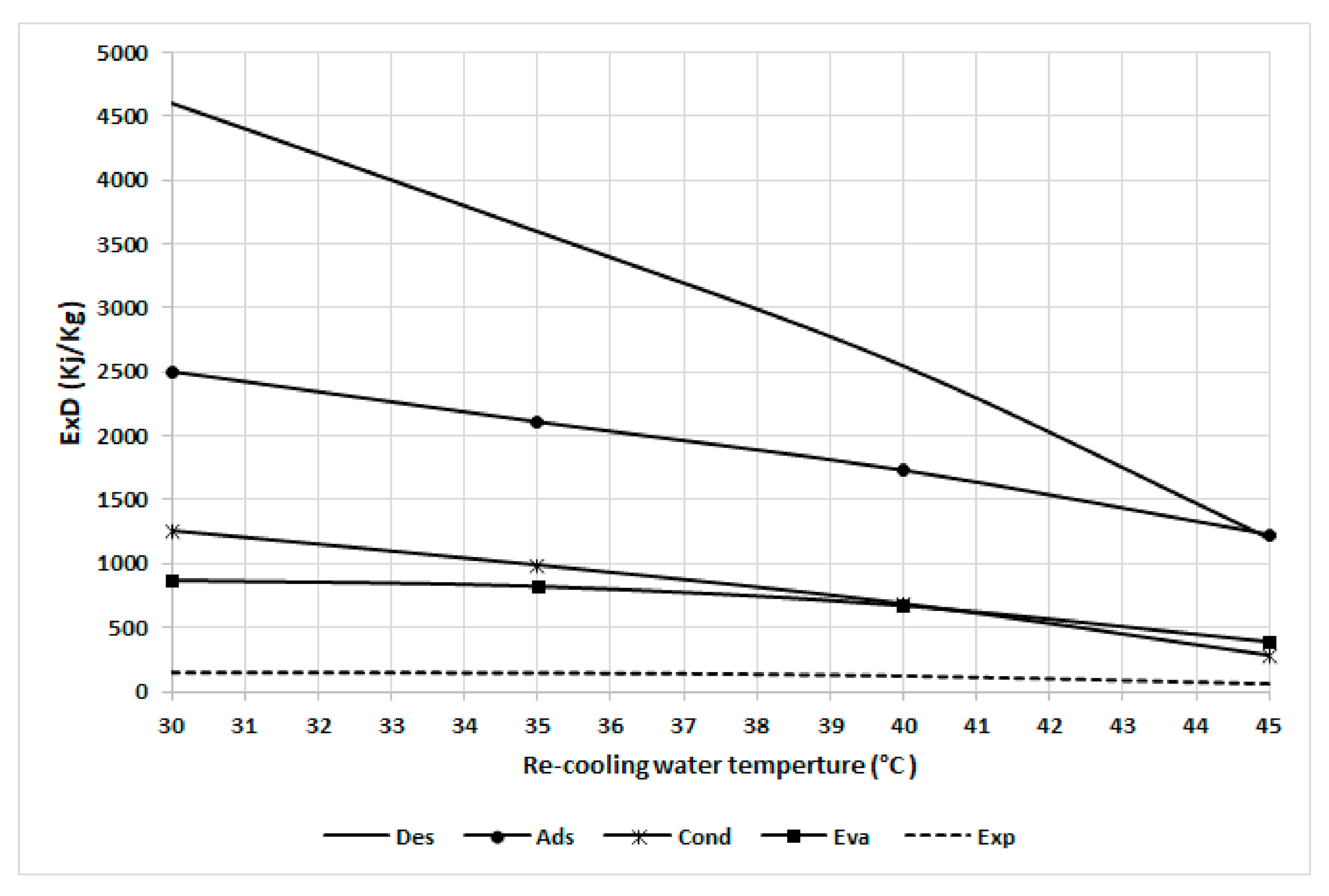
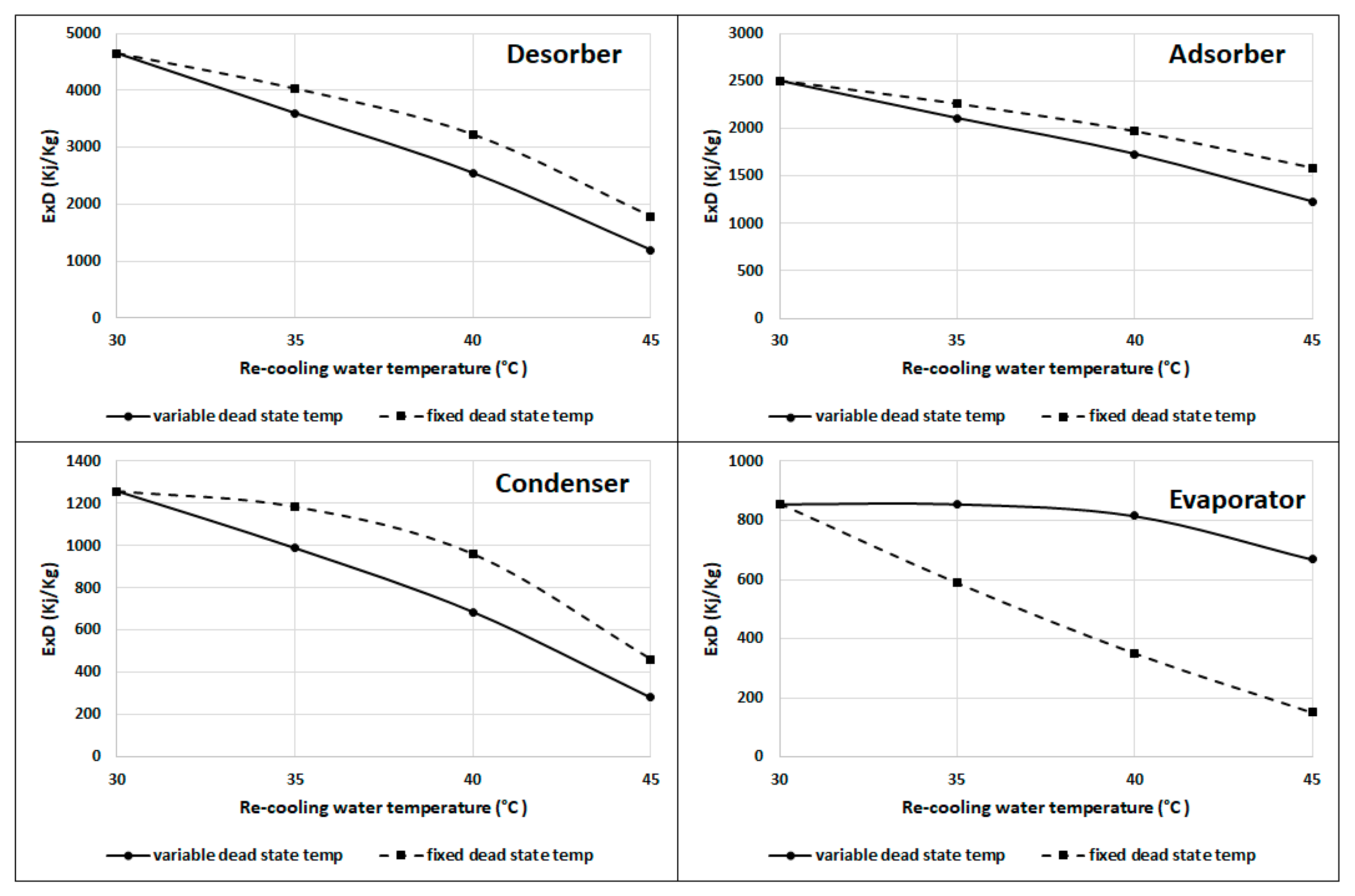
4. Results and Discussion

The cooling capacity and COP are calculated based on the experimental results as per Equations (1)–(3). The experimental temperature profile for the adsorption chiller components was exported to an excel sheet where the exergy was analyzed using Equations (4)–(13). The refrigerant properties were imported from CoolPack software (https://www.ipu.dk/products/coolpack/, accessed on 20 January 2021).
Figure 5 shows the cyclic cooling capacity at different recooling-water temperatures and modes with a fixed cyclic cooling duration of 530 s based on the experimental results for single stage and the variable reheat cycle time. The single-stage mode exhibited a better capacity at recooling temperatures below 32 °C compared to other modes. The 25% mode exhibited a higher cooling capacity within a recooling-water temperature range of 32 to 43 °C, while the 50% mode exhibited a higher capacity at temperatures higher than 43 °C.
With the increase in the recooling-water temperature, the adsorber’s uptake is decreased, which directly influences the cooling capacity. To achieve a higher capacity with the increased recooling-water temperature, the system requires a longer mass recovery time; therefore, the uptake of the adsorber is increased and that of the adsorbate in the desorber is decreased, which can be realized by increasing the pressure in the condenser as well as the recooling-water temperature and decreasing the adsorption pressure. As evident from Figure 4, there is an optimum mode for each recooling-water temperature related to the optimum water-vapor uptake and the condensation pressure. To maintain the maximum cooling capacity at different recooling-water temperatures, the chiller should be operated in the variable mode instead of conventional single-mode systems.
The experimental results of COP are shown in Figure 6 for a fixed cycle time of 530 s. The results show that the single-stage mode exhibited the highest COP at various recooling-water temperatures up to 42 °C, followed by the 25% mode. In general, the COP decreases when the recooling-water temperature increases due to the decrease in water-vapor uptake in the adsorbent bed, which leads to a decrease in the cooling capacity that is more than the heat input.
The COP of the single-stage mode is higher than that of other modes up to 42 °C, becomes equal to the COP of the 25% mode from 42 to 44 °C, and becomes slightly lower from 44 °C.
Figure 7 shows the breakdown of the exergy destruction in the proposed chiller components at 30 °C recooling-water temperature and single-stage cycle as per Equations (6)–(10). It can be noted that the highest exergy destruction is accrued in the desorber, followed by the adsorber, evaporator, condenser, and expansion valve, with proportions of 49%, 27%, 13%, 9%, and 2%, respectively. The desorber has the highest exergy destruction because of the high difference between the desorber and dead state temperatures, which are proportionally related. Another reason for higher consumption in the adsorbent bed (desorber and adsorber) is the exergy destruction in the preheating and precooling processes; as shown in Figure 8, the preheating share is around 35% of the exergy destruction in the desorber, whereas the precooling share is about 58% of that in the adsorber. The results in Figure 6; Figure 7 indicate the importance of focusing on the adsorbent bed design by minimizing the heat exchange material and improving the heat efficiency to reduce the exergy destruction in the preheating and precooling processes.
Figure 9 shows the total exergy destruction and exergy efficiency at various recooling-water temperatures (assuming the dead state temperature increases linearly with the recooling-water temperature). The total exergy destruction decreases as the input exergy of the refrigerant decreases when the dead state temperatures increase because of the decreased precooling and preheating exergy destruction, where the difference in temperatures between the desorber and adsorber is decreased. The exergy efficiency increases with increasing recooling-water temperatures because the increase in recooling-water temperature is associated with increasing dead state temperatures, which decreases the irreversibility as the desorber bed works at a temperature close to the dead state temperature.
Figure 10 shows the exergy destruction in the chiller component at various recooling-water temperatures. It can also be noted that the desorber is most sensitive to the recooling-water temperature, followed by the adsorber, condenser, evaporator, and expansion because the preheating exergy destruction decreases proportionally with the recooling-water temperature. The adsorber and condenser exhibit the same trend as they both have a constant temperature difference from the dead state temperature. The evaporator has less sensitivity to recooling-water temperature as the difference with the dead state temperature increases. The results from curves 8 and 9 clearly indicate that inefficient energy use occurs at lower temperatures and that there is a high potential for improvement at low recooling water temperatures, mainly in the adsorbent bed, via the use of a heat exchanger and time cycle optimization.
To separately investigate the effect of the recooling-water temperature on the exergy destruction, the dead state temperature is assumed constant at 25 °C regardless of the recooling-water temperature, and the result is compared to the variable dead state temperature (dead state temperature is assumed to be 5 °C less than the recooling-water temperature). Figure 11a,b show the total exergy destruction and exergetic efficiency, respectively. It can be noted that the exergy destruction decreases with increasing recooling-water temperature for fixed and variable dead state temperature. As shown in Figure 11a, it is clear that the total exergy destruction decreases with an increasing dead state temperature. The exergetic efficiency curves of Figure 11b show that the fixed dead state temperature exhibits the opposite trend compared to the variable dead state temperature.
The exergetic efficiency decreases when increasing the recooling-water temperature at a fixed dead state temperature of 25 °C, mainly because the input exergy destruction increases as the difference between dead state and recooling temperatures increases; however, the exergetic efficiency increases as the dead state temperature increases even at higher recooling temperatures.
Figure 12 shows that the desorber, adsorber, and condenser have more exergy destruction at fixed dead state temperatures than those at the variable dead state temperature; however, the evaporator has lower exergy destruction at the fixed dead state temperature than the variable dead state temperature, as the difference is constant between the evaporator and dead state temperatures at fixed temperatures. The results from Figure 10 and Figure 11 indicate that it is better to work at a recooling water temperature near to the ambient or dead state temperature if achievable. Table 1 summarizes the recooling water increase effect on the exergy destruction and efficiency for Figure 8, Figure 9, Figure 10, Figure 11, Figure 12.
Next, Figure 13 shows the effect of the reheating cycle time for the exergy destruction of the chiller component. The exergy destruction increases with an increase in the reheat cycle time as more exergy will be added during the mass recovery. Adsorbent beds (adsorber and desorber) are more sensitive to this effect as they are directly affected by more exergy input in the bed during the mass recovery process. The evaporator and condenser are less sensitive than adsorbent beds because the effect is due to the cooling capacity and exergy output.
Figure 14 demonstrates that the exergy efficiency increases with recooling-water temperature, as explained previously when discussing Figure 11. The exergy efficiency increases with an increase in the recooling-water temperature, mainly due to increased dead state temperature. The exergy efficiency increases sharply with recooling-water temperature up to 40 °C. Higher recooling-water temperatures have a lower effect as the refrigerant uptake decreases sharply for this type of zeolite. As such, this will increase the exergy destruction ratio. The results from Figure 13 and Figure 14 indicate that while increasing the mass recovery time improves the cooling capacity, this, on the other hand, also increases the exergy destruction and reduces the exergy efficiency. As such, an optimization analysis of the mass recovery time and cooling capacity should be conducted in order to select the optimum mode.

5. Conclusions

The energy and exergy analyses of the adsorption cooling cycle at various recooling-water temperatures were investigated based on the experimental results with different cycle modes. The cooling capacity and COP were found to decrease with increasing recooling-water temperatures. An optimum mode for each recooling-water temperature range was found depending on the cooling capacity and COP. In addition, exergy destruction for each component of the chiller was analyzed based on the experimental data. The highest exergy destruction occurred in the desorber, followed by the adsorber, evaporator, condenser, and expansion valve with 49%, 27%, 13%, 9%, and 2%, respectively, at nominal working conditions.
The exergy destruction for the preheating process was 35% of the total exergy destruction in the desorber; however, the exergy destruction for the precooling process was 58% of the total destruction in the adsorber.
The exergy destruction and efficiency were both found to decrease with increasing recooling-water temperatures at fixed dead state temperatures. The exergy destruction was found to decrease with an increasing dead state and recooling-water temperatures; however, the exergy efficiency increases with an increasing dead state temperature and recooling-water temperature. The results show that the exergy destruction increases with increasing the mass recovery time in the reheat cycle. The exergy destruction in the adsorbent beds was the most sensitive for the increase in mass recovery time.

Author Contributions

Conceptualization, A.A.A.; methodology, A.A.A. and A.A.-M.; software, A.A.-M.; validation, A.A.A. and A.A.-M.; formal analysis, A.A.A.; investigation, A.A.A.; resources, A.A.-M.; data curation, A.A.A.; writing—original draft preparation, A.A.A.; writing—review and editing, A.A.-M.; visualization, A.A.A.; supervision, A.A.-M.; M.A. and H.-J.B. All authors have read and agreed to the published version of the manuscript.

Funding

This research received no external funding.

Institutional Review Board Statement

Not applicable.

Informed Consent Statement

Not applicable.

Data Availability Statement

Not applicable.

Acknowledgments

Not applicable.

Conflicts of Interest

The authors declare no conflict of interest.

References

  1. IEA. Cooling; IEA: Paris, France, 2020. [Google Scholar]
  2. Ayou, D.S.; Coronas, A. New Developments and Progress in Absorption Chillers for Solar Cooling Applications. Appl. Sci. 2020, 10, 4073. [Google Scholar] [CrossRef]
  3. Narayanan, R. Chapter Seven—Heat-Driven Cooling Technologies. In Clean Energy for Sustainable Development; Rasul, M.G., Azad, A.K., Sharma, S.C., Eds.; Academic Press: Cambridge, MA, USA, 2017; pp. 191–212. [Google Scholar]
  4. Rucha, P.; Salibaa, S.; Onga, C.L.; Al-Shehrib, Y.; Al-Rihailib, A.; Al-Mogbelb, A.; Michela, B. Heat-Driven Adsorption Chiller Systems for Sustainable Cooling Applications. In Proceedings of the 11th IEA Heat Pump Conference 2014 Conference Proceedings, Montreal, QC, Canada, 12–16 May 2014. [Google Scholar]
  5. Thu, K. Adsorption Desalination: Theory & Experiments. Ph.D. Thesis, National University of Singapore, Singapore, 2010. [Google Scholar]
  6. Ambarita, H.; Kawai, H. Experimental study on solar-powered adsorption refrigeration cycle with activated alumina and activated carbon as adsorbent. Case Stud. Therm. Eng. 2016, 7, 36–46. [Google Scholar] [CrossRef] [Green Version]
  7. Núñez, T.; Mittelbach, W.; Henning, H.-M. Development of an adsorption chiller and heat pump for domestic heating and air-conditioning applications. Appl. Therm. Eng. 2007, 27, 2205–2212. [Google Scholar] [CrossRef]
  8. Wang, R. Performance improvement of adsorption cooling by heat and mass recovery operation. Int. J. Refrig. 2001, 24, 602–611. [Google Scholar] [CrossRef]
  9. Restuccia, G.; Freni, A.; Vasta, S.; Aristov, Y. Selective water sorbent for solid sorption chiller: Experimental results and modelling. Int. J. Refrig. 2004, 27, 284–293. [Google Scholar] [CrossRef]
  10. Alahmer, A.; Ajib, S.; Wang, X. Comprehensive strategies for performance improvement of adsorption air conditioning systems: A review. Renew. Sustain. Energy Rev. 2019, 99, 138–158. [Google Scholar] [CrossRef]
  11. Ghilen, N.; Gabsi, S.; Benelmir, R.; El Ganaoui, M. Performance Simulation of Two-Bed Adsorption Refrigeration Chiller with Mass Recovery. J. Fundam. Renew. Energy Appl. 2017, 7. [Google Scholar] [CrossRef]
  12. Bhatia, S.C. (Ed.) 14—Geothermal power generation. In Advanced Renewable Energy Systems; Wood-Head Publishing India: Delhi, India, 2014; pp. 334–388. [Google Scholar]
  13. Evola, G.; Costanzo, V.; Marletta, L. Exergy Analysis of Energy Systems in Buildings. Buildings 2018, 8, 180. [Google Scholar] [CrossRef] [Green Version]
  14. Szargut, J.; Morris, D.; Steward, F. Exergy Analysis of Thermal, Chemical, and Metallurgical Processes; Hemisphere Publishing Corporation: New York, NY, USA, 1988. [Google Scholar]
  15. Vijayaraghavan, S.; Goswami, D.Y. On Evaluating Efficiency of a Combined Power and Cooling Cycle. J. Energy Resour. Technol. 2003, 125, 221–227. [Google Scholar] [CrossRef]
  16. Baiju, V.; Muraleedharan, C. Exergy Assessment of Single Stage Solar Adsorption Refrigeration System Using ANN. ISRN Mech. Eng. 2012, 2012, 1–10. [Google Scholar] [CrossRef] [Green Version]
  17. Baiju, V.; Muraleedharan, C. Energy and exergy analysis of solar hybrid adsorption refrigeration system. Int. J. Sustain. Eng. 2013, 6, 289–300. [Google Scholar] [CrossRef]
  18. Ogueke, N.; Ndeke, C. Exergy based performance analysis of a solid adsorption solar refrigerator. Int. J. Renew. Energy Res. 2014, 4, 363–370. [Google Scholar]
  19. Cao, N.V.; Duong, X.Q.; Lee, W.S.; Park, M.Y.; Lee, S.S.; Chung, J.D. Exergy Analysis of Advanced Adsorption Cooling Cycles. Entropy 2020, 22, 1082. [Google Scholar] [CrossRef] [PubMed]
  20. Rezaie, B.; Javan, S.; Mohammadi, V.; Ahmadi, P. Performance Assessment and Optimization of a Combined Cooling, Heating and Power (CCHP) System for Residential Application using Low Grade Heat of an Internal Combustion Engine. Curr. Altern. Energy 2017, 2, 1. [Google Scholar] [CrossRef]
  21. Cihan, A.; Hacıhafızogˇlu, O.; Kahveci, K. Energy-exergy analysis and modernization suggestions for a combined-cycle power plant. Int. J. Energy Res. 2006, 30, 115–126. [Google Scholar] [CrossRef]
Figure 1. Thermally driven system and its energy flow.
Energies 14 02172 g001
Figure 2. (a) Clapeyron diagram of the simple adsorption–cooling cycle. (b) Schematic diagram of the adsorption–cooling system.
Energies 14 02172 g002
Figure 3. (a) Schematic diagram of the adsorption–cooling system. (b) Clapeyron diagram of the adsorption–cooling cycle with reheat mode.
Energies 14 02172 g003
Figure 4. Schematic of prototype adsorption chiller testing equipment.
Energies 14 02172 g004
Figure 5. Cooling capacity at various recooling-water temperatures and modes.
Energies 14 02172 g005
Figure 6. COP at various recooling-water temperatures and modes.
Energies 14 02172 g006
Figure 7. Exergy destruction in the chiller component at 30 °C recooling-water temperature. (Ex: exergy destruction, Des: desorber, Ads: adsorber, Eva: evaporator, Cond: condenser, Exp: expansion valve).
Energies 14 02172 g007
Figure 8. Exergy destruction in the adsorbent beds at 30 °C recooling-water temperature.
Energies 14 02172 g008
Figure 9. Total exergy destruction and exergetic efficiency in the chiller at various recooling-water temperatures.
Energies 14 02172 g009
Figure 10. Exergy destruction in the chiller components at various recooling-water temperatures.
Energies 14 02172 g010
Figure 11. (a) Total exergy destruction, and (b) efficiency at fixed and variable dead state temperatures.
Energies 14 02172 g011
Figure 12. Exergy destruction in the desorber, adsorber, condenser, and evaporator at fixed and variable dead state temperatures.
Energies 14 02172 g012
Figure 13. Exergy destruction in the chiller components at different reheating modes.
Energies 14 02172 g013
Figure 14. Exergetic efficiency for the chiller components at different modes.
Energies 14 02172 g014
Table 1. Effect of recooling water increase on the exergy destruction and efficiency.
Variable Dead State Temperature
(5 °C Less Than the Recooling
Water Temperature)
Fixed Dead State Temperature (25 °C)
ComponentsExergy Destruction Total Exergy EfficiencyExergy Destruction Total Exergy Efficiency
AdsorberDecreasingIncreasingDecreasingDecreasing
DesorberDecreasingDecreasing
CondenserDecreasingDecreasing
EvaporatorDecreasingDecreasing
Publisher’s Note: MDPI stays neutral with regard to jurisdictional claims in published maps and institutional affiliations.

