
Critical Review of Flywheel Energy Storage System


 and
and
Abstract
1. Introduction
- Pumped hydro storage (PHS);
- Compressed-air energy storage (CAES);
- Battery energy storage (BES);
- Capacitor storage (CS);
- Supercapacitor energy storage (SCES);
- Superconducting magnetic energy storage (SMES);
- Thermal energy storage (TES);
- Hydrogen storage system (HSS);
- Flywheel energy storage system (FESS).
- Machine;
- Bearing;
- Rotating mass;
- Power electronic interface (PEI).
Merits and Demerits of FESS
- Low speed, less than 10,000 revolutions per minute (rpm);
- High speed, 10,000 to 100,000 rpm.
2. Components of Flywheel Energy Storage System
2.1. Machine
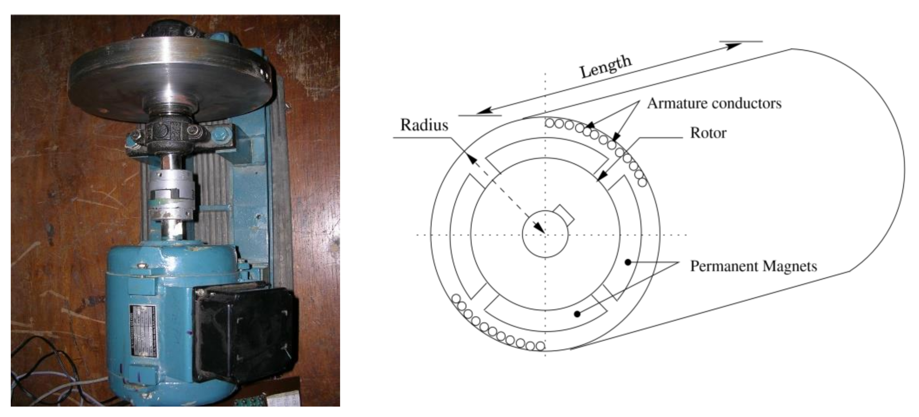
- Permanent magnet synchronous machine (PMSM)
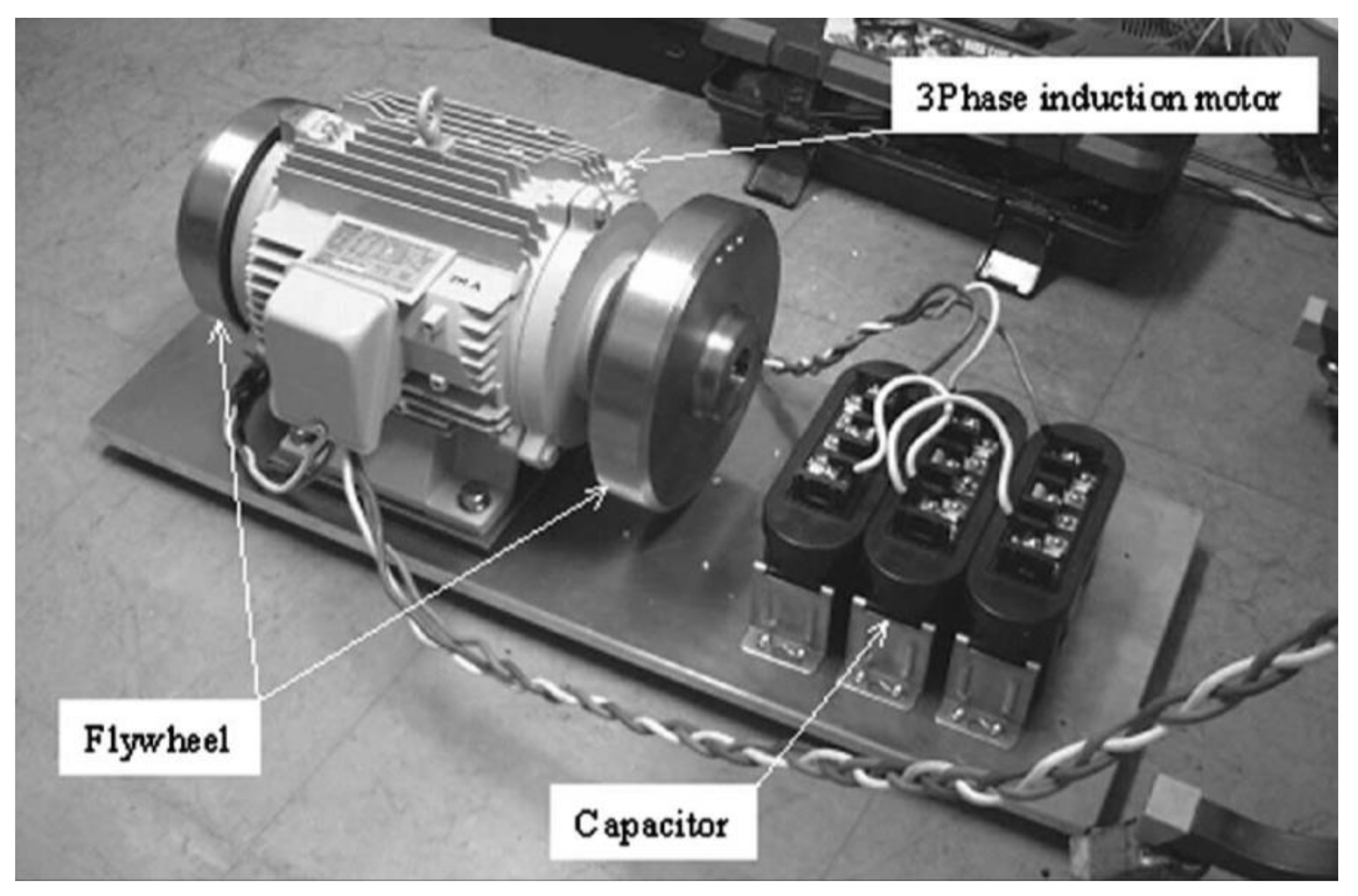
- Induction Machine (IM)
- ○
- The induction machine shown in Figure 5 should be considered the best all-round choice for high-power installations [73]. They are stoutly constructed, with low build cost, they suit high torque applications, and they are highly reliable [67,74]. They do not suit high-speed applications [75], although double-fed induction machines (DFIM) are in development to overcome this limitation [76,77].
- Brushless direct current machine (BLDCM)
- ○
- A BLDCM as shown in Figure 6 is designed to be a synchronous machine containing a permanent magnet within the rotor and operates a self-controlling function, optimising the stator current by the use of an inverter. High efficiency, large operational speed range, compactness, mechanical stablility, low maintenance, and operation without electromagnetic interference are the main advantages of a brushless direct current machine [78,79,80,81,82,83].
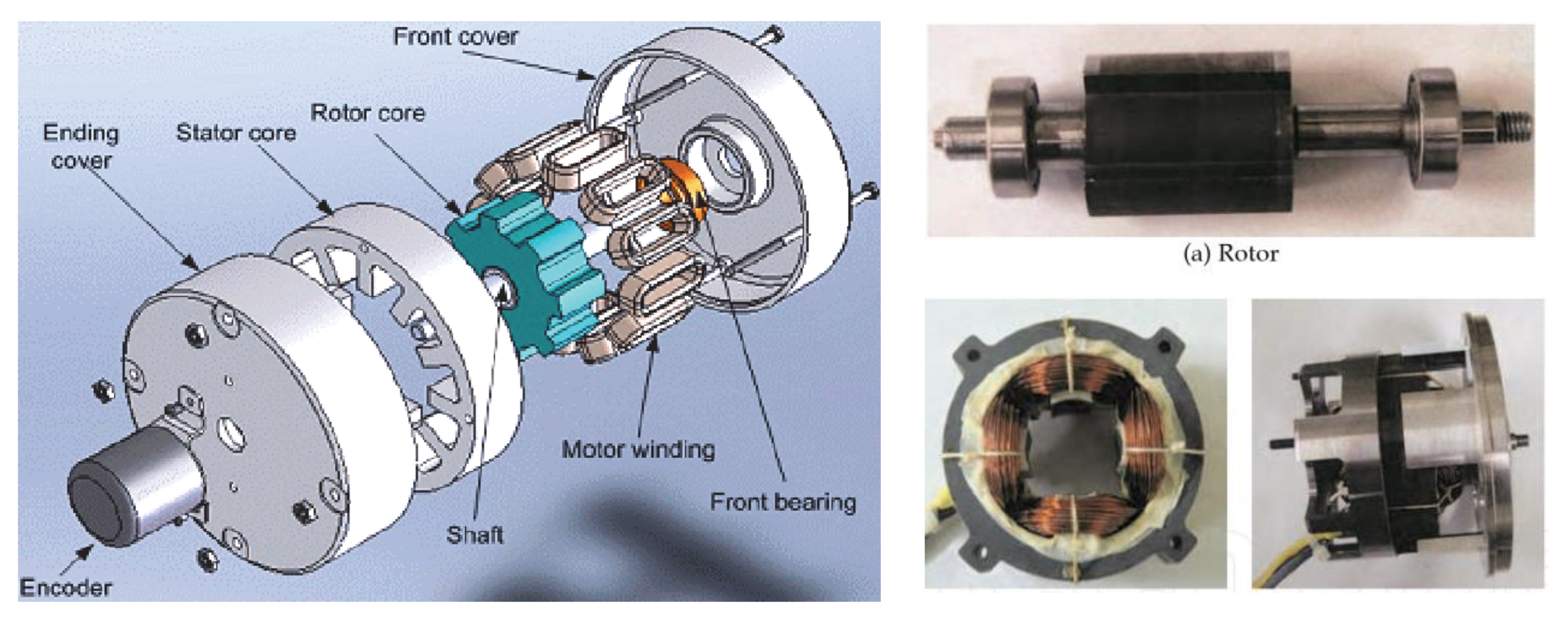
- Switched reluctance machine (SRM)
- ○
- The switched reluctance machine shown in Figure 7 with it’s rotor (7(a)) below has a simplified build, and idle losses are low. They can operate in harsh environments, including at temperatures of 400 °C, still with a wide speed range [84]. Switched reluctance machines similarly are operational even when one or two phases are damaged. An SRM is challenging to control at lower speeds but is easier to control at high speeds than an induction machine [85].
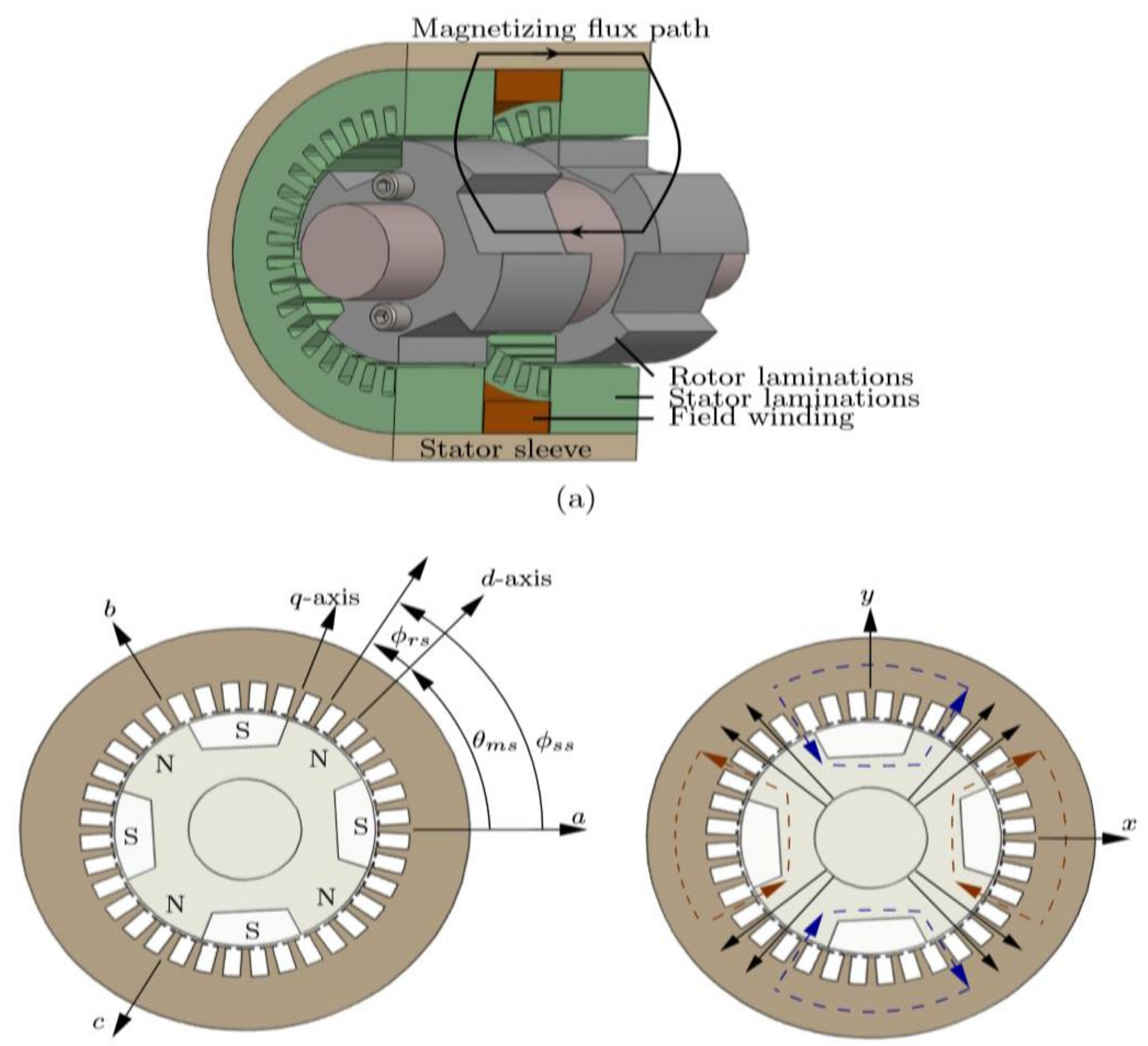
- Homopolar machine (HM)
- ○
- The HM shown in Figure 8 is also known as the homopolar inductor alternator and also the homopolar synchronous machine [86]. The homopolar machine is well built with low idle losses and suits long-term high-speed applications due to its reliability [87]. There is a reduction in the self-discharge rate using this technology, hence increasing efficiency as well as energy density [88]. This, therefore, reduces the overall cost of this technology. This motor utilises a single winding to generate torque in the absence of permanent magnets [89,90]. They are also ideal for industrial blowers, hole pumps, etc. [91]. Current excitation on the stator side for this type of machine is used with a flywheel [92,93]. During the idling period, magnetisation can be eliminated through the turning down of the current, hence reducing self-discharge losses.
- Synchronous Reluctance Machine (SRM)
- ○
- An SRM depicted in Figure 9 is capable of controlling varying torques via two thyristor-controlled components coupled to the stator windings. This allows a dampening effect in the rotating components when used in oscillation mode [95]. Table 4 compares the differences between the switched reluctance machine and synchronous reluctance machine.
2.2. Rotor Bearing
- Permanent (Passive) magnetic bearing (PMB).
- ○
- PMBs are permanent magnets (Figure 10) rather than electromagnetic so therefore are used with other bearing types as they are unable to sufficiently dampen movement on all axes [104]. PMBs offer extremely low losses because of the absence of electromagnetic drag and have low construction and installation costs. They are also used as auxiliary bearings as required [105,106].
- Active magnetic bearing (AMB)
- ○
- Active magnetic bearing (Figure 11) accommodates coils that can adjust the amount of electromagnetic force in the system, thereby reducing vibrations in the rotating mass [108,109]. This is achieved via a feedback system monitoring the shaft position and increasing the stability of the FESS. This suspension and stiffness control increase losses from the power output due to the presence of the control system current. When used in conjunction with mechanical bearings, the complications of the control system can be reduced, making this option more cost-effective, stable, and feasible. However, there is still a need for a complex control system and, therefore, this should not be considered in applications susceptible to electromagnetic interference [110].
- Superconducting magnetic bearing (SMB).
- ○
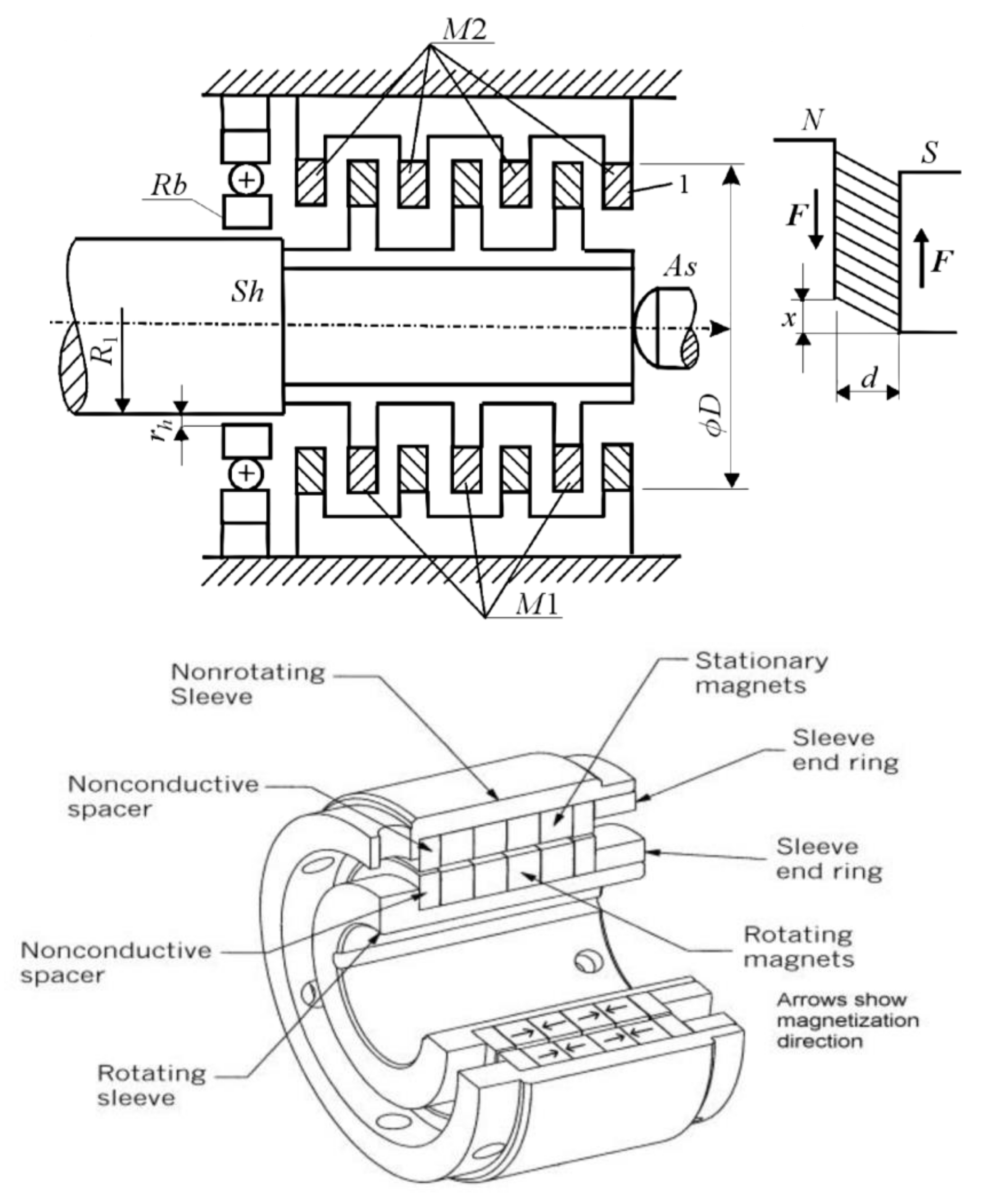
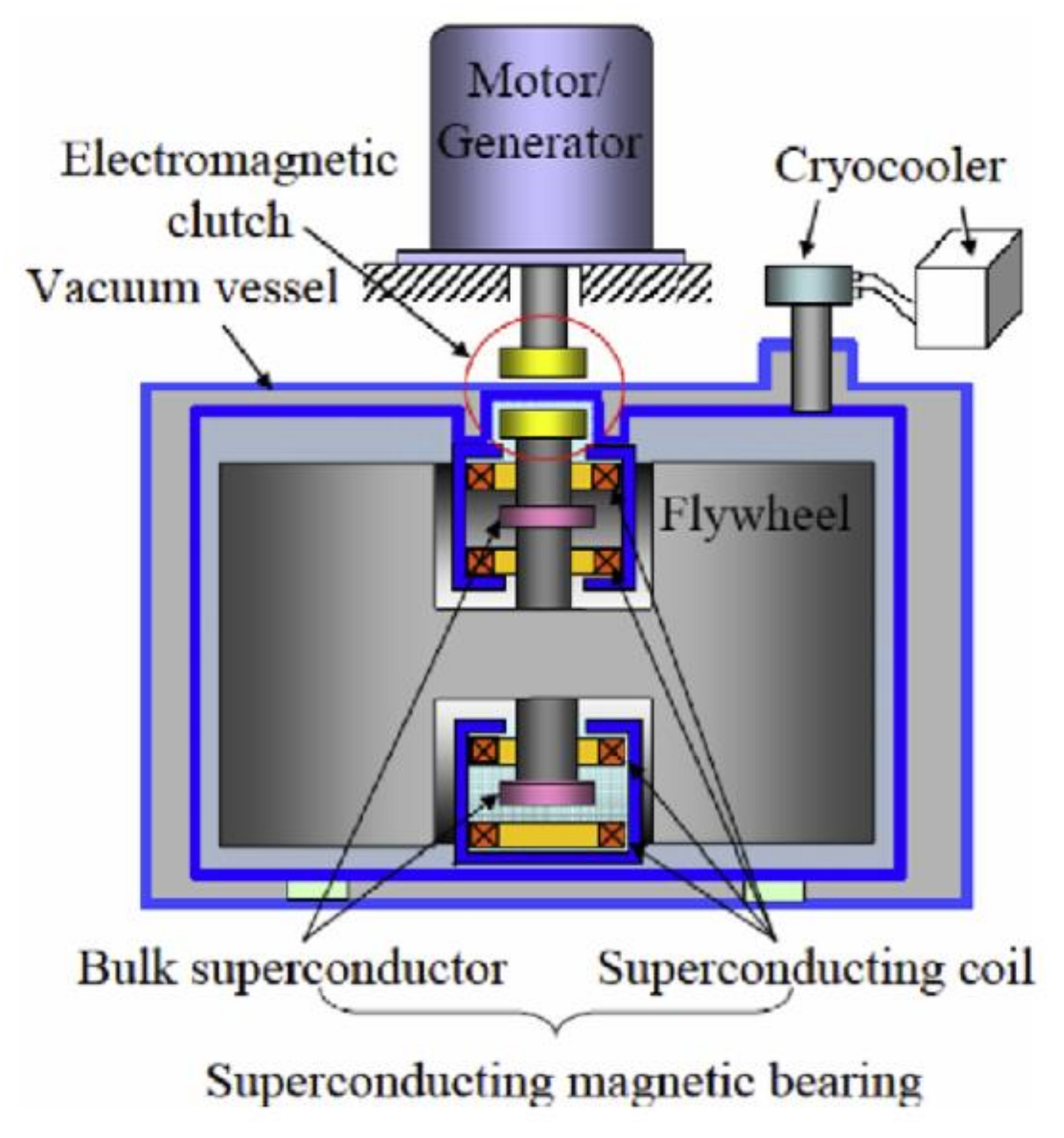
- SMBs are best for high-speed use, as shown in Figure 12 below. The high speeds generated and the comparatively friction-free environment offer long life and stability. The main disadvantage with SMBs is the need for very low operating temperatures. Cryogenic cooling is needed to keep the bearings from failing. High-temperature superconductors (HTS) are in use with SMBs to combat this system requirement, and there have been recent attempts to incorporate cryogenic isolation for the SMBs to reduce costs and keep the operating temperatures low, but, at the moment, SMBs and PMBs need to be used at the same time [111,112].
- Bearingless machine (BM)
- ○
- A bearingless machine is capable of combining the two independent operations of magnetic suspension and generating torque into a single machine. This approach can be applied to the other types of machine mentioned herein, offering a reduced cost and compact design. BM can be implemented in high-speed FESS [122].
2.3. Containment/Housing
2.4. Power Electronic Interface
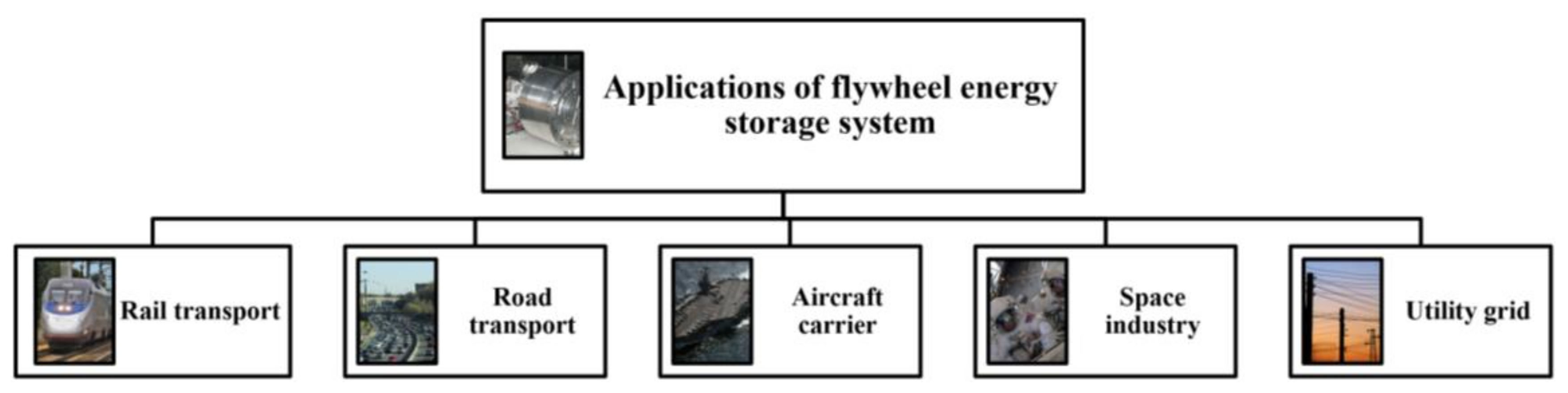
3. Current Application of FESS
3.1. Application of Flywheel in the Transport Sector
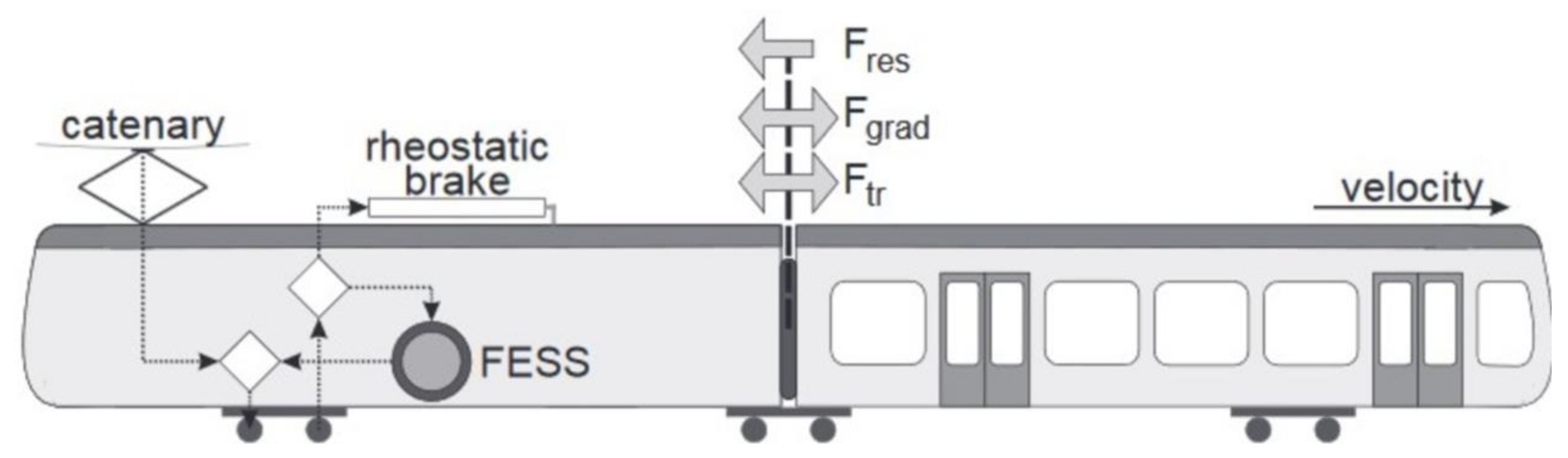
3.1.1. Rail Transport
- On-board use in diesel–electric vehicles to store braking energy;
- On-board use in DC systems to raise the recuperation rate;
- Stationary use in DC power supply systems to raise the recuperation rate.
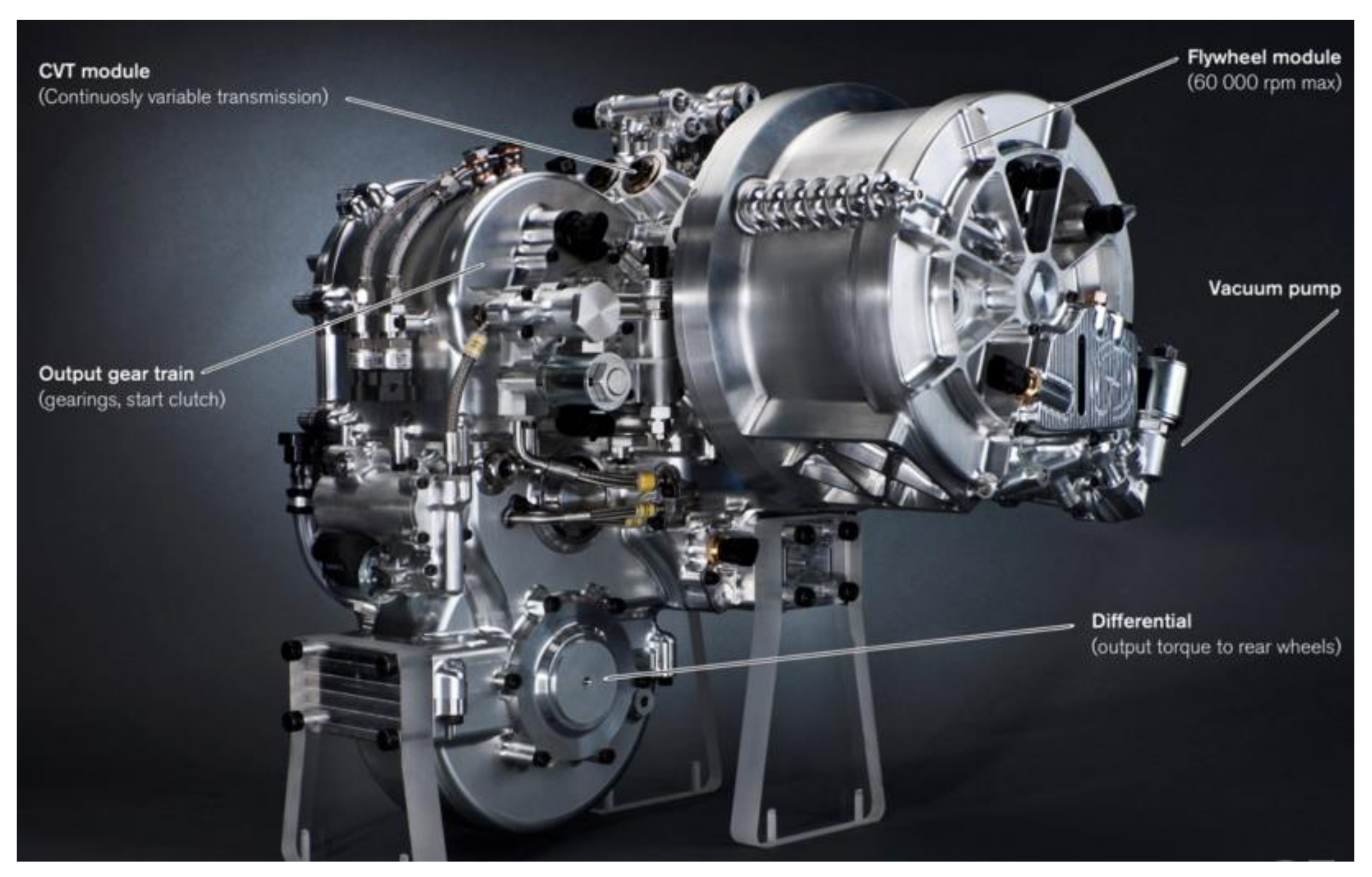
3.1.2. Road Transport
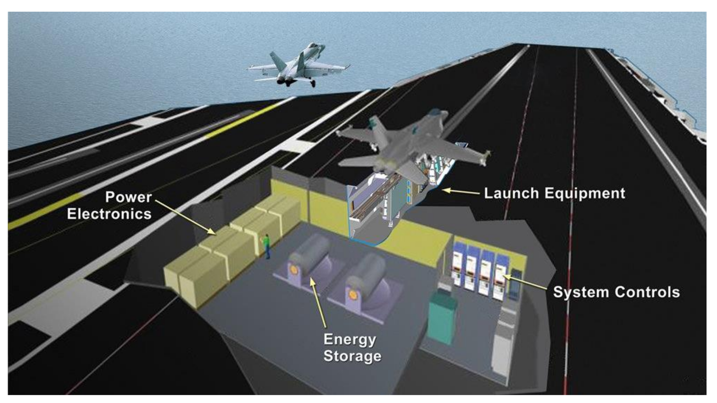
3.2. Aircraft Carrier
3.2.1. Incredible Hulk Roller Coaster
3.2.2. Domestic Applications of Flywheels
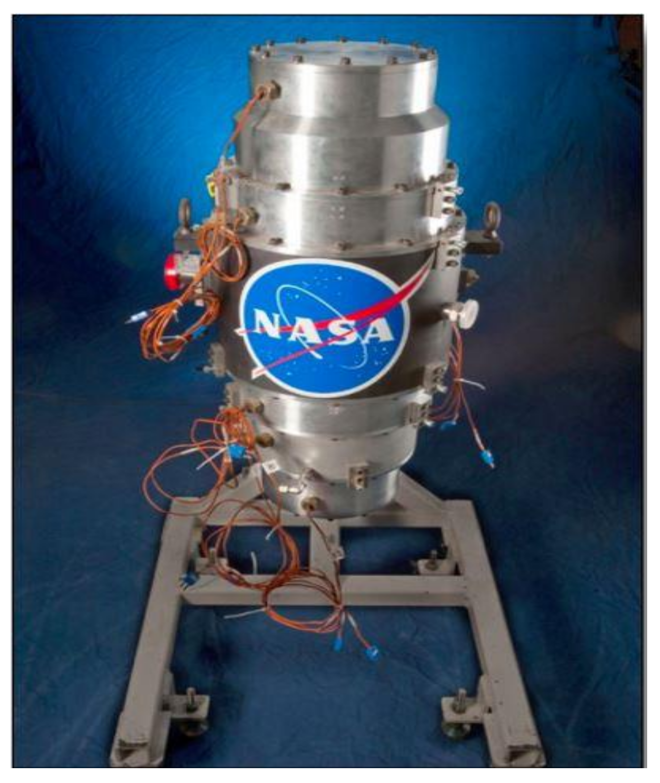
3.2.3. Flywheel Application in the Space Industry
3.3. Load Levellers
3.4. Emergency Devices
3.5. Low-Energy Applications
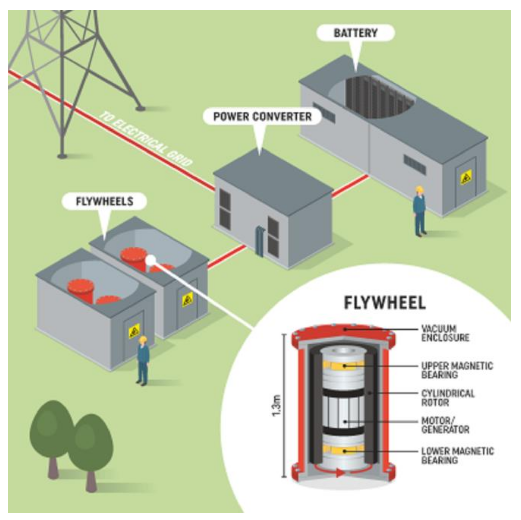
3.6. Utility Grid
3.7. Materials
- The flywheel stores kinetic energy E
- 2.
- J = πρR4t/2 axial mass moment of inertia of the disc and ρ is density; therefore,
- 3.
- Energy per unit of mass is the ratio of the last two equations
- 4.
- Poisson’s ratio, v. Stress must not exceed yield strength (σy), factor of safety, S.
- 5.
- v is roughly 1/3 for solids and is treated as a constant
Commercial Use
4. Design
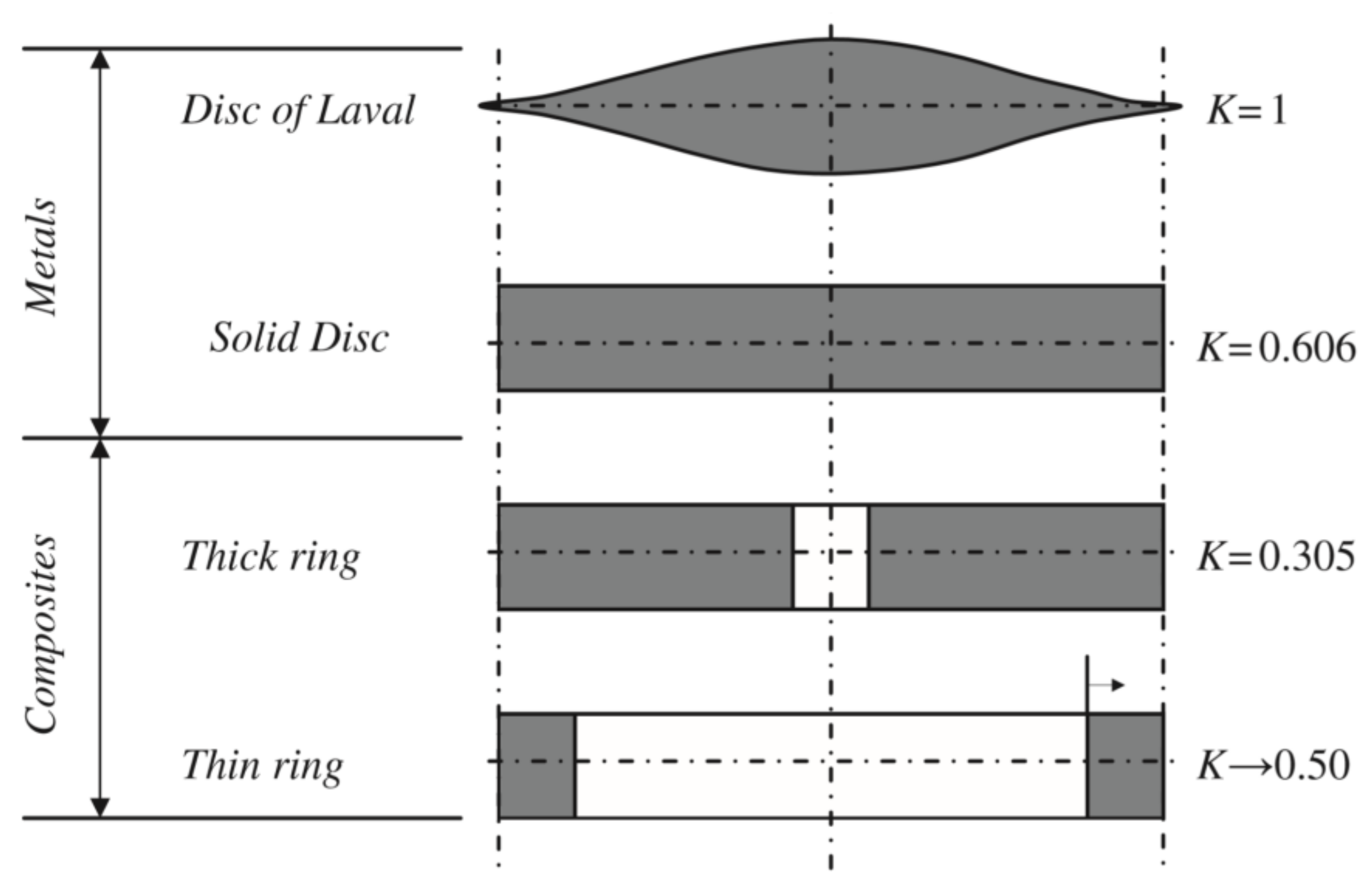
4.1. Rotor Design
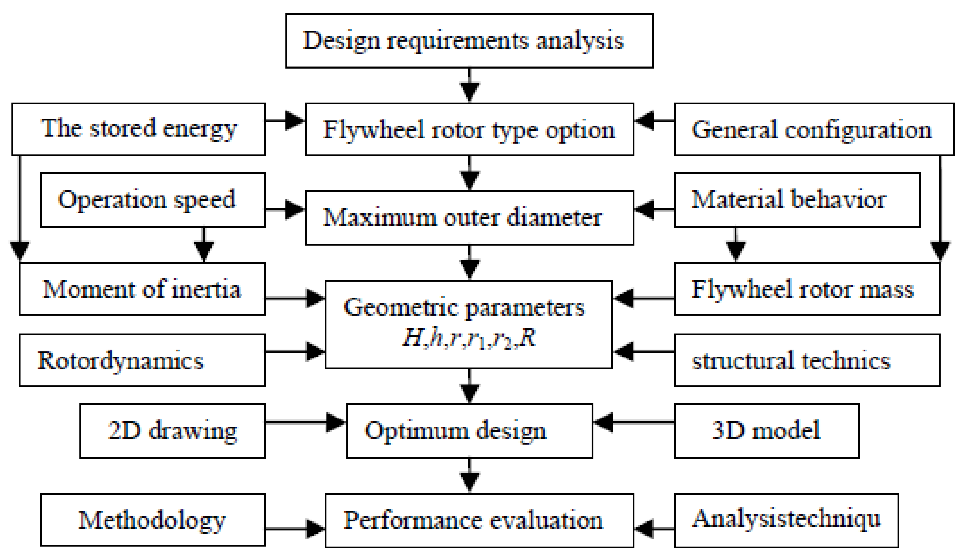
4.2. The Flywheel Rotor Design Process
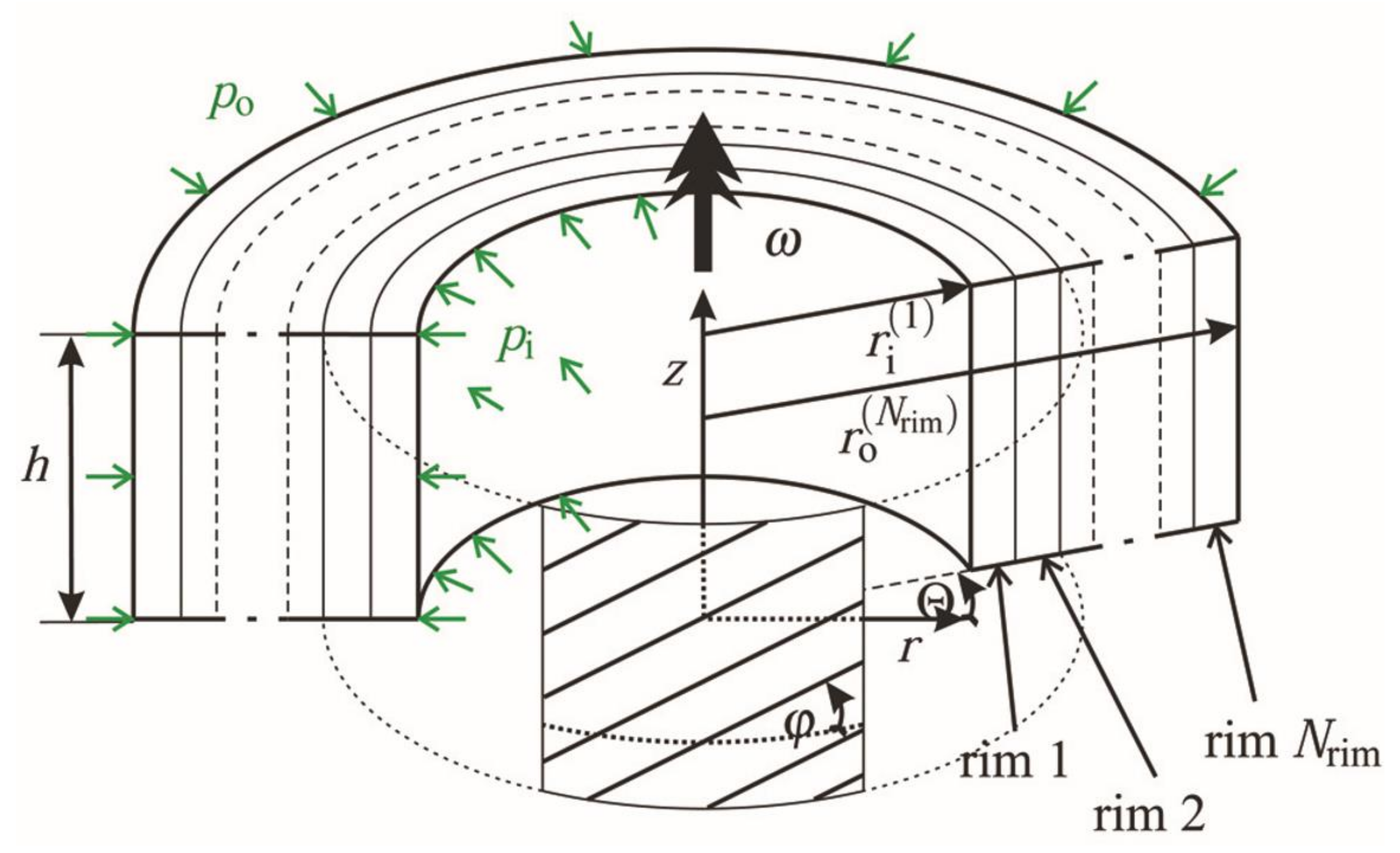
4.3. The Stress Analysis
4.4. The Failure Criteria Selection
4.5. Overview of Flywheel Mounted on a Rotating System
4.5.1. Bearing Load
Shock
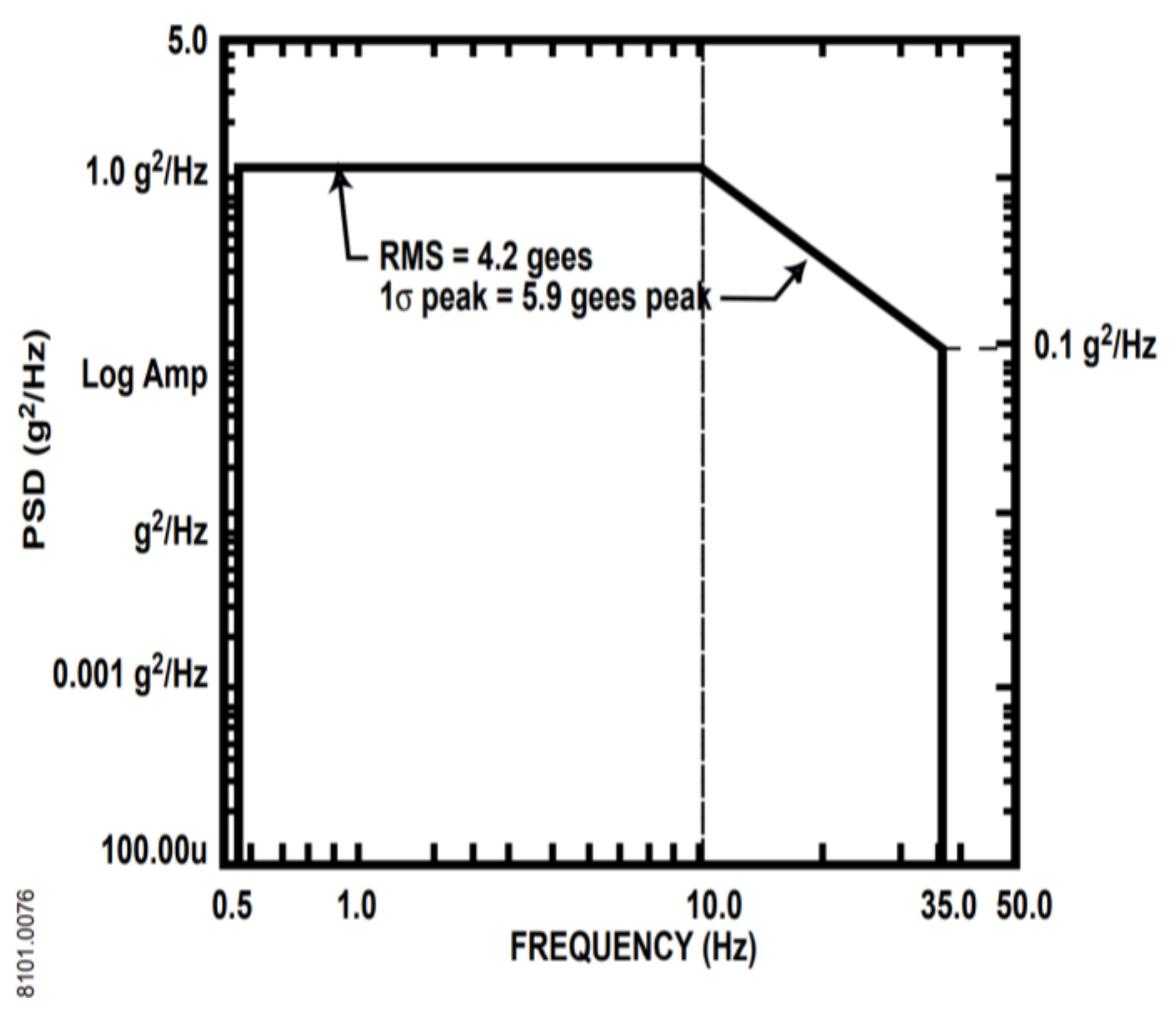
Vibrations
Rotating Mass Imbalance
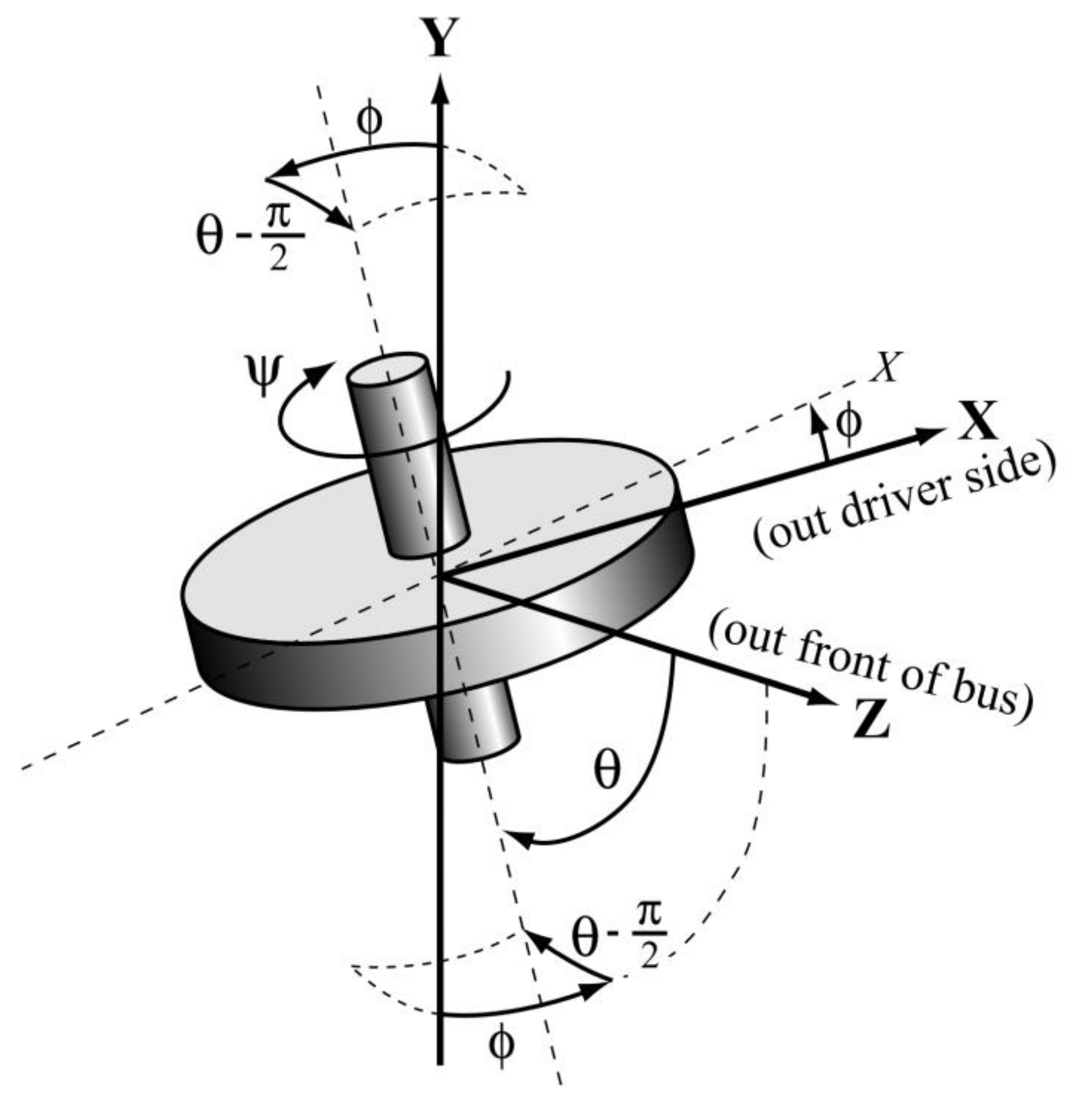
Gyrodynamics
- (i)
- The vehicle turn in-plane, provided that the flywheel is not in its home orientation in relation to the vehicle;
- (ii)
- Vehicle pitch or roll, subject to whether the flywheel energy storage support uses a spring or damper bolted to the car frame;
- (iii)
- Vehicle lateral acceleration, provided that the support uses a pendulum-type spring;
- (iv)
- Torque on the flywheel energy storage emanating from the flywheel energy storage system motor-generator, provided that the stator’s reaction torque vector comes with an element normal to the spin axes of the flywheel;
- (v)
- Torque on the flywheel energy storage systems rotor obtained using bearings, but the beating’s stator reaction torque vectors must be normal to the spin axis.
5. Future Development of FESS
5.1. Application of Flywheel Energy Storage Systems in Renewable Energy Sources
5.2. Application of Flywheel Energy Storage Systems in Military
5.3. Application of Flywheel Energy Storage Systems in Spacecraft
6. Conclusions
Author Contributions
Funding
Institutional Review Board Statement
Informed Consent Statement
Data Availability Statement
Conflicts of Interest
References
- Elsaid, K.; Kamil, M.; Sayed, E.T.; Abdelkareem, M.A.; Wilberforce, T.; Olabi, A. Environmental impact of desalination technologies: A review. Sci. Total. Environ. 2020, 748, 141528. [Google Scholar] [CrossRef]
- Shehata, N.; Sayed, E.T.; Abdelkareem, M.A. Recent progress in environmentally friendly geopolymers: A review. Sci. Total. Environ. 2021, 762, 143166. [Google Scholar] [CrossRef] [PubMed]
- Zhang, Z.; Zhang, Y.; Sui, X.; Li, W.; Xu, D. Performance of Thermoelectric Power-Generation System for Sufficient Recovery and Reuse of Heat Accumulated at Cold Side of TEG with Water-Cooling Energy Exchange Circuit. Energies 2020, 13, 5542. [Google Scholar] [CrossRef]
- Olabi, A.; Elsaid, K.; Rabaia, M.K.H.; Askalany, A.A.; Abdelkareem, M.A. Waste heat-driven desalination systems: Perspective. Energy 2020, 209, 118373. [Google Scholar] [CrossRef]
- Olabi, A.; Wilberforce, T.; Abdelkareem, M.A. Fuel cell application in the automotive industry and future perspective. Energy 2021, 214, 118955. [Google Scholar] [CrossRef]
- Olabi, A.; Wilberforce, T.; Sayed, E.T.; Elsaid, K.; Abdelkareem, M.A. Prospects of Fuel Cell Combined Heat and Power Systems. Energies 2020, 13, 4104. [Google Scholar] [CrossRef]
- Abdelkareem, M.A.; Elsaid, K.; Wilberforce, T.; Kamil, M.; Sayed, E.T.; Olabi, A. Environmental aspects of fuel cells: A review. Sci. Total. Environ. 2021, 752, 141803. [Google Scholar] [CrossRef]
- Moriarty, P.; Honnery, D. Feasibility of a 100% Global Renewable Energy System. Energies 2020, 13, 5543. [Google Scholar] [CrossRef]
- Gumbarević, S.; Burcar Dunović, I.; Milovanović, B.; Gaši, M. Method for Building Information Modeling Supported Project Control of Nearly Zero-Energy Building Delivery. Energies 2020, 13, 5519. [Google Scholar] [CrossRef]
- Sefidari, H.; Lindblom, B.; Nordin, L.-O.; Wiinikka, H. The Feasibility of Replacing Coal with Biomass in Iron-Ore Pelletizing Plants with Respect to Melt-Induced Slagging. Energies 2020, 13, 5386. [Google Scholar] [CrossRef]
- Wilberforce, T.; Baroutaji, A.; Soudan, B.; Al-Alami, A.H.; Olabi, A.G. Outlook of carbon capture technology and challenges. Sci. Total. Environ. 2019, 657, 56–72. [Google Scholar] [CrossRef]
- Abdelkareem, M.A.; Lootah, M.A.; Sayed, E.T.; Wilberforce, T.; Alawadhi, H.; Yousef, B.A.; Olabi, A. Fuel cells for carbon capture applications. Sci. Total. Environ. 2021, 769, 144243. [Google Scholar] [CrossRef] [PubMed]
- Wilberforce, T.; Olabi, A.; Sayed, E.T.; Elsaid, K.; Abdelkareem, M.A. Progress in carbon capture technologies. Sci. Total. Environ. 2021, 761, 143203. [Google Scholar] [CrossRef] [PubMed]
- Olabi, A.; Abdelkareem, M. Energy storage systems towards 2050. Energy 2021, 219, 119634. [Google Scholar] [CrossRef]
- Olabi, A.; Abdelkareem, M.A.; Wilberforce, T.; Sayed, E.T. Application of graphene in energy storage device—A review. Renew. Sustain. Energy Rev. 2021, 135, 110026. [Google Scholar] [CrossRef]
- Sayed, E.T.; Abdelkareem, M.A.; Alawadhi, H.; Salameh, T.; Olabi, A.; Alami, A.H. Facile and low-cost synthesis route for graphene deposition over cobalt dendrites for direct methanol fuel cell applications. J. Taiwan Inst. Chem. Eng. 2020, 115, 321–330. [Google Scholar] [CrossRef]
- Abdelkareem, M.A.; Wilberforce, T.; Elsaid, K.; Sayed, E.T.; Abdelghani, E.A.; Olabi, A. Transition metal carbides and nitrides as oxygen reduction reaction catalyst or catalyst support in proton exchange membrane fuel cells (PEMFCs). Int. J. Hydrogen Energy 2020. [Google Scholar] [CrossRef]
- Liu, S.; Li, W.; Zheng, G.; Yang, H.; Li, L. Optimization of Cattle Manure and Food Waste Co-Digestion for Biohydrogen Production in a Mesophilic Semi-Continuous Process. Energies 2020, 13, 3848. [Google Scholar] [CrossRef]
- Abdelkareem, M.A.; Tanveer, W.H.; Sayed, E.T.; Assad, M.E.H.; Allagui, A.; Cha, S. On the technical challenges affecting the performance of direct internal reforming biogas solid oxide fuel cells. Renew. Sustain. Energy Rev. 2019, 101, 361–375. [Google Scholar] [CrossRef]
- Wilberforce, T.; Sayed, E.T.; Abdelkareem, M.A.; Elsaid, K.; Olabi, A.G. Value added products from wastewater using bioelectrochemical systems: Current trends and perspectives. J. Water Process Eng. 2020, 39, 101737. [Google Scholar] [CrossRef]
- Sayed, E.; Alawadhi, H.; Elsaid, K.; Olabi, A.; Almakrani, M.A.; Bin Tamim, S.; Alafranji, G.; Abdelkareem, M. A Carbon-Cloth Anode Electroplated with Iron Nanostructure for Microbial Fuel Cell Operated with Real Wastewater. Sustainability 2020, 12, 6538. [Google Scholar] [CrossRef]
- Salameh, T.; Abdelkareem, M.A.; Olabi, A.; Sayed, E.T.; Al-Chaderchi, M.; Rezk, H. Integrated standalone hybrid solar PV, fuel cell and diesel generator power system for battery or supercapacitor storage systems in Khorfakkan, United Arab Emirates. Int. J. Hydrogen Energy 2021, 46, 6014–6027. [Google Scholar] [CrossRef]
- Rezk, H.; Sayed, E.T.; Al-Dhaifallah, M.; Obaid, M.; El-Sayed, A.H.M.; Abdelkareem, M.A.; Olabi, A. Fuel cell as an effective energy storage in reverse osmosis desalination plant powered by photovoltaic system. Energy 2019, 175, 423–433. [Google Scholar] [CrossRef]
- Olabi, A.G.; Onumaegbu, C.; Wilberforce, T.; Ramadan, M.; Abdelkareem, M.A.; Al-Alami, A.H. Critical Review of Energy Storage Systems. Energy 2020, 118987. [Google Scholar] [CrossRef]
- Khzouz, M.; Gkanas, E.I.; Shao, J.; Sher, F.; Beherskyi, D.; El-Kharouf, A.; Al Qubeissi, M. Life Cycle Costing Analysis: Tools and Applications for Determining Hydrogen Production Cost for Fuel Cell Vehicle Technology. Energies 2020, 13, 3783. [Google Scholar] [CrossRef]
- Wilberforce, T.; El-Hassan, Z.; Khatib, F.; Al Makky, A.; Baroutaji, A.; Carton, J.G.; Olabi, A.G. Developments of electric cars and fuel cell hydrogen electric cars. Int. J. Hydrogen Energy 2017, 42, 25695–25734. [Google Scholar] [CrossRef]
- Baroutaji, A.; Wilberforce, T.; Ramadan, M.; Olabi, A.G. Comprehensive investigation on hydrogen and fuel cell technology in the aviation and aerospace sectors. Renew. Sustain. Energy Rev. 2019, 106, 31–40. [Google Scholar] [CrossRef]
- Wilberforce, T.; Alaswad, A.; Palumbo, A.; Dassisti, M.; Olabi, A. Advances in stationary and portable fuel cell applications. Int. J. Hydrogen Energy 2016, 41, 16509–16522. [Google Scholar] [CrossRef]
- Mahmoud, M.; Ramadan, M.; Olabi, A.-G.; Pullen, K.; Naher, S. A review of mechanical energy storage systems combined with wind and solar applications. Energy Convers. Manag. 2020, 210, 112670. [Google Scholar] [CrossRef]
- Bolund, B.; Bernhoff, H.; Leijon, M. Flywheel energy and power storage systems. Renew. Sustain. Energy Rev. 2007, 11, 235–258. [Google Scholar] [CrossRef]
- Wicki, S.; Hansen, E.G. Clean energy storage technology in the making: An innovation systems perspective on flywheel energy storage. J. Clean. Prod. 2017, 162, 1118–1134. [Google Scholar] [CrossRef] [PubMed]
- Strzelecki, R.M. Power Electronics in Smart Electrical Energy Networks; Springer Science & Business Media: Berlin/Heidelberg, Germany, 2008. [Google Scholar]
- Barelli, L.; Bidini, G.; Bonucci, F.; Castellini, L.; Fratini, A.; Gallorini, F.; Zuccari, A. Flywheel hybridization to improve battery life in energy storage systems coupled to RES plants. Energy 2019, 173, 937–950. [Google Scholar] [CrossRef]
- Kondoh, J.; Funamoto, T.; Nakanishi, T.; Arai, R. Energy characteristics of a fixed-speed flywheel energy storage system with direct grid-connection. Energy 2018, 165, 701–708. [Google Scholar] [CrossRef]
- Rupp, A.; Baier, H.; Mertiny, P.; Secanell, M. Analysis of a flywheel energy storage system for light rail transit. Energy 2016, 107, 625–638. [Google Scholar] [CrossRef]
- Zhao, P.; Wang, M.; Wang, J.; Dai, Y. A preliminary dynamic behaviors analysis of a hybrid energy storage system based on adiabatic compressed air energy storage and flywheel energy storage system for wind power application. Energy 2015, 84, 825–839. [Google Scholar] [CrossRef]
- Suzuki, Y.; Koyanagi, A.; Kobayashi, M.; Shimada, R. Novel applications of the flywheel energy storage system. Energy 2005, 30, 2128–2143. [Google Scholar] [CrossRef]
- Boukettaya, G.; Krichen, L.; Ouali, A. A comparative study of three different sensorless vector control strategies for a Flywheel Energy Storage System. Energy 2010, 35, 132–139. [Google Scholar] [CrossRef]
- Okou, R.; Sebitosi, A.; Pillay, P. Flywheel rotor manufacture for rural energy storage in sub-Saharan Africa. Energy 2011, 36, 6138–6145. [Google Scholar] [CrossRef]
- Olabi, A. Renewable Energy and Energy Storage Systems; Elsevier: Amsterdam, The Netherlands, 2017. [Google Scholar]
- Boukettaya, G.; Krichen, L. A dynamic power management strategy of a grid connected hybrid generation system using wind, photovoltaic and Flywheel Energy Storage System in residential applications. Energy 2014, 71, 148–159. [Google Scholar] [CrossRef]
- Huang, C.-N.; Chen, Y.-S. Design of magnetic flywheel control for performance improvement of fuel cells used in vehicles. Energy 2017, 118, 840–852. [Google Scholar] [CrossRef]
- Ferreira, H.L.; Garde, R.; Fulli, G.; Kling, W.; Lopes, J.P. Characterisation of electrical energy storage technologies. Energy 2013, 53, 288–298. [Google Scholar] [CrossRef]
- Pena-Alzola, R.; Sebastián, R.; Quesada, J.; Colmenar, A. Review of Flywheel Based Energy Storage Systems. In Proceedings of the 2011 International Conference on Power Engineering, Energy and Electrical Drives, Malaga, Spain, 11–13 May 2011; IEEE: Piscataway, NJ, USA, 2011; pp. 1–6. [Google Scholar]
- McMahon, R.; Infante, L. Energy Storage in the United States. In Renewable Energy Integration; Elsevier: Amsterdam, The Netherlands, 2017; pp. 281–292. [Google Scholar]
- Bitterly, J.G. Flywheel technology: Past, present, and 21st century projections. IEEE Aerosp. Electron. Syst. Mag. 1998, 13, 13–16. [Google Scholar] [CrossRef]
- Pullen, K.R. The Status and Future of Flywheel Energy Storage. Joule 2019, 3, 1394–1399. [Google Scholar] [CrossRef]
- Mousavi, G.S.M.; Faraji, F.; Majazi, A.; Al-Haddad, K. A comprehensive review of Flywheel Energy Storage System technology. Renew. Sustain. Energy Rev. 2017, 67, 477–490. [Google Scholar] [CrossRef]
- Wang, Y.; Wang, C.; Xue, H. A novel capacity configuration method of flywheel energy storage system in electric vehicles fast charging station. Electric Power Syst. Res. 2021, 195, 107185. [Google Scholar] [CrossRef]
- Goris, F.; Severson, E.L. A Review of Flywheel Energy Storage Systems for Grid Application. In Proceedings of the IECON 2018—44th Annual Conference of the IEEE Industrial Electronics Society, Washington, DC, USA, 21–23 October 2018; pp. 1633–1639. [Google Scholar]
- Amiryar, M.E.; Pullen, K.R. A Review of Flywheel Energy Storage System Technologies and Their Applications. Appl. Sci. 2017, 7, 286. [Google Scholar] [CrossRef]
- Kousksou, T.; Bruel, P.; Jamil, A.; El Rhafiki, T.; Zeraouli, Y. Energy storage: Applications and challenges. Sol. Energy Mater. Sol. Cells 2014, 120, 59–80. [Google Scholar] [CrossRef]
- Zakeri, B.; Syri, S. Electrical energy storage systems: A comparative life cycle cost analysis. Renew. Sustain. Energy Rev. 2015, 42, 569–596. [Google Scholar] [CrossRef]
- Dhand, A.; Pullen, K. Review of flywheel based internal combustion engine hybrid vehicles. Int. J. Automot. Technol. 2013, 14, 797–804. [Google Scholar] [CrossRef]
- Doucette, R.T.; McCulloch, M.D. A comparison of high-speed flywheels, batteries, and ultracapacitors on the bases of cost and fuel economy as the energy storage system in a fuel cell based hybrid electric vehicle. J. Power Sources 2011, 196, 1163–1170. [Google Scholar] [CrossRef]
- Gabrys, C.W. High Performance Composite Flywheel. U.S. Patent US6583528B2, 24 June 2003. [Google Scholar]
- Liu, H.; Jiang, J. Flywheel energy storage—An upswing technology for energy sustainability. Energy Build. 2007, 39, 599–604. [Google Scholar] [CrossRef]
- Sotelo, G.; De Andrade, R.; Ferreira, A. Magnetic Bearing Sets for a Flywheel System. IEEE Trans. Appl. Supercond. 2007, 17, 2150–2153. [Google Scholar] [CrossRef]
- Werfel, F.; Floegel-Delor, U.; Rothfeld, R.; Riedel, T.; Goebel, B.; Wippich, D.; Schirrmeister, P. Superconductor bearings, flywheels and transportation. Supercond. Sci. Technol. 2011, 25, 014007. [Google Scholar] [CrossRef]
- Ren, M.; Shen, Y.; Li, Z.; Nonami, K. Modeling and control of a flywheel energy storage system using active magnetic bearing for vehicle. In Proceedings of the IEEE 2009 International Conference on Information Engineering and Computer Science, Wuhan, China, 19–20 December 2009; pp. 1–5. [Google Scholar]
- Karrari, S.; Noe, M.; Geisbuesch, J. High-speed Flywheel Energy Storage System (FESS) for Voltage and Frequency Support in Low Voltage Distribution Networks. In Proceedings of the 2018 IEEE 3rd International Conference on Intelligent Energy and Power Systems (IEPS), Kyiv, Ukraine, 10–14 September 2018; pp. 176–182. [Google Scholar]
- Daoud, M.I.; Abdel-Khalik, A.S.; Massoud, A.; Ahmed, S.; Abbasy, N.H. On the development of flywheel storage systems for power system applications: A survey. In Proceedings of the 2012 XXth International Conference on Electrical Machines, Marseille, France, 2–5 September 2012; pp. 2119–2125. [Google Scholar]
- Bianchini, C.; Torreggiani, A.; David, D.; Bellini, A. Design of motor/generator for Flywheel Batteries. IEEE Trans. Ind. Electron. 2020, 1. [Google Scholar] [CrossRef]
- May, G.J.; Davidson, A.; Monahov, B. Lead batteries for utility energy storage: A review. J. Energy Storage 2018, 15, 145–157. [Google Scholar] [CrossRef]
- Gerada, D.; Mebarki, A.; Brown, N.L.; Gerada, C.; Cavagnino, A.; Boglietti, A. High-Speed Electrical Machines: Technologies, Trends, and Developments. IEEE Trans. Ind. Electron. 2014, 61, 2946–2959. [Google Scholar] [CrossRef]
- Chao, W.; Xingjian, D.; Yong, W.; Xi, L.; Guobin, Z. Research progress of energy storage composite flywheel. Energy Storage Sci. Technol. 2017, 6, 1076. [Google Scholar]
- Cansiz, A.; Yildizer, I.; Oral, E.A.; Kaya, Y. An Effective Noncontact Torque Mechanism and Design Considerations for an Evershed-Type Superconducting Magnetic Bearing System. IEEE Trans. Appl. Supercond. 2013, 24, 22–29. [Google Scholar] [CrossRef]
- Kale, V.; Secanell, M. A comparative study between optimal metal and composite rotors for flywheel energy storage systems. Energy Rep. 2018, 4, 576–585. [Google Scholar] [CrossRef]
- Lee, H.; Shin, B.Y.; Han, S.; Jung, S.; Park, B.; Jang, G. Compensation for the Power Fluctuation of the Large Scale Wind Farm Using Hybrid Energy Storage Applications. IEEE Trans. Appl. Supercond. 2011, 22, 5701904. [Google Scholar] [CrossRef]
- Suvire, G.O.; Molina, M.G.; Mercado, P.E. Improving the Integration of Wind Power Generation Into AC Microgrids Using Flywheel Energy Storage. IEEE Trans. Smart Grid 2012, 3, 1945–1954. [Google Scholar] [CrossRef]
- Abrahamsson, J.; Hedlund, M.; Kamf, T.; Bernhoff, H. High-Speed Kinetic Energy Buffer: Optimization of Composite Shell and Magnetic Bearings. IEEE Trans. Ind. Electron. 2013, 61, 3012–3021. [Google Scholar] [CrossRef]
- Bernard, N.; Ahmed, H.B.; Multon, B. Semi-analytical inductance calculation on an axial-field synchronous machine for a flywheel storage system using surfacic permeances. In Proceedings of the IEMDC 2001. IEEE International Electric Machines and Drives Conference (Cat. No. 01EX485), Cambridge, MA, USA, 17–20 June 2001; pp. 382–390. [Google Scholar]
- Abdel-Khalik, A.S.; Elserougi, A.A.; Massoud, A.M.; Ahmed, S. Fault Current Contribution of Medium Voltage Inverter and Doubly-Fed Induction-Machine-Based Flywheel Energy Storage System. IEEE Trans. Sustain. Energy 2012, 4, 58–67. [Google Scholar] [CrossRef]
- Wang, L.; Yu, J.-Y.; Chen, Y.-T. Dynamic stability improvement of an integrated offshore wind and marine-current farm using a flywheel energy-storage system. IET Renew. Power Gener. 2011, 5, 387–396. [Google Scholar] [CrossRef]
- Sun, X.-D.; Koh, K.-H.; Yu, B.-G.; Matsui, M. Fuzzy-logic-based $ V/f $ control of an induction motor for a DC grid power-leveling system using flywheel energy storage equipment. IEEE Trans. Ind. Electron. 2009, 56, 3161–3168. [Google Scholar]
- Wu, J.; Wen, J.; Sun, H. A new energy storage system based on flywheel. In Proceedings of the 2009 IEEE Power & Energy Society General Meeting, Calgary, AB, Canada, 26–30 July 2009; pp. 1–6. [Google Scholar]
- Ran, L.; Xiang, D.; Kirtley, J.L. Analysis of Electromechanical Interactions in a Flywheel System with a Doubly Fed Induction Machine. 2010 IEEE Ind. Appl. Soc. Annu. Meet. 2010, 47, 1–8. [Google Scholar] [CrossRef]
- Liu, G.; Zhang, C. Sliding mode control of reaction flywheel-based brushless DC motor with buck converter. Chin. J. Aeronaut. 2013, 26, 967–975. [Google Scholar] [CrossRef]
- Gurumurthy, S.R.; Agarwal, V.; Sharma, A. Optimal energy harvesting from a high-speed brushless DC generator-based flywheel energy storage system. IET Electr. Power Appl. 2013, 7, 693–700. [Google Scholar] [CrossRef]
- Strasik, M.; Johnson, P.; Day, A.; Mittleider, J.; Higgins, M.; Edwards, J.; Schindler, J.; McCrary, K.; McIver, C.; Carlson, D.; et al. Design, Fabrication, and Test of a 5-kWh/100-kW Flywheel Energy Storage Utilizing a High-Temperature Superconducting Bearing. IEEE Trans. Appl. Supercond. 2007, 17, 2133–2137. [Google Scholar] [CrossRef]
- Subkhan, M.; Komori, M. New Concept for Flywheel Energy Storage System Using SMB and PMB. IEEE Trans. Appl. Supercond. 2011, 21, 1485–1488. [Google Scholar] [CrossRef]
- Chang, X.; Li, Y.; Zhang, W.; Wang, N.; Xue, W. Active Disturbance Rejection Control for a Flywheel Energy Storage System. IEEE Trans. Ind. Electron. 2015, 62, 991–1001. [Google Scholar] [CrossRef]
- Bist, V.; Singh, B. PFC Cuk Converter-Fed BLDC Motor Drive. IEEE Trans. Power Electron. 2015, 30, 871–887. [Google Scholar] [CrossRef]
- Vijayakumar, K.; Karthikeyan, R.; Paramasivam, S.; Arumugam, R.; Srinivas, K.N. Switched Reluctance Motor Modeling, Design, Simulation, and Analysis: A Comprehensive Review. IEEE Trans. Magn. 2008, 44, 4605–4617. [Google Scholar] [CrossRef]
- Lee, D.-H.; Ahn, S.-Y.; Ahn, J. Switched reluctance motor (SRM); IntechOpen: London, UK, 2017. [Google Scholar]
- Severson, E.; Nilssen, R.; Undeland, T.; Mohan, N. Magnetic Equivalent Circuit Modeling of the AC Homopolar Machine for Flywheel Energy Storage. IEEE Trans. Energy Convers. 2015, 30, 1670–1678. [Google Scholar] [CrossRef]
- Li, W.; Chau, K.T.; Ching, T.W.; Wang, Y.; Chen, M. Design of a High-speed Superconducting Bearingless Machine for Flywheel Energy Storage Systems. IEEE Trans. Appl. Supercond. 2014, 25, 1. [Google Scholar] [CrossRef]
- Severson, E.; Nilssen, R.; Undeland, T.; Mohan, N. Outer-Rotor Ac Homopolar Motors for Flywheel Energy Storage. 2014. Available online: https://experts.umn.edu/en/publications/outer-rotor-ac-homopolar-motors-for-flywheel-energy-storage-2 (accessed on 1 January 2021).
- Jiancheng, F.; Xi, W.; Tong, W.; Enqiong, T.; Yahong, F. Homopolar 2-Pole Radial Permanent-Magnet Biased Magnetic Bearing With Low Rotating Loss. IEEE Trans. Magn. 2012, 48, 2293–2303. [Google Scholar] [CrossRef]
- Severson, E.; Nilssen, R.; Undeland, T.; Mohan, N. Suspension force model for bearingless AC homopolar machines designed for flywheel energy storage. In Proceedings of the 2013 7th IEEE GCC Conference and Exhibition (GCC), Doha, Qatar, 17–20 November 2013; pp. 274–279. [Google Scholar]
- Davey, K.; Filatov, A.; Thompson, R. Design and analysis of passive homopolar null flux bearings. IEEE Trans. Magn. 2005, 41, 1169–1175. [Google Scholar] [CrossRef]
- Wang, Q.; Liu, C.; Zou, J.; Fu, X.; Zhang, J. Numerical Analysis and Design Optimization of a Homopolar Inductor Machine Used for Flywheel Energy Storage. IEEE Trans. Plasma Sci. 2013, 41, 1290–1294. [Google Scholar] [CrossRef]
- Brauer, H.J.; De Doncker, R.W. Thermal Modeling of a High-Speed Switched Reluctance Machine with Axial Air-gap Flow for Vacuum Cleaners. EPE J. 2012, 22, 22–29. [Google Scholar] [CrossRef]
- Severson, E.L. Bearingless AC Homopolar Machine Design and Control for Distributed Flywheel Energy Storage. Available online: https://conservancy.umn.edu/bitstream/handle/11299/182757/Severson_umn_0130E_16116.pdf?sequence=1%2015 (accessed on 17 January 2021).
- Bianchi, N.; Bolognani, S.; Carraro, E.; Castiello, M.; Fornasiero, E. Electric Vehicle Traction Based on Synchronous Reluctance Motors. IEEE Trans. Ind. Appl. 2016, 52, 4762–4769. [Google Scholar] [CrossRef]
- Donaghy-Spargo, C.M. Synchronous reluctance motor technology: Opportunities, challenges and future direction. Eng. Technol. Ref. 2016, 1–15. [Google Scholar] [CrossRef]
- Ngo, D.-K.; Hsieh, M.-F. Performance Analysis of Synchronous Reluctance Motor with Limited Amount of Permanent Magnet. Energies 2019, 12, 3504. [Google Scholar] [CrossRef]
- Lipo, T.A. Synchronous Reluctance Machines-A Viable Alternative for AC Drives? Electr. Mach. Power Syst. 1991, 19, 659–671. [Google Scholar] [CrossRef]
- Jack, A.G.; Mecrow, B.C.; Haylock, J.A. A comparative study of permanent magnet and switched reluctance motors for high-performance fault-tolerant applications. IEEE Trans. Ind. Appl. 1996, 32, 889–895. [Google Scholar] [CrossRef]
- Szabo, L.; Ruba, M. On fault tolerance increase of switched reluctance machines. In Proceedings of the IEEE EUROCON 2009, St. Petersburg, Russia, 18–23 May 2009; pp. 734–739. [Google Scholar]
- Davis, R. A comparison of switched reluctance rotor structures. IEEE Trans. Ind. Electron. 1988, 35, 524–529. [Google Scholar] [CrossRef]
- Matsuo, T.; Lipo, T.A. Rotor position detection scheme for synchronous reluctance motor based on current measurements. In Proceedings of the 1994 IEEE Industry Applications Society Annual Meeting, Denver, CO, USA, 2–6 October 1994; Volume 1, pp. 627–634. [Google Scholar]
- Luo, X.; El-Antably, A.; Lipo, T. Multiple coupled circuit modeling of synchronous reluctance machines. In Proceedings of the 1994 IEEE Industry Applications Society Annual Meeting; Institute of Electrical and Electronics Engineers (IEEE), Denver, CO, USA, 2–6 October 1994; Volume 2, pp. 281–289. [Google Scholar]
- Wang, X.-L.; Zhong, Q.-C.; Deng, Z.-Q.; Yue, S.-Z. Current-Controlled Multiphase Slice Permanent Magnetic Bearingless Motors With Open-Circuited Phases: Fault-Tolerant Controllability and Its Verification. IEEE Trans. Ind. Electron. 2011, 59, 2059–2072. [Google Scholar] [CrossRef]
- Warberger, B.; Kaelin, R.; Nussbaumer, T.; Kolar, J.W. 50-N·m/2500-W Bearingless Motor for High-Purity Pharmaceutical Mixing. IEEE Trans. Ind. Electron. 2012, 59, 2236–2247. [Google Scholar] [CrossRef]
- Chen, L.; Hofmann, W. Speed Regulation Technique of One Bearingless 8/6 Switched Reluctance Motor With Simpler Single Winding Structure. IEEE Trans. Ind. Electron. 2012, 59, 2592–2600. [Google Scholar] [CrossRef]
- Pust, L. Oscillations of rotor supported on magnetic bearings with impacts in retainer bearings. J. Theor. Appl. Mech. 2007, 45, 99–117. [Google Scholar]
- Schneeberger, T.; Nussbaumer, T.; Kolar, J.W. Magnetically Levitated Homopolar Hollow-Shaft Motor. IEEE/ASME Trans. Mechatronics 2010, 15, 97–107. [Google Scholar] [CrossRef]
- Kailasan, A.; Dimond, T.; Allaire, P.; Sheffler, D. Design and analysis of a unique energy storage flywheel system—An integrated flywheel, motor/generator, and magnetic bearing configuration. J. Eng. Gas Turbines Power 2015, 137. [Google Scholar] [CrossRef]
- Grabner, H.; Amrhein, W.; Silber, S.; Gruber, W. Nonlinear Feedback Control of a Bearingless Brushless DC Motor. IEEE/ASME Trans. Mechatron. 2010, 15, 40–47. [Google Scholar] [CrossRef]
- Mukoyama, S.; Nakao, K.; Sakamoto, H.; Matsuoka, T.; Nagashima, K.; Ogata, M.; Yamashita, T.; Miyazaki, Y.; Miyazaki, K.; Maeda, T.; et al. Development of Superconducting Magnetic Bearing for 300 kW Flywheel Energy Storage System. IEEE Trans. Appl. Supercond. 2017, 27, 1–4. [Google Scholar] [CrossRef]
- Johnson, B.R.; Columbro, F.; Araujo, D.; Limon, M.; Smiley, B.; Jones, G.; Reichborn-Kjennerud, B.; Miller, A.; Gupta, S. A large-diameter hollow-shaft cryogenic motor based on a superconducting magnetic bearing for millimeter-wave polarimetry. Rev. Sci. Instruments 2017, 88, 105102. [Google Scholar] [CrossRef]
- Nagashima, K.; Seino, H.; Sakai, N.; Murakami, M. Superconducting magnetic bearing for a flywheel energy storage system using superconducting coils and bulk superconductors. Phys. C Supercond. 2009, 469, 1244–1249. [Google Scholar] [CrossRef]
- Stephens, L.S.; Dae-Gon, K. Force and torque characteristics for a slotless Lorentz self-bearing servomotor. IEEE Trans. Magn. 2002, 38, 1764–1773. [Google Scholar] [CrossRef]
- Bartholet, M.T.; Nussbaumer, T.; Kolar, J.W. Comparison of Voltage-Source Inverter Topologies for Two-Phase Bearingless Slice Motors. IEEE Trans. Ind. Electron. 2011, 58, 1921–1925. [Google Scholar] [CrossRef]
- Rodriguez, E.F.; Santisteban, J.A. An Improved Control System for a Split Winding Bearingless Induction Motor. IEEE Trans. Ind. Electron. 2010, 58, 3401–3408. [Google Scholar] [CrossRef]
- Yang, Z.; Ding, Q.; Sun, X.; Ji, J.; Zhao, Q. Design and analysis of a novel wound rotor for a bearingless induction motor. Int. J. Electron. 2019, 106, 1829–1844. [Google Scholar] [CrossRef]
- Nussbaumer, T.; Karutz, P.; Zurcher, F.; Kolar, J.W. Magnetically Levitated Slice Motors—An Overview. IEEE Trans. Ind. Appl. 2011, 47, 754–766. [Google Scholar] [CrossRef]
- Recheis, M.N.; Schweighofer, B.; Fulmek, P.; Wegleiter, H. Selection of Magnetic Materials for Bearingless High-Speed Mobile Flywheel Energy Storage Systems. IEEE Trans. Magn. 2014, 50, 1–4. [Google Scholar] [CrossRef]
- Ooshima, M.; Kitazawa, S.; Chiba, A.; Fukao, T.; Dorrell, D.G. Design and Analyses of a Coreless-Stator-Type Bearingless Motor/Generator for Clean Energy Generation and Storage Systems. IEEE Trans. Magn. 2006, 42, 3461–3463. [Google Scholar] [CrossRef]
- Asami, K.; Chiba, A.; Rahman, M.A.; Hoshino, T.; Nakajima, A. Stiffness analysis of a magnetically suspended bearingless motor with permanent magnet passive positioning. IEEE Trans. Magn. 2005, 41, 3820–3822. [Google Scholar] [CrossRef]
- Reichert, T.; Nussbaumer, T.; Kolar, J.W. Bearingless 300-W PMSM for Bioreactor Mixing. IEEE Trans. Ind. Electron. 2012, 59, 1376–1388. [Google Scholar] [CrossRef]
- Asama, J.; Hamasaki, Y.; Oiwa, T.; Chiba, A. Proposal and Analysis of a Novel Single-Drive Bearingless Motor. IEEE Trans. Ind. Electron. 2013, 60, 129–138. [Google Scholar] [CrossRef]
- Silva, F.A. Power Electronics Handbook, Third Edition (Rashid, M.H.; 2011) [Book News]. IEEE Ind. Electron. Mag. 2011, 5, 54–55. [Google Scholar] [CrossRef]
- Dragicevic, T.; Sučić, S.; Vasquez, J.C.; Guerrero, J.M. Flywheel-Based Distributed Bus Signalling Strategy for the Public Fast Charging Station. IEEE Trans. Smart Grid 2014, 5, 2825–2835. [Google Scholar] [CrossRef]
- Hearn, C.S.; Flynn, M.M.; Lewis, M.C.; Thompson, R.C.; Murphy, B.T.; Longoria, R.G. Low Cost Flywheel Energy Storage for a Fuel Cell Powered Transit Bus. In Proceedings of the 2007 IEEE Vehicle Power and Propulsion Conference, Arlington, TX, USA, 9–12 September 2007; pp. 829–836. [Google Scholar]
- Gyugyi, L.; Pelly, B.R. Static Power Frequency Changers: Theory, Performance, and Application; John Wiley & Sons: Hoboken, NJ, USA, 1976. [Google Scholar]
- Amodeo, S.J.; Chiacchiarini, H.G.; Oliva, A.R. High-performance control of a DC–DC Z-source converter used for an excitation field driver. IEEE Trans. Power Electron. 2011, 27, 2947–2957. [Google Scholar] [CrossRef]
- Wang, Z.; Palazzolo, A.; Park, J. Hybrid Train Power with Diesel Locomotive and Slug Car–Based Flywheels for NOx and Fuel Reduction. J. Energy Eng. 2012, 138, 215–236. [Google Scholar] [CrossRef][Green Version]
- Meinert, M.; Prenleloup, P.; Schmid, S.; Palacin, R. Energy storage technologies and hybrid architectures for specific diesel-driven rail duty cycles: Design and system integration aspects. Appl. Energy 2015, 157, 619–629. [Google Scholar] [CrossRef]
- Unique Cars and Parts. How It Works: Cranshafts and Flywheel. 2020. Available online: https://www.uniquecarsandparts.com.au/how_it_works_crankcase (accessed on 4 May 2020).
- Volvo Cars. Volvo Cars Tests of Flywheel Technology Confirm Fuel Savings of Up to 25 Percent. 2013. Available online: https://www.media.volvocars.com/global/en-gb/media/pressreleases/48800 (accessed on 4 April 2020).
- Doyle, M.; Samuel, D.; Conway, T.; Klimowski, R. Electromagnetic aircraft launch system-EMALS. IEEE Trans. Magn. 1995, 31, 528–533. [Google Scholar] [CrossRef]
- Bender, D. Flywheels; Sandia Report; Sandia National Laboratories: Albuquerque, ME, USA, 2015. [Google Scholar]
- Total Immersion: Theme Park for the 21st Century, Orlando, Florida: USA Networks. Available online: https://www.youtube.com/watch?v=VNDlM-1gvMY (accessed on 3 April 2021).
- Elbouchikhi, E.; Amirat, Y.; Feld, G.; Benbouzid, M.; Zhou, Z. A Lab-scale Flywheel Energy Storage System: Control Strategy and Domestic Applications. Energies 2020, 13, 653. [Google Scholar] [CrossRef]
- Elbouchikhi, E.; Feld, G.; Amirat, Y.; Benbouzid, M. A flywheel-based distributed control strategy for grid congestion at domestic level. In Proceedings of the 2020 International Conference on Electrical and Information Technologies (ICEIT), Rabat-Sale, Morocco, 4–7 March 2020; IEEE: Piscataway, NJ, USA, 2020; pp. 1–6. [Google Scholar]
- Nasa Glenn Research Center. NASA Flywheel Programme. 2018. Available online: https:www.grcnasa.gov/WWW/portal/pdf/flywheel.pdf (accessed on 7 April 2021).
- Brown, K. Europe’s Largest Hybrid Flywheel Battery Project to Help Grid Respond to Energy Demand. 2017. Available online: https://www.sheffield.ac.uk/news/nr/flywheel-europe-energy-1.704921 (accessed on 4 May 2020).
- Conteh, M.A.; Nsofor, E.C. Composite flywheel material design for high-speed energy storage. J. Appl. Res. Technol. 2016, 14, 184–190. [Google Scholar] [CrossRef]
- Sebastián, R.; Alzola, R.P. Flywheel energy storage systems: Review and simulation for an isolated wind power system. Renew. Sustain. Energy Rev. 2012, 16, 6803–6813. [Google Scholar] [CrossRef]
- Grant, C.; Garcia, J.; Hicks, A. Environmental payback periods of multi-crystalline silicon photovoltaics in the United States—How prioritizing based on environmental impact compares to solar intensity. Sustain. Energy Technol. Assessments 2020, 39, 100723. [Google Scholar] [CrossRef]
- Han, Y.; Ren, Z.; Tong, Y. General Design Method of Flywheel Rotor for Energy Storage System. Energy Procedia 2012, 16, 359–364. [Google Scholar] [CrossRef]
- Rastegarzadeh, S.; Mahzoon, M.; Mohammadi, H. A novel modular designing for multi-ring flywheel rotor to optimize energy consumption in light metro trains. Energy 2020, 206, 118092. [Google Scholar] [CrossRef]
- Wen, S.; Jiang, S. Optimum design of hybrid composite multi-ring flywheel rotor based on displacement method. Compos. Sci. Technol. 2012, 72, 982–988. [Google Scholar] [CrossRef]
- Carbone, R. Energy Storage in the Emerging Era of Smart Grids; IntechOpen: London, UK, 2011. [Google Scholar]
- Danfelt, E.L.; Hewes, S.A.; Chou, T.-W. Optimization of composite flywheel design. Int. J. Mech. Sci. 1977, 19, 69–78. [Google Scholar] [CrossRef]
- Lokke, B. Industrial Ecology: A Collection of Articles from Science and Technology Review; Diane Publishing: Collingdale, PA, USA, 1996. [Google Scholar]
- Baer, M.R. Aerodynamic heating of high-speed flywheels in low-density environments. NASA STI Recon Tech. Rep. N 1978, 80, 16548. [Google Scholar]
- Van Deusen, B.D. Analytical techniques for designing riding quality into automotive vehicles. SAE Trans. 1968, 155–166. [Google Scholar]
- Blake, R. Shock and Vibration Handbook, 2nd ed.; Harris, C.M., Crede, C.E., Eds.; McGraw-Hill: New York, NY, USA, 1976. [Google Scholar]
- Himelblau, H.; Piersol, A.; Wise, J.; Max, R. Guidelines for Dynamic Data Acquisition and Analysis. In Military Handbook MIL-HDBK-XXX. In Military Handbook MIL-HDBK-XXX; U.S. Department of Defense: Washington, DC, USA, 1989. [Google Scholar]
- Northrop Grumman. System Specification for ATTB System, Advanced Technology Transit Bus; Final Report; Northrop Grumman: Falls Church, VA, USA, 1995. [Google Scholar]
- Vance, J.M. Rotordynamics of Turbomachinery; John Wiley & Sons: Hoboken, NJ, USA, 1988. [Google Scholar]
- Chen, H.; Ku, C. Virtual Balancing of Rotor Supported by Magnetic Bearings. In Proceedings of the 13th Biennial ASME Conference on Mechanical Vibration and Noise, Miami, FL, USA, 22–25 September 1991; pp. 22–25. [Google Scholar]
- Beale, S.; Shafai, B.; LaRocca, P.; Cusson, E. Adaptive forced balancing for magnetic bearing control systems. In Proceedings of the 31st IEEE Conference on Decision and Control, Tucson, AZ, USA, 16–8 December 1992; IEEE: Picataway, NJ, USA, 1992; pp. 3535–3539. [Google Scholar]
- McDonald, A.T. Simplified gyrodynamics of road vehicles with high-energy flywheels. In Proceedings of the 1980 Flywheel Technology Symposium; US Department of Energy: Washington, DC, USA, 1980; pp. 240–258. [Google Scholar]
- Den Hartog, J. Chapter 7: Self-excited vibrations. In Mechanical Vibrations, 4th ed.; McGraw-Hill: New York, NY, USA, 1956. [Google Scholar]
- Murphy, B.T.; Bresie, D.A.; Beno, J.H. Bearing Loads in a Vehicular Flywheel Battery. 1997. Available online: http://www.xlrotor.com/Paper_PDFs/flyweel%20bearing%20loads.pdf (accessed on 21 February 2021).
- Marion, J.B. Classical Dynamics of Particles and Systems; Academic Press: Cambridge, MA, USA, 2013. [Google Scholar]


| Advantages | Disadvantages | Ref. |
|---|---|---|
|
| [29] |
| [47] | ||
| [48] | ||
| [49] | ||
| [50,51] |
| LSFESS | HSFESS | ||
|---|---|---|---|
| Material for disk | Steel | Composite | Ref. |
| Electrical machine | Permanent magnet synchronous machine (PMSM), induction machine | Permanent magnet synchronous machine (PMSM) | [58] |
| Bearing | Mechanical | Magnetic | [59] |
| Application | Power quality | Traction and aerospace industry | [60] |
| Cost | Low | High | [60] |
| Characteristics | Flywheel | Battery |
|---|---|---|
| Cycles | 100,000 to 10 mil | Up to 20,000 (according to the type) |
| Energy density (Wh/kg) | 130 | 160 |
| Charging/discharging time | 10 s–10 min | Several hours |
| Self-discharging time | Few hours | 5–25 months |
| Energy conversion | Determined by generator | Chemical process |
| Switched Reluctance Machine | Synchronous Reluctance Machine | Ref. | |
 |  | ||
| Saliency | Double (Stator and Rotor) | Single (Rotor) | [96] |
| Sensor | Salient poles (Concentrated coil) | Conventional AC machine | [97] |
| Rotor | Salient poles | Arrangement of internal flux guides | [98] |
| Winding | Single tooth winding | Poly phase distributed windings | [99,100] |
| Excitation | Pulse DC voltage sequence | Balanced sinusoidal currents | [101] |
| Waveform | Triangular/Trapezoidal | Sinusoidal | [102] |
| Converter | Asymmetric half bridge | Conventional 3-phase inverter | [103] |
| Material | Density (kg/m3), ρ | Strength (MPa), σ | Energy Density (MJ/kg) | Cost ($/lb) |
|---|---|---|---|---|
| Steel (AICI 4340) | 7800 | 1800 | 0.231 | 1 |
| Alloy (ALMnMg) | 2700 | 600 | 0.22 | 3 |
| Titanium (TiAI6Zr5) | 4500 | 1200 | 0.27 | 9 |
| Carbon-fibre composite (S2) | 1920 | 1470 | 0.766 | 24.6 |
| Carbon-fibre composite (M30S) | 1553 | 2760 | 1.777 | n/a |
| (M30S) 1553 2760 1.777 n/a Carbon-fibre composite (T1000G) | 1664 | 3620 | 2.175 | 101.8 |
| Material | kJ/kg | Comments | Ref. |
|---|---|---|---|
| Ceramics | 200–2000 | High failure rates so rarely used | [142] |
| Composites: CFRP | 200–500 | Most popular, used in a wide range of applications | [142] |
| Composites: GFRP | 100–400 | Also widely used. Less range than CFRP but cheaper | [139] |
| Beryllium | 300 | High costs and challenging to work with | [140] |
| High-Strength Steel | 100–200 | These blends are all equal in strength and applications. Steel and aluminium are less expensive than magnesium and titanium | [141] |
| High-Strength Al Alloys | 100–200 | ||
| High-Strength Mg Alloys | 100–200 | ||
| Ti Alloys | 100–200 | ||
| Lead Alloys | 3 | Traditionally used when requiring high density and in low-speed applications | [140] |
| Cast Alloys | 8–10 |
| Material Property | T300/2500 | Glass/Epoxy | Aluminium Alloy 7075 |
|---|---|---|---|
| Density (Kg/m3) | 1600 | 1800 | 2800 |
| Long-Trans. Poisson’s Ratio | 0.3 | 0.26 | 0.3 |
| Longitudinal Young’s Modulus (GPa) | 130 | 38.6 | 72.5 |
| Transverse Young’s Modulus (GPa) | 9 | 8.27 | - |
| Long Tensile Strength (MPa) | 1800 | 1062 | 590 |
| Long Compressive Strength (MPa) | 1400 | 610 | - |
| Trans. Tensile Strength (MPa) | 80 | 31 | - |
| Trans. Compressive Strength (MPa) | 168 | 118 | - |
Publisher’s Note: MDPI stays neutral with regard to jurisdictional claims in published maps and institutional affiliations. |
© 2021 by the authors. Licensee MDPI, Basel, Switzerland. This article is an open access article distributed under the terms and conditions of the Creative Commons Attribution (CC BY) license (https://creativecommons.org/licenses/by/4.0/).
Share and Cite
Olabi, A.G.; Wilberforce, T.; Abdelkareem, M.A.; Ramadan, M. Critical Review of Flywheel Energy Storage System. Energies 2021, 14, 2159. https://doi.org/10.3390/en14082159
Olabi AG, Wilberforce T, Abdelkareem MA, Ramadan M. Critical Review of Flywheel Energy Storage System. Energies. 2021; 14(8):2159. https://doi.org/10.3390/en14082159
Chicago/Turabian StyleOlabi, Abdul Ghani, Tabbi Wilberforce, Mohammad Ali Abdelkareem, and Mohamad Ramadan. 2021. "Critical Review of Flywheel Energy Storage System" Energies 14, no. 8: 2159. https://doi.org/10.3390/en14082159
APA StyleOlabi, A. G., Wilberforce, T., Abdelkareem, M. A., & Ramadan, M. (2021). Critical Review of Flywheel Energy Storage System. Energies, 14(8), 2159. https://doi.org/10.3390/en14082159