Review

Selection Guidelines for Wind Energy Technologies

by
A. G. Olabi
1,2,*,
Tabbi Wilberforce
2,
Khaled Elsaid
3,*,
Tareq Salameh
1,
Enas Taha Sayed
4,5,
Khaled Saleh Husain
1 and
Mohammad Ali Abdelkareem
1,4,5,*
1
Department of Sustainable and Renewable Energy Engineering, University of Sharjah, Sharjah 27272, United Arab Emirates
2
Mechanical Engineering and Design, School of Engineering and Applied Science, Aston University, Aston Triangle, Birmingham B4 7ET, UK
3
Chemical Engineering Program, Texas A & M University at Qatar, Doha P.O. Box 23874, Qatar
4
Centre for Advanced Materials Research, University of Sharjah, Sharjah 27272, United Arab Emirates
5
Chemical Engineering Department, Faculty of Engineering, Minia University, Minya 615193, Egypt
*
Authors to whom correspondence should be addressed.
Energies 2021, 14(11), 3244; https://doi.org/10.3390/en14113244
Submission received: 29 March 2021 / Revised: 15 May 2021 / Accepted: 18 May 2021 / Published: 2 June 2021
(This article belongs to the Collection Feature Papers in Sustainable Energy)

Abstract

:
The building block of all economies across the world is subject to the medium in which energy is harnessed. Renewable energy is currently one of the recommended substitutes for fossil fuels due to its environmentally friendly nature. Wind energy, which is considered as one of the promising renewable energy forms, has gained lots of attention in the last few decades due to its sustainability as well as viability. This review presents a detailed investigation into this technology as well as factors impeding its commercialization. General selection guidelines for the available wind turbine technologies are presented. Prospects of various components associated with wind energy conversion systems are thoroughly discussed with their limitations equally captured in this report. The need for further optimization techniques in terms of design and materials used for the development of each component is highlighted.

1. Introduction

The high dependence on fossil fuels as the primary source of energy for heat and electricity has had some detrimental effects on the environment [1,2]. The emission of toxic substances into the environment during energy production is a key factor in the gradual depletion of the atmospheric ozone layer, leading to erratic climate change [3,4]. Similarly, these fossil products’ prices are unstable, coupled with their reserves gradually depleting over time [5,6]. A remedy to salvage the situation is to consider an energy generation medium that is environmentally friendly, abundant, and feasible [7,8]. Improving the efficiency of the current energy conversion devices [9,10,11,12], producing efficient and environmentally friendly energy systems [13,14,15,16], or employing renewable energy resources, such as solar energy, geothermal energy [17,18], wind energy [19,20], biomass energy [21,22], and marine energy [23,24], are different strategies taken to minimize or alleviate the environmental impacts of fossil fuel.
The world has recently paid much attention to the necessity of renewable and sustainable energy. All the progress we are witnessing in this field is only attempting to remedy the dire situation that our planet is currently experiencing in terms of environmental security [25]. The major environmental impact of fossil fuels is the release of massive amounts of carbon emissions into the atmosphere [26]. According to the International Energy Agency (IEA), global carbon emissions, from different energy sources, have increased by almost 65% throughout 1990–2018 (20.5 to 33.5 billion tons CO2), but which is mainly due to fossil fuels, as shown in Figure 1, for which was observed an increased energy consumption from 8.7 to 14.3 billion tons oil equivalent (btoe) [27]. Additionally, the figure shows the very small contribution (0.2–0.6%) of other energy sources to carbon emissions, which are mainly nuclear and renewable energies.
Renewable energy is abundant in nature and very friendly to the environment [28,29]. Recently, sustainable and renewable energy sources have been witnessing a qualitative boom in various parts of the world as a result of the spread of environmental awareness among the public and governments [30,31]. There is noticeable progress in renewable energy in terms of research and development efforts, market stabilization, and production cost. According to the International Renewable Energy Agency (IRENA) [32], the electricity capacity of renewable energies, as the common energy output form, has seen a huge increase in capacity, as shown in Figure 2. The total installed electricity capacity has increased from about 2.88 million GWh in 2000 up to 6.62 million GWh in 2018; thus, it almost tripled. Notably, solar and wind energies have been the ones receiving most of the growth effort, with an increase of almost 422 and 40 times, respectively, collectively representing 27% of the total capacity, next to hydro energy as one of the well-established used energy sources. One study indicates that all of the electricity in the United States of America (USA) can be operated only on solar and wind energy [33,34]. According to the latest data from IRENA, wind and solar photovoltaics would be influential sources of energy generation by 2050 [12]. Wind capacities would need to be significantly scaled-up in the coming decades for both onshore and offshore types. Figure 3 captures the electricity generation and installed capacity scenarios from 2017 to 2050, showing a planned increase in the share from about 25 to 86% mostly from wind and solar energies [35].
In this review, the general selection guidelines for available wind energy technologies, such as selecting the wind turbine type and system components based on the wind resource in the site, and the challenges faced by the implementation of such technologies, are thoroughly and critically discussed. The prospects of various wind energy systems’ components and limitations as well as the optimization techniques for their design and material selection are discussed in detail. Finally, conclusive recommendations and prospects are given to support research and development activities toward highly efficient wind energy systems.

2. Wind Energy

The wind is simply the movement of air, which forms when a part of the atmosphere is heated differently by the sun, i.e., a solar effect. This causes warmer air to expand, with reduced pressure, which drives the flow of air from one point at higher pressure to another at lower pressure. Hence, wind can be considered as one of the indirect solar energy forms, which are mainly caused by a combination of four concurrent events [36]:
The sun unevenly heating the atmosphere.
Air pressure variation from one region to another.
Irregularities of the earth’s surface, i.e., topology.
The rotation of the earth.
The atmosphere typically becomes more compact and denser when it is close to the Earth’s surface, and the density decreases as the altitude increases. Gradients in the Earth’s atmosphere produce regions known as air masses, with variable temperature and humidity content. Winds are air currents that travel across the earth’s surface and form as two neighboring air masses have varying densities. The wind shapes the atmosphere and affects weather patterns from the upper atmosphere to the ocean’s surface. Air pressure differences can cause air masses to move from one location to another [37].

2.1. Wind Resource Assessment

Evaluation of wind resources for their usage in terms of energy generation with the aid of wind turbines (WTs) is very essential for efficient and feasible energy generation. Wind resource assessment revolves around the geographical location, wind velocity, and wind characteristics. Many approaches suitable for this assessment are captured in the literature, such as wind speed persistence, which is vital during the extraction of wind energy [37]. Regarding the location for wind energy sites, considering locations with an average annual wind velocity of 20 km/h, a 30 m hub height, and a power density of at least 150 W/m2 is optimum, while also considering the nine-meter rule for the height of the WT above the highest structure (both natural and man-made) to avoid reduced wind speed due to surface friction [38]. This often leads to the creation of a boundary layer that harms the turbine’s performance. Locations that have sharp edges are likely to create turbulence, which will also reduce the WT’s performance. The turbine blades are often affected due to vibration induced by the turbulence; hence, it is ideal to place the WT 150 m away from all obstructions. Figure 4 captures the difference between a suitable site location and a bad one. WTs are most efficient with uniform wind motion in terms of speed and direction. The local wind speed, on average, should be about 7 m/s at 25 m above the ground to make harnessing wind from it worthwhile.

2.2. Modeling of Wind Resource

The feasibility of wind energy generation is highly dependent on wind data, such as speed and direction. In this regard, models need to predict such data over a long time, as the expected lifetime of the wind farm is very crucial. Most of these models are built based on historically recorded data, in an approach to accurately predict future wind data. Weisser analyzed the possibility of producing energy from Granada’s wind using the Weibull density distribution function, with wind speed data recorded hourly over time [40]. With the aid of wind data, a model built based on probabilities was reported, and generated results based on the Box-Cox transformation. This algorithm was further utilized to change data to a normal distribution for all stations considered in the investigation [41]. Investigations into full-scale instrumentations and analysis for tall guyed lattice masts in correlation to wind velocity and direction have been reported as well [42]. Another model for assessing energy from wind energy conversion systems has also been investigated [43]. The model was designed to identify a failure in equipment modes and the fluctuating nature of wind resources. Similarly, other authors equally explored the Weibull probability distribution function’s application to ascertain wind energy density and other wind parameters using data recorded for 50 continuous days [44].
The cumulative semivariogram model was developed to ascertain the possibility of generating wind energy along Turkey’s coast. The model was able to determine all regional variations from any direction along the coast. With the aid of the cumulative semivariogram model, the radius of influence for the wind velocity and parameters for the Weibull distribution were all developed [45]. The cumulative semivariogram model further generated dimensionless standard regional dependence functions capable of predicting wind speed and other vital parameters. Another similar pilot project was also carried out in Algeria, where the researchers used the 1st-order Markov chain as well as the Weibull approach for wind modeling with the aid of wind speed and direction data recorded [46]. The Markovian model was investigated also for modeling the wind velocity in Corsica, France, due to its high accuracy level [47]. Monte Carlo simulations were also utilized to generate wind data in different wind farms as well [48]. With the aid of Rayleigh and Weibull distribution functions, the wind variation of a particular location was also investigated and identified to be suitable for the prediction of wind speed [49,50].

3. Wind Energy Technologies

As explained earlier, wind energy is one of the promising environmentally friendly renewable energy resources. However, the unpredictable nature of wind in terms of speed and direction makes its forecasting very difficult [51]. Energy from the wind can be extracted either as mechanical or electrical energy. One of the key components in the wind energy conversion system is the wind turbine or rotor, which supports capturing the kinetic energy of the wind and transforming it into mechanical energy [52]. Electrical energy can be extracted by transforming the extracted mechanical energy using an electrical generator [53]. According to the estimation of worldwide wind resources, there are mainly five different wind resource potentials, namely, meteorological, site, technical, economic, and implementation potential [54]. According to meteorological potential, the wind resources can be available but not enough for site potential due to the geographical influence of the site on power production [55]. Selecting the site for a wind energy system plays a crucial role in the technical, economic, and implementation potential. Next to site selection, according to meteorological data, both suitable technologies and competitive costs, considering the constraints to and incentives for wind capacity within a certain time frame, should be evaluated [55].
The option to use the axis rotation alignment is based on the site potential or the geographic location. The vertical axis wind turbine (VAWT) is characterized by being independent of wind direction; hence, utilizing wind from all directions [56], in contrast to the horizontal axis wind turbine (HAWT), which utilizes wind from a certain direction [57,58,59]. Moreover, the application type, i.e., onshore, offshore, building-integrated, and remote areas, is another factor that needs to be considered. For HAWT selection, many parameters are considered, such as power capacity [60], tower height [61], blade length [59,62], structure support (especially for offshore installation) [63], and type of generator [64]. Differentiating between the tower height and the blade length is important for power capacity and the levelized cost of energy (LCOE). Simultaneously, the condition of wind speed, if it is constant or variable, is important for the type of generator and power electronic converter used for the WT type. Furthermore, the selection of rated wind speed is the most important factor for the wind energy system and should be based on the optimization of energy production and cost according to the LCOE from one side and capacity factor from the other side [56].

3.1. Types of Wind Turbine

Wind turbines (WTs) are mainly classified based on the orientations for the axis of rotation, type of generators, speed of rotation, and the control action used, as depicted in Figure 5. The optimum combination of these elements for a specific WT is usually carried out according to the specific location characteristics [65]. For instance, in urban areas, where the possibility of turbulence is high due to high-rise buildings and impediments from trees restricting the movement of air, will make harnessing of energy from the wind quite difficult; hence, the amount of energy likely to be generated is highly dependent on the type of WT used.
Today, several investigations are being carried out with the ultimate goal of reducing the level of noise created by these WTs and using available wind resources judiciously [66]. Similarly, the last decade has seen several research works geared towards an increment and enhancement of efficiency for WTs to reduce the overall cost of the system’s LCOE [67,68].

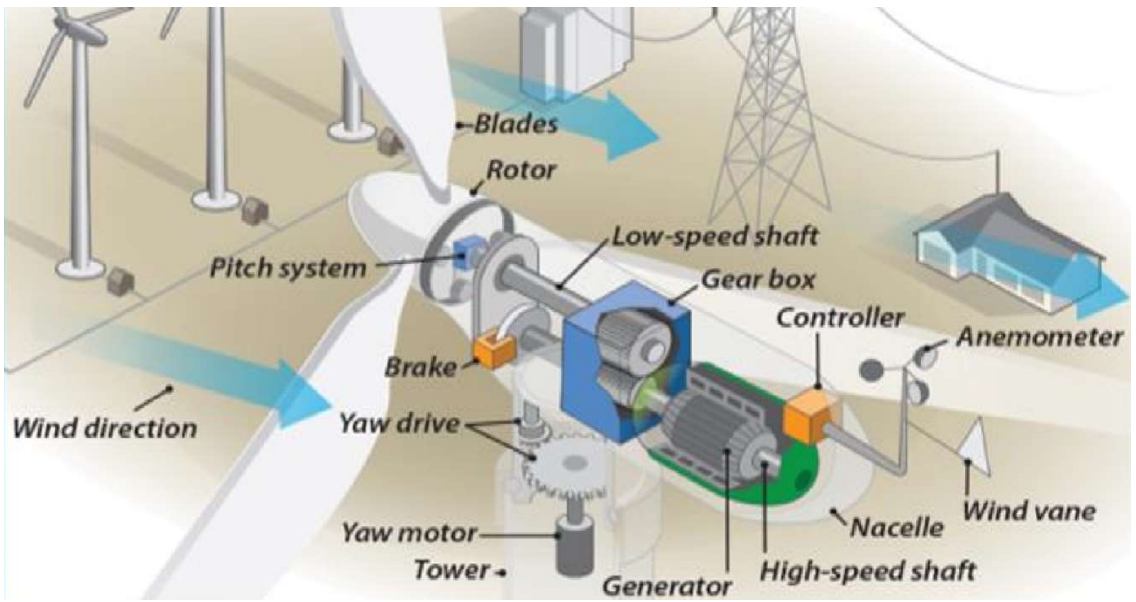
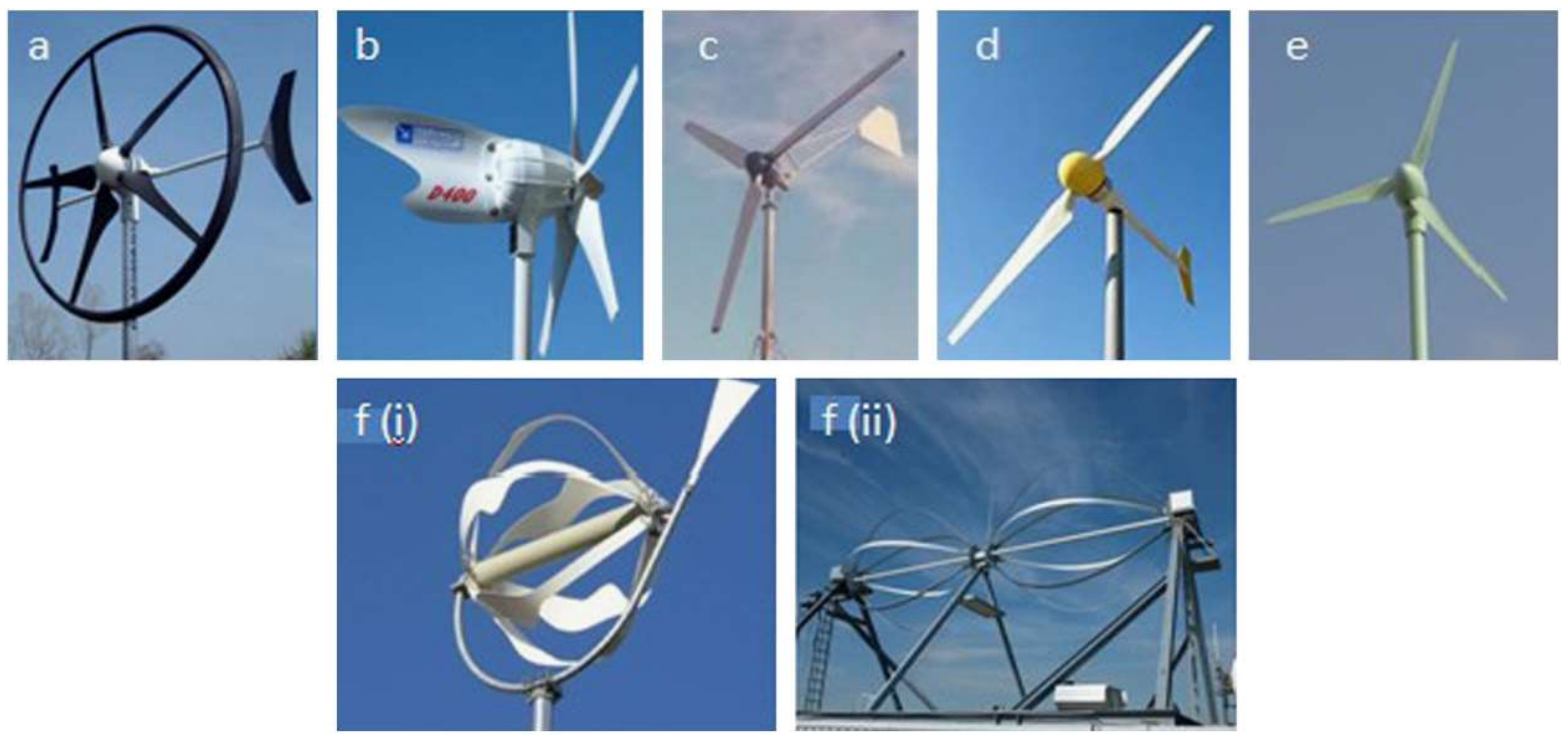
3.2. Horizontal Axis Wind Turbine

The horizontal axis wind turbines (HAWTs) are the most used types of WTs, especially in urban locations. They tend to have higher efficiency even on a small scale, and thus are highly recommended [69]. The axis of rotation for the blades is positioned horizontally [57]. The movement of the air via the blades transforms the energy in the wind to rotational shaft energy. A propeller-type rotor is fixed directly on the horizontal axis and directed continuously towards the wind with a yaw motor [58,59]. The yaw mechanism consists of a yaw drive, ring gear, bearing, shaft pinion, reduction gear, and brake. Yaw drive either can be an electric or hydraulic motor. The torque applied on the brake disc mounted between the tower flange and the yaw bearing is used to fix the rotor according to the wind direction [70]. Figure 6 shows the different components of the HAWT system.
The propeller-type rotor can be one, two, three, or more blades. The fewer the number of blades, the faster rotation of the rotor and the more structure support required for the WT system, with the 3-blade rotor as the most efficient rotor type. HAWTs are sensitive to wind direction and speed; hence, when there is a change in the wind direction or the presence of any form of obstruction, its performance is likely to decrease, especially in an urban environment [59,62]. The other limitations associated with the HAWT have to do with threats posed to birds and aircraft. Maintaining the turbines as well as the manufacturing and installation costs due to their height are always challenges. The blades for the HAWT, being very large, is also another problem as they cannot be suitable for all locations, especially in cities and towns [72]. To increase the wind speed and power coefficient for a mid-sized HAWT, a shrouded or lens turbine was used for some applications [73]. The mechanical control of the wind turbine can be classified into four modes based on the level of wind speed, i.e., below the cut-in, between the cut-in and rated wind speed, between the rated and cut-out wind speed, and above the cut-out wind speed, as in the wind power curve. The three main control modes are parking, generator, and pitch control. During the parking mode, the blades are completely pitched out of the wind direction and the mechanical brake is applied when the wind speed is below and above the cut-in speed and cut-out speed of the turbine, respectively. During the generator mode, the turbine operates at a variable rotational speed corresponding to different wind speeds between the cut-in speed and rated speed; the blades are therefore pitched into the wind direction with the optimum attack angle in order to track the maximum power point (MPP) (highest power coefficient Cp). This can be reached using proper control of the generator. In the pitch mode, the extracted power from the wind is kept constant between the rated and cut-out by gradually pitching out the blades from the wind direction, and the generator delivers the rated power. Most of the wind turbines in Figure 7 uses fixed blades, except the Scirocco, which has similar characteristics of large turbines, such as pitch-varying blades. A summary of the varying orientations for a HAWT is captured in Figure 7; the features for these types of turbines are also summarized in Table 1.

3.3. Vertical Axis Wind Turbine

The vertical axis wind turbines (VAWTs) are designed to allow the turbine’s blades to rotate in a vertical path [77]. The merit of these types of turbines is that there is no need for any yaw mechanism to position the turbine in the wind direction, hence making them ideal for urban applications [78]. Similarly, the installation of the gearbox and the generator is easier, since these components are often positioned closer to the surface of the ground. These characteristics also ensure that any maintenance can easily be carried out. The design of the VAWTs makes them also suitable for producing energy at a small scale even under turbulent conditions and varying wind velocity compared to the HAWTs; this fact supports the reason for their high application in urban communities across the globe. The energy produced using the VAWT is typically used at the same generation location. VAWTs are ideal for small-scale purposes, as the energy obtained is less than that from the HAWTs [79]. The application of a VAWT, especially in urban areas, keeps increasing because it is easy to install and cheaper than other types. They can easily be scaled to any size and can be installed at an elevation closer to the ground surface. Additionally, their effect on birds and aircraft is lower. These factors are contributing reasons leading to an increment in the market share for these types of turbines [80].
Darrieus, Gorlov, Giro Mill, and the Savonius are the commonly used types of VAWTs. The limitations associated with the HAWTs have also played a key role in the development of small-scale variable-pitch VAWTs with a suitable blade-pitching technique. The application of a kinematic couple to the turbine’s pitching mechanism can also significantly reduce all power required for pitching the blade. This method will allow the blade pitching to be carried out easily [81]. Developing a pitch mechanism for a VAWT that can easily move in the direction of the wind will be a massive boost in this technology, especially in recent times where researchers are exploring generating energy in cities even at varying wind speeds and quick changes in wind directions [82]. To reduce the turbine structural loads, current investigations on VAWT blades are primarily aimed at reducing the weight for the entire system and the various attached components [83]. This will lower the deformations due to bending as well as torsion caused by large transverse centrifugal loading. If not checked, this phenomenon is likely to significantly impede the efficiency of the turbine when in operation. Today, composite blades are used, which are almost the same as flying cyclocopter blades, as these blades can sustain the rotor’s speed. The different types of VAWTs are to be discussed in more detail, due to the different characteristics each design has.

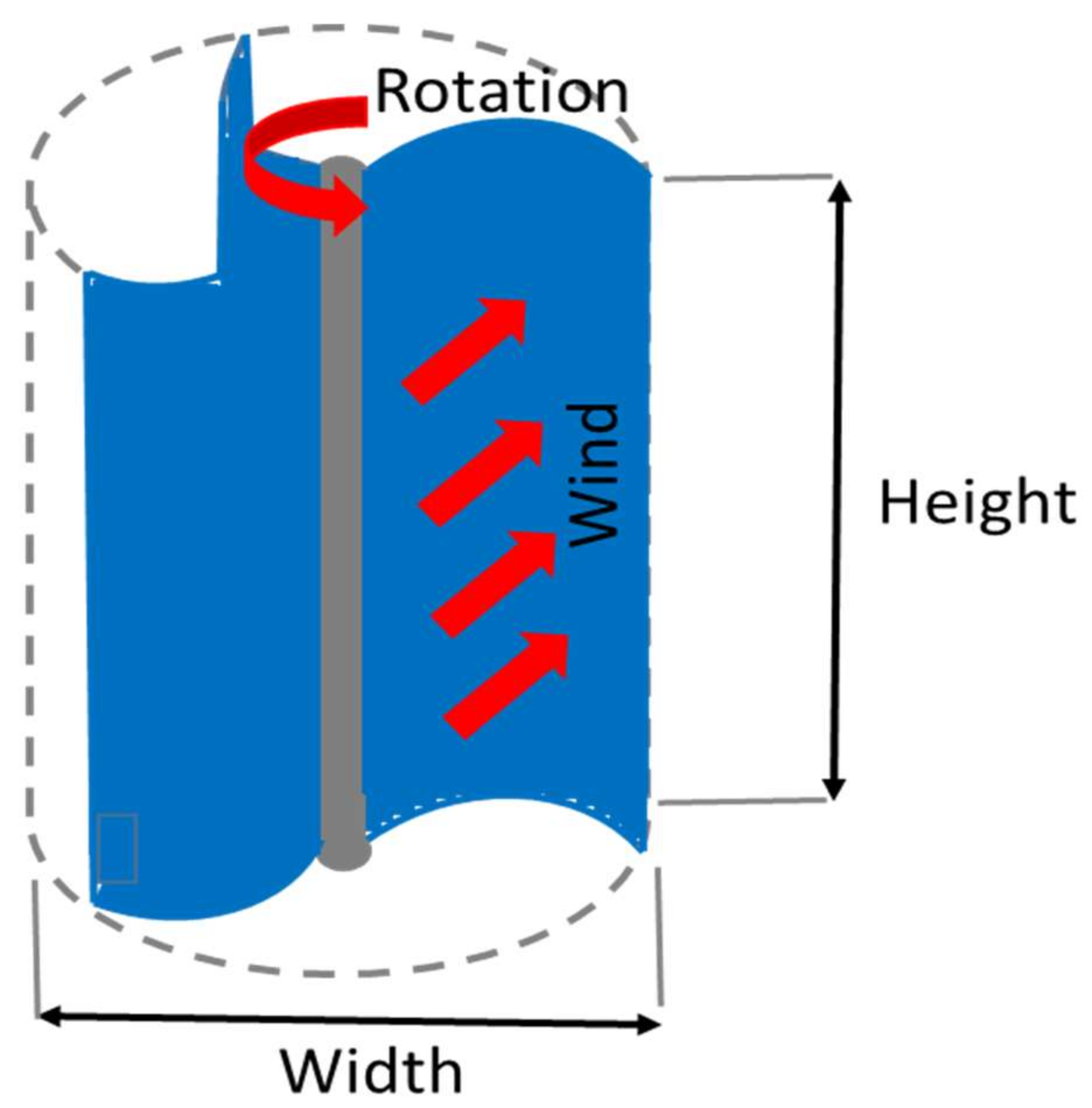
3.3.1. Savonius Vertical Axis Wind Turbine

The development of the Savonius types of VAWT can be traced to the 1920s. It was designed to function using drag force [84,85]. It is very simple with a lower cut-in wind speed. They are made up of two half-cylinders that are usually positioned opposite each other, forming an S-shape, as depicted in Figure 8. The main limitation associated with this design has to do with issues of lower aerodynamic performance compared to similar turbines. When the reliability of power is preferred compared to turbine efficiency, Savonius type is usually preferred. More research activities are being conducted on the Savonius design mainly to make them efficient for all locations, particularly in cities. Some of these activities include modification of the rotor design coupled with the shape of the blade. The rotor’s design for this type of turbine is unique, especially in terms of how torque is generated. The rotor design is directly proportional to the power coefficient that can be generated. An investigation conducted using a two-bladed Savonius turbine for small-scale power purposes recorded an increase of 34.8% in performance compared to other types of Savonius VAWTs [86].
Similarly, the computational technique for the same turbine blade number also recorded the impact of drag force on the turbines. Still, the researchers also highlighted some negative implications on the aerodynamics of the turbines [87]. The drag force supported the spinning of the turbines but affected the aerodynamic characteristics negatively. Research activities today are being conducted to determine the implication of varying the number of turbine blades, orientation, and the effect on the system’s performance when the blades overlap [88,89]. The effect of the number of blades, endplates, aspect ratio, and rotor stages coupled with the rotor accessories on the performance have all been investigated [90,91]. Other investigations have considered the effect of the Reynolds (Re) number as well as the turbulence scales coupled with the stator parameters. It was deduced that a suitable model will be needed for predicting the overall efficiency of the turbine. Exploring other shapes for the rotor for the Savonius type will equally increase the marketability and further accelerate their commercialization. The main limitation of the investigation carried out was the characteristics of the flow of the wind and the turbine’s design. Figure 9 below shows the rotation speed for different blade types/shapes, showing that a straight blade has the lowest rotation speed, and thus lower power output, while twisted and curved types have the highest.

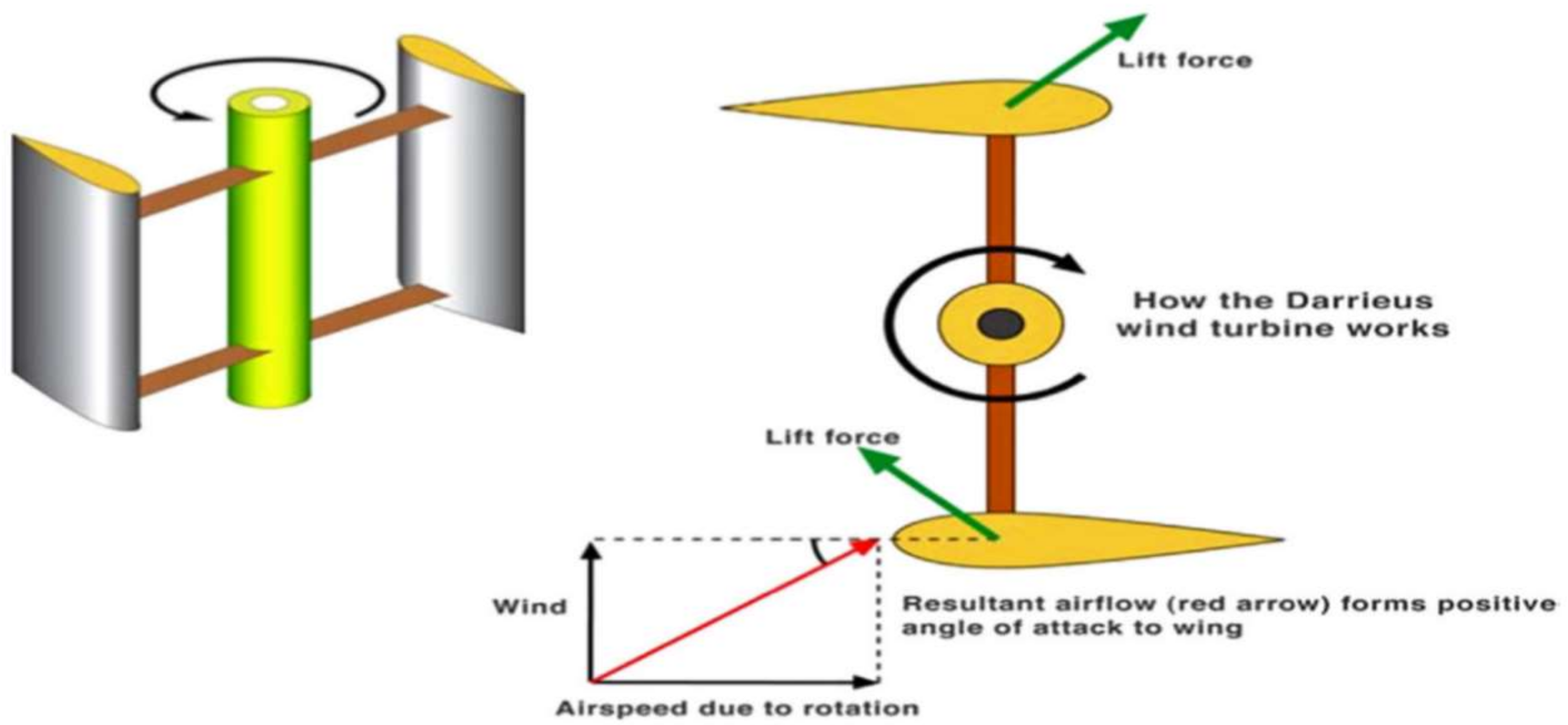
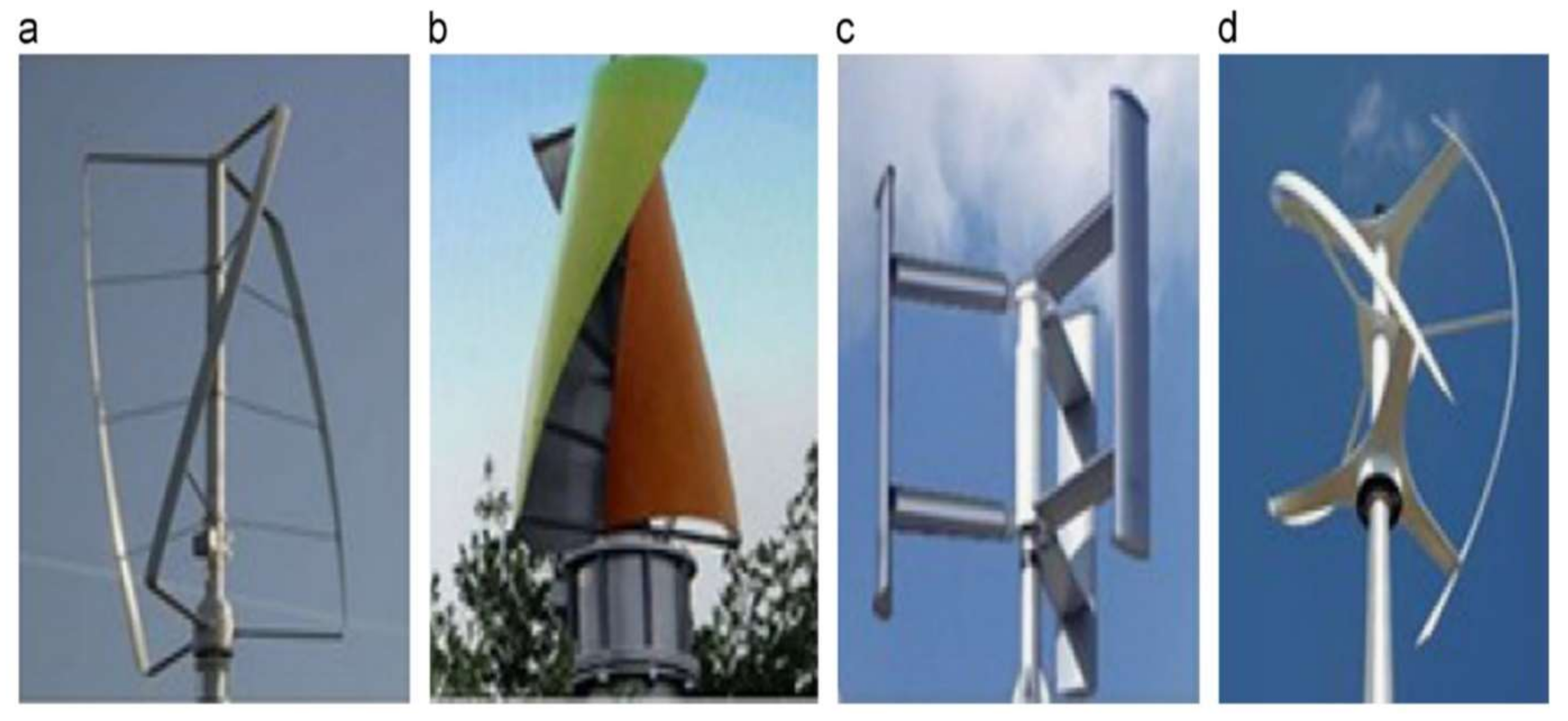
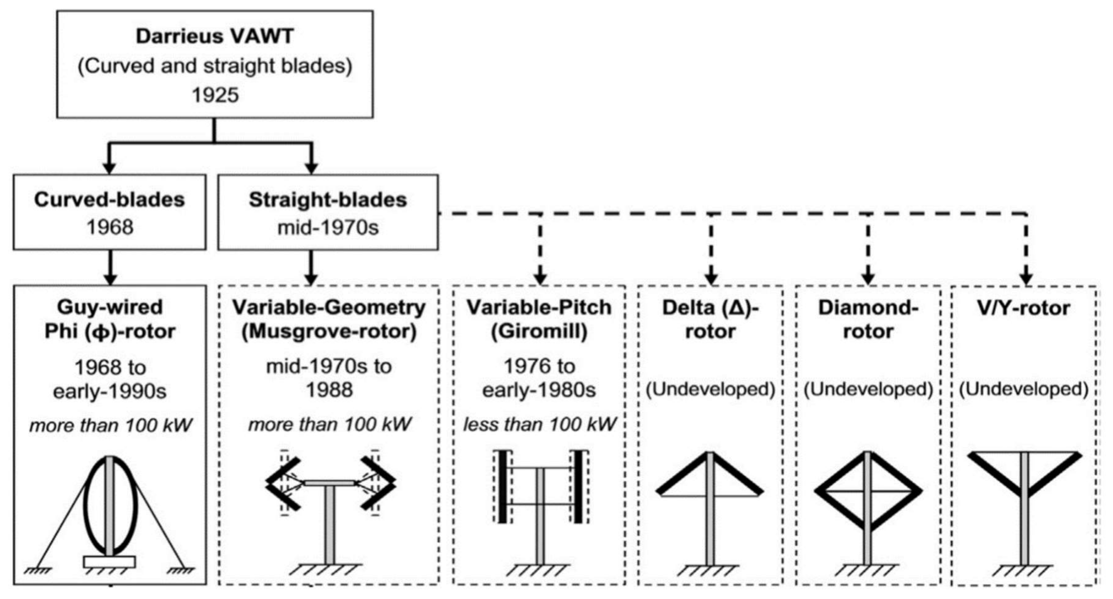
3.3.2. Darrieus Vertical Axis Wind Turbine

The history of this type of WT can be traced to the early 1920s. The performance of the Darrieus type is higher in terms of its aerodynamic characteristics and cheaper in terms of manufacturing. The Darrieus design is simple compared to that of the Savonius. They are developed based on the lift force and can produce more energy from the wind than the other types. They are further designed to move in a circular path via the air and relative motion between the wind flow direction, as depicted in Figure 10; the other types of Darrieus VAWTs are depicted in Figure 11. The design of the Darrieus reduces bending stress as well as the external force being exerted on the blade. They normally come in 2- or 3-curved or -straight blades having an airfoil cross-section. Figure 12 shows the historical advances in the Darrieus VAWT designs and shapes since the early 1920s. The main limitation of this type of turbine is that external force must allow the turbine to start. The financial projections for these turbines are very low. The high initial cost for the development of a good concrete foundation has largely contributed to their stagnation in commercialization. Systematic research was also performed to develop straight blades for Darrieus turbines [93,94]. The straight blade design is simpler than the curved ones, and their performance is also higher.
The selection of the wind turbine conversion system technology depends on four main categories, namely, the alignment of the rotation axis, generator types, speed rotation, and the type of control action. The horizontal axis wind turbine (HAWT) with a fixed speed rotation uses a squirrel cage induction generator (SCIG), while both the HAWT and vertical axis wind turbine (VAWT) with variable speed (limited or widely) use the squirrel cage, wound rotor (WR) with external resistance or with partial power electronics, such as a double-fed induction generator (DFIG), a permanent magnet synchronous generator (PMSG), or synchronous generator (SG), or with full-power electronics, such as a WR or permanent magnet (PM). In addition to the WT speed rotating according to the level of wind speed, the VAWT used on-site accepts wind from all directions and at a lower level of wind speed and speed rotation compared with the HAWT. Moreover, the optimum combination between the aforementioned four categories should be considered according to the specific location and the application type, i.e., onshore, offshore, building-integrated, and remote areas. Furthermore, the final optimum selection of the wind turbine system technology is based on the energy production, cost, and capacity factor.

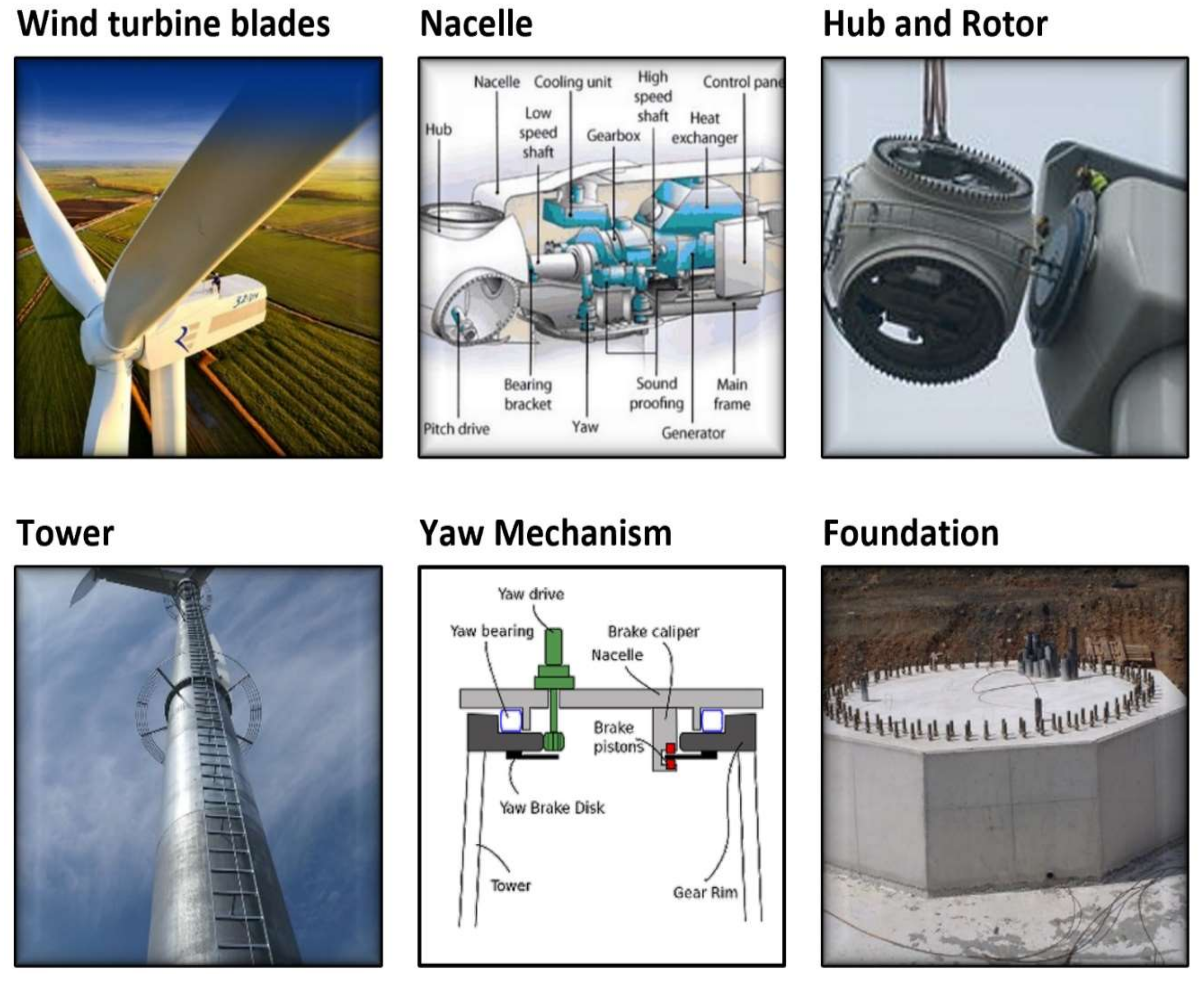
4. Design of the Wind Turbine System
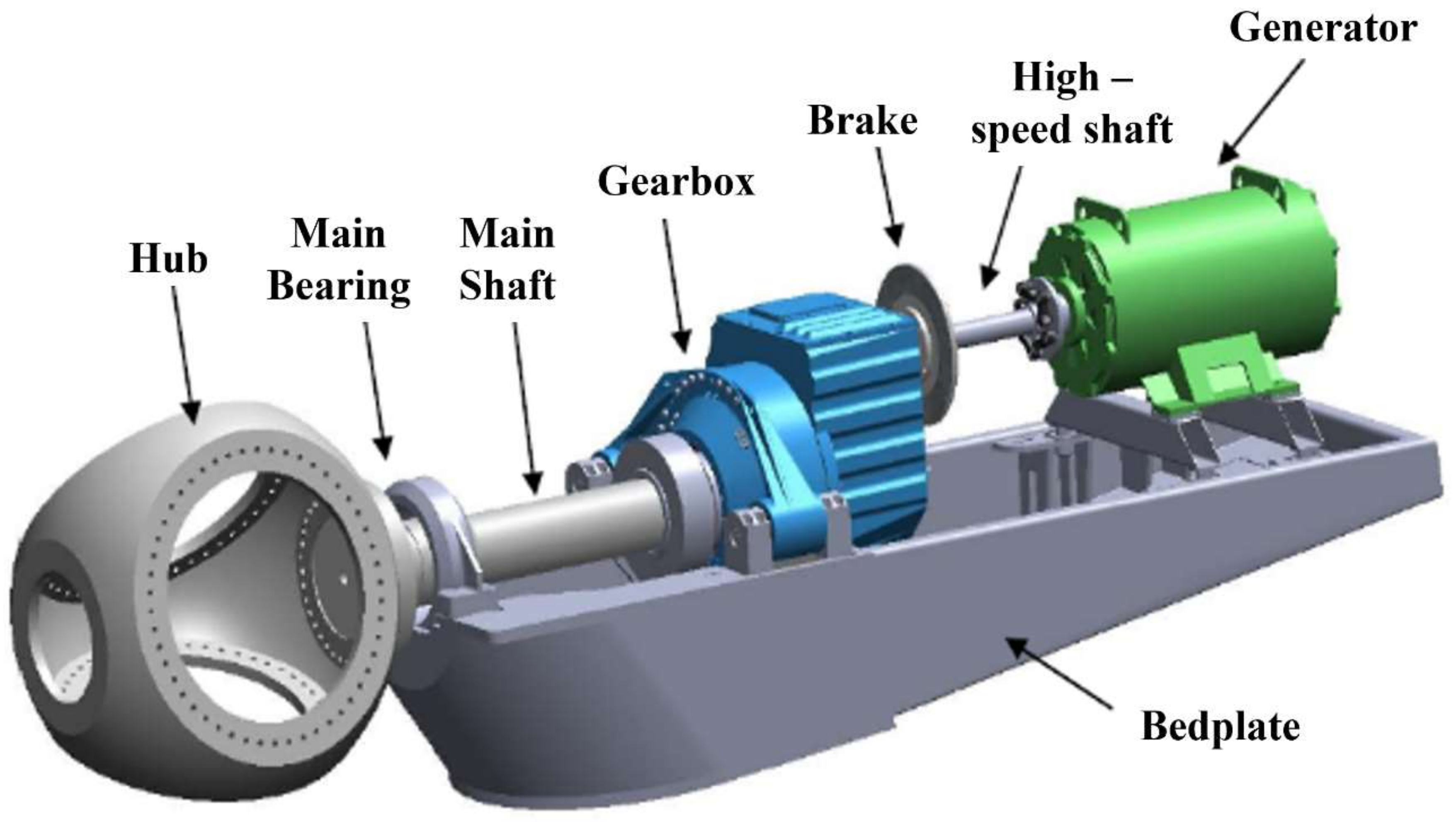
Wind turbine systems are made up of electromechanical systems that are very complex with several parts. There are key factors that determine the selection of the size and design of the WTs. Some of these factors include the site characteristics, demand, and wind profile. The overall aim of this is to reduce LCOE. A WT’s system is made up of more than 8000 parts, but these parts are usually subdivided into six main parts, as shown in Figure 13: the blades, nacelle, hub and rotor, tower, yaw mechanism, and finally the foundation [96,97]. The performance of the WT system revolves around all the components functioning properly, but the blades, Nacelle, and tower are key parts for the overall performance of the WT system.
The foundation supports the tower, which also eventually keeps the blades and nacelle in position, and is built to sustain the weight of the nacelle and the blades. The key characteristic of the tower is to be able to oppose varying wind speeds; hence, they are expected to be very rigid and strong [61]. To cut down costs, the tower can be manufactured in different components and rather assembled at the installation site to cut down the cost of transporting the huge tower. Offshore WTs are designed to be heavy compared to onshore WTs. Corrosion is another key issue that must be addressed during the development of WTs. The material characteristics of steel make them suitable for WTs. Some of these characteristics include high stiffness, strength, and cheapness [77]. The main limitation associated with the application of steel for WT towers is the welding of the components. It is further recommended that the towers be coated to curb issues of possible corrosion, which is likely to reduce the turbine’s efficiency [78].

4.1. The Drivetrain

The power generated from the WT is mainly dependent on the contact between the rotor blade and the wind. The rotor is designed to be made up of large turbine blades and the hub, as shown in Figure 14. The nacelle is considered the heart of the WT system. They are typically designed to be spaced to allow easy maintenance of the parts when necessary. The HAWT maintenance has always been an issue due to the position of different components within the drivetrain. The material for building the nacelle is recommended to be light in weight. They must be easy to mold as well as able to resist corrosion. The turbines, being subject to various bending stresses, need an alternative approach to sustain these stresses. A large load can be applied to the bedplate, making it deflect to sustain any unfavorable loading conditions. Even though this technique is considered a safety mechanism, it can easily result in misalignment of the bedplate and the nacelle. The overall effect of misalignment of the shaft has to do with the bearings becoming worn out and this is likely to increase the maintenance requirements [98].

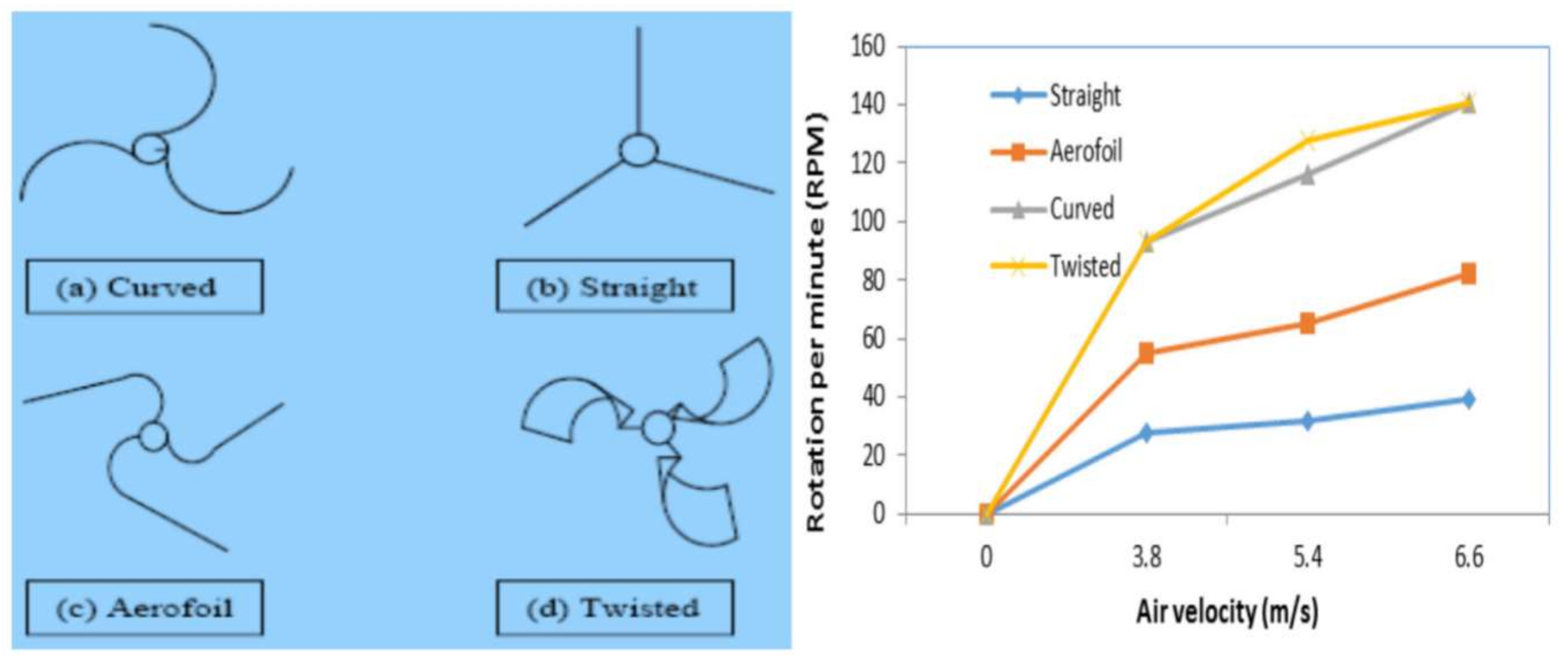
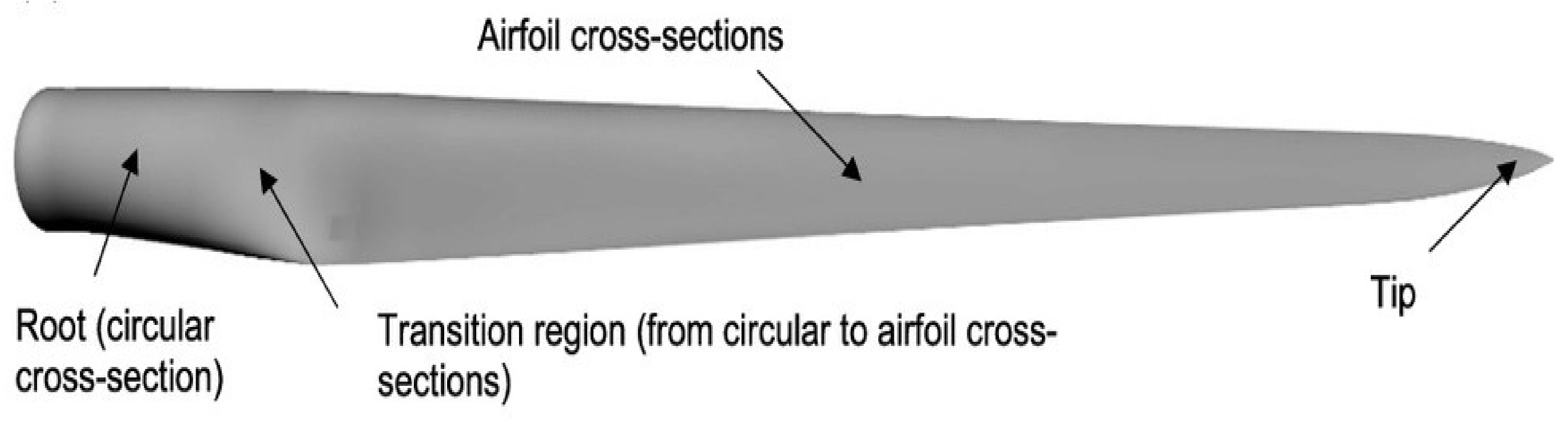
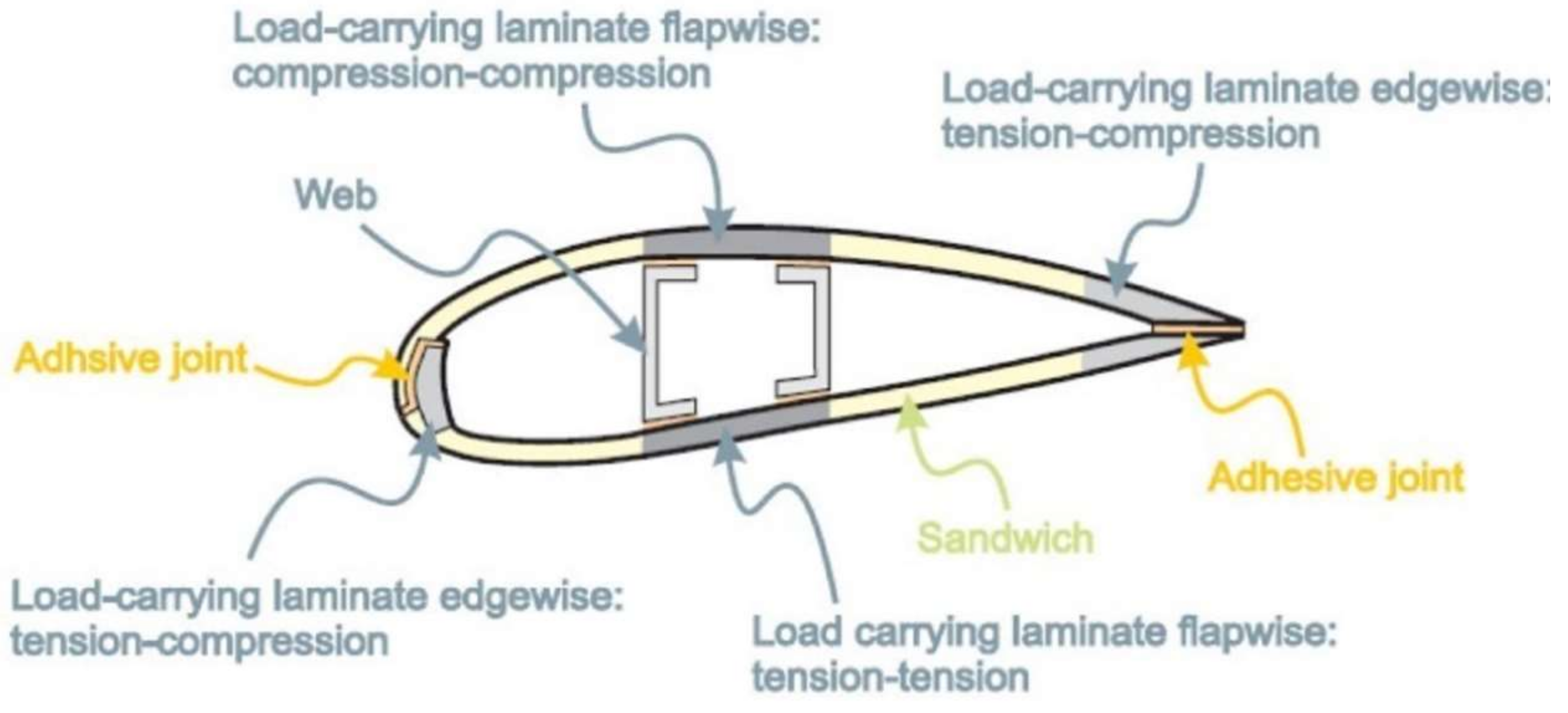
4.2. Wind Turbine Blades

The root, chord, midspan, and tip are the main parts of the WT blades, as shown in Figure 15. The parts are designed to support uplifts. The turbine tips result in the development of a helical vortex. The roots are built to sustain varying stresses exerted on the blade-like compression, twisting, and tension [100]. The chord is designed to sustain the lift while the midspan supports the bending and shear stresses. The WT blades are designed to have two faces for pressure and suction. The faces are connected with the aid of shear webs linking the upper and lower parts of the blades together, as shown in Figure 16. Force due to gravity coupled with torque load also results in the development of edgewise load. Edgewise bending is supported by the profile edges. A flapwise load is created as a result of the wind pressure. The spar opposes the flapwise bending. A laminate inside the spar goes through cyclic tension–tension loads [100]. The other area is subjected to cyclic compression–compression loads. There is also tension–compression loads on both the trailing edges and the leading laminates to accommodate the bending moment. Elastic buckling is curbed with the help of the aeroshells. Due to the varying loadings for different locations, it is recommended to use different materials for different blade sections [82].

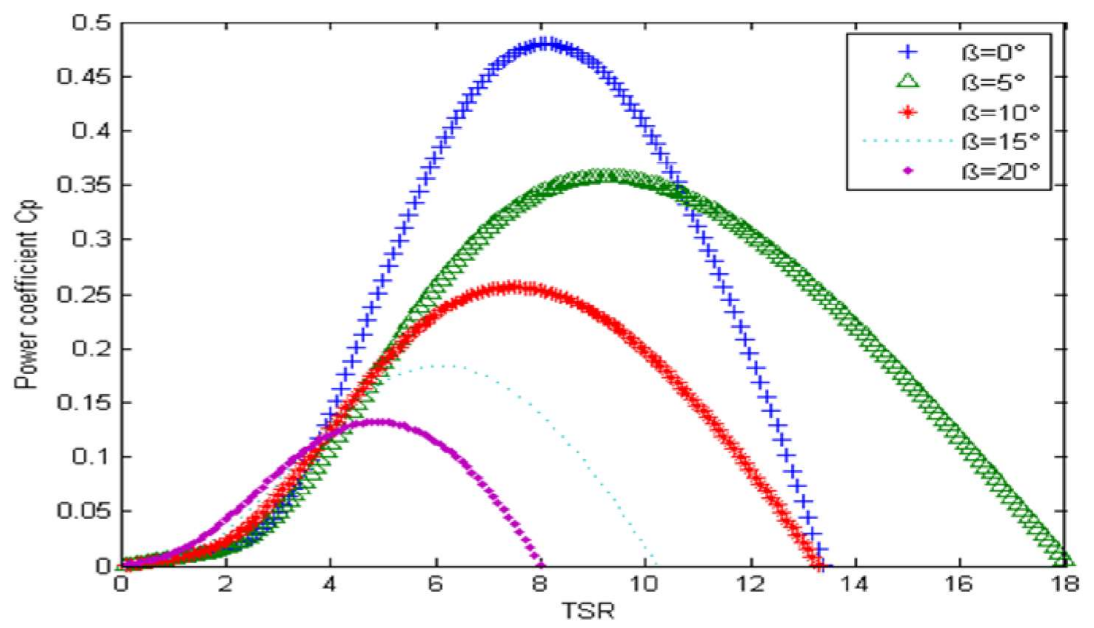
4.3. Wind Aerodynamic Model

The movement of air, or any fluid, on any surface leads to the creation of two forces, namely, drag and lift forces. These forces are responsible for developing the torque required to keep the turbine blades in rotational motion. The characteristics of the energy generated by wind energy can be expressed by the power generated, power captured, power coefficient, and the tip speed ratio [102]. The power obtained from the wind is expressed in Equation (1) as
P w = 0.5 ρ π R 2 V w 3
where Pw is the power that can be generated from the wind, ρ is the density of air, R is the radius of the turbine, and Vw is the wind velocity.
The turbine blade’s ability to capture power from the wind is represented in Equation (2) as
P b = 0.5 ρ π R 2 V ω 3 C p λ , β
where Pb is the power captured by the turbines, Cp is the power coefficient which is a function in: λ is the tip speed ratio (TSR), and β is the pitch angle.
The power coefficient can be calculated using Equation (3).
C p λ ,   β = 0.5176 ( 116 λ i 0.4 β 5 ) 21 λ i + 0.0068 λ
λ i can be calculated using Equation (4).
1 λ i = 1 λ + 0.08 β 0.035 β 3 + 1
The tip speed ratio TSR is the ratio of the turbine’s angular velocity to the wind speed, which can be calculated using Equation (5).
λ = R ω r V w
where ωr is the rotational speed.
The mechanical torque for the turbine is captured in Equation (6).
T m = 0.5 ρ π R 2 V ω 3 C p λ , β ω r
An investigation carried out with the aid of MATLAB to explore the correlation between the TSR (λ) and the power coefficient (Cp) at different pitch angles (β) deduced that when the pitch angle is low, the highest Cp is generated, with the maximum Cp being obtained from a specific TSR λ, as shown in Figure 17 [103]. The figure further highlights the fact that the highest Cp cannot go beyond the Betz limit, which is 0.593, as the theoretical maximum obtained efficiency of a WT [84]. The value of Cp also depends on the number of blades used for the rotor, as shown in Figure 18. The figure shows a higher achieved power coefficient for three, four, and five blades at a lower λ, while one and two blades achieved a lower power coefficient at a higher λ [104,105]. This information is very critical, especially in the characterization of converters for electrical wind systems.

4.4. Wind Energy Conversion Systems

Mechanical energy generated due to the blades rotating is transmitted to a generator’s rotor, which eventually produces the electricity. The power generated can be used directly or transmitted to the grid via a transformer. The linking of the turbine to the grid is carried out at varying voltages. Subject to the rotation of the turbines, wind energy conversion systems can be categorized into two types: fixed speed and varying speed. The fixed speed, as the name suggests, is designed to be functional at a consistent velocity. This implies that despite the speed of the WT, the rotor will keep its angular speed fixed for these types of turbines and this is also determined by the gear ratio and the supply frequency. The main limitation of such a system is the fluctuation in wind power and its implications on the grid. For the variable speed system, the torque from the generator is maintained whiles the speed is varying. The power being generated can be increased, provided a power converter is utilized to adjust the generator’s speed. Figure 19 shows a basic layout for a wind energy conversion system.

4.5. Generator for Wind Energy Conversion Systems

Generators are specifically classified as (DFIG) and permanent magnet synchronous (PMS) generators. These generators are very reliable, hence their high application in the wind energy industry [107,108]. Alternating current (AC) generators are commonly used compared to the direct current (DC) types. The AC generators are predominantly utilized because they are cheaper to use and maintain.

4.5.1. Asynchronous Generators

Induction generators, due to their operational characteristics, have also been recommended as ideal in harnessing energy from the wind [109]. Characteristics such as an excellent dynamic response and brushless assembly are key facts making the reliance on these types of generators grow. They are designed to guard against short-circuiting. During operation, induction generators are designed to be supplied with reactive power for the generation of a magnetic field. The induction generator that functions with the aid of a grid is supplied with reactive power from the grid. The grid’s reactive power can be supplied to the induction generator using a power electronics converter and capacitors called self-excited induction generators, especially for stand-alone applications [110]. These generators are also recommended particularly for small power plants due to the low maintenance cost and the capacitors needed [111,112]. There are two main categories of induction generators utilized in wind energy conversion systems, subject to the rotor. These are the squirrel cage induction generator and the wound rotor induction generator. The wound rotor induction generator is considered a DFIG once it is appropriately configured. Variable speed operation can be carried out via a connection between the rotor circuit of DFIG with the aid of an external variable voltage using a mechanism such as a carbon brush or slip rings. The external variable voltage can be achieved by variable resistance (rheostat) or using power electronic devices.

4.5.2. Synchronous Generators

Synchronous generators use a wound rotor or permanent magnet based on the type of drive train if it is indirect or direct. Permanent magnet synchronous generators (PMSG) with full-power electronics devices are currently being used to produce electricity from gearless WTs [113,114]. These types of generators’ self-excitation characteristics are leading contributors to their high application in wind energy conversion systems in recent times [115]. PMSGs can be operated with or without gear. Increasing the number of poles can increase the power being generated from these types of generators. This can be linked directly to the grid again in the absence of a gearbox. This approach normally reduces mechanical loss and the construction and maintenance cost [116,117]. These generators are ideal for variable-speed wind systems because they exhibit a lower weight and size, and hence are suitable for low-power wind energy systems [118]. The main merit a permanent magnet has over the wound rotor induction generators has to do with a gearbox not being needed. This, therefore, leads to an increment in the efficiency of the system as well as making them more reliable. The number of poles required for PMSGs are higher compared to other types of generators due to the absence of a gearbox.

4.6. Power Electronics

The movement of air naturally is erratic, with wind speed and direction pattern varies daily and seasonally, this presents an operational challenge. Power electronics are designed to ensure the system is reliable and efficiency is improved by reducing mechanical stresses that are capable of affecting the system performance adversely. The entire wind energy conversion system is designed as a generation unit and hence can be fixed to a grid easily [119]. The variable-speed operation is more favorable than that of the fixed-speed system. The variable-speed operation reduces mechanical stress as well as ensures the maximum power is captured, with easily controllable generation for smooth grid integration [120]. The power electronics used for variable-speed WTs are depicted in Figure 20.
Generating power even for the fixed-speed WTs still requires a power electronic device called thyristors, especially if it is to be connected to the grid. Thyristors are used as a soft starter. However, it must be noted that the utilization of these power electronics is more likely to increase the overall cost of the system. Despite the downside of the power electronics, its effect on the system in terms of reducing the mechanical complexity and sustaining all mechanical stress exerted on the system makes it appealing to the wind energy industry. As captured in Figure 20f,g, the power electronics’ presence as part of the system can expunge the need for any gearbox. This implies that the system’s losses are more likely to lessen as these losses are often associated with the gearbox. Several converter technologies are currently being employed in the wind energy industry [121]. A two-level voltage source converter is the DFIG and PMSGs, which are utilized in the wind energy industry [122,123]. To sustain the higher power from the generator, these power converters can be connected either in series or in parallel. These changes again will add up to the system’s complexity, hence increasing the entire cost of the system. A back-to-back pulse width modulation current source converter method is being used for applications that demand high power [124,125]. Adapting this technique enhances the performance for excellent grid integration [124]. Issues about overvoltage due to the switches communicating are the main downside of this technique [125].

5. Selection Guidelines for Wind Energy Technologies

The model of turbine chosen has also been given careful consideration. Sarja and Halonen [126] used semi-structured surveys with domain experts to identify multiple selection parameters, including commodity efficiency, manufacturing volume, cost factors, availability factors, as well as maintenance organization. Selection parameters are ranked subject to the priority depending on the results of the surveys. While it was not feasible to create a comprehensive and prioritized set of selection requirements, as described in their report, some general trends appeared. The study’s biggest flaw was that it did not have a statistical model that could calculate the outcomes and help with decision-making. The diameter of the rotor, generator capacity, hub height, pitch angle range, and rotations per minute (RPM) range were defined as five selection parameters by Perkin et al. [127]. These parameters were incorporated into the chromosome encoding of a genetic algorithm used to find the right turbine. This was an intriguing technique, but the use of a genetic algorithm made it computationally costly. Nemes and Munteanu [128] proposed a method for comparing nine separate wind turbine models based on device-efficiency indices. Chowdhury et al. [129] used a particle swarm optimization algorithm as the underlying optimization algorithm to choose wind turbines based on a single parameter—energy output capability. Moreover, only one kind of wind turbine was considered. The problem in this circumstance was the algorithmic and numerical difficulties associated with particle swarm optimization, as well as the precision of the decision method according to a single criterion, similar to Perkin et al. [127]. To choose the turbine, Firuzabad and Dobakhshari [130] used a probabilistic model dependent on turbine reliability, assuming five turbine forms. The decision-making mechanism was also limited by the fact that only one goal was weighed. Bencherif et al. [131] used the power factor as a criterion for choosing between 24 turbine models. For collection, an empirical method focused on the Weibull distribution was used. Montoya et al. [132] suggested Pareto ranking-based genetic algorithms for selecting the right turbines, with power production and regular power output variation as decision parameters. Chowdhury et al. [133] used the expense of energy optimization as the turbine selection factor, with 121 separate turbine models. However, the statistical sophistication of their proposed method was a concern. Martin et al. [134] used a variety of wind environments to refine the rotor-to-generator ratio for a hypothetical wind turbine. However, since many other important variables involved in the turbine selection phase were not included in the study, the approach can only be used as a support tool rather than a full selection system; it was claimed that the technique can only be used as a support tool rather than a complete selection method. Bekele and Ramayya [135] suggested a site-specific wind turbine concept that took blade design into account as an optimization component. The blade form was optimized using a genetic algorithm.
One theoretical disadvantage of this solution was that it did not use off-the-shelf turbines, necessitating complete site customization. Helgason [136] used 47 separate turbines to perform an analysis on many possible locations in Iceland. The minimum cost of energy was viewed as an optimization parameter and was modelled as a function of estimated annual energy generation, power factor, and cost of energy. Similar problems were encountered by Eke and Onyewudiala [137], whose solution was to develop a site-specific turbine based on form parameters such as the chord, curl, and relative blade thickness. The plan was to change the specifications of two existing turbines in order for the modified version to produce more electricity. The genetic algorithm was used, but the three decision factors were not addressed in the optimization phase. Jureczko et al. [138] suggested a genetic algorithm-based method for turbine design that took into account blade vibrations, performance, blade material expense, blade structure stability, and blade structure strength specifications as the design parameters.
For a location in Jowder, Bahrain [139] suggested a selection method that used the power factor as the decision variable. Furthermore, the report just looked at six commercially available turbines. El-Shimy [140] suggested a site-specific turbine selection method that took the ability factor, standardized average power production, and the turbine-performance index into account. One disadvantage of the method was its ambiguity and subjectivity, as the findings necessitated in-depth explanations by a domain specialist, and the interpretations may differ from individual to person. Abul’Wafa [141] suggested a formula for matching wind turbine generators to a location that combined the turbine output index (TPI) with the minimal deviation ratio (DR) between the rated and optimum speed of the wind turbine generator (WTG), resulting in the lowest energy expense. While the paper appears to have evaluated twenty-five possible turbines, the report only contains the findings and description of a handful of them. For turbine selection, Dong et al. [142] suggested three criteria: the matching index, turbine cost index, and combined matching index. Particle swarm optimization, differential evolution, and the genetic algorithm are used as the optimization algorithms.
Shirgholami et al. [143] listed more than 30 judgment parameters that have been used in the literature and are the most applicable research to the analysis proposed herein. However, it was discovered that in some circumstances, only a subset of the specified parameters may be included. Shirgholami et al. used 11 decision criteria in their research, including power factor, rotor quality, lifetime costs, initial capital costs, operational and maintenance costs, environmental concerns, wildlife effects, noise pollution, visual effect, supplier results, satisfaction level distribution, and political stability. Furthermore, the report just looked at four different models of wind turbines. The decision-making method was focused on the Analytic Hierarchy Process (AHP) [144]. Bagocius et al. [145] conducted a related analysis and suggested a turbine selection method for offshore wind farms. They used a system called WASPAS, which is similar to the AHP process. Five factors were considered: the wind turbine’s nominal output, the maximum power produced in the region, the amount of electricity extracted each year in the area, expenditures, and CO2 emissions. Furthermore, only four different kinds of turbines were evaluated. Lee et al. [146] proposed a multi-criteria decision-making method that took into account the four main decision criteria: machine features, economic factors, environmental concerns, and technological challenges. However, one significant flaw in their research was that it concentrated solely on evaluating the relative value of the four decision criteria, rather than demonstrating how this was applied to real-world turbine results. Since the decision process included certain rather technical sub-criterion, real evidence for this sub-criterion was almost difficult to procure from transparent sources or suppliers, rendering the solution less realistic. In their research, they used only four turbines with a nearly identical rated capacity.
The selection of the wind turbine conversion system technology depends on four main categories: alignment of the rotation axis, generator types, speed rotation, and the type of control action. Based on the wind direction in the site, the VAWT accepts wind from all directions on site and at a lower level of wind speed and speed rotation compared with the HAWT; in turn, the HAWT accepts wind only from a certain direction with the assistance of the yaw mechanism. In addition to the wind direction and based on the turbine speed rotation according to variation in the level of wind speed on site, the horizontal axis wind turbine (HAWT) with fixed speed rotation uses a squirrel cage induction generator (SCIG), while both the HAWT and vertical axis wind turbine (VAWT) with variable speed (limited or widely) use squirrel cage, wound rotor (WR) with external resistance or with partial or full-power electronics, such as a DFIG, synchronous generator, or permanent magnet synchronous generator (PMSG). Moreover, the optimum combination between the aforementioned four categories should be considered according to the specific location and the application type, i.e., onshore, offshore, building-integrated, and remote areas. Furthermore, the final optimum selection of wind turbine system technology is based on the energy production, cost, and capacity factor.

6. Technological Advancement in Wind Energy

6.1. Wind Turbine Blades

The blades of a WT today are designed to be made up of composite materials to support aerodynamic lift and this is later converted to electric power with the aid of a generator. The LCOE is largely due to the cost of the turbine and the blade, with blades presenting up to 25% of the total cost of the system [147]. The diameter for the rotor in the last few years has increased appreciably to increase the energy captured from the wind and ensure a reduction in the LCOE. This progress has led to several blade designs being developed, along with the material used to manufacture these blades.

6.1.1. State-of-the-Art Wind Turbine Blade Development

The structural capabilities, coupled with aerodynamic performance, determine the design of turbine blades. Most of the optimizations carried out on WT blades are primarily to improve the power coefficient and enhance the initial diameter of the turbine to increase the swept rotor area. The rotor swept area has a direct correlation to the amount of energy that can be captured. The blade’s manufacturing process is critical as it will directly affect their lifespan coupled with their reliability. Airfoil designs are often available for blade design, which is conceptualized in terms of the structural composition of the turbine blades and their features. The quest for manufacturing larger WT blades has resulted in the development of higher structural loads. This phenomenon has led to the development of turbine blades that are slender in shape to limit the loads exerted on the blades and reduces the materials needed during the manufacturing of the blade. Further studies to prevent any deflection, such as the blades striking the tower, has recently become key research directions.
Models that can give good manufacturing methods coupled with tolerance must be considered in future investigations. These phenomena are key, especially for the trailing edge of the blade. It is also important to take into account the optimization of the entire system and not only the various components attached to the system. Optimization of the materials needed in the manufacturing of the turbine blade is also crucial as the material cost accounts for 50% of the overall turbine blade manufacturing cost [148]. The development of novel materials that are light, strong, and cheap will significantly reduce the cost of the current WT blades. Fiber-reinforced polymer composites due to their merits in terms of specific strength modulus and stiffness are often used as the turbine blade material. Despite the advantages associated with such composite materials, they have some limitations in terms of their failure modes being complex. There have been several investigations carried out on fiber-reinforced composite material utilized as a turbine blade material [149]. The type of laminate investigated included configurations that are unidirectional as well as multidirectional. Other investigations were carried out on the resins, adhesives, lap shear ply drops, as well as environmental effects [150]. Other research work also explored the impact of any defects in the materials used in the manufacturing of the turbine blades on their performance [151]. It was, however, deduced that these defects are likely to have an adverse impact on the structural performance of the turbine blades. Some of these defects include wrinkles, dry spots, and porosity [152].
Today, as a result of this optimization work, there is currently a database for materials suitable for WT blades. These databases equally come with design information as well as the safety factors ideal for these turbines. For a blade to become certified, testing must be carried out both under static as well as fatigue loading [153]. These comprehensive certification processes are both time-consuming and expensive financially; hence, it tends to impede the commercialization of new designs. The development of some of these novel designs is gradually making the wind energy industry consider the idea of composites being the sole material for these turbine blades. The diameter of the rotor in the last decade has equally increased by more than 36% [154]. The same can be said of the blade’s length coupled with the mass as well. The rotor diameter for offshore wind installation is current pegged at 115 m. These diameters are projected to increase to 153 m in the next few years [63]. The length of the blade in terms of growth in the last decade has not been proportional to the mass but the cost of these blades keeps increasing, as depicted in Figure 21 below.
A novel type of WT blade has its features optimized to improve the aerodynamic characteristics of the blades. Some of the optimization features include plasma actuator control of the vortex shedding, serration of the trailing edge, and mitigation strategies to reduce the level of noise in the system [155,156,157]. Today, there are pilot projects basically to automate the manufacturing process of the WT blade but that comes with its own cost. Until the hurdle associated with the cost in terms of automating the manufacturing process is jumped, the development of the blades will remain a tedious process with increasing labor cost. In the quest of increasing the performance of the blade via optimization of the blade length, issues pertaining to its interaction with high-rise buildings coupled with being exposed to the environment, and the labor involved, will persist. For example, to produce a large-scale blade design, the segmented ultralight morphing rotor can be optimized to reduce the mass of the turbines [158]. In terms of modularity, additive manufacturing is currently being recommended in the development of the molds to accelerate the manufacturing process of the blade.

6.1.2. Future Research Activities for Wind Turbine Blades

The quest to reduce the cost of WT blades is currently the ultimate goal for future developments in the wind energy field. A novel type of WT system is being designed to have larger turbine blades to capture more energy at a reduced cost. This is likely to cause a paradigm shift in terms of the design of the turbine blades coupled with the materials as well as the manufacturing process [160]. Optimization of the system is very important, but for the goal of reducing the cost of the technology, several measures must be put in place. Further research activities to expand the knowledge in this field will significantly change the sector positively. Collaboration between designers of the blade, suppliers of the materials, turbine manufacturers, and even the owners of the wind farm will be very crucial in the advancement of the technology. This collaboration is very common in vertically integrated wind energy companies. It is important that once a contract is signed for the development of the wind farm, sharing of data must be clearly emphasized in the contract to make all parts aware and prevent any future disputes and litigations. Designers of the blade must also be innovative to consider the structural needs of the blades coupled with the material required as well as the manufacturing process involved in building their concepts. Further investigations into modular blade designs to support dimensioning and alignment is very critical.
In the search for lighter blade designs, reducing the material to significantly improve the aerodynamic characteristics of the blades have been observed to come with some issue pertaining to buckling [160]. Sensors are currently being recommended to support data collection, especially in the case of any failure in the field. Some of these failures that are of interest include flaws during the manufacturing process, de-icing issues, and enhancing the tolerance of the turbine blades to any form of damage.
Innovation in terms of the materials required will also reduce the cost of the turbine blades. Even though composites are currently preferred due to the “stiffness per dollar”, further research and development efforts are still required to explore other materials that will reduce the entire cost of the system. Investigations regarding a reduction in the energy input coupled with the cost of carbon fiber should be an active research direction in the future.
Making the turbine blade design very complex is likely to expose it to varying forms of defects during the manufacturing process. It is therefore imperative that the designs are made fairly simple with the manufacturing process in mind. There are downsides of composites in terms of their fatigue characteristics. Future investigations must further explore the impact of imperfections, porosity, and residual stresses, coupled with the initiation of cracks, on the performance of the turbine blades. Issues amounting to the safety of all these novel turbine blades must be investigated and properly documented. Recycling of the turbine blades after their life cycle must also be evaluated properly. The application of thermoplastic matrix composites, as well as thermosets that can easily be recycled, should be the primary focus of all novel turbine blades being developed [161,162]. Reinforcements in future turbine blades must be made up of carbon fiber that can easily be recycled [163].

6.2. Towers and Foundation

The towers coupled with foundations are very critical components in the development of WT projects. Maintenance of these parts has always been a challenge, which is aggravated when dealing with offshore turbine installations. Key challenges during the installation process are the erratic characteristics of the wind and the difficulty in building these parts in such an environment, coupled with geotechnical challenges. There have been several innovations in offshore towers over the last few decades. Researchers have presented detailed information on the nonlinear analysis of offshore structures coupled with wave analysis. The work explored the post-elastic evaluation of the structural characteristics under offshore conditions as well as the effect of the breaking waves on such projects [163,164,165,166]. Unfavorable conditions, such as hurricanes, which usually lead to an increase in wind velocity and wave height, have also been investigated [167]. This phenomenon explains the need for a more reliable method for analyzing offshore WT efficiency. A technique that can be adopted to explain how environmental models can be utilized in the prediction of any likely hazard in offshore structures [159].
The Block Island project is one of the latest projects with newly installed jacket designs, as depicted in Figure 22. These jacket designs are normally built to suit a specific location. They normally require constant checks to ascertain the impact of hurricanes [159]. Some of the concerns raised pertaining to this project were the difficulty associated with inspecting these types of projects coupled with the extension of the support after its life span of 25 years.
Techniques for the assessment of the performance of the offshore structure when exposed to harsh loading conditions have also been reported [164,165,166]. Further research work into exploring the characteristics of these structures under nonlinear conditions will expand knowledge in this field. The operation of the Block Island wind farm in the United States is a clear indication of the feasibility of such offshore projects along the coast. The development of jacket support suitable for a particular location will imply that critical attention must be paid during the foundation design. Today, in Scotland, a pilot project is being executed on a commercial floating system and novel anchoring techniques [168]. This ground-breaking research will provide some flexibility during the fabrication and installation phases of the system. Further investigations must also explore novel models for the determination of harsh loading conditions. Similarly, a more reliable technique for the determination of the soil-structure interaction on structural performance should equally be an active research direction in the future. A floating system design requires more detailed research work. Techniques for measuring the risk associated with such projects should also be paramount in future activities.

6.3. Energy Storage Systems

The unpredictability associated with the wind speed and direction often results in stability and operational challenges [169]. Again, planning becomes very difficult as the amount of energy that can be harnessed from the wind is subject to the conditions at the moment on the site. This is where a suitable energy storage system will be very key in the entire functionality of the project. The storage system can store excess energy and supply this back to the load when demand is high, hence helping to smooth the energy generation profile. Some of the storage systems that can be considered include a flywheel [170,171], compressed air [172,173], supercapacitors [174,175,176], fuel cells [7,177], and batteries [178,179]. Different types of energy storage systems have been used in literature for wind energy systems [180]. To increase the performance of the energy storage system, some research combined various technologies. The absence of rotating parts that increase losses, such as a superconducting magnetic and secondary battery as an energy storage system, has also been recommended.
Control systems can also be integrated to regulate the frequency and damping power swings [181]. This in effect explains the fact that the control method has an immense impact on the system. Optimal utilization of battery energy storage system using a control scheme to level the intermittency during power generation, particularly on wind farms, have been reported [182]. The integration of wind energy storage systems has also been reported to be suitable for other applications, but their application in wind energy conversion systems significantly improves the power quality, coupled with ensuring the system stability [183]. Some benefits associated with integrating energy storage systems with wind energy conversion systems include suppressing power fluctuations and lower voltage ride through. Other advantages include serving as support for controlling voltage and peak shaving. Damping of oscillation is also reported as merit related to energy storage systems integrated with wind energy conversion systems [184].
Most research work being carried out recently is geared towards decreasing the losses and cost of energy storage systems. Reducing the cost of energy storage systems will equally improve its integration with wind energy projects [160]. In terms of electricity produced from wind, a good method is choosing an ideal storage technique subject to the operating conditions, usage, capacity, and power rating [180]. The life span of the current energy storage systems requires significant improvement. The sizing of these systems is also very critical and must be evaluated properly. Supercapacitors, having a longer life span coupled with a high energy density and lower maintenance cost should be the primary focus in terms of their possible integration into renewable systems [185]. Batteries are commonly utilized as energy storage devices in wind energy conversion systems. The development of novel controllers for controlling the battery charge/discharge cycles can equally be an active research direction. These controllers must be designed to ensure the batteries do not become overcharged or deeply discharge [180]. The cost of the current energy storage systems is a primary factor impeding the commercialization of such systems in wind energy conversion systems, hence it being important to clearly ascertain.

7. Conclusions

In conclusion, this review critically explores the current methods available for generating energy from wind. Energy production and capacity are the most important factors that are used to optimize the wind energy system for any site. Existing trends coupled with future research directions were carefully discussed. As a selection guidelines for wind turbine technology, the following points can be considered:
1-
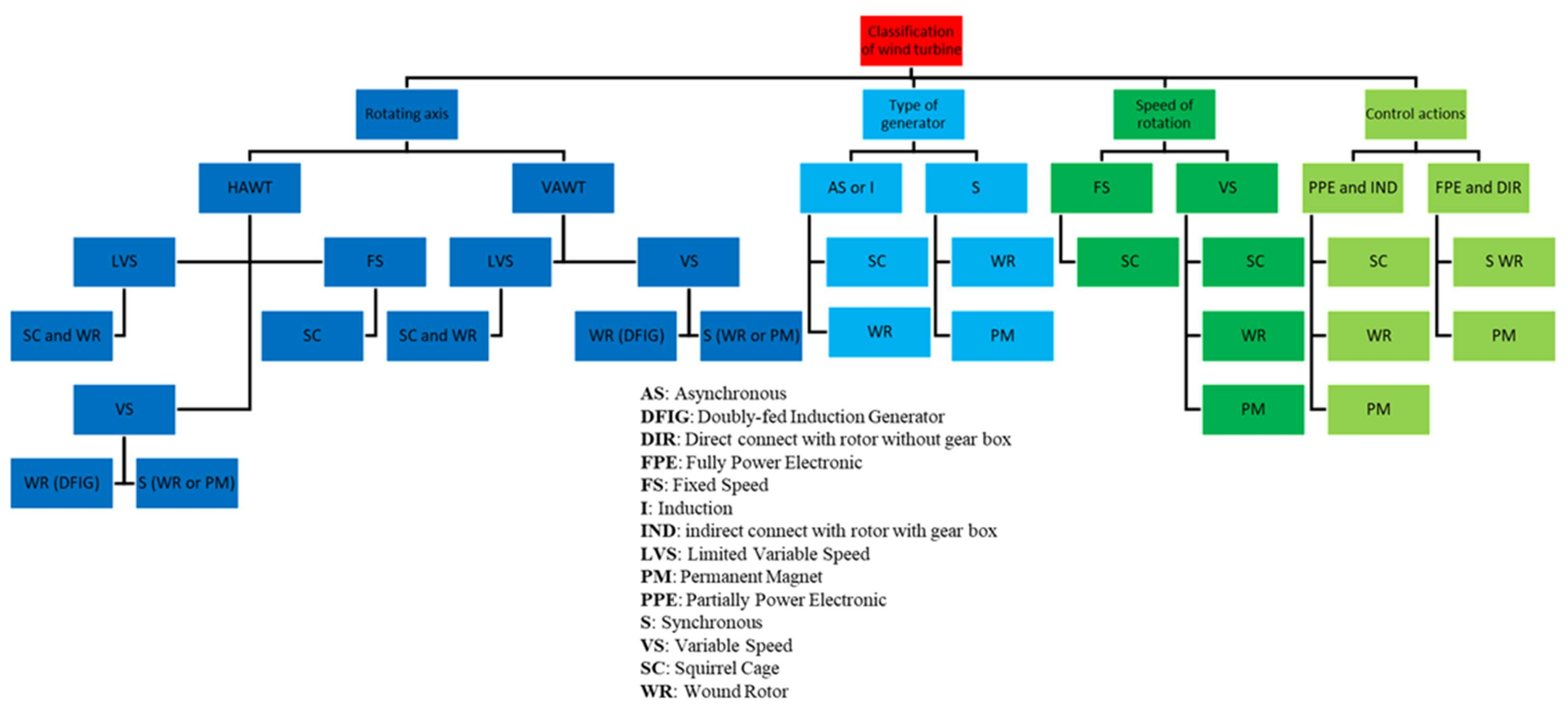
If the site accepts wind speed from one direction, then the horizontal-axis wind turbine HAWT is the best turbine type, while the vertical-axis wind turbine VAWT is the best turbine type for a site accepting wind from all directions.
2-
In addition to the VAWT accepting the wind from all directions on-site, its wind speed level and speed of rotation are less than those of HAWT.
3-
The selection of a generator type for both HAWT and VAWT is based on the condition of wind speed as follows:
(a)
If the wind speed level is fixed, then the squirrel cage induction generator (SCIG) is the best generator selection.
(b)
If the wind speed level varies narrowly or widely, then there are many options for generator selection, such as a squirrel cage, wound rotor (WR) with external resistance, or partial or full-power electronics, such as a double-fed induction generator DFIG, synchronous generator, or permanent magnet synchronous generator (PMSG).
It was further deduced that the variable speed double-feed induction generators were the commonly used type of generator for wind energy conversion systems. An energy storage system that is very efficient and reliable is also required in wind energy conversion systems. This further implies that future research work should aim at building cheaper energy storage systems to support the performance of the wind energy conversion system. The feasibility of the storage technology in terms of commercialization should equally be another key point to be considered in future investigations. The power electronics aspect of the system must also be improved and this is likely to reduce the entire cost of the technology while maintaining high performance. Similarly, the turbine components, such as blades, nacelle, etc., require further optimization in terms of the material and design to reduce the cost of the entire system.

Author Contributions

Conceptualization, A.G.O., M.A.A., T.W.; methodology, K.E., T.S., E.T.S. and K.S.H.; formal analysis, A.G.O., M.A.A., T.W.; investigation, K.E., T.S., E.T.S., and K.S.H.; resources, A.G.O., M.A.A., T.W.; data curation, K.E., T.S., E.T.S. and K.S.H.; writing—original draft preparation, A.G.O., T.W., M.A.A., K.E., T.S., E.T.S. and K.S.H.; writing—review and editing, T.W., M.A.A., K.E., A.G.O.; supervision, A.G.O., M.A.A.; project administration, T.W. All authors have read and agreed to the published version of the manuscript.

Funding

This research received no external funding.

Institutional Review Board Statement

Not applicable.

Informed Consent Statement

Not applicable.

Data Availability Statement

Not applicable.

Conflicts of Interest

The authors declare no conflict of interest.

References

  1. Zhang, Z.; Borhani, T.N.; Olabi, A.G. Status and perspective of CO2 absorption process. Energy 2020, 205, 118057. [Google Scholar] [CrossRef]
  2. Wilberforce, T.; Olabi, A.G.; Sayed, E.T.; Elsaid, K.; Abdelkareem, M.A. Progress in carbon capture technologies. Sci. Total Environ. 2020. [Google Scholar] [CrossRef]
  3. Fant, C.; Boehlert, B.; Strzepek, K.; Larsen, P.; White, A.; Gulati, S.; Li, Y.; Martinich, J. Climate change impacts and costs to U.S. electricity transmission and distribution infrastructure. Energy 2020, 195, 116899. [Google Scholar] [CrossRef]
  4. Kabayo, J.; Marques, P.; Garcia, R.; Freire, F. Life-cycle sustainability assessment of key electricity generation systems in Portugal. Energy 2019, 176, 131–142. [Google Scholar] [CrossRef]
  5. Hanif, I.; Raza, S.M.F.; Gago-de-Santos, P.; Abbas, Q. Fossil fuels, foreign direct investment, and economic growth have triggered CO2 emissions in emerging Asian economies: Some empirical evidence. Energy 2019, 171, 493–501. [Google Scholar] [CrossRef]
  6. Al-Shayji, K.; Aleisa, E. Characterizing the fossil fuel impacts in water desalination plants in Kuwait: A Life Cycle Assessment approach. Energy 2018, 158, 681–692. [Google Scholar] [CrossRef]
  7. Salameh, T.; Abdelkareem, M.A.; Olabi, A.G.; Sayed, E.T.; Al-Chaderchi, M.; Rezk, H. Integrated standalone hybrid solar PV, fuel cell and diesel generator power system for battery or supercapacitor storage systems in Khorfakkan, United Arab Emirates. Int. J. Hydrogen Energy 2020, 46, 6014–6027. [Google Scholar] [CrossRef]
  8. Olabi, A.G.; Bahri, A.s.; Abdelghafar, A.A.; Baroutaji, A.; Sayed, E.T.; Alami, A.H.; Rezk, H.; Abdelkareem, M.A. Large-scale hydrogen production and storage technologies: Current status and future directions. Int. J. Hydrogen Energy 2020. [Google Scholar] [CrossRef]
  9. Elsaid, K.; Sayed, E.T.; Yousef, B.A.A.; Rabaia, M.K.H.; Abdelkareem, M.A.; Olabi, A.G. Recent progress on the utilization of waste heat for desalination: A review. Energy Convers. Manag. 2020, 221, 113105. [Google Scholar] [CrossRef]
  10. Olabi, A.G.; Elsaid, K.; Rabaia, M.K.H.; Askalany, A.A.; Abdelkareem, M.A. Waste heat-driven desalination systems: Perspective. Energy 2020, 209, 118373. [Google Scholar] [CrossRef]
  11. Jouhara, H.; Olabi, A.G. Editorial: Industrial waste heat recovery. Energy 2018, 160, 1–2. [Google Scholar] [CrossRef]
  12. Cherif, H.; Benakcha, A.; Laib, I.; Chehaidia, S.E.; Menacer, A.; Soudan, B.; Olabi, A.G. Early detection and localization of stator inter-turn faults based on discrete wavelet energy ratio and neural networks in induction motor. Energy 2020, 212, 118684. [Google Scholar] [CrossRef]
  13. Abdelkareem, M.A.; Elsaid, K.; Wilberforce, T.; Kamil, M.; Sayed, E.T.; Olabi, A. Environmental aspects of fuel cells: A review. Sci. Total Environ. 2021, 752, 141803. [Google Scholar] [CrossRef]
  14. Fathy, A.; Elaziz, M.A.; Sayed, E.T.; Olabi, A.G.; Rezk, H. Optimal parameter identification of triple-junction photovoltaic panel based on enhanced moth search algorithm. Energy 2019, 188, 116025. [Google Scholar] [CrossRef]
  15. Tanveer, W.H.; Rezk, H.; Nassef, A.; Abdelkareem, M.A.; Kolosz, B.; Karuppasamy, K.; Aslam, J.; Gilani, S.O. Improving fuel cell performance via optimal parameters identification through fuzzy logic based-modeling and optimization. Energy 2020, 204, 117976. [Google Scholar] [CrossRef]
  16. Alami, A.H.; Abdelkareem, M.A.; Faraj, M.; Aokal, K.; Al Safarini, N. Titanium dioxide-coated nickel foam photoelectrodes for direct urea fuel cell applications. Energy 2020, 208, 118253. [Google Scholar] [CrossRef]
  17. Longa, F.D.; Nogueira, L.P.; Limberger, J.; Wees, J.-D.V.; van der Zwaan, B. Scenarios for geothermal energy deployment in Europe. Energy 2020, 206, 118060. [Google Scholar] [CrossRef]
  18. Liang, J.-D.; Huang, B.-H.; Chiang, Y.-C.; Chen, S.-L. Experimental investigation of a liquid desiccant dehumidification system integrated with shallow geothermal energy. Energy 2020, 191, 116452. [Google Scholar] [CrossRef]
  19. Da Silva, R.G.; Ribeiro, M.H.D.M.; Moreno, S.R.; Mariani, V.C.; Coelho, L.D.S. A novel decomposition-ensemble learning framework for multi-step ahead wind energy forecasting. Energy 2020, 216, 119174. [Google Scholar] [CrossRef]
  20. Siddique, M.B.; Thakur, J. Assessment of curtailed wind energy potential for off-grid applications through mobile battery storage. Energy 2020, 201, 117601. [Google Scholar] [CrossRef]
  21. Sayed, E.T.; Alawadhi, H.; Elsaid, K.; Olabi, A.G.; Almakrani, M.A.; Tamim, S.B.; Alafranji, G.; Abdelkareem, M. A Carbon-Cloth Anode Electroplated with Iron Nanostructure for Microbial Fuel Cell Operated with Real Wastewater. Sustainability 2020, 12, 6538. [Google Scholar] [CrossRef]
  22. Rodriguez, C.; Alaswad, A.; El-Hassan, Z.; Olabi, A.G. Waste paper and macroalgae co-digestion effect on methane production. Energy 2018, 154, 119–125. [Google Scholar] [CrossRef] [Green Version]
  23. Wilberforce, T.; El Hassan, Z.; Durrant, A.; Thompson, J.; Soudan, B.; Olabi, A.G. Overview of ocean power technology. Energy 2019, 175, 165–181. [Google Scholar] [CrossRef] [Green Version]
  24. Soudan, B. Community-scale baseload generation from marine energy. Energy 2019, 189, 116134. [Google Scholar] [CrossRef]
  25. Ogungbemi, E.; Ijaodola, O.; Khatib, F.; Wilberforce, T.; El Hassan, Z.; Thompson, J.; Ramadan, M.; Olabi, A. Fuel cell membranes–Pros and cons. Energy 2019, 172, 155–172. [Google Scholar] [CrossRef] [Green Version]
  26. Zhang, L.; Fu, G.; Zhang, Z. Electricity generation and microbial community in long-running microbial fuel cell for high-salinity mustard tuber wastewater treatment. Bioelectrochemistry 2019, 126, 20–28. [Google Scholar] [CrossRef] [PubMed]
  27. IEA. Data and Statistics. Available online: https://www.iea.org/data-and-statistics?country=WORLD&fuel=CO2%20emissions&indicator=CO2BySource (accessed on 3 March 2021).
  28. Rabaia, M.K.H.; Abdelkareem, M.A.; Sayed, E.T.; Elsaid, K.; Chae, K.-J.; Wilberforce, T.; Olabi, A.G. Environmental impacts of solar energy systems: A review. Sci. Total Environ. 2020, 754, 141989. [Google Scholar] [CrossRef]
  29. Abdelkareem, M.A.; Assad, M.E.H.; Sayed, E.T.; Soudan, B. Recent progress in the use of renewable energy sources to power water desalination plants. Desalination 2018, 435, 97–113. [Google Scholar] [CrossRef]
  30. Shahbaz, M.; Raghutla, C.; Chittedi, K.R.; Jiao, Z.; Vo, X.V. The effect of renewable energy consumption on economic growth: Evidence from the renewable energy country attractive index. Energy 2020, 207, 118162. [Google Scholar] [CrossRef]
  31. Olabi, A.G.; Wilberforce, T.; Abdelkareem, M.A. Fuel cell application in the automotive industry and future perspective. Energy 2021, 214, 118955. [Google Scholar] [CrossRef]
  32. Størset, S.Ø.; Tangen, G.; Berstad, D.; Eliasson, P.; Hoff, K.A.; Langørgen, Ø.; Munkejord, S.T.; Roussanaly, S.; Torsæter, M. Profiting from CCS innovations: A study to measure potential value creation from CCS research and development. Int. J. Greenh. Gas Control. 2019, 83, 208–215. [Google Scholar] [CrossRef]
  33. Shaner, M.R.; Davis, S.J.; Lewis, N.S.; Caldeira, K. Geophysical constraints on the reliability of solar and wind power in the United States. Energy Environ. Sci. 2018, 11, 914–925. [Google Scholar] [CrossRef] [Green Version]
  34. Das, S.; Ghangrekar, M. Tungsten oxide as electrocatalyst for improved power generation and wastewater treatment in microbial fuel cell. Environ. Technol. 2019, 41, 2546–2553. [Google Scholar] [CrossRef] [PubMed]
  35. IRENA. Global Renewables Outlook: Energy Transformation 2050. Available online: https://www.irena.org/publications/2020/Apr/Global-Renewables-Outlook-2020 (accessed on 2 February 2021).
  36. Bilgili, M.; Yasar, A.; Simsek, E. Offshore wind power development in Europe and its comparison with onshore counterpart. Renew. Sustain. Energy Rev. 2011, 15, 905–915. [Google Scholar] [CrossRef]
  37. Koçak, K. A method for determination of wind speed persistence and its application. Energy 2002, 27, 967–973. [Google Scholar] [CrossRef]
  38. Wood, D. Determination of the optimum tower height for a small wind turbine. Int. J. Renew. Energy Eng. 2001, 3, 356–359. [Google Scholar]
  39. Green Building. Available online: https://www.greenspec.co.uk/building-design/small-wind-turbines/ (accessed on 2 November 2020).
  40. Weisser, D. A wind energy analysis of Grenada: An estimation using the ‘Weibull’density function. Renew. Energy 2003, 28, 1803–1812. [Google Scholar] [CrossRef]
  41. Panda, R.; Sarkar, T.; Bhattacharya, A. Stochastic study of the wind-energy potential of India. Energy 1990, 15, 921–930. [Google Scholar] [CrossRef]
  42. Lambert, M.; Ogle, M.; Smith, B. Investigation of wind-induced fatigue in tall guyed steel masts. J. Wind Eng. Ind. Aerodyn. 1988, 30, 55–65. [Google Scholar] [CrossRef]
  43. Karaki, S.H.; Salim, B.A.; Chedid, R.B. Probabilistic model of a two-site wind energy conversion system. IEEE Trans. Energy Convers. 2002, 17, 530–536. [Google Scholar] [CrossRef]
  44. Jamil, M.; Parsa, S.; Majidi, M. Wind power statistics and an evaluation of wind energy density. Renew. Energy 1995, 6, 623–628. [Google Scholar] [CrossRef]
  45. Şen, Z.; Şahin, A.D. Regional assessment of wind power in western Turkey by the cumulative semivariogram method. Renew. Energy 1997, 12, 169–177. [Google Scholar] [CrossRef]
  46. Ettoumi, F.Y.; Sauvageot, H.; Adane, A.-E.-H. Statistical bivariate modelling of wind using first-order Markov chain and Weibull distribution. Renew. Energy 2003, 28, 1787–1802. [Google Scholar] [CrossRef]
  47. Torre, M.; Poggi, P.; Louche, A. Markovian model for studying wind speed time series in Corsica. Int. J. Renew. Energy Eng. 2001, 3, 311–319. [Google Scholar]
  48. Feijoo, A.E.; Cidras, J.; Dornelas, J.G. Wind speed simulation in wind farms for steady-state security assessment of electrical power systems. IEEE Trans. Energy Convers. 1999, 14, 1582–1588. [Google Scholar] [CrossRef]
  49. Ulgen, K.; Genc, A.; Hepbasli, A.; Oturanc, G. Assessment of wind characteristics for energy generation. Energy Sources 2004, 26, 1227–1237. [Google Scholar] [CrossRef]
  50. Emeis, S. Measurement of the available wind energy with sodar. Indian J. Power River Val. Dev. 2001, 51, 244–250. [Google Scholar]
  51. Yesilbudak, M.; Sagiroglu, S.; Colak, I. A wind speed forecasting approach based on 2-dimensional input space. In Proceedings of the 2012 International Conference on Renewable Energy Research and Applications (ICRERA), Nagasaki, Japan, 11–14 November 2012; IEEE: Piscataway Township, NJ, USA, 2012; pp. 1–5. [Google Scholar]
  52. Kumar, Y.; Ringenberg, J.; Depuru, S.S.; Devabhaktuni, V.K.; Lee, J.W.; Nikolaidis, E.; Andersen, B.; Afjeh, A. Wind energy: Trends and enabling technologies. Renew. Sustain. Energy Rev. 2016, 53, 209–224. [Google Scholar] [CrossRef]
  53. Kaldellis, J.K.; Zafirakis, D. The wind energy (r) evolution: A short review of a long history. Renew. Energy 2011, 36, 1887–1901. [Google Scholar] [CrossRef]
  54. Commission, W. Renewable Energy Resources: Opportunities and Constraints 1990–2020. Available online: https://inis.iaea.org/search/searchsinglerecord.aspx?recordsFor=SingleRecord&RN=28060022 (accessed on 3 March 2021).
  55. Manwell, J.; McGowan, J.; Rogers, A. Mechanics and Dynamics. In Wind Energy Explained: Theory, Design and Application; John Wiley & Sons, Ltd.: Chichester, UK, 2020; Volume 10, p. 0470846127. [Google Scholar]
  56. Sedaghat, A.; Alkhatib, F.; Eilaghi, A.; Sabati, M.; Borvayeh, L.; Mostafaeipour, A. A new strategy for wind turbine selection using optimization based on rated wind speed. Energy Procedia 2019, 160, 582–589. [Google Scholar] [CrossRef]
  57. Aho, J.; Buckspan, A.; Laks, J.; Fleming, P.; Jeong, Y.; Dunne, F.; Churchfield, M.; Pao, L.; Johnson, K. A tutorial of wind turbine control for supporting grid frequency through active power control. In Proceedings of the 2012 American Control Conference (ACC), Montreal, QC, Canada, 27–29 June 2012; IEEE: Piscataway Township, NJ, USA, 2012; pp. 3120–3131. [Google Scholar]
  58. Paulides, J.; Encica, L.; Jansen, J.; Lomonova, E.; Van Wijck, D. Small-scale urban venturi wind turbine: Direct-drive generator. In Proceedings of the 2009 IEEE International Electric Machines and Drives Conference, Miami, FL, USA, 3–6 May 2009; IEEE: Piscataway Township, NJ, USA, 2012; pp. 1368–1373. [Google Scholar]
  59. Cace, J.; Ter Horst, R.; Syngellakis, H.; Power, I. Urban wind turbines. Guid. Small Wind Turbines Built Environ. Urban−Wind. Org. 2007. Available online: http://www.urbanwind.net/pdf/SMALL_WIND_TURBINES_GUIDE_final.pdf (accessed on 5 January 2021).
  60. Ohya, Y.; Karasudani, T. A shrouded wind turbine generating high output power with wind-lens technology. Energies 2010, 3, 634–649. [Google Scholar] [CrossRef] [Green Version]
  61. Mishnaevsky, L., Jr.; Brøndsted, P.; Nijssen, R.; Lekou, D.J.; Philippidis, T.P. Materials of large wind turbine blades: Recent results in testing and modeling. Wind Energy 2012, 15, 83–97. [Google Scholar] [CrossRef]
  62. Sicot, C.; Devinant, P.; Loyer, S.; Hureau, J. Rotation and turbulence effects on a HAWT blade airfoil aerodynamics. In Wind Energy; Springer: Berlin/Heidelberg, Germany, 2007; pp. 221–226. [Google Scholar]
  63. Smith, A.; Stehly, T.; Musial, W. 2014–2015 Offshore Wind Technologies Market Report; National Renewable Energy Lab (NREL): Golden, CO, USA, 2015. [Google Scholar]
  64. Cheng, M.; Zhu, Y. The state of the art of wind energy conversion systems and technologies: A review. Energy Convers. Manag. 2014, 88, 332–347. [Google Scholar] [CrossRef]
  65. Song, S.-H.; Kang, S.-i.; Hahm, N.-k. Implementation and control of grid connected AC-DC-AC power converter for variable speed wind energy conversion system. In Proceedings of the Eighteenth Annual IEEE Applied Power Electronics Conference and Exposition, Miami Beach, FL, USA, 9–13 February 2003; APEC’03. IEEE: Piscataway Township, NJ, USA, 2012; pp. 154–158. [Google Scholar]
  66. Dutton, A.; Halliday, J.; Blanch, M. The feasibility of building-mounted/integrated wind turbines (BUWTs): Achieving their potential for carbon emission reductions. Energy Res. Unit CCLRC 2005, 77–83. Available online: https://ukerc.rl.ac.uk/pdf/BUWT_final_v004_full.pdf (accessed on 5 January 2021).
  67. Li, J.; Wang, W.-S.; Song, J.-H. Modeling And Dynamic Simulation Of Variable Speed Wind Turbine. Power Syst. Technol. 2003, 9, 14–17. [Google Scholar]
  68. Chen, Z.; Guerrero, J.M.; Blaabjerg, F. A review of the state of the art of power electronics for wind turbines. IEEE Trans. Power Electron. 2009, 24, 1859–1875. [Google Scholar] [CrossRef]
  69. Eggers, J.A.; Holley, W.; Digumarthi, R.; Chaney, K. Exploratory study of HAWT blade throw risk to nearby people and property. In Proceedings of the 20th 2001 ASME Wind Energy Symposium, Reno, NV, USA, 11–14 January 2001; p. 61. [Google Scholar]
  70. Dai, J.; Yang, X.; Hu, W.; Wen, L.; Tan, Y. Effect investigation of yaw on wind turbine performance based on SCADA data. Energy 2018, 149, 684–696. [Google Scholar] [CrossRef]
  71. U.S. Department of Energy, Office of Energy Efficiency & Renewable Energy. The Inside of a Wind Turbine. Available online: https://www.energy.gov/eere/wind/inside-wind-turbine (accessed on 2 December 2020).
  72. Eriksson, S.; Bernhoff, H.; Leijon, M. Evaluation of different turbine concepts for wind power. Renew. Sustain. Energy Rev. 2008, 12, 1419–1434. [Google Scholar] [CrossRef]
  73. Ghenai, C.; Salameh, T.; Janajreh, I. Modeling and Simulation of Shrouded Horizontal Axis Wind Turbine Using RANS Method. Jordan J. Mech. Ind. Eng. 2017, 11, 235–243. [Google Scholar]
  74. Sharikzadeh, M. Investigate the Performance of a Proposed Micro-Turbine Design in Small Scale Openings in High Rise Buildings. Master’s Thesis, The University of Arizona, Tucson, AZ, USA, 2016. Available online: https://repository.arizona.edu/handle/10150/622895 (accessed on 11 January 2021).
  75. Peacock, A.; Jenkins, D.; Ahadzi, M.; Berry, A.; Turan, S. Micro wind turbines in the UK domestic sector. Energy Build. 2008, 40, 1324–1333. [Google Scholar] [CrossRef]
  76. Trade, H. Wes Tulipo Turbine-Wind Energy Solution. Available online: https://windenergysolutions.nl/ (accessed on 15 January 2021).
  77. Goldberg, S.B. Vertical-Axis Wind Turbine with a Twisted Blade Configuration. U.S. Patanets US5405246A, 11 April 1995. [Google Scholar]
  78. van der Veen, G.J.; van Wingerden, J.-W.; Fleming, P.A.; Scholbrock, A.K.; Verhaegen, M. Global data-driven modeling of wind turbines in the presence of turbulence. Control Eng. Pract. 2013, 21, 441–454. [Google Scholar] [CrossRef]
  79. Ferrigno, K.J. Challenges and Strategies for Increasing Adoption of Small Wind Turbines in Urban Areas. Master’s Thesis, Massachusetts Institute of Technology, Cambridge, MA, USA, 2010. Available online: https://dspace.mit.edu/handle/1721.1/59240 (accessed on 21 January 2021).
  80. Paraschivoiu, I. Double-multiple streamtube model for studying vertical-axis wind turbines. J. Propuls. Power 1988, 4, 370–377. [Google Scholar] [CrossRef]
  81. Lambie, B. Aeroelastic Investigation of a Wind Turbine Airfoil with Self-Adaptive Camber. Ph.D. Thesis, Technische Universität Darmstadt, Darmstadt, Germany, 2011. Available online: http://tuprints.ulb.tu-darmstadt.de/2769/ (accessed on 21 January 2021).
  82. McGowan, R.; Lozano, R.; Raghav, V.; Komerath, N. Vertical Axis Micro Wind Turbine Design for Low Tip Speed Ratios. In Proceedings of the International Multi-Conferance on Engineering and Technology Innovation, Orlando, FL, USA, 26–31 July 2019. Available online: http://www.iiis.org/CDs2012/CD2012IMC/DEMSET_2012/PapersPdf/DC885ZU.pdf (accessed on 25 January 2021).
  83. Kirsch, J. Design of a Small Wind Turbine for Electric Power Generation (1–5kW). Bachelor’s Thesis, University of Southern Queensland, Toowoomba, Australia, 2009. Available online: https://eprints.usq.edu.au/8546/1/Kirsch_2009_MainProject_.pdf (accessed on 25 January 2021).
  84. Menet, J.-L. A double-step Savonius rotor for local production of electricity: A design study. Renew. Energy 2004, 29, 1843–1862. [Google Scholar] [CrossRef]
  85. Jin, X.; Zhao, G.; Gao, K.; Ju, W. Darrieus vertical axis wind turbine: Basic research methods. Renew. Sustain. Energy Rev. 2015, 42, 212–225. [Google Scholar] [CrossRef]
  86. Roy, S.; Saha, U.K. Wind tunnel experiments of a newly developed two-bladed Savonius-style wind turbine. Appl. Energy 2015, 137, 117–125. [Google Scholar] [CrossRef]
  87. Roy, S.; Saha, U.K. Computational study to assess the influence of overlap ratio on static torque characteristics of a vertical axis wind turbine. Procedia Eng. 2013, 51, 694–702. [Google Scholar] [CrossRef] [Green Version]
  88. Wenehenubun, F.; Saputra, A.; Sutanto, H. An Experimental Study on the Performance of Savonius Wind Turbines Related With The Number Of Blades. Energy Procedia 2015, 68, 297–304. [Google Scholar] [CrossRef] [Green Version]
  89. Wang, Y.; Sun, X.; Dong, X.; Zhu, B.; Huang, D.; Zheng, Z. Numerical investigation on aerodynamic performance of a novel vertical axis wind turbine with adaptive blades. Energy Convers. Manag. 2016, 108, 275–286. [Google Scholar] [CrossRef]
  90. Kim, S.; Cheong, C. Development of low-noise drag-type vertical wind turbines. Renew. Energy 2015, 79, 199–208. [Google Scholar] [CrossRef]
  91. Akwa, J.V.; Vielmo, H.A.; Petry, A.P. A review on the performance of Savonius wind turbines. Renew. Sustain. Energy Rev. 2012, 16, 3054–3064. [Google Scholar] [CrossRef]
  92. Shah, S. Small Scale Vertical Axis Wind Turbine. Master’s Thesis, Ryerson University, Toronto, ON, Canada, 2014. Available online: http://digital.library.ryerson.ca/islandora/object/RULA%3A4280/datastream/OBJ/vie (accessed on 5 November 2020).
  93. Musgrove, P.J. Energy from Wind in Rural and Urban Communities. In Passive and Low Energy Ecotechniques; Bowen, A., Ed.; Pergamon: Oxford, UK, 1985; pp. 290–309. [Google Scholar] [CrossRef]
  94. Musgrove, P.J. Wind energy conversion: Recent progress and future prospects. Sol. Wind Technol. 1987, 4, 37–49. [Google Scholar] [CrossRef]
  95. Tjiu, W.; Marnoto, T.; Mat, S.; Ruslan, M.H.; Sopian, K. Darrieus vertical axis wind turbine for power generation I: Assessment of Darrieus VAWT configurations. Renew. Energy 2015, 75, 50–67. [Google Scholar] [CrossRef]
  96. Yaw System. Available online: https://en.wikipedia.org/wiki/Yaw_system (accessed on 29 January 2021).
  97. Wind Turbine Design. Available online: https://en.wikipedia.org/wiki/Wind_turbine_design (accessed on 29 January 2021).
  98. Mishnaevsky, L.; Branner, K.; Petersen, H.N.; Beauson, J.; McGugan, M.; Sørensen, B.F. Materials for Wind Turbine Blades: An Overview. Materials 2017, 10, 1285. [Google Scholar] [CrossRef] [PubMed] [Green Version]
  99. Oyague, F. GRC Drive Train Round Robin GRC 750/48.2 Loading Document (IEC 61400-1 Class IIB); National Renewable Energy Lab. (NREL): Golden, CO, USA, 2009. Available online: https://www.osti.gov/biblio/1030848 (accessed on 29 January 2021).
  100. Watson, J.C.; Serrano, J.C. Composite materials for wind blades. Wind Syst. 2010, 46–51. Available online: https://www.windsystemsmag.com/composite-materials-for-wind-blades/ (accessed on 29 January 2021).
  101. Gentry, T.R.; Al-Haddad, T.; Bank, L.C.; Arias, F.R.; Nagle, A.; Leahy, P. Structural Analysis of a Roof Extracted from a Wind Turbine Blade. J. Archit. Eng. 2020, 26, 04020040. [Google Scholar] [CrossRef]
  102. Dalala, Z.M.; Zahid, Z.U.; Yu, W.; Cho, Y.; Lai, J.-S.J. Design and analysis of an MPPT technique for small-scale wind energy conversion systems. IEEE Trans. Energy Convers. 2013, 28, 756–767. [Google Scholar] [CrossRef]
  103. Devashish, T.A. A Comprehesive Review on Wind Energy System for Electric Power Generation: Current Situation And Improved Technologies to Realize Future Development. Int. J. Renew. Energy Res. 2017, 7, 1786–1805. [Google Scholar]
  104. Burton, T.; Sharpe, D.; Jenkins, N.; Bossanyi, E. Wind Energy Handbook; Wiley Online Library: Hoboken, NJ, USA, 2001; Volume 2. [Google Scholar]
  105. Silva, C.E.A.; Oliveira, D.S.; Barreto, L.H.S.C.; Bascopé, R.P.T. A novel three-phase rectifier with high power factor for wind energy conversion systems. In Proceedings of the 2009 Brazilian Power Electronics Conference, Gramado, Brazil, 27 September–1 October 2009; pp. 985–992. [Google Scholar]
  106. Hyong Sik, K.; Dah-Chuan, L.D. Wind energy conversion system from electrical perspective—A survey. Smart Grid Renew. Energy 2010, 1, 119–131. Available online: https://www.scirp.org/html/2-6401031_3324.htm (accessed on 29 January 2021).
  107. Geng, H.; Xu, D. Stability analysis and improvements for variable-speed multipole permanent magnet synchronous generator-based wind energy conversion system. IEEE Trans. Sustain. Energy 2011, 2, 459–467. [Google Scholar] [CrossRef]
  108. Polinder, H.; Van der Pijl, F.F.; De Vilder, G.-J.; Tavner, P.J. Comparison of direct-drive and geared generator concepts for wind turbines. IEEE Trans. Energy Convers. 2006, 21, 725–733. [Google Scholar] [CrossRef] [Green Version]
  109. Do Nascimento, C.S.; Filho, A.F.F. Design of an induction generator with copper squirrel cage rotor and asymetric slots. In Proceedings of the 2014 International Conference on Renewable Energy Research and Application (ICRERA), Milwaukee, WI, USA, 19–22 October 2014; pp. 544–549. [Google Scholar]
  110. Farret, F.A.; Simoes, M.G. Integration of Alternative Sources of Energy; John Wiley & Sons: Hoboken, NJ, USA, 2006. [Google Scholar]
  111. Murthy, S.; Malik, O.; Tandon, A. Analysis of self-excited induction generators. IEE Proc. Gene. Trans. Distrib. 1982, 129, 260–265. Available online: https://ieeexplore.ieee.org/document/4643536/ (accessed on 2 February 2021).
  112. Tandon, A.; Murthy, S.; Berg, G. Steady state analysis of capacitor self-excited induction generators. IEEE Trans. Power Appar. Syst. 1984, 103, 612–618. [Google Scholar] [CrossRef]
  113. Harrouz, A.; Colak, I.; Kayisli, K. Control of a small wind turbine system application. In Proceedings of the 2016 IEEE International Conference on Renewable Energy Research and Applications (ICRERA), Birmingham, UK, 20–23 November 2016; IEEE: Piscataway Township, NJ, USA, 2012; pp. 1128–1133. [Google Scholar]
  114. Blaabjerg, F.; Liserre, M.; Ma, K. Power electronics converters for wind turbine systems. IEEE Trans. Ind. Appl. 2011, 48, 708–719. [Google Scholar] [CrossRef] [Green Version]
  115. Bhende, C.; Mishra, S.; Malla, S.G. Permanent magnet synchronous generator-based standalone wind energy supply system. IEEE Trans. Sustain. Energy 2011, 2, 361–373. [Google Scholar] [CrossRef]
  116. Qiao, W.; Yang, X.; Gong, X. Wind speed and rotor position sensorless control for direct-drive PMG wind turbines. IEEE Trans. Ind. Appl. 2011, 48, 3–11. [Google Scholar] [CrossRef]
  117. Qiao, W.; Qu, L.; Harley, R.G. Control of IPM synchronous generator for maximum wind power generation considering magnetic saturation. IEEE Trans. Ind. Appl. 2009, 45, 1095–1105. [Google Scholar] [CrossRef] [Green Version]
  118. Barote, L.; Marinescu, C.; Cirstea, M.N. Control structure for single-phase stand-alone wind-based energy sources. IEEE Trans. Ind. Electron. 2012, 60, 764–772. [Google Scholar] [CrossRef]
  119. Blaabjerg, F.; Ma, K. Future on power electronics for wind turbine systems. IEEE J. Emerg. Sel. Top. Power Electron. 2013, 1, 139–152. [Google Scholar] [CrossRef]
  120. Venkataraman, A.; Maswood, A.I.; Rahman, S.N.; Gabriel, O.H. A novel maximum power point tracking algorithm for a stand-alone unity power factor wind energy conversion system. In Proceedings of the 2013 International Conference on Renewable Energy Research and Applications (ICRERA), Madrid, Spain, 20–23 October 2013; IEEE: Piscataway Township, NJ, USA, 2012; pp. 109–114. [Google Scholar]
  121. Nakanishi, T.; Orikawa, K.; Itoh, J.-I. Modular Multilevel Converter for wind power generation system connected to micro-grid. In Proceedings of the 2014 International Conference on Renewable Energy Research and Application (ICRERA), Milwaukee, WI, USA, 19–22 October 2014; pp. 653–658. [Google Scholar]
  122. Yao, J.; Li, H.; Liao, Y.; Chen, Z. An improved control strategy of limiting the DC-link voltage fluctuation for a doubly fed induction wind generator. IEEE Trans. Power Electron. 2008, 23, 1205–1213. [Google Scholar]
  123. Grabic, S.; Celanovic, N.; Katic, V.A. Permanent magnet synchronous generator cascade for wind turbine application. IEEE Trans. Power Electron. 2008, 23, 1136–1142. [Google Scholar] [CrossRef]
  124. Dai, J.; Xu, D.; Wu, B. A novel control scheme for current-source-converter-based PMSG wind energy conversion systems. IEEE Trans. Power Electron. 2009, 24, 963–972. [Google Scholar]
  125. Abdelsalam, I.; Adam, G.P.; Holliday, D.; Williams, B.W. Modified back-to-back current source converter and its application to wind energy conversion systems. IET Power Electron. 2014, 8, 103–111. [Google Scholar] [CrossRef] [Green Version]
  126. Sarja, J.; Halonen, V. Wind turbine selection criteria: A customer perspective. J. Energy Power Eng. 2013, 7, 1795. [Google Scholar]
  127. Perkin, S.; Garrett, D.; Jensson, P. Optimal wind turbine selection methodology: A case-study for Búrfell, Iceland. Renew. Energy 2015, 75, 165–172. [Google Scholar] [CrossRef]
  128. Nemes, C.; Munteanu, F. Optimal selection of wind turbine for a specific area. In Proceedings of the 2010 12th International Conference on Optimization of Electrical and Electronic Equipment, Brasov, Romania, 20–22 May 2010; pp. 1224–1229. [Google Scholar]
  129. Chowdhury, S.; Zhang, J.; Messac, A.; Castillo, L. Optimizing the arrangement and the selection of turbines for wind farms subject to varying wind conditions. Renew. Energy 2013, 52, 273–282. [Google Scholar] [CrossRef]
  130. Fotuhi-Firuzabad, M.; Dobakhshari, A.S. Reliability-based selection of wind turbines for large-scale wind Farms. World Acad. Sci. Eng. Technol. 2009, 49, 734–740. [Google Scholar]
  131. Bencherif, M.; Brahmi, B.; Chikhaoui, A. Optimum selection of wind turbines. Sci. J. Energy Eng. 2014, 2, 36. [Google Scholar] [CrossRef] [Green Version]
  132. Montoya, F.G.; Manzano-Agugliaro, F.; López-Márquez, S.; Hernández-Escobedo, Q.; Gil, C. Wind turbine selection for wind farm layout using multi-objective evolutionary algorithms. Expert Syst. Appl. 2014, 41, 6585–6595. [Google Scholar] [CrossRef]
  133. Chowdhury, S.; Mehmani, A.; Zhang, J.; Messac, A. Market suitability and performance tradeoffs offered by commercial wind turbines across differing wind regimes. Energies 2016, 9, 352. [Google Scholar] [CrossRef] [Green Version]
  134. Martin, K.A.; Schmidt, M.F.; Shelton, S.V.; Stewart, S.W. Site Specific Optimization of Rotor/Generator Sizing of Wind Turbines. Proceeding of the ASME 2007 Energy Sustainability Conferance, Long Beach, CA, USA, 27–30 July 2007; pp. 1123–1130. Available online: https://asmedigitalcollection.asme.org/ES/proceedings-abstract/ES2007/47977/1123/329211 (accessed on 5 February 2021).
  135. Bekele, A.; Ramayya, A.V. Site Specific Design Optimization of Horizontal Axis Wind Turbine Based on Minimum Cost of Energy for Adama I Wind Farm. Int. J. Eng. Res. Technol. 2013, 2, 862–870. Available online: https://www.ijert.org/site-specific-design-optimization-of-horizontal-axis-wind-turbine-based-on-minimum-cost-of-energy-for-adama-i-wind-farm (accessed on 5 February 2021).
  136. Helgason, K. Selecting Optimum Location and Type of Wind Turbines in ICELAND. Master’s Thesis, Reykjavík University, Reykjavík, Iceland, 2012. Available online: https://skemman.is/bitstream/1946/12679/1/MScKristbjornHelgason.pdf (accessed on 5 February 2021).
  137. Eke, G.; Onyewudiala, J. Optimization of wind turbine blades using genetic algorithm. Glob. J. Res. Eng. 2010, 10, 22–26. [Google Scholar]
  138. Jureczko, M.; Pawlak, M.; Mężyk, A. Optimisation of wind turbine blades. J. Mater. Process. Technol. 2005, 167, 463–471. [Google Scholar] [CrossRef]
  139. Jowder, F.A. Wind power analysis and site matching of wind turbine generators in Kingdom of Bahrain. Appl. Energy 2009, 86, 538–545. [Google Scholar] [CrossRef]
  140. El-Shimy, M. Optimal site matching of wind turbine generator: Case study of the Gulf of Suez region in Egypt. Renew. Energy 2010, 35, 1870–1878. [Google Scholar] [CrossRef]
  141. Abul’Wafa, A.R. Matching wind turbine generators with wind regime in Egypt. Electr. Power Syst. Res. 2011, 81, 894–898. [Google Scholar] [CrossRef]
  142. Dong, Y.; Wang, J.; Jiang, H.; Shi, X. Intelligent optimized wind resource assessment and wind turbines selection in Huitengxile of Inner Mongolia, China. Appl. Energy 2013, 109, 239–253. [Google Scholar] [CrossRef]
  143. Shirgholami, Z.; Zangeneh, S.N.; Bortolini, M. Decision system to support the practitioners in the wind farm design: A case study for Iran mainland. Sustain. Energy Technol. Assess. 2016, 16, 1–10. [Google Scholar] [CrossRef]
  144. Gass, S.; Saaty, T. The computational algorithm for the parametric objective function. Nav. Res. Logist. Q. 1955, 2, 39–45. [Google Scholar] [CrossRef]
  145. Bagočius, V.; Zavadskas, E.K.; Turskis, Z. Multi-person selection of the best wind turbine based on the multi-criteria integrated additive-multiplicative utility function. J. Civ. Eng. Manag. 2014, 20, 590–599. [Google Scholar] [CrossRef]
  146. Lee, A.H.; Hung, M.-C.; Kang, H.-Y.; Pearn, W. A wind turbine evaluation model under a multi-criteria decision making environment. Energy Convers. Manag. 2012, 64, 289–300. [Google Scholar] [CrossRef]
  147. Mone, C.; Stehly, T.; Maples, B.; Settle, E. Cost of Wind Energy Review. Technical Report NREL/TP-6A20-64281; National Renewable Energy Laboratory, October 2015. Available online: https://www.nrel.gov/docs/fy21osti/78471.pdf (accessed on 1 March 2021).
  148. Lantz, E. Clean Energy Manufacturing: US Competitiveness and State Policy Strategies (Presentation); National Renewable Energy Lab.(NREL): Golden, CO, USA, 2014. [Google Scholar]
  149. Mandell, J.F.; Samborsky, D.D.; Agastra, P.; Sears, A.T.; Wilson, T.J. Analysis of SNL/MSU/DOE Fatigue Database Trends for Wind Turbine Blade Materials Sandia National Laboratories (SNL), Albuquerque, NM, and Livermore, CA, USA. 2010. Available online: https://www.osti.gov/biblio/1034894-analysis-snl-msu-doe-fatigue-database-trends-wind-turbine-blade-materials (accessed on 1 March 2021).
  150. Riddle, T.; Cairns, D.; Nelson, J.; Workman, J. Effects of defects: Part A-Development of a protocol for defect risk management & improved reliability of composite structures. In Proceedings of the 53rd AIAA/ASME/ASCE/AHS/ASC Structures, Structural Dynamics and Materials Conference 20th AIAA/ASME/AHS Adaptive Structures Conference 14th AIAA, Honolulu, HI, USA, 23–26 April 2012; p. 1420. [Google Scholar]
  151. Woo, K.; Nelson, J.; Cairns, D.; Riddle, T. Effects of Defects: Part B—Progressive Damage Modeling of Fiberglass/Epoxy Composite Structures with Manufacturing Induced Flaws Utilizing Cohesive Zone Elements. In Proceedings of the 54th AIAA/ASME/ASCE/AHS/ASC Structures, Structural Dynamics, and Materials Conference, Boston, MA, USA, 8–11 April 2013; p. 1628. [Google Scholar]
  152. Lambert, J.; Chambers, A.; Sinclair, I.; Spearing, S. 3D damage characterisation and the role of voids in the fatigue of wind turbine blade materials. Compos. Sci. Technol. 2012, 72, 337–343. [Google Scholar] [CrossRef]
  153. Zhou, H.; Dou, H.; Qin, L.; Chen, Y.; Ni, Y.; Ko, J. A review of full-scale structural testing of wind turbine blades. Renew. Sustain. Energy Rev. 2014, 33, 177–187. [Google Scholar] [CrossRef]
  154. Wiser, R.; Bolinger, M.; Barbose, G.; Darghouth, N.; Hoen, B.; Mills, A.; Rand, J.; Millstein, D.; Porter, K.; Widiss, R. Wind Technologies Market Report, Lawrence Berkeley National Laboratory. 2020. Available online: https://emp.lbl.gov/wind-technologies-market-report (accessed on 1 March 2021).
  155. Nati, G.; Kotsonis, M.; Ghaemi, S.; Scarano, F. Control of vortex shedding from a blunt trailing edge using plasma actuators. Exp. Therm. Fluid Sci. 2013, 46, 199–210. [Google Scholar] [CrossRef]
  156. Oerlemans, S.; Fisher, M.; Maeder, T.; Kögler, K. Reduction of wind turbine noise using optimized airfoils and trailing-edge serrations. AIAA J. 2009, 47, 1470–1481. [Google Scholar] [CrossRef]
  157. Wolf, A.; Lutz, T.; Würz, W.; Krämer, E.; Stalnov, O.; Seifert, A. Trailing edge noise reduction of wind turbine blades by active flow control. Wind Energy 2015, 18, 909–923. [Google Scholar] [CrossRef]
  158. Loth, E.; Steele, A.; Qin, C.; Ichter, B.; Selig, M.S.; Moriarty, P. Downwind pre-aligned rotors for extreme-scale wind turbines. Wind Energy 2017, 20, 1241–1259. [Google Scholar] [CrossRef]
  159. Willis, D.; Niezrecki, C.; Kuchma, D.; Hines, E.; Arwade, S.; Barthelmie, R.; DiPaola, M.; Drane, P.; Hansen, C.; Inalpolat, M. Wind energy research: State-of-the-art and future research directions. Renew. Energy 2018, 125, 133–154. [Google Scholar] [CrossRef]
  160. Watson, S.; Moro, A.; Reis, V.; Baniotopoulos, C.; Barth, S.; Bartoli, G.; Bauer, F.; Boelman, E.; Bosse, D.; Cherubini, A. Future emerging technologies in the wind power sector: A European perspective. Renew. Sustain. Energy Rev. 2019, 113, 109270. [Google Scholar] [CrossRef]
  161. Pastine, S. Can epoxy composites be made 100% recyclable? Reinf. Plast. 2012, 56, 26–28. [Google Scholar] [CrossRef]
  162. Beauson, J.; Lilholt, H.; Brøndsted, P. Recycling solid residues recovered from glass fibre-reinforced composites—A review applied to wind turbine blade materials. J. Reinf. Plast. Compos. 2014, 33, 1542–1556. [Google Scholar] [CrossRef]
  163. Witik, R.A.; Teuscher, R.; Michaud, V.; Ludwig, C.; Månson, J.-A.E. Carbon fibre reinforced composite waste: An environmental assessment of recycling, energy recovery and landfilling. Compos. Part A Appl. Sci. Manuf. 2013, 49, 89–99. [Google Scholar] [CrossRef]
  164. Wei, K.; Arwade, S.; Myers, A.; Hallowell, S.; Hajjar, J.; Hines, E.; Pang, W. Toward performance-based evaluation for offshore wind turbine jacket support structures. Renew. Energy 2016, 97, 709–721. [Google Scholar] [CrossRef] [Green Version]
  165. Hallowell, S.; Myers, A. Site-specific variability of load extremes of offshore wind turbines exposed to hurricane risk and breaking waves. Wind Energy 2017, 20, 143–157. [Google Scholar] [CrossRef]
  166. Wei, K.; Arwade, S.R.; Myers, A.T.; Valamanesh, V. Directional effects on the reliability of non-axisymmetric support structures for offshore wind turbines under extreme wind and wave loadings. Eng. Struct. 2016, 106, 68–79. [Google Scholar] [CrossRef] [Green Version]
  167. Valamanesh, V.; Myers, A.; Arwade, S. Multivariate analysis of extreme metocean conditions for offshore wind turbines. Struct. Saf. 2015, 55, 60–69. [Google Scholar] [CrossRef]
  168. Crossley, R.; Schubel, P.J. Wind turbine blade design. Energies 2012, 5, 3425–3449. [Google Scholar]
  169. Ibrahim, H.; Ghandour, M.; Dimitrova, M.; Ilinca, A.; Perron, J. Integration of wind energy into electricity systems: Technical challenges and actual solutions. Energy Procedia 2011, 6, 815–824. [Google Scholar] [CrossRef] [Green Version]
  170. Olabi, A.G.; Wilberforce, T.; Abdelkareem, M.A.; Ramadan, M. Critical Review of Flywheel Energy Storage System. Energies 2021, 14, 2159. [Google Scholar] [CrossRef]
  171. Alami, A.H. Flywheel Storage Systems. In Mechanical Energy Storage for Renewable and Sustainable Energy Resources; Springer IEEE: Piscataway Township, NJ, USA, 2012; pp. 35–49. [Google Scholar] [CrossRef]
  172. Olabi, A.G.; Wilberforce, T.; Ramadan, M.; Abdelkareem, M.A.; Alami, A.H. Compressed air energy storage systems: Components and operating parameters–A review. J. Energy Storage 2021, 34, 102000. [Google Scholar] [CrossRef]
  173. Alami, A.H. Compressed-Air Energy Storage Systems. In Mechanical Energy Storage for Renewable and Sustainable Energy Resources; Springer International Publishing: Cham, Switzerland, 2020; pp. 67–85. [Google Scholar] [CrossRef]
  174. Olabi, A.G.; Onumaegbu, C.; Wilberforce, T.; Ramadan, M.; Abdelkareem, M.A.; Al–Alami, A.H. Critical review of energy storage systems. Energy 2021, 214, 118987. [Google Scholar] [CrossRef]
  175. Shao, Y.; El-Kady, M.F.; Sun, J.; Li, Y.; Zhang, Q.; Zhu, M.; Wang, H.; Dunn, B.; Kaner, R.B. Design and Mechanisms of Asymmetric Supercapacitors. Chem. Rev. 2018, 118, 9233–9280. [Google Scholar] [CrossRef]
  176. Muzaffar, A.; Ahamed, M.B.; Deshmukh, K.; Thirumalai, J. A review on recent advances in hybrid supercapacitors: Design, fabrication and applications. Renew. Sustain. Energy Rev. 2019, 101, 123–145. [Google Scholar] [CrossRef]
  177. Rezk, H.; Sayed, E.T.; Al-Dhaifallah, M.; Obaid, M.; El-Sayed, A.H.M.; Abdelkareem, M.A.; Olabi, A.G. Fuel cell as an effective energy storage in reverse osmosis desalination plant powered by photovoltaic system. Energy 2019, 175, 423–433. [Google Scholar] [CrossRef] [Green Version]
  178. Olabi, A.G.; Adil, M.; Sayed, E.T.; Iqbal, A.; Rodriguez, C.; Abdelkareem, M.A. Lithium-Ion Batteries. In Reference Module in Materials Science and Materials Engineering; Elsevier: Amsterdam, The Netherlands, 2021. [Google Scholar] [CrossRef]
  179. Kim, T.; Song, W.; Son, D.-Y.; Ono, L.K.; Qi, Y. Lithium-ion batteries: Outlook on present, future, and hybridized technologies. J. Mater. Chem. A 2019, 7, 2942–2964. [Google Scholar] [CrossRef]
  180. Leahy, M.J.; Connolly, D.; Buckley, D.N. Wind Energy Storage Technologies; WIT Press: Southampton, UK, 2009; p. 661. [Google Scholar]
  181. Brekken, T.K.; Yokochi, A.; Von Jouanne, A.; Yen, Z.Z.; Hapke, H.M.; Halamay, D.A. Optimal energy storage sizing and control for wind power applications. IEEE Trans. Sustain. Energy 2010, 2, 69–77. [Google Scholar] [CrossRef]
  182. Teleke, S.; Baran, M.E.; Huang, A.Q.; Bhattacharya, S.; Anderson, L. Control strategies for battery energy storage for wind farm dispatching. IEEE Trans. Energy Convers. 2009, 24, 725–732. [Google Scholar] [CrossRef]
  183. Luo, X.; Wang, J.; Dooner, M.; Clarke, J. Overview of current development in electrical energy storage technologies and the application potential in power system operation. Appl. Energy 2015, 137, 511–536. [Google Scholar] [CrossRef] [Green Version]
  184. Chen, H.; Cong, T.N.; Yang, W.; Tan, C.; Li, Y.; Ding, Y. Progress in electrical energy storage system: A critical review. Prog. Nat. Sci. 2009, 19, 291–312. [Google Scholar] [CrossRef]
  185. Gee, A.M.; Robinson, F.V.; Dunn, R.W. Analysis of battery lifetime extension in a small-scale wind-energy system using supercapacitors. IEEE Trans. Energy Convers. 2013, 28, 24–33. [Google Scholar] [CrossRef]
Figure 1. Global carbon emissions by energy source from 1990 to 2018 (data from [27]).
Energies 14 03244 g001
Figure 2. Installed electricity capacity of different renewable energy resources in 2000 and 2018 (data from [35]).
Energies 14 03244 g002
Figure 3. Electricity generation (top) and installed capacity (bottom) of different energy sources from 2017 to 2050 [35].
Energies 14 03244 g003
Figure 4. Comparing various site locations for the installation of a wind farm [39].
Energies 14 03244 g004
Figure 5. Classifications of wind turbines.
Energies 14 03244 g005
Figure 6. The various components of a wind turbine [71].
Energies 14 03244 g006
Figure 7. Various orientations of horizontal axis wind turbines: (a) Swift type; (b) Eclectic type; (c) Fortis Montana; (d) Scirocco; (e) Tulip; (f-i) Energy ball; (f-ii) Wind wall [74].
Energies 14 03244 g007
Figure 8. Savonius wind turbine.
Energies 14 03244 g008
Figure 9. Types of Savonius blades and their turbine rotational speed [92].
Energies 14 03244 g009
Figure 10. Darrieus turbine blade design [85].
Energies 14 03244 g010
Figure 11. Types of Darrieus turbine blades: (a) Turby; (b) Windside; (c) Ropatec; (d) Gorlov helical [74].
Energies 14 03244 g011
Figure 12. Historical timeline of the Darrieus wind turbine [95].
Energies 14 03244 g012
Figure 13. Major components of a wind turbine (adapted from [96,97]).
Energies 14 03244 g013
Figure 14. Wind turbine drive-train mechanism [99].
Energies 14 03244 g014
Figure 15. Wind turbine blades [101].
Energies 14 03244 g015
Figure 16. Sectional view of a wind turbine blade [98].
Energies 14 03244 g016
Figure 17. The effect of the tip speed ratio TSR (λ) on the power coefficient at a different pitch angle [103].
Energies 14 03244 g017
Figure 18. The power coefficient as a function of the tip speed ratio (λ) and the number of blades [104].
Energies 14 03244 g018
Figure 19. Wind turbine conversion systems [106].
Energies 14 03244 g019
Figure 20. Power electronics converters for different types of generators: (1) induction (IG); (2) synchronous (SG), (a) fixed-speed squirrel-cage (SC), (b) limited variable-speed wound rotor (WR), (c) variable-speed squirrel-cage (SC), (d) variable-speed wound rotor (WR) or doubly fed (DF), (e) variable-speed indirect permanent magnet (PM), (f) variable-speed direct external excitation permanent magnet (EEPM), and (g) variable speed indirect permanent magnet (PM) with full-power electronics facilities (adapted from [64]).
Energies 14 03244 g020
Figure 21. Correlation between the mass, cost, and power produced of a wind turbine. The trends in recent times are denoted in solid lines, whiles the dotted lines are projected values [159].
Energies 14 03244 g021
Figure 22. Structures for the Block Island wind farm [159].
Energies 14 03244 g022
Table 1. Types of horizontal axis wind turbines (HAWTs) [75,76].
HAWT TypeCharacteristicsApplication
SwiftTend to have smaller blades with a ring around them to limit any form of vibration and noise.Suitable for cities and urban environments.
Eclecticsuitable for low wind velocity, hence generating energy even at unfavorable locations.Low weight, making it easy for them to be attached to structures in urban areas.
Fortis MontanaNo noise during operation even at 50 m closer to the turbine.Due to the compact size, they are useful for generating electricity for domestic purposes.
SciroccoUse similar characteristics of large turbines like varying pitch blades and the application of optimized two-rotor blades during their operation. Cheap and can produce a high amount of energy even at low wind velocity.
TulipoFixed blades with less periodic maintenance requirements.
Suitable for low wind speed.
Low vibration or noise produced.
Higher electrical energy can be generated even at low wind speed.
Publisher’s Note: MDPI stays neutral with regard to jurisdictional claims in published maps and institutional affiliations.

