Abstract
This paper presents the obtained results of experimental tests and modelling of lightning disturbances that were propagated in a model of aircraft cable bundle and caused by multiple lightning return-strokes interactions. The work is a continuation of previous research, which was concerned mainly with the interaction of lightning discharge with a single return-stroke. The section of the cable harness arranged above the metal plate was investigated. In one of its wires, a multiple-stroke current representing indirect lightning effects was injected from an impulse current generator dedicated to avionics immunity tests. Overvoltages induced at the ends of other wires surrounded by a braided shield, as well as the influence of line parameters and shield grounding condition on the shape and level of observed transients, were examined. The computer simulation results match the measurement data with satisfactory accuracy, and therefore, the presented model can be used to estimate indirect lightning effects in the wiring harness of avionics.
1. Introduction
Dangerous overvoltages and currents in on-board aircraft systems can occur due to lightning discharge striking directly to the airframe or in its vicinity [1,2,3]. These phenomena caused by the lightning electromagnetic impulse (LEMP) are called indirect effects. There are several ways for the lightning discharge to interact with the electrical and electronic aircraft installations. Among them, we can indicate the voltage drop along the airframe, inductive or capacitive coupling of cables with the LEMP or cross coupling between cables. Electromagnetic disturbances can pass through apertures and components with low shielding capacity or can be transmitted by cross coupling between wires.
Among other things, the purpose of research in this area is to determine the expected levels and shapes of lightning transients and the required immunity level of devices installed in specific zones of the aircraft [4,5]. Knowledge of phenomena occurring in installation in the presence of the atmospheric disturbances allows for the proposal of a suitable solution for minimizing the induced transients [6,7]. Computer simulations and experimental tests are used to optimize the parameters of cable lines and their routing. A well-known way to reduce interference is to use wire shielding. The effectiveness of this solution depends primarily on the method of grounding its ends [8].
The issue of the impact of the wiring harness parameters, its termination and its shielding on the observed surges was discussed in detail in our previous work [9]. In this paper, experimental tests were performed using the impulse current generator that can simulate indirect effects of the lightning with multiple return strokes. A model of the analyzed system was proposed and obtained registrations were compared with the computer simulations.
2. Cable Crosstalk
Crosstalk is a phenomenon by which a signal transmitted in one circuit affects another one, causing unwanted effects. It may be related to capacitive or inductive coupling between adjacent conductors. Figure 1 shows an example of inductive and capacitive coupling between two wires, each referenced to the ground plane. Wire 1 is the generator wire supplied from voltage source UGEN (with internal source resistance RGEN) and terminated with load resistance RL. C1 and C2 are capacitances between conductors and ground; CM is the mutual capacitance between wire 1 and wire 2. LR and LGEN are self-inductances of wires, and M is the mutual inductance between two wires. Wire 2 is the receptor terminated on both sides by resistors RNE and RFE. Indexes NE and FE specify the “near end” and “far end”, respectively. Generator current IGEN flowing in wire 1 (aggressor) and voltage UG along the wire 1 will induce current IR and voltage UR associated with the wire 2 (victim). Total cable length is denoted by X.
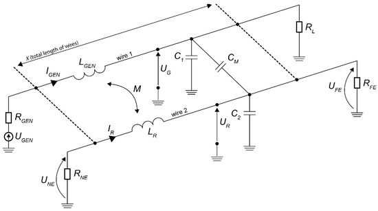
Figure 1.
Example of inductive and capacitive coupling between two wires.
The equivalent circuit of transmission line shown in Figure 1 can be described by Equations (1)–(4) in the time domain with assumptions made in [10]
All self-capacitances, self-inductances, mutual capacitances and mutual inductances can be calculated and simplified in homogeneous medium as in [11]
where h is the height of wires above the ground, r their radius, d the distance between them, µ0 the permeability of the free space and v is the velocity of propagation in free space.
When wire length is relatively short compared to the wave length (X<<λ), ignoring self-capacitance and self-inductances of wires, near end crosstalk (NEXT) and far end crosstalk (FEXT) can be calculated in the frequency domain with use of Equations (11) and (12), respectively [10]
3. Shielded Wires
Shielding is one of the methods to protect electronic interfaces against sources of electromagnetic disturbances, such as indirect effects of lightning. Cable braided shield performance depends on many parameters, the impact of which is constantly studied [12,13,14]. Figure 2 shows the equivalent circuit for capacitive coupling in a shielded cable. The shield acts as a Faraday cage, hence both mutual capacitance between generator wire and receptor wire, and self-capacitance of receptor wire, are equal to zero and are not shown in the Figure 2. CGS is a mutual capacitance between generator wire and shield, while CRS is mutual capacitance between shield and receptor wire. Self-capacitance of shield is represented by CS, and USH is a shield voltage. The other symbols correspond to quantities as in Figure 1. Just as in the case of unshielded wire after deriving per-unit-length circuit parameters (ignoring self-capacitances C1 and CS), voltages at the ends of the receptor wire are given by (13)
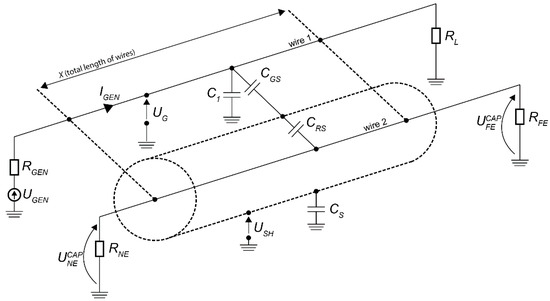
Figure 2.
Example of capacitive coupling between aggressor wire and shielded victim wire.
Shield not connected to the ground does not eliminate capacitive coupling at all. Since the capacitance CRS is larger than CGS, the equation for the interference voltage takes the same form as for a cable without shielding. If at least one end is connected to the ground, then the effect of capacitive coupling is completely eliminated (14).
In the case of inductive coupling (for the circuit as in Figure 3), the shielding effect mainly depends on the self-inductance LSH and resistance RSH of the shield, assuming double-sided grounding of the shield. It is necessary to ensure the highest possible current flow in the screen to compensate induced voltage in the receptor wire inside it.
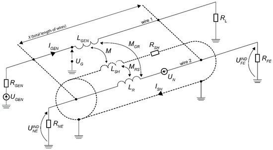
Figure 3.
Example of inductive coupling between aggressor wire and shielded victim wire.
If we assume, as in [15], that the mutual inductances MGR and M are equal to each other, and that MRS is equal to LSH, then the total noise voltage UN induced in the conductor 2 can be calculated on the basis of (15)
For higher frequencies, the formula (15) simplifies to (16)
The noise signal UN is divided at the ends of the receptor conductor in proportion to the values of terminations resistances RNE and RFE. For example, according to Figure 3, for the same RNE and RFE values, induced voltages at the line ends can be calculated according to (17)
4. Indirect Lightning Tests of Avionics Immunity
As a result of lightning discharges, electromagnetic disturbances can occur in aircraft systems, resulting in damage to avionics components or incorrect operation of these on-board systems, which in the worst case could be catastrophic. Therefore, it is required to conduct tests on the susceptibility of avionics systems to induced lightning transients. In the case of civil aircraft certification, one of the recommended standards is RTCA/DO-160, for which the lightning induced transient susceptibility test procedure is described in Section 22 [16]. There are three types of waveforms used during testing. They are single-stroke, multiple stroke and multiple burst pulses, the shapes of which are shown in Figure 4. They are intended to reflect indirect effects that may actually occur during lightning discharge to the aircraft.
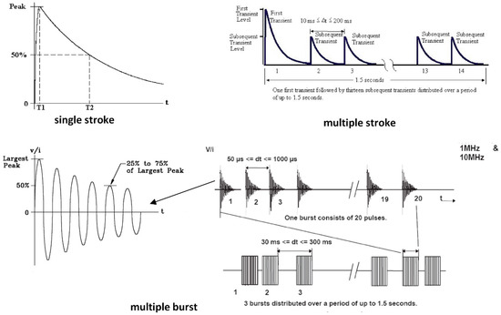
Figure 4.
Standardized waveforms recommended for indirect lightning tests of avionics immunity according to DO-160 standard [16].
Tests in accordance with the applicable requirements can be carried out in the Laboratory of Lightning Tests of avionics immunity operating at the Rzeszów University of Technology (RUT), Poland (Figure 5). A set of three modular impulse generators allows for the production of single strokes, multiple strokes, and multiple bursts with appropriate levels of peak values, and this set represents the main equipment of this laboratory, as well as meets the requirements of the standard with reserve. Computer simulations and experimental research conducted there enrich knowledge about the effects of lightning on electrical and electronic circuits [9,17]. The apparatus is also useful for other research in the area of lightning phenomena and their effects [18,19,20].
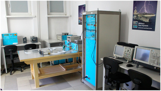
Figure 5.
General view of the test stand dedicated to indirect lightning tests of avionics immunity.
5. Experimental Setup
All experimental tests described in this paper were conducted on the stand which is shown in Figure 6.
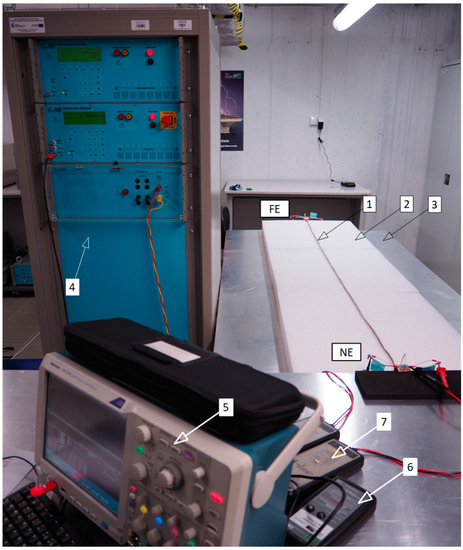
Figure 6.
The experimental setup for testing of indirect lightning effects: FE—far-end side, NE—near-end side, 1—cable bundle, 2—dielectric pad, 3—ground plane, 4—MS generator, 5—oscilloscope, 6—current probe, 7—voltage probe.
The setup included the tested wiring harness (1), which was described in detail in [9] and placed on an insulating pad (2) above the grounded metal plate (3); the multiple stroke MIG0600MS (EMC PARTNER AG, Laufen, Switzerland) generator (4); the DPO5204 (Tektronix, Inc., Beaverton, OR, USA) oscilloscope (5) with Rogowski current probe (6) and high voltage differential probes (7). A simplified electrical diagram of this configuration is shown in Figure 7.
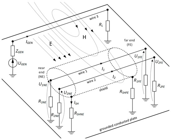
Figure 7.
The simplified electrical diagram of the tested system.
The cable bundle consisted of three LYc-L copper tinned wires, insulated with heat resistant PVC, marked in Figure 7 as “wire 1”, “wire 2” and “wire 3”. Wires “1” and “2”—with a core cross-section area of 0.35 mm2 and insulation thickness of 0.6 mm—were considered as signal wires. They were surrounded by tinned copper braided shield with a cross-sectional area of 3.4 mm2 (24 fibers with a diameter of 0.15 mm, 8 in the group and an angle of 15°). The third conductor “3”, with a cross-sectional area of 1.5 mm2 and 0.7 mm insulation thickness, was situated next to them.
In the studied model, wire 3 was treated as the power cord, in which surge current flowed as a result of multiple stroke lightning. An aluminum sheet, 1 m wide and 2 m long, was placed under a two-meter section of the prepared cable line and connected to the PE grounding terminal in the laboratory room. The opposite ends of the cable harness were called NE (near-end) and FE (far-end). The impulse current forced in wire 3 consisted of the first stroke and 19 subsequent strokes, which were spaced equally by time interval of 25 ms. Data regarding the shape and level of the injected current pulses resulting from the selected generator settings, the impedance of wire 3 and conditions of the tested system were collected. In this case, the rise time for each pulse of the current surge was about 20 μs. Peak value was about 1.1 kA for the first stroke and about 0.6 kA for subsequent ones. All of the signal wire ends were terminated to the ground (metal plate) by the same resistors, with resistance about 69 Ω as in [9]. Two configurations of braided shield termination were considered. For case “A”, the shield was grounded only at near-end. For configuration “B”, both ends were connected to the GND. Figure 8 shows injected current waveform achieved for case A.
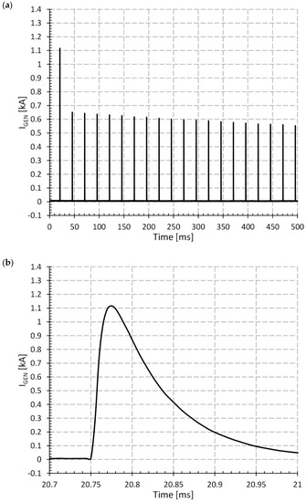
Figure 8.
The current waveform injected to the system for case A: (a) full time scale; (b) enlarged time scale.
6. Simulation Model of MTL
The model of the multi-conductor transmission line (MTL) based on [9] was used (see Figure 9). Computer simulations were conducted in CST Studio Suite 2019 [21]. Using the 3D editor, the nearest environment in which the wiring harness is located was defined, including electrical parameters and geometrical dimensions. Next, the cables, route of their laying, their structure and construction of surrounding screen were defined. Appropriate names were assigned to the ends of the wires. After selecting conductors and maximum distance between the wires to be taken into account, the whole bundle was divided into a finite number of simple segments. The program took into account the influence of metal objects in the vicinity of the ducts, finally defining the cross-section of each segment. The unit parameters of the transmission line (R’, L’, C’, G’) were calculated using a static 2D module. Finally, a sectional model of the line was created. Then, this model was imported into a built-in circuit simulator operating in the time and frequency domain. In the simulator, it was also possible to export the obtained model to an external program belonging to the SPICE family.
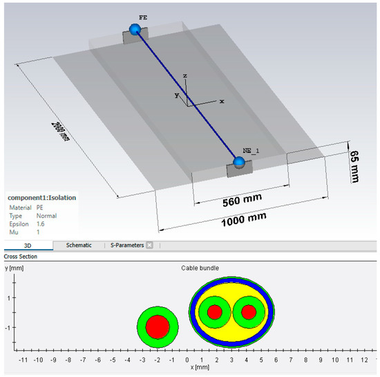
Figure 9.
The view of 3D model and cross section of the cable bundle.
The ready circuit diagram is shown in Figure 10. The wiring harness and its surroundings in the form of a grounded metal plate were represented by automatically creating a block with eight terminals, whose names correspond to previously defined designations of conductors and their terminals, which were assigned to the ends of a line loaded in 3D. During the simulation, the effect of considering parasitic capacitance and inductance of the resistor at the ends of the line on the obtained results of calculations was examined. The parameters of the resistors correspond to those in the experimental model, which were measured with the LCR bridge.
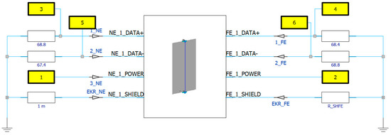
Figure 10.
The circuit diagram of the tested system.
To introduce the disturbance in the form of a current surge, the possibility of an external port, indicated in Figure 10 (in the form of a yellow rectangle with the number 1), was used. It is possible to model external sources or loads with the use of this type of block, indicating the character of changes in its voltage or current and impedance. It was connected to the terminal of wire 3 on the NE side named as NE_1_POWER. The second hidden branch of port 1 was connected to the conventional reference ground. The probes (triangle symbol) were placed at the appropriate points to display the selected voltage and current signals.
In order to refer to the experimental results, work was focused on performing calculations at the same surge current of wire 3. The waveform of the injected impulse was loaded in the form of an ASCII text file, achieved from the oscilloscope during experiments and separate for the both A and B configurations.
7. Results and Discussion
Voltage transients induced in wires 1 and 2 were measured and calculated at the ends of each of them. In general, transients resulted from capacitive and inductive coupling between the wires. The observed voltages are of the common mode type, and therefore, similarities between the waveforms in wires 1 and 2 were expected. Due to some asymmetry in the arrangement of these conductors inside the bundle and differences in parameters of these lines, the observed voltages (see Figure 11) were slightly different from each other. A similar situation was observed in [9].
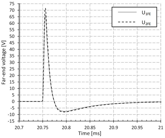
Figure 11.
The comparison of measured voltages of wire 1 and 2 at far-end for case A.
In Figure 12 and Figure 13, a comparison of experimental and simulation results was made for a selected point in the circuit for condition A. There was the voltage of wire 1 at far-end, while the shielding braid was grounded at only one end. The nature of the changes in both the measured and calculated waveforms is similar. The first stroke was observed with a higher peak value and 19 subsequent ones with a maximum value that was lower by about half. No significant reflections were detected.
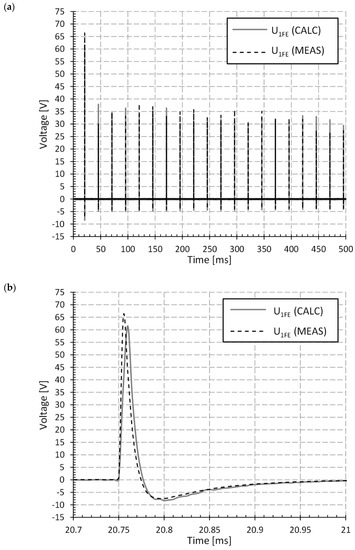
Figure 12.
The comparison of measured and calculated voltage of wire 1 at far-end: (a) full time scale, (b) view of the first stroke.
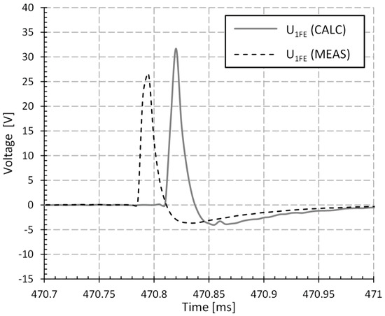
Figure 13.
The comparison of measured and calculated voltage of wire 1 at far-end—the view of 18th subsequent stroke.
Some discrepancies were noted mainly due to inaccuracy in the model and simulation settings. This was especially evident when observing individual strokes. The last ones differed most in the moment of appearance and the peak value (see Figure 13). The obtained time differences between measured and calculated waveforms may be caused by both propagation effects and the adopted parameters of numerical simulations. Such discrepancies do not appear during the simulation of indirect lightning effects in the form of single pulse.
A summary of the measurement and calculations of voltage at the near-end of the line 2 for the case B (two-sided shield grounding) is shown in Figure 14. A significant, almost 6-fold reduction in the peak of induced voltage was noted, as compared to case A. In [8], it was found that the use of wire shielding reduces the induced overvoltages in the on-board installation of an aircraft on a similar level, as was presented in this work. Computer simulations for the proposed model led to the observation of overvoltages in signal lines with peak values higher than those measured. For determining the minimum required level of devices’ immunity, there could only be an overestimation.
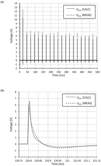
Figure 14.
The comparison of measured and calculated voltage of wire 2 at far-end: (a) full scale view; (b) view of the 8th subsequent stroke.
Using the prepared model, the parameters of the scattering matrix (S-parameters) describing signals propagated in the tested multi-conductor transmission line were also calculated (see Figure 15). For this purpose, ports have been assigned to each end of the line as in Figure 10.
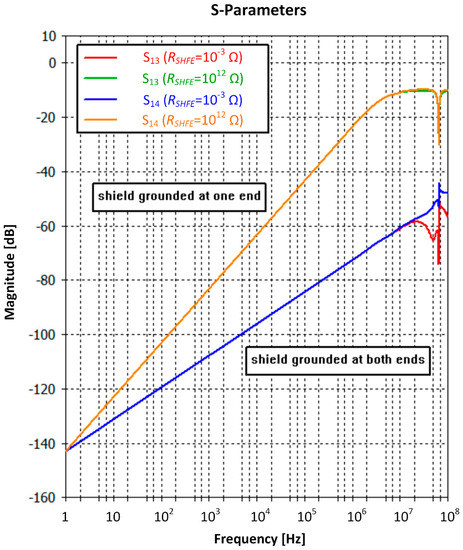
Figure 15.
The comparison of S-parameters for shield grounding cases A (one side termination to GND) and B (both side termination to GND).
Each of the matrix parameters has its own physical interpretation. S-parameter analysis can provide information about attenuation, reflections and line crosstalk [21,22]. The influence of shield grounding resistance RSHFE at far-end on S13 and S14 S-parameters, for shield grounding at near side by low resistance, was shown in Figure 15. Observations of S13 and S14 in frequency domain allowed for the determination of approximately near and far crosstalk between conductor 3 (aggressor) and conductor 1 (victim). In this case, the use of properly grounded cable screen means up to 50 dB lower levels of induced voltages than in the case of one side grounding.
8. Conclusions
Experimental and computer studies of the propagation of lightning surges in a model of an aircraft wiring harness were carried out. The effect of shield screen grounding on the suppression of induced overvoltages along the lines surrounded by the braided shield has been investigated. A multiple stroke surge with a peak over 1 kA for the first pulse, representing indirect lightning effects, was injected into the system during experimental tests. The induced overvoltages corresponded to the characteristics of current changes. For both measurement and calculations, a clear 5-fold suppression was observed after grounding the screen from both sides, in comparison to the one-sided connection of the braided screen to the ground. The influence of a bilaterally grounded cable screen was also demonstrated by computed S-parameters. The frequency response of the scattered matrix shows that crosstalk between aggressor and victim line will be more noticeable for higher frequency signal components, but they will also be more suppressed by using the screen, as expected.
When comparing the measurements with the simulations for the same point of the system, good compliance was noticed with some small discrepancies. Therefore, the presented model can be used to estimate indirect lightning effects in the wiring harness of avionics. The obtained time differences between measured and calculated waveforms of the last pulses belonging to the multi-stroke waveform may be caused by both propagation effects and the adopted parameters of numerical simulations. Such discrepancies do not appear during simulation of indirect lightning effects in the form of a single pulse. Further work is planned to continue to improve our measurement setup and the numerical model of complex avionics systems during the multi-stroke lightning interaction, leading to better correspondence to real atmospheric phenomena during a thunderstorm.
Author Contributions
Conceptualization, G.M.; methodology, K.F.; software, K.F.; validation, K.F. and G.M.; formal analysis, K.F.; investigation, K.F.; resources, K.F. and S.H.; data curation, K.F.; writing—original draft preparation, K.F. and S.H.; writing—review and editing, K.F. and G.M.; visualization, S.H.; supervision, G.M.; project administration, G.M.; funding acquisition, G.M. All authors have read and agreed to the published version of the manuscript.
Funding
This research and the APC were funded by Minister of Science and Higher Education of the Republic of Poland: Maintain the research potential of the discipline of automation, electronics and electrical engineering. Grant number: PB22.ET.21.001.
Conflicts of Interest
The authors declare no conflict of interest.
References
- Parmantier, J.P.; Issac, F.; Gobin, V. Lightning Hazards to Aircraft and Launchers: Indirect Effects of Lightning on Aircraft and Rotorcraft. Aerosp. J. 2012, 5, 1–27. [Google Scholar]
- Morgan, D.; Hardwick, C.J.; Haigh, A.J.; Meakins (Cobham), A.J. Lightning Hazards to Aircraft and Launchers: The Interaction of Lightning with Aircraft and the Challenges of Lightning Testing. Aerosp. J. 2012, 5, 1–10. [Google Scholar]
- Uman, M.A.; Rakov, V.A. The interaction of lightning with airborne vehicles. Prog. Aerosp. Sci. 2003, 39, 61–81. [Google Scholar] [CrossRef]
- Laroche, P.; Blanchet, P.; Delannoy, A.; Issac, F. Lightning Hazards to Aircraft and Launchers: Experimental Studies of Lightning Strikes to Aircraft. Aerosp. J. 2012, 5, 4–13. [Google Scholar]
- Boissin, J.-F.; Flourens, F.; de Boer, A.; Bardet, M.; Herve, A.; Perez, G.; Riccio, L. In-flight lightning measurements and reconstruction on a metallic and composite aircraft. In Proceedings of the 2012 ESA Workshop on Aerospace EMC, Venice, Italy, 21–23 May 2012; pp. 1–6. [Google Scholar]
- Sun, C.; Zhang, M. Simulation design of harness protection against lightning for aircrafts. In Proceedings of the 2014 International Conference on Lightning Protection (ICLP), Shanghai, China, 11–18 October 2014; pp. 1254–1257. [Google Scholar]
- McCreary, C.A.; Lail, B.A. Lightning transient suppression circuit design for avionics equipment. In Proceedings of the IEEE International Symposium on Electromagnetic Compatibility, Pittsburgh, PA, USA, 6–10 August 2012; pp. 93–98. [Google Scholar]
- Zhang, M.; Huang, Z. Transient Current Burst Analysis induced in Cable Harness due to Direct Lightning Strike on Aircraft. In Proceedings of the 2010 Asia-Pacific International Symposium on Electromagnetic Compatibility, Beijing, China, 12–16 April 2010; pp. 1197–1200. [Google Scholar]
- Filik, K.; Masłowski, G. Analysis of Lightning Induced Transients in an Aircraft Cable Bundle Model. Sci. Lett. Rzesz. Univ. Technol. J. Electr. Eng. 2018, 26, 5–24. [Google Scholar]
- Paul, C.R. Introduction to Electromagnetic Compatibility, 2nd ed.; Wiley Interscience: Hoboken, NJ, USA, 2006. [Google Scholar]
- Solak, V.; Efendioglu, H.S.; Colak, B.; Garip, M. Analysis and Simulation of Cable Crosstalk. In Proceedings of the 2017 IV International Electromagnetic Compatibility Conference (EMC Turkiye), Ankara, Turkyie, 24–27 September 2017. [Google Scholar]
- Freire, R.C.C.; de Souza Mariano, J.A. Surface Transfer Impedance Characterization of Shielded Cables. In Proceedings of the 2019 International Symposium on Lightning Protection (XV SIPDA), Sao Paulo, Brazil, 30 September–4 October 2019; pp. 1–6. [Google Scholar]
- Xu, M.; Wang, Y.; Li, X.; Dong, X.; Zhang, H.; Zhao, H.; Shi, X. Analysis of the Influence of the Structural Parameters of Aircraft Braided-Shield Cable on Shielding Effectiveness. IEEE Trans. Electromagn. Compat. 2020, 62, 1028–1036. [Google Scholar] [CrossRef]
- Mora, N.; Rachidi, F.; Pelissou, P.; Junge, A. Cable crosstalk analysis and simulation: A comparison between low frequency circuit approach and transmission line theory. In Proceedings of the ESA Workshop on Aerospace EMC, Venice, Italy, 21–23 May 2012; pp. 1–6. [Google Scholar]
- Ott, H.W. Electromagnetic Compatibility Engineering; J. Wiley & Sons Inc.: Hoboken, NJ, USA, 2009. [Google Scholar]
- RTCA/DO-160G, Environmental Condition and Test Procedures for Airborne Equipment Section 22: Lightning Induced Transient Susceptibility; RTCA, Incorporated: Washington, DC, USA, 2010.
- Filik, K.; Masłowski, G. Analysis of lightning transients induced in NAV/COMM system of aircraft. Przegląd Elektrotechniczny 2016, 92, 263–267. [Google Scholar]
- Filik, K.; Karnas, G.; Szczupak, P.; Maslowski, G.; Ziemba, R. Experimental investigation of the effectiveness of lightning protection system. In Proceedings of the 2016 13th Selected Issues of Electrical Engineering and Electronics (WZEE), Rzeszow, Poland, 4–8 May 2016; pp. 1–6. [Google Scholar]
- Wyderka, S.; Maslowski, G.; Ziemba, R.; Karnas, G. Frequency characteristics of supplying transformer and electrical appliances of residential building in modeling of lightning current distribution. In Proceedings of the 2012 International Conference on Lightning Protection (ICLP), Vienna, Austria, 2–7 September 2012; pp. 1–5. [Google Scholar]
- Karnas, G.; Filik, K.; Szczupak, P.; Masłowski, G. Calibration of electric field antennae operating in the ELF-MF frequency range at the lightning research station in Rzeszow. In Proceedings of the 2016 13th Selected Issues of Electrical Engineering and Electronics (WZEE), Rzeszow, Poland, 4–8 May 2016; pp. 1–6. [Google Scholar]
- CST-Computer Simulation Technology GmbH, CST Studio Suite. 2019. Available online: www.cst.com (accessed on 1 September 2018).
- Kurokawa, K. Power Waves and the Scattering. IEEE Trans. Microw. Theory Techn. 1965, 13, 194–202. [Google Scholar] [CrossRef]
Publisher’s Note: MDPI stays neutral with regard to jurisdictional claims in published maps and institutional affiliations. |
© 2021 by the authors. Licensee MDPI, Basel, Switzerland. This article is an open access article distributed under the terms and conditions of the Creative Commons Attribution (CC BY) license (https://creativecommons.org/licenses/by/4.0/).