Article

Experimental Investigation of Combustion Characteristics on Opposed Piston Two-Stroke Gasoline Direct Injection Engine

1
School of Energy and Power Engineering, North University of China, University Road No.3, Taiyuan 030051, China
2
China North Engine Research Institute, Yong Jin Road No.96, Tianjin 300400, China
3
School of Mechanical and Vehicle Engineering, Beijing Institute of Technology, Zhongguancun South Street No.5, Beijing 100081, China
*
Author to whom correspondence should be addressed.
Energies 2021, 14(8), 2105; https://doi.org/10.3390/en14082105
Submission received: 4 March 2021 / Revised: 5 April 2021 / Accepted: 5 April 2021 / Published: 9 April 2021

Abstract

:
The combustion characteristics of an opposed-piston two-stroke gasoline engine are investigated with experiment. The energy conversion and exergy destruction are analyzed and the organization method of the combustion process is summarized. The effects of phase difference, scavenging pressure, injection timing, ignition timing, and dual spark plug ignition scheme on the combustion process and engine performance are discussed, respectively. The heat release rate of the opposed-piston two-stroke gasoline engine is consistent with the conventional gasoline engine. With the increase of opposed-piston motion phase difference, the scavenging efficiency decreases and overmuch residual exhaust gas is not beneficial to the combustion process. Meanwhile, the faster relative velocity of the opposed-piston near the inner dead center enhances the cylinder working volume change rate, which leads to the rapid decline of in-cylinder pressure and temperature. The 15 °CA of opposed-piston motion phase difference improves the scavenging and combustion process effectively. When scavenging pressure is 0.12 MPa, the scavenging efficiency and heat release rate are improved at medium-high speed conditions. With the delay of injection timing, the flame developing period decreases gradually, and the rapid burning period decreases and then increases. The rapid burning period may reach the minimum value when the injection advance angle is 100 °CA. With the delay of ignition timing, the flame developing period increases gradually, and the rapid combustion period decreases and then increases. The rapid combustion period may reach the minimum value when the ignition advance angle is 20 °CA. Notably, the flat-top piston structure should be matched with the dual spark plug, which the ignition advance angle is 20 °CA at medium-high load conditions.

1. Introduction

Facing the energy and environmental crisis, traditional fuel engines have gradually realized a variety of combustion methods such as the premixed charge compression ignition (PCCI), low-temperature combustion (LTC), homogeneous charge compression ignition (HCCI), high-pressure common rail (CR) technology, gasoline direct injection (GDI) technology, variable valve time (TTV) technology, exhaust gas recirculation (EGR) technology, and special combustion chamber structures [1]. Today’s technology leveraging allows the opposed-piston two-stroke (OP2S) engine to be considered as an alternative for the conventional four-stroke engines as a mechanical drive in various applications. With the application of modern design technology, the OP2S-GDI engine has been reemphasized [2,3]. OP2S-GDI engine is a kind of reciprocating engine with different structures from traditional engines [4,5]. OP2S-GDI engine is one of the OP2S engines and the synchronous movements of the opposed-pistons are guaranteed by opposed crank-link mechanism. As cylinder heads are removed from the combustion system, fuel injectors and spark plug are installed on the cylinder liner [6]. In general, OP2S-GDI engines are suited to compete with conventional four-stroke engines whose power-to-bulk volume ratio, power-to-weight ratio, and fuel efficiency are requirements [7].
In recent years, research has been extensive for the OP2S engine working process. For the combustion process of the OP2S engine, Enrico et al. optimized the combustion process of the OP2S engine, so that the indicated power at full load increased by 15% [8]. The peak in-cylinder pressure and turbine inlet temperature were reduced to some extent, and the NOx emission could be reduced by changing the injection strategy. Bo et al. established a three-dimensional CFD computational model of the gas motion and spray characteristics of a high-speed direct injection diesel engine, and analyzed the effects of different forms and characteristics of the gas motion on the spray shape and mixture concentration [9]. According to the idling condition of the engine, Frank et al. carried out the simulation calculation of the dual opposed two-stroke engine under the idling condition and analyzed the experiment and simulation, which optimized the scavenging and combustion process of the engine by adjusting the intake and combustion parameters [10]. Huo et al. studied the influence of the new combustion chamber shape on the dual opposed two-stroke engine [11]. By using the annular combustion chamber shape, the gas flow and heat transfer effect can be improved, and the combustion process can be more stable. Bebe et al. compared the experimental data and CFD simulation data of a single nozzle [12]. The experimental results of a single nozzle are relatively consistent with the results of CFD simulation analysis, but the error between them is large in the early stage of injection. Turner et al. analyzed and optimized the scavenging volume and indicated the fuel consumption rate of a direct-injection two-stroke gasoline engine, and the results showed that the opposed-piston configuration could achieve maximum expansion and minimum heat transfer, so the fuel consumption was reduced by 9.6% compared with a normal return scavenging engine [13]. Khanh et al. studied the effect of different nozzle diameters on spray and combustion, and the spray length decreased with decreasing nozzle diameter and increasing injection pressure [14]. The ignition delay period and nozzle diameter showed a non-linear relationship. Redon et al. experimentally tested a 4.9 L three-cylinder OP2S engine on an engine dynamometer with an effective thermal efficiency of up to 43% and some control of NOx and carbon emissions by reducing the hysteresis of torque rise during load rise [15]. Hassantabar et al. investigated the effect of engine speed and flight altitude on the performance of the throttle injection system of a two-stroke engine, whose scavenging process was analyzed by the engine simulation software LES [16]. As the engine speed increases, the intensity of turbulence in the cylinder increases, and subsequently the effect on the spray gradually increases. Yang et al. investigated the air exchange process of OP2S diesel engines by building a three-dimensional model of the diesel engine and analyzing the effect of intake and exhaust port height on the intake process [17]. The effect of increasing the height of the intake and exhaust ports on the intake process was analyzed. The air exchange effect is better when the ratio of intake and exhaust port height to engine stroke is 0.11~0.15. Ma et al. divided the combustion process of an opposed-piston two-stroke engine into four periods: ignition delay, premixed combustion, diffusion combustion, and afterburning, and increasing the diffusion combustion period increased the indicated mean effective pressure [18]. Increasing the diffusive combustion period increases the indicated mean effective pressure from 0.351 MPa to 0.703 MPa and reduces the in-cylinder pressure rise rate by 7%. At the same time, the opposed-piston motion phase difference, gas change timing, injection and ignition timing were investigated [6]. Zhang et al. investigated the combustion and emission performance of a double opposed-piston engine [19]. Multiple injections are effective in reducing carbon soot emissions, which in turn increases NOx emissions. Liu et al. also carried out a simulation study for different intake and exhaust pressure differentials [20]. The simulation results show that an increase in pressure difference is beneficial to the indicated efficiency of the engine, while the trapping efficiency decreases.
The above literature shows that there are many research directions on the performance simulation of OP2S engines, and there is a lot of research space. A large part of the simulation research on OP2S engine focuses on the ventilation stage of the engine, and more on the ventilation parameters such as intake and exhaust ports and pressure difference. Therefore, it is necessary to increase the research on the combustion process of OP2S engines. Although many people have analyzed the in-cylinder combustion process of fuel, most of them focus on the four-stroke internal combustion engine, and there are not many types of research on OP2S engines. Many pieces of research are carried out by the simulation model of the whole engine performance which cannot directly reflect the fuel injection combustion process of the engine. There is not much research on the combustion process of the OP2S engine.
For the internal combustion engine test, indicated mean effective pressure (IMEP) is used to calculate the rate of heat release (ROHR) and analyze the combustion characteristics [21]. The heat release (HR) analysis is based on ROHR calculation from the cylinder gas pressure (CGP) versus crank angle (CA) data. At the same time, Rakopoulos and Giakoumis presented a comprehensive review of works related to second-law analysis for reciprocating internal combustion engine operation applications [22]. By the energy and exergy analyses, the conversion of energy by combustion process and destruction of exergy by irreversible processes are used to evaluate engine performance, which is related to power loss of engine directed [23]. Bahar Sayin Kul et al. [24] presented an energy and exergy analysis for a single-cylinder, water-cooled diesel engine using biodiesel, diesel, and bioethanol blends under transient load conditions from both a first and second law perspective. The fuel energy rate, exhaust energy rate, lost energy rate, brake power with first law analysis, fuel exergy rate, brake power exergy, exhaust exergy rate, the exergy rate through heat transfer, and exergy destruction rate with exergy analysis were calculated for each fuel using results of tests performed at different speeds. Javier Monsalve-Serrano et al. [25] applied a 1D simulation and experimental to study the effects of the injection parameters in methane–diesel dual-fuel combustion. The efficiency and emissions were compared to the conventional diesel combustion mode. Ramos da Costa et al. [26] investigated theoretically and experimentally the performance characteristics of a dual diesel engine using natural gas and diesel in terms of both energy and exergy analyses.
In this paper, a new-type OP2S-GDI engine is developed by the Beijing Institute of Technology. Compared with the combustion chamber of a traditional GDI engine, the OP2S-GDI engine not only increases the difficulty of the gas exchange process but also puts forward new requirements for the organization of the combustion process [6,10]. Therefore, it is necessary to match the scavenging pressure, opposed-piston motion, injection and ignition timing, and ignition system scheme, to realize the reasonable combustion characteristics in the cylinder. This study aims to analyze the OP2S-GDI engine combustion process and to evaluate the effect of a unique combustion system and opposed-piston relative movement rule on the performance and combustion characteristics of the OP2S-GDI engine by using the ROHR and CGP. Based on the experimental study on the combustion process of OP2S-GDI engine, the energy conversion and exergy destruction are analyzed, the effect factor of combustion characteristics is analyzed, and the organization method of the combustion process is summarized.

2. Principal Prototype Test Platform

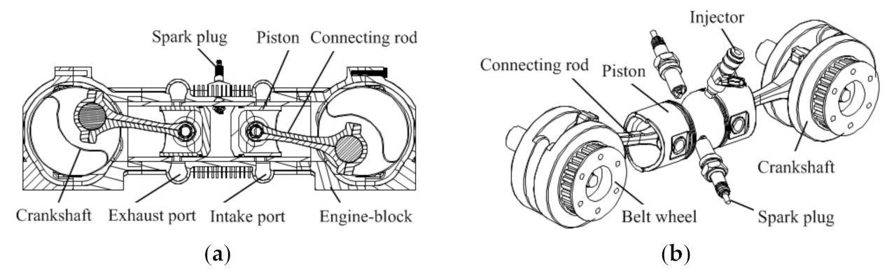
2.1. OP2S-GDI Engine Prototype

As shown in Figure 1, the OP2S-GDI engine is equipped with a uniflow scavenging system [6]. The OP2S-GDI is a type of piston engine. Due to the configuration of the opposed-piston, there is no cylinder head and valve distribution mechanism, which realizes the exchange process by the intake and exhaust ports of the cylinder liner. OP2S-GDI engine achieves separation of fuel injection and scavenging process and rapid combustion by adopting uniflow scavenging method, gasoline direct injection, and dual spark plug ignition. The structure parameters are shown in Table 1.

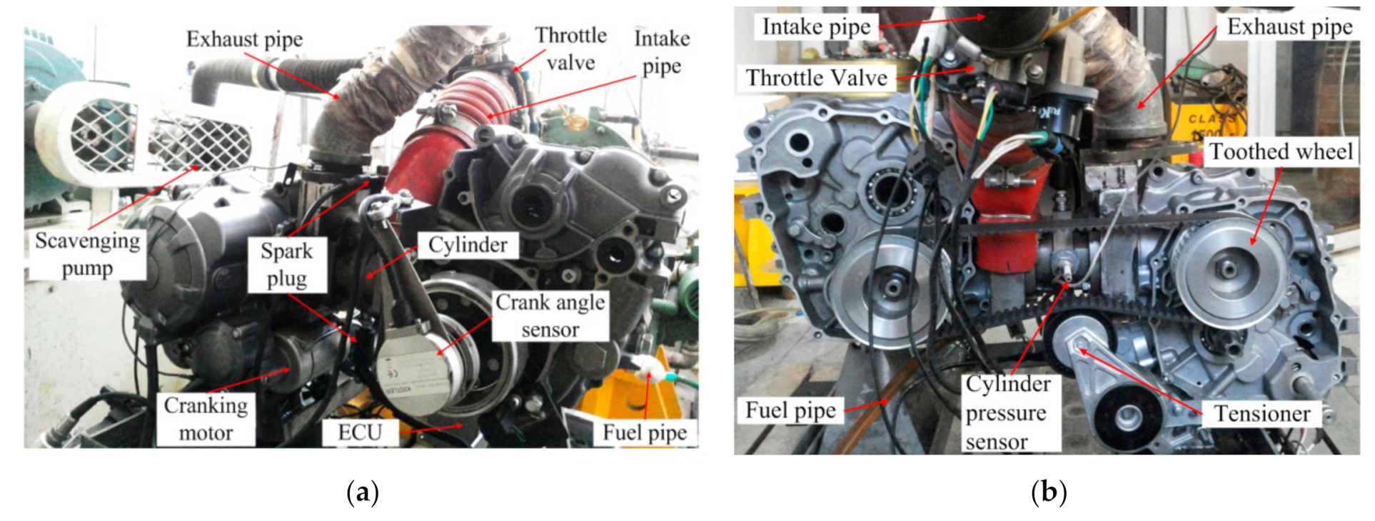
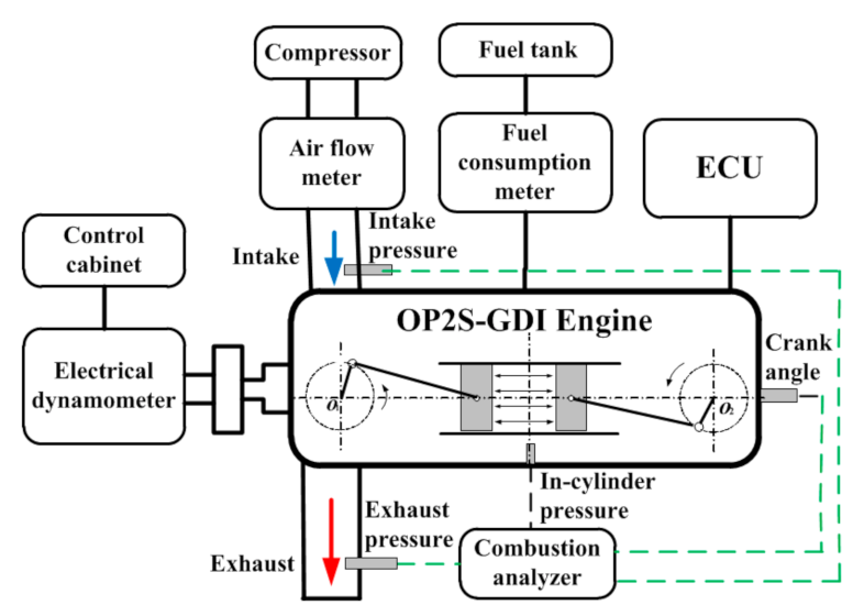
2.2. OP2S-GDI Engine Experimental Test Bed

As shown in Figure 2, the principal prototype of the OP2S-GDI engine is based on two small gasoline engines with 0.125 L single cylinder displacement. Based on the structural design of the cylinder liner and the synchronous design of the crank-connecting rod mechanism is carried out. The crankshaft on the intake and exhaust side of the OP2S-GDI engine has a shorter distance, and the mechanism is required to be as simple, reliable, and easy to install as possible. Therefore, the gear belt drive is chosen as the synchronous mechanism scheme, which not only ensures the synchronous movement of the opposite piston but also realizes the confluence of the output torque of the crankshaft on both sides. At the same time, the combustion system is designed by matching the scavenging system, fuel injection system, and ignition system.
The schematic of the engine test bench of the OP2S-GDI engine prototype is shown in Figure 3. The model and parameters of the test instrument were shown in Table 2.

3. Analysis of OP2S-GDI Engine Performance

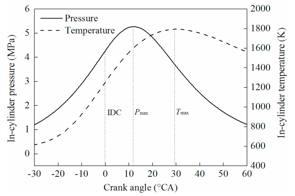
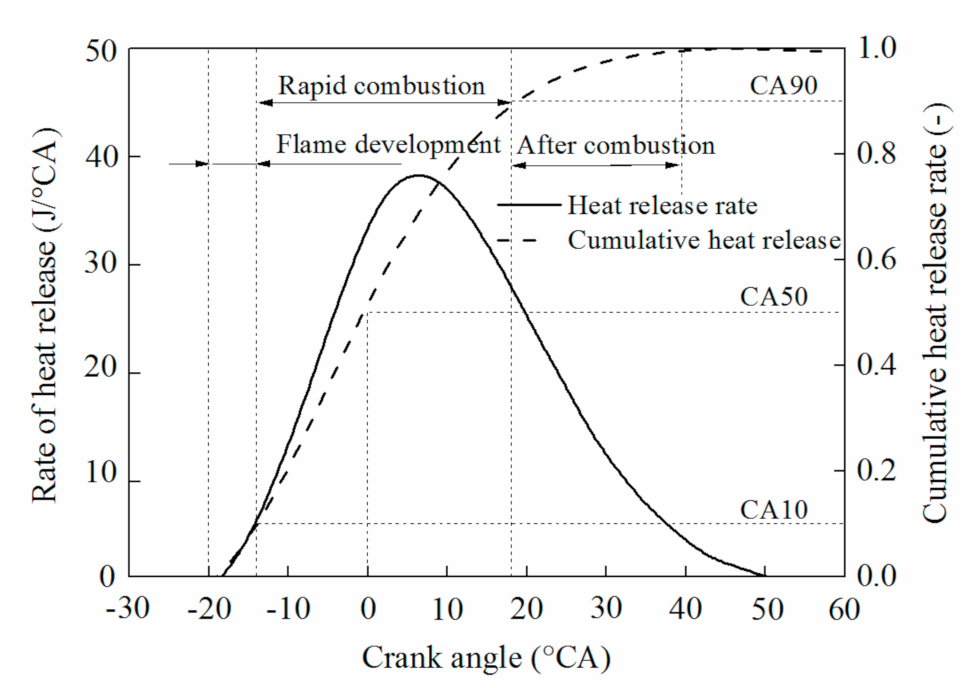
3.1. Analysis of Combustion Process Organization

Heat release (HR) calculations are an approach to acquire information about combustion processes. HR analysis is performed based on cylinder gas pressure (CGP) data [21,22]. The most widely used one was developed by Krieger and Borman [27].
The cylinder gas pressure (CGP) data is tested by the OP2S-GDI engine experimental system. To acquire information on combustion processes, the heat release (HR) is calculated by CGP. Reference [27] describes the calculation process of HR for the traditional gasoline engine. From the first law of thermodynamics:
d U d t = d Q d t d W d t
m C v d T d t = d Q d t P d V d t
where d Q / d t is the combination of the heat release rate and heat transfer rate across the cylinder wall, d W / d t is the rate of work done by the system due to system boundary displacement.
To simplify Equation (2) the ideal gas assumption can be used:
P V = m R T
Assuming constant mass, Equation (3) is differentiated as
d T d t = 1 m R [ P d V d t + V d P d t ]
After combining these two equations, the heat release equation becomes
d Q d t = [ C v R + 1 ] P d V d t + C v R V d P d t
After replacing time (t) with the crank angle ( θ ); Equation (5) becomes
d Q d θ = λ λ 1 P d V d θ + λ λ 1 V d P d θ
where λ is the ratio of specific heats, and C v / R = 1 / ( λ 1 ) ; θ is crank angle; P is cylinder gas pressure; V is cylinder volume [28].
Based on the CGP data, energy conservation equation, and empirical heat transfer formula, the heat release process of fuel combustion is calculated to analyze the combustion of internal combustion engines, including in-cylinder temperature, instantaneous heat release rate, and cumulative heat release rate. Figure 4 and Figure 5 are the experimental results of combustion pressure, temperature, heat release rate, and cumulative heat release rate of OP2S-GDI engine at rotating speed of 3000 rpm and scavenging pressure of 0.12 MPa. The maximum combustion pressure of OP2S-GDI engine is 5.3 MPa, the corresponding equivalent crankshaft angle is 12.6 °CA, the maximum combustion temperature is 1795 K, and the corresponding equivalent crankshaft angle is 29.2 °CA. The heat release rate curve is similar to that of a traditional gasoline engine [6].
To meet the need of combustion system research, this paper divides the combustion process into three stages by using the method of average combustion speed analysis in stages: (1) flame development stage, from the beginning of cumulative heat release to 10% of the cumulative heat release (CA10) which starts from the begin of combustion to rapid combustion; (2) rapid combustion stage, from CA10 to 90% of the cumulative heat release (CA90), is the main combustion stage. The combustion phase and combustion speed can affect the thermodynamic performance of the engine; (3) in the later combustion stage, less work is done, the uncontrollability of the combustion process is greater, and less attention is paid in engineering. As shown in Figure 5, the in-cylinder combustion process of the OP2S-GDI prototype engine is analyzed according to the exothermic process of the traditional gasoline engine. The combustion center of gravity (50% of the cumulative heat release, CA50) is located at the dead center of the opposed piston motion. The flame development period is 6.4 °CA, and the fast combustion period is 32.5 °CA.

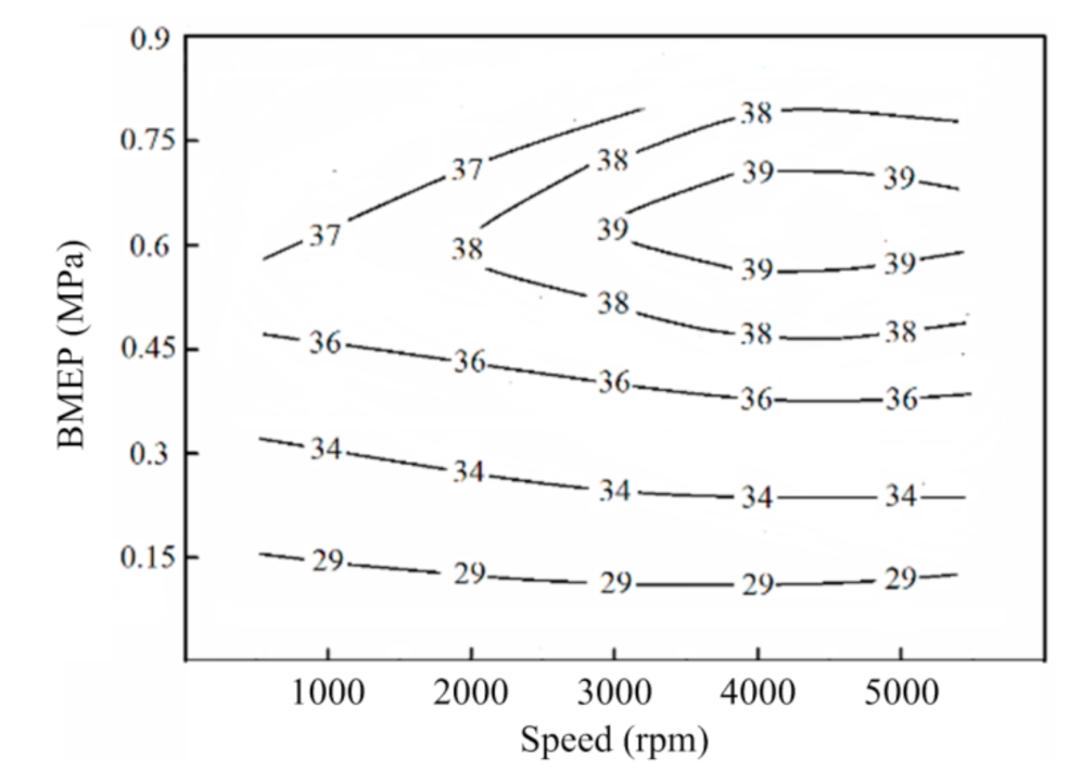
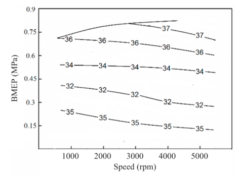
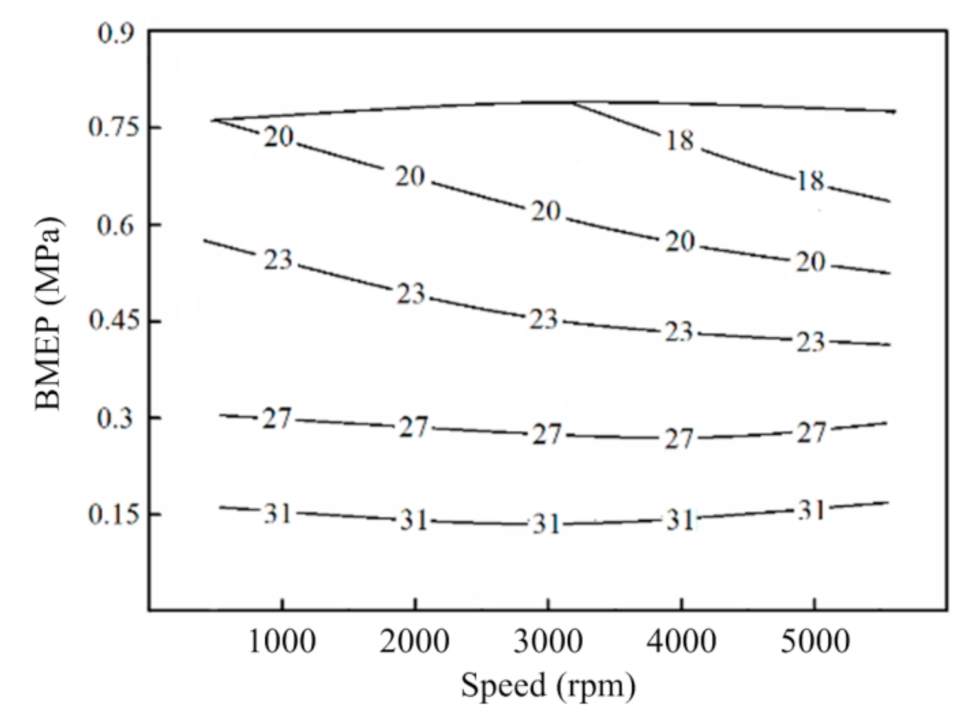
3.2. Analysis of Energy and Exergy

The heat flow into the internal combustion engine includes the chemical energy of the fuel and the enthalpy of the intake air, while the heat flow out of the internal combustion engine includes the effective power, the heat taken away by the exhaust, the heat taken away by the cooling medium, the unburned fuel and the heat lost by convection and radiation. The steady-state heat balance equation of an internal combustion engine is shown as follows:
H f u e l = P e + ( H e x H i n ) + Q c o o l i n g + Q m i s c
where, H f u e l is fuel chemical energy.
H f u e l = m ˙ f H L
where, m ˙ f is the fuel mass flow, HL is the fuel calorific value, Pe is the effective power, Hex is the exhaust enthalpy.
H e x = ( m ˙ a + m ˙ f ) c p e x T e x
where, m ˙ a is the intake mass flow rate, cp-ex is the specific heat capacity of the exhaust at constant pressure, Tex is the exhaust temperature, Hin is the exhaust enthalpy.
H i n = m ˙ a c p i n T i n
where, cp-in is the specific heat capacity of the intake at constant pressure, Tin is the intake temperature, Qcooling is the heat transferred to the cooling medium.
Q c o o l i n g = m ˙ w c w ( T e x w T i n w )
where, m ˙ w is the mass flow rate of cooling water, cw is the specific heat capacity of cooling water, Tin-w and Tex-w is inlet and outlet temperature of cooling water, Qmisc is other losses.
To analyze the energy distribution of internal combustion engines more intuitively, each energy is converted into a percentage of the total heat of fuel.
η f = η e t + η e x + η c o o l i n g + η m i s c = 100 %
η et = P e H f u e l 100 %
η ex = H e x H i n H f u e l
η c o o l i n g = Q c o o l i n g H f u e l
η misc = Q 3 H f u e l
where, η f is the ratio of chemical energy to the fuel, η e t is the effective thermal efficiency, η e x is the ratio of exhaust energy to total heat, η c o o l i n g is the ratio of heat transferred to the cooling medium to the total heat, η m i s c is the ratio of other losses to total heat.
Figure 6 shows the distribution of the effective thermal efficiency of the diesel engine. Under low load conditions, the effect of load on the effective thermal efficiency is greater than that of speed, while under high load conditions, the effect of speed on the effective thermal efficiency is greater. Under the same speed, the effective thermal efficiency increases first and then decreases with the increase of load, because at low load, the power output is less and the proportion of friction work is large, while the thermal efficiency is indicated to change less when the speed and other factors remain unchanged, with the increase of load, the friction work basically remains the same, the output work increases and the effective thermal efficiency increases. While at high loads, the excess air coefficient decreases leading to the deterioration of combustion, the indicated thermal efficiency decreases, the friction work remains unchanged and the effective thermal efficiency decreases accordingly. Two-stroke engines are strongly influenced by the quality of air exchange, so the effect of speed on effective thermal efficiency increases at high loads. The peak region of the effective thermal efficiency of an OP2S-GDI engine is at mid-load near 3000 r/min and above, and the speed is higher compared to a conventional engine because the maximum burst pressure is smaller and the frictional losses are reduced for the same operating conditions.
Figure 7 shows the distribution of the exhaust term heat as a percentage of fuel energy, from which it can be found that the exhaust term heat is higher at most operating conditions, with about one-third of the fuel energy being carried away by the exhaust gas and the smallest percentage of exhaust energy at low and medium loads. At the same load, as the speed increases, the proportion of exhaust heat increases. This is because as the speed increases, the heat transfer time per cycle decreases, and more energy flow out with the exhaust.
Figure 8 shows the distribution of the heat transferred to the cooling term as a proportion of the fuel energy. As can be seen from the graph, the proportion of the heat to the cooling term is larger in the low load region, where the speed has a small effect and only decreases with increasing load. This is because at low loads the proportion of mechanical losses is greater and most of these are eventually transferred to the cooling water through thermal conversion. As the load increases, the influence of the rotational speed on the cooling term increases, and at medium and high loads the proportion of heat transferred to the cooling term decreases as the rotational speed increases.
The previous section used the first law of thermodynamics to analyze the heat balance of an opposed-piston two-stroke diesel engine, which is based on the law of conservation of energy and clarifies the quantitative relationship between energy in the thermal process. Through the analysis, it is found that the sum of heat loss and exhaust energy loss is greater than 50% under most operating conditions of the diesel engine, and the heat loss changes from heat loss as the main part to exhaust energy as the operating conditions change from low speed and small load to high speed and large load. To further explore the efficient use of energy, it is not enough to analyze the energy relationship, but also the “quality” of the energy, i.e., the effective energy analysis in conjunction with the second law.
In contrast to mechanical energy, waste heat is a lower quality of energy and cannot be fully converted into usable energy, so it needs to be further converted into effective work through the thermal cycle. The Carnot cycle embodies the highest efficiency of work done by the work mass. The thermal cycle calculation of waste heat using the Carnot cycle allows the analysis of the potential maximum available energy of waste heat. The equation for the Carnot cycle is as follows.
E X , Q = Q ( 1 T 0 T )
where, EX,Q is the available energy of the waste heat, Q indicates the energy of the waste heat, T0 indicates the ambient temperature and T indicates the temperature of the waste heat.
η E xe , p = ( 1 T 0 T ) 100 %
where, ηExe,p indicates the available energy from waste heat as a proportion of the energy from waste heat.
η E x e , e f f = E Q , e x H f u e l
The ηExe,eff indicates the percentage of waste heat available as a percentage of the total fuel energy.
Figure 9 shows the proportion of each energy available to itself when the load is 0.8 MPa. Because the cooling medium has a large flow rate and a large specific heat capacity, it is less affected by the operating conditions and the temperature difference between the import and export of the cooling medium is small. Moreover, to ensure that the diesel engine is in a suitable operating condition, the cooling medium should be guaranteed at a suitable temperature and should not be utilized. Opposed-piston two-stroke diesel engine by the restrictions of the gas exchange mode, high temperature, and high-pressure gas in the cylinder cannot be fully expanded, there are most of the energy directly with the exhaust brought out, with a larger use of space.
Figure 10 shows the proportion of exhaust waste heat available as a percentage of exhaust waste heat. As the speed and load increase, the exhaust temperature rises and so does Exe,p, and the effect of load Exe,p on is greater than that of speed. At high speeds and loads, Exe,p exceeds 60% and has great scope for utilization.
Figure 11 shows the proportion of exhaust waste heat available as a percentage of total fuel energy, with the proportion of exhaust waste heat available exceeding 20% in the high speed, above medium load region, with significant scope for utilization to improve fuel consumption rates.

4. Study on the Effect of Combustion Characteristics

4.1. Effect of Opposed Piston Phase Difference on Combustion Process

Due to the phase difference of the opposite active cold movement, the active cold on both sides does not reach their respective upper dead-ends at the same time, but the equivalent upper dead ends are different from the piston upper dead ends, which refers to the nearest distance between the pistons on both sides. Assuming that the phase difference between the intake piston and the exhaust piston is φ, when the exhaust piston moves beyond its upper dead point φ/2 and the intake piston moves to its upper dead point φ/2, the corresponding position is the equivalent upper dead point of OP2S-GDI engine which is called the inner dead point. Meanwhile, this is defined as the zero-point position of the equivalent crankshaft angle [6]. Therefore, the equivalent crankshaft angle is −φ/2 different from the exhaust crankshaft angle while φ/2 different from the intake crankshaft angle.
Figure 12 shows the change of displacement of piston with crankshaft angle. The opposite piston adopts asymmetric motion mode, that is, there is the phase difference between the piston on the intake and exhaust sides, which results in the piston on both sides reaching their respective upper and lower dead ends at different times. Therefore, the motion phase difference of the opposite piston can be defined as the difference of crankshaft rotation angle when the piston on the intake and exhaust sides reaches their respective upper or lower dead ends. The minimum relative displacement of the opposing piston is regarded as the inner dead center (IDC), and the maximum relative displacement of the opposing piston is regarded as the outer dead center (ODC). Due to the phase difference of piston motion, there is a “catch-up” motion of piston on both sides before the opposite piston moves to the inner and outer stops, so the main difference between OP2S-GDI engine and traditional internal combustion engine is that the variation law of cylinder working volume is different.
When the rotating speed is 2000 rpm, the scavenging pressure is 0.12 MPa and the circulating fuel injection is 13.5 mg. The effect of piston motion phase difference on the combustion process is studied by using the contraposition ignition scheme of the flat-top piston and double spark plug. The phase difference of piston motion affects not only the scavenging process and the flow in the cylinder, but also the effective working volume and the effective compression ratio. With the increase of the piston motion phase difference, the relative velocity of the opposite piston decreases at the inner and outer stops, which is conducive to the scavenging process at the outer stops and the isovolumic combustion at the inner stops. However, the increase of the piston motion phase difference will lead to the decrease of the effective compression ratio. The effective compression ratio of OP2S-GDI engine piston is 10.9 and 10.5 when the phase difference of piston motion is 0 °CA, and 15 °CA, respectively. As shown in Figure 13, the in-cylinder pressure, heat release rate, and cumulative heat release rate corresponding to different piston motion phase differences. When the phase difference of piston motion increases, the effective compression ratio decreases, the constant volume combustion process increases, the maximum combustion pressure decreases by 0.95 MPa, and the indicated work increases. When the phase difference of piston motion is 0 °CA, the relative movement speed of the opposite piston is larger, the constant volume combustion process decreases, the variation rate of cylinder working volume in the compression process is larger, and the development period of flame is shortened. The smaller phase difference of piston motion results in lower scavenging efficiency in the cylinder, higher in-cylinder residual exhaust gas, which is not conducive to the combustion organization process. At the same time, the faster relative motion speed of opposite piston leads to a larger change rate of cylinder working volume, a faster drop of pressure and temperature in the cylinder, prolongation of fast combustion period, and prolongation of the post-combustion process when the phase difference is 0 °CA.
The phase difference of opposite piston motion has different influence laws on scavenging, mixing, and combustion process. Therefore, the phase difference of piston motion has corresponding influence laws on the total indicated power of asymmetric work of opposing piston. As shown in Figure 14, the cycle indicated work corresponding to different phase differences under declared working conditions. With the increase of phase differences in piston motion, the scavenging efficiency in the cylinder increases, but the effective compression ratio decreases, the relative piston movement speed decreases and the mixing and combustion organization process in the cylinder become worse. In the meantime, the flame development period and rapid combustion period increase. The cyclic indicated work increases first and then decreases, reaching its maximum when the phase difference is 15 °CA. In consequence, there is an optimum piston motion phase difference for indicated work.

4.2. Effect of Scavenging Pressure on Combustion Process

A flat-top piston and double spark plug were employed in the OP2S-GDI engine. The opposed piston phase difference was 15 °CA. By adjusting the compressor speed and controlling different scavenging pressure, the test data of the combustion process in the cylinder of the OP2S-GDI engine under different working conditions were measured, the combustion characteristics were analyzed and the operation rules were summarized. Three operating points with rotational speeds of 2000 rpm, 3000 rpm, and 4000 rpm were selected to maintain the same ignition advance angle of 20 °CA. Figure 15 shows the in-cylinder pressure and pressure rise rate corresponding to different rotational speeds at scavenging pressure of 0.11 MPa and 0.2 MPa, respectively. When the scavenging pressure is constant, with the increase of rotational speed, the scavenging efficiency decreases, the residual exhaust coefficient increases, the flame development period prolongs, the maximum combustion pressure and the maximum pressure rise rate decrease in turn, and the corresponding time of peak combustion pressure is delayed. The combustion pressure in the cylinder increases with the increase of scavenging pressure. At low rotational speeds (2000 rpm and 3000 rpm), with the increase of combustion pressure in the cylinder, the corresponding time of peak combustion pressure is advanced; at high rotational speeds (4000 rpm), the collision frequency between gas molecules increases with the increase of scavenging pressure, which effectively improves the heat release rate during the rapid combustion period in the cylinder [29,30]. Therefore, the corresponding time of peak combustion pressure rate minimizes at the same rotational speed, with the increase of scavenging pressure. With the increase of sweep pressure, the corresponding rate of pressure rise shows an increasing trend, and the maximum value is less than 0.2 MPa/°CA. It can be seen that the combustion process of OP2S-GDI engine at low and medium speed is relatively stable, and the combustion noise and vibration are low. When the scavenging pressure increases from 0.11 MPa to 0.12 MPa, the peak combustion pressure corresponding to the maximum torsional speed of 3000 rpm increases by 0.67 MPa, 11.3% higher, and the corresponding time of the peak combustion pressure increases by about 1.6 °CA, and the maximum pressure rise rate increases by about 21.2%, while the pressure rise rate corresponding to other rotational speeds changes slightly.
Figure 16 shows the instantaneous and cumulative heat release rates at different rotating speeds at scavenging pressures of 0.11 MPa and 0.12 MPa respectively. Under the same scavenging pressure, with the increase of rotational speed, the peak value of instantaneous heat release rate decreases and the corresponding time delays. With the increase of rotational speed, scavenging efficiency decreases, residual exhaust gas in cylinder increases, flame development period prolongs, and combustion center of gravity moves backward. At the same speed, the peak value of the instantaneous heat release rate increases with the increase of scavenging pressure. When the scavenging pressure increases, the mixture volume increases, and the corresponding instantaneous peak heat release rate increases. At the same time, with the increase of rotational speed, the corresponding time of peak heat release rate is delayed. Comparing the heat release rate curves at different scavenging pressures, the heat release rate at low speed (2000 rpm) is the highest, and the cumulative heat release rate at high speed (4000 rpm) is the lowest, and the cumulative heat release rate decreases. At the same time, when the ignition advance angle is fixed, the combustion duration decreases with the increase of engine speed, but the crankshaft corresponding to the combustion process. The increase of the angle of rotation may lead to the increase of combustion volume and insufficient combustion in the afterburning period. When the maximum torque speed (3000 rpm), the combustion duration corresponding to different scavenging pressure is the same. When the scavenging pressure increases from 0.11 MPa to 0.12 MPa, the peak heat release rate increases by 5.2 J/°CA, with an increase of 14.5%. When the cumulative heat release rate increases by 11.7%, the corresponding heat release center (CA50) is advanced by about 1.6 °CA.

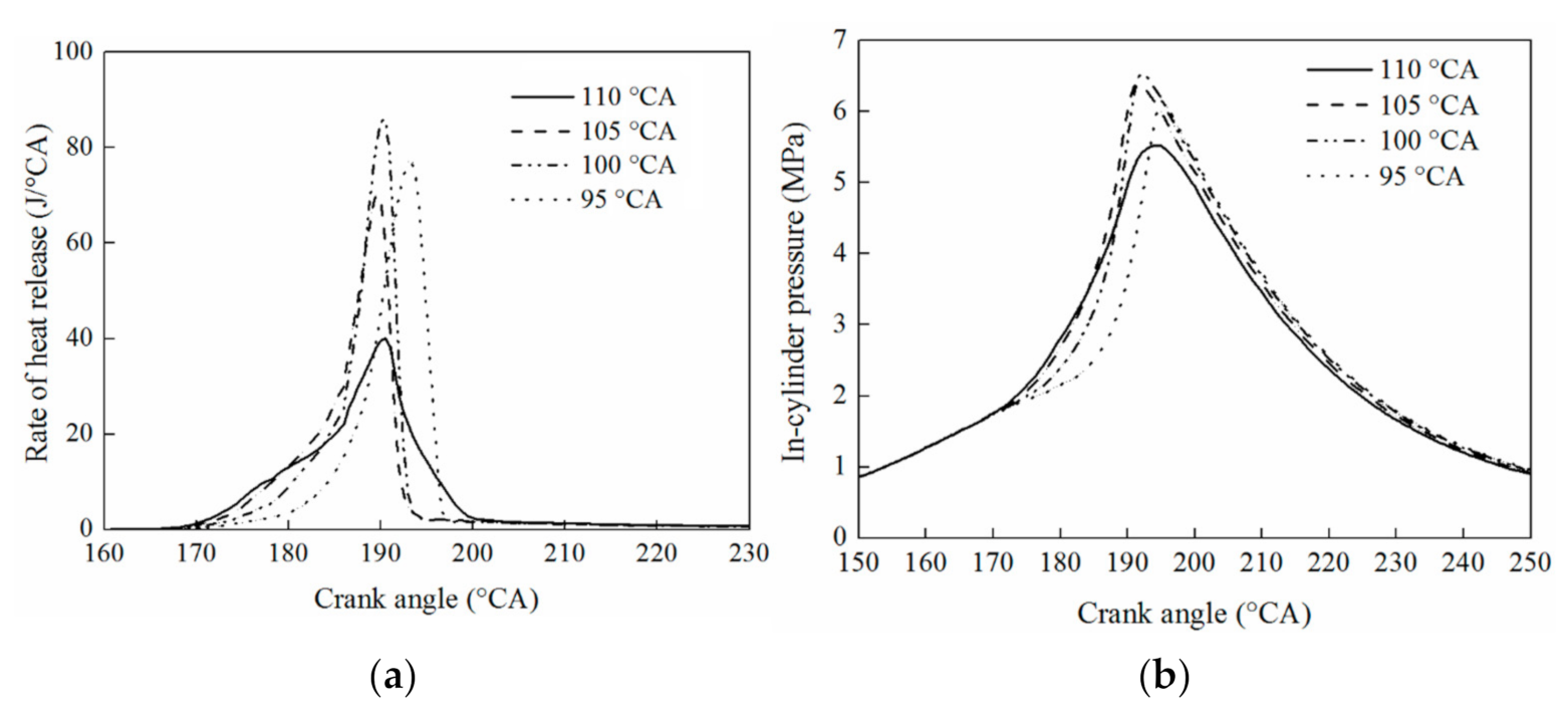
4.3. Effect of Injection Timing on Combustion Process

The combustion process in the cylinder is investigated with different injection advance angles when the ignition advance angle is 20 °CA. The combustion duration consists of two stages: the flame development period is the crankshaft angle experienced from spark to accumulative heat release up to 10%, and the rapid combustion period is the crankshaft angle experienced by accumulative heat release from 10% to 90%. The relationship between flame development period, rapid combustion period, and injection advance angle are shown in Figure 17. It can prove that with the increase of injection advance angle, the flame development period is gradually shortened, which is related to the distribution of mixture in the cylinder. With the advance of injection time, the mixing process of fuel and air becomes longer, which is conducive to the uniform mixing of fuel and air and promotes the formation of fire nucleus, thus shortening the flame development period. With the increase of injection advance angle, the flame development period decreases gradually, the rapid combustion period decreases first and then increases, and reaches the minimum value at the injection advance angle of 100 °CA, which means that the equivalence ratio distribution of the mixture is most suitable at this moment, the air utilization ratio is the highest and the flame propagation speed is the fastest.
The combustion process of the GDI engine is affected by the homogeneity of mixture and equivalent ratio, and it is bound to be affected by the different injection start times which have different effects on the motion state of the working fluid in the cylinder and the different flow patterns and equivalence ratios. The in-cylinder heat release rate and in-cylinder pressure are shown in Figure 18 when the ignition advance angle is 20 °CA. Figure 18a shows the comparison of combustion heat release rates for different injection advance angles. The heat release rates are lower when the injection advance angle is 110 °CA. The curves of heat release rates for the other three schemes are more consistent. With the decrease of injection advance angle, there is a maximum heat release rate, moreover, the heat release process moves back and the combustion heat release rate is the highest when the injection advance angle is 100 °CA. As shown in Figure 18b, the maximum in-cylinder pressure is different for the different combustion processes. The corresponding combustion pressure is the highest when the injection advance angle is 100 °CA.

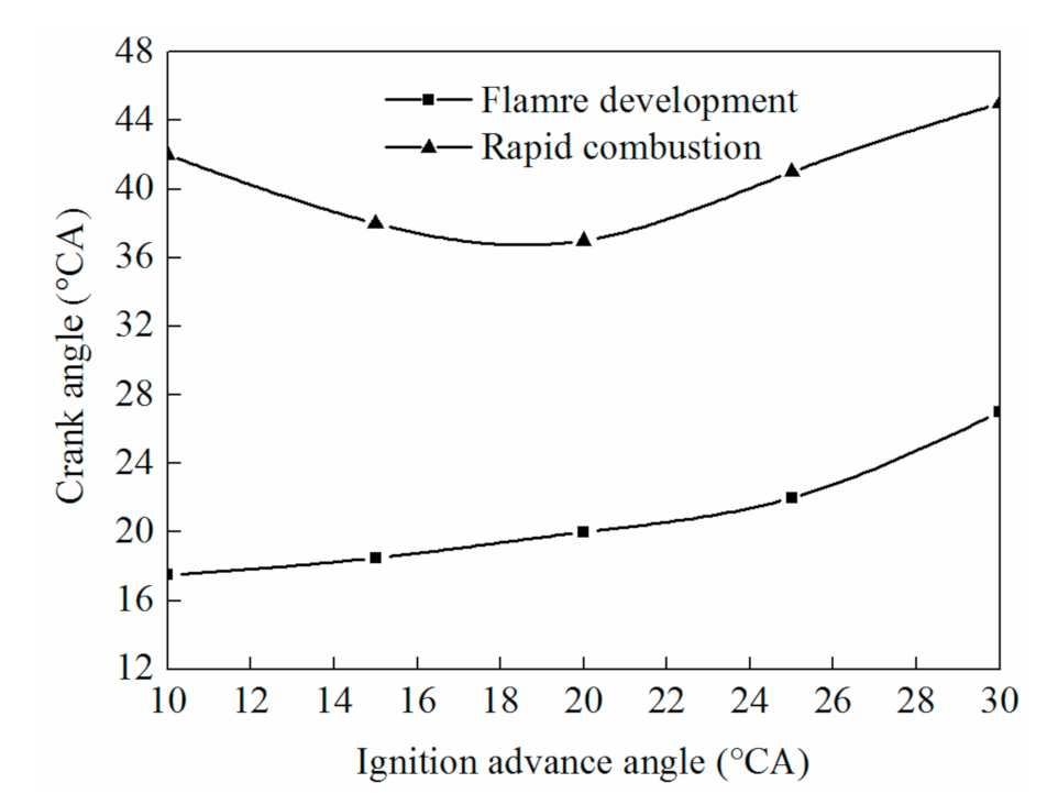
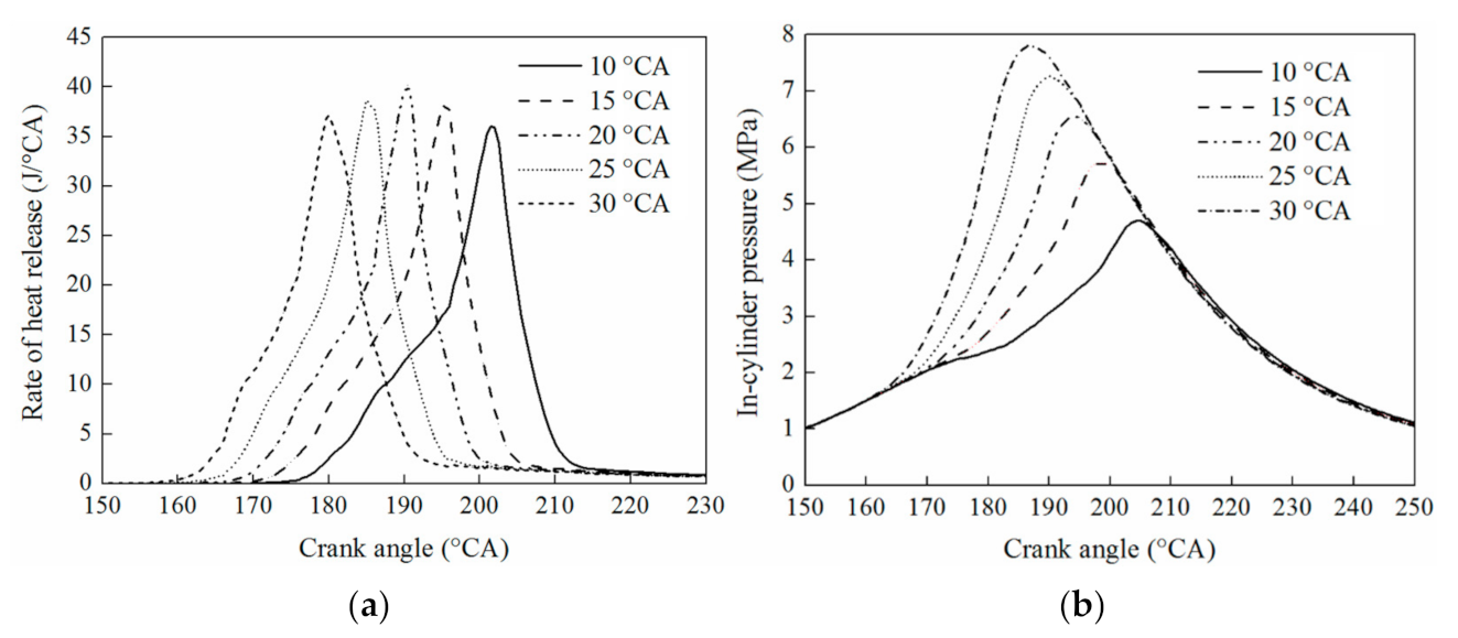
4.4. Effect of Ignition Timing on Combustion Process

When the injection advance angle is 100 °CA, the combustion process is studied by selecting different ignition advance angles. Figure 19 shows the flame development period and rapid combustion period at different ignition advance angles. The flame development period increases with the increase of ignition advance angle. On account of the decrease of ignition advance angle, the ignition timing of the mixture is delayed. The compression process of the mixture will own a greater proportion before ignition, which results in the increase of initial pressure and temperature before ignition, which is also conducive to the formation of flame core. Therefore, delayed ignition facilitates the rapid formation of the flame core in the cylinders of GDI engines. This is mainly due to the delay of ignition, on the one hand, increasing the mixing time of the working medium in the cylinder, which makes the mixing of fuel and air more complete and easier to ignite; on the other hand, the closer the opposing piston is from the inner dead center, the higher the compression degree of working medium in the cylinder is, the higher the corresponding temperature and pressure in the cylinder during ignition is, which contributes to the formation and development of the flame core. The combination of the two causes the flame development period to decrease with the delay of ignition timing.
At the same time, with the increase of ignition advance angle, the rapid combustion period first decreases and then increases, and reaches the minimum when the ignition advance angle is 20 °CA. If the ignition time is too early, relatively low temperature and pressure in the cylinder are not conducive to the rapid propagation of the flame, the rapid combustion period is prolonged. However, if ignition time is too late, the starting point of combustion gradually moves back, and the corresponding in-cylinder pressure and temperature for combustion of working substances in the cylinder are lower than that for pre-ignition. Lower temperature and pressure will delay the oxidation reaction in the cylinder, which is not conducive to the rapid propagation of flame [30]. Moreover, the backward start of combustion also causes the increase of the combustion proportion of the working medium in the cylinder during the expansion process. The movement of the opposing piston outward during the expansion process will increase the flame propagation distance and increase the flame propagation time.
As shown in Figure 20, it can be seen that with the increase of the injection advance angle, the combustion process will advance and the peak pressure in the cylinder will increase with the increase of the injection advance angle of 100 °CA. At the ignition advance angle of 20 °CA, there is a maximum instantaneous heat release rate. As the ignition timing is delayed, it is beneficial to increase the mixing time, improve combustion and increase the peak instantaneous heat release rate. However, with the further delay of ignition timing, the phase corresponding to the ignition start point moves back, the duration of combustion increases, and the flame propagation speed decreases, which causes the heat release process of working substance in the cylinder to be slow gradually, and the peak value of instantaneous heat release rate decreases and moves back, resulting in the decrease and backward peak value of in-cylinder pressure.

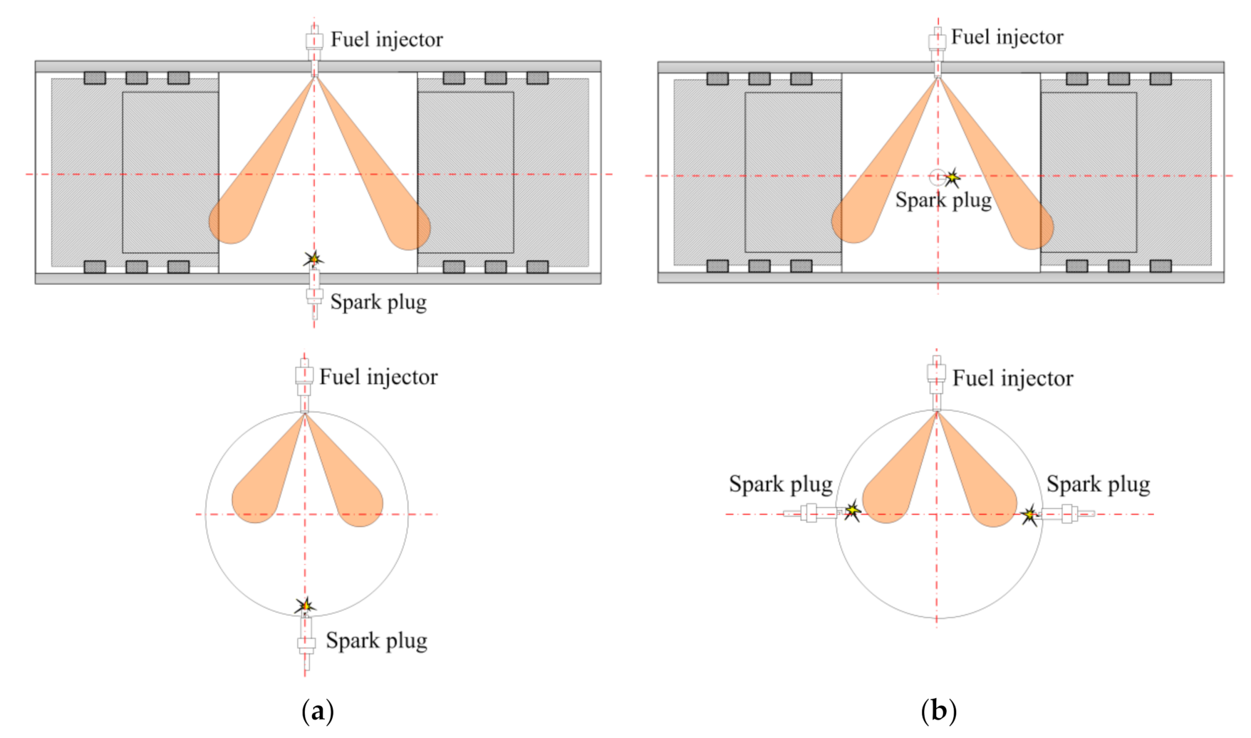
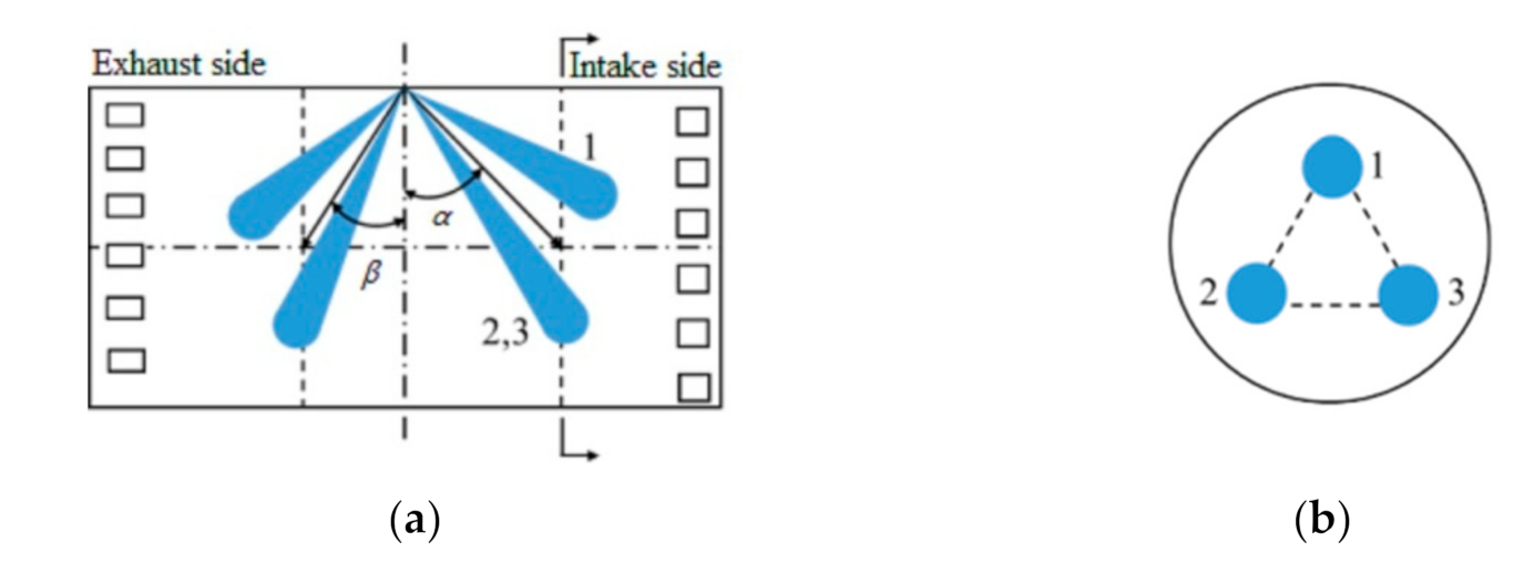
5. Study on Combustion Process of Dual Spark Plug Ignition

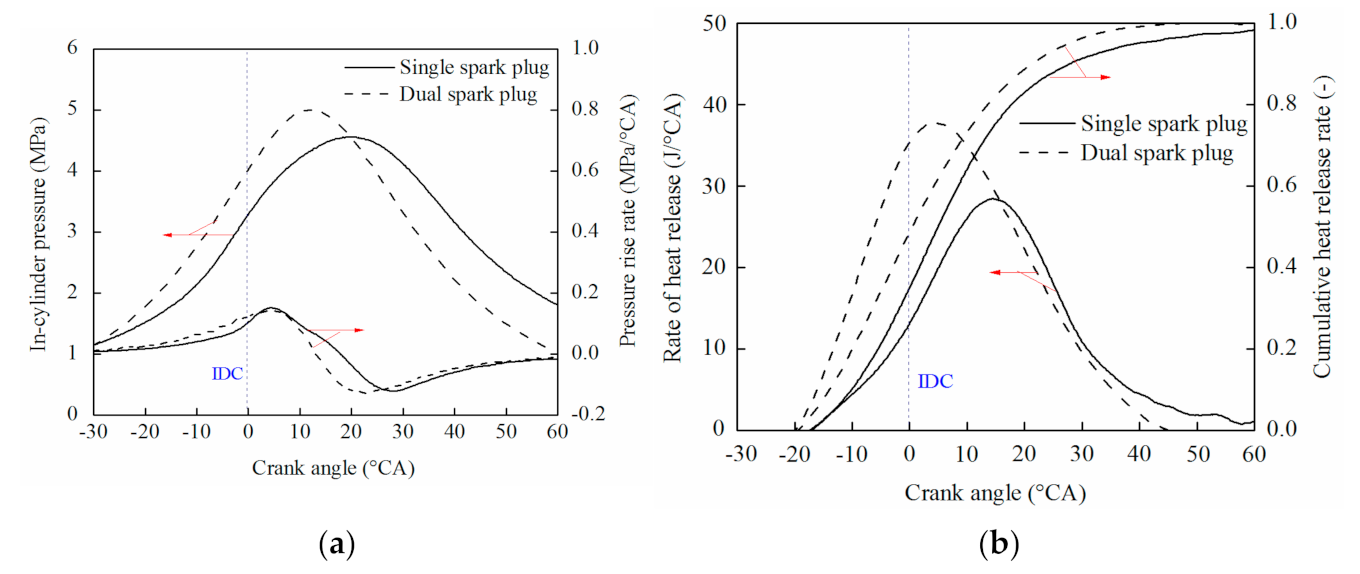
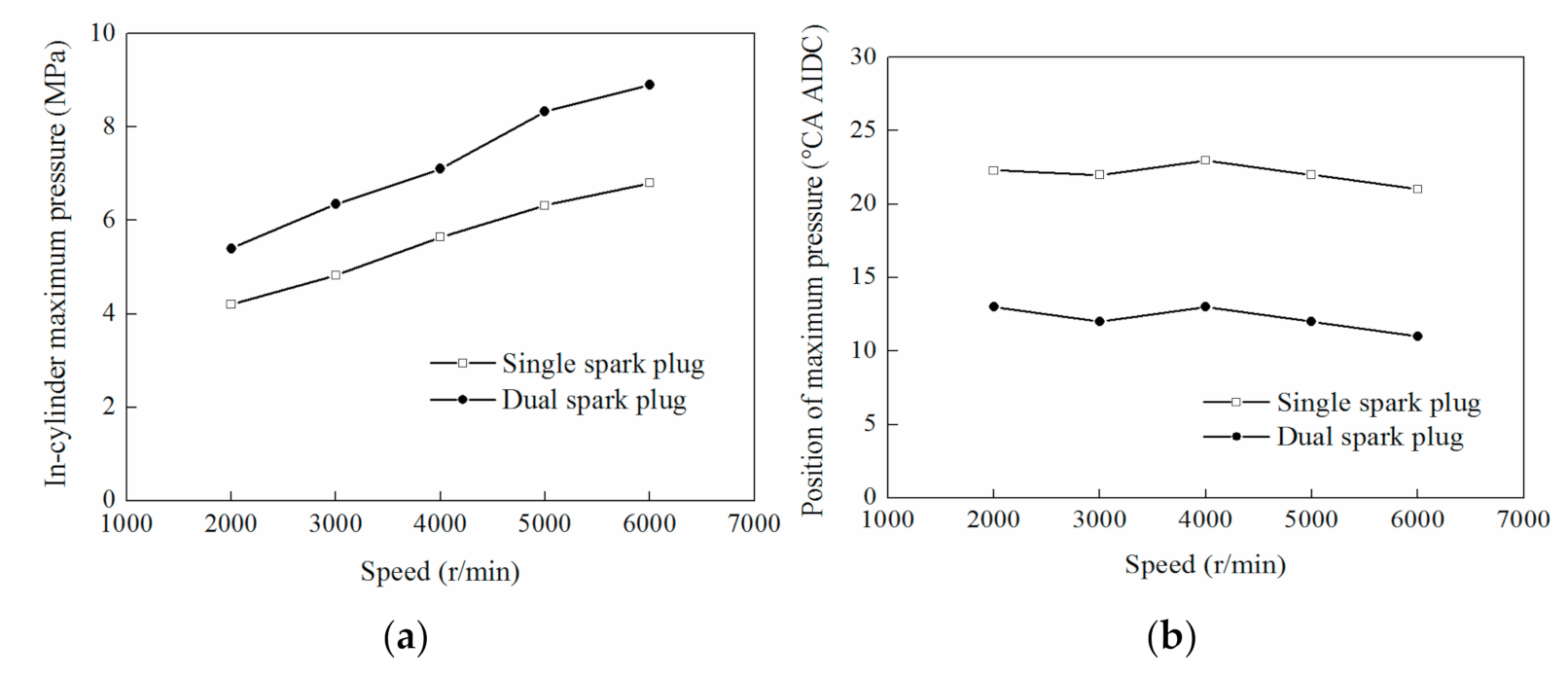
5.1. Contrast Experiments of Single and Dual Spark Plug

OP2S-GDI engine uses a spark plug on the sidewall of the cylinder liner to ignite. Compared with the combustion chamber of the traditional in-cylinder direct-injection gasoline engine, the ignition core offsets and flame propagation distance increase. Therefore, the ignition schemes of the single and dual spark plug are investigated, as shown in Figure 21.
Based on the characteristics of small bore and long stroke of opposed-piston two-stroke gasoline engine, and the arrangement of fuel injector on the sidewall of the cylinder liner, this paper designs the asymmetric spraying method on the intake and exhaust side with the cylinder center cross-section as the symmetry surface. As shown in Figure 22a, there are three sprays at the intake side and the exhaust side, respectively. The α and β are the angles between the cylinder center plane and center line of the three spray beams on the intake side and exhaust side respectively, which are defined as the spray angle. A cross-section is determined on the intake and exhaust side so that the landing points of the three sprays on the cross-section are distributed evenly, as shown in Figure 22b. The position of the cross-section is determined by the spray angle.
When the speed is 3000 rpm, the scavenging pressure is adjusted to 0.12 MPa, the phase difference of the opposing piston is 15 °CA, and the injection advance angle is 140 °CA. A flat-top piston is used to ignite with a single spark plug, and the opposed ignition with a double spark plug is used with a flat-top piston and the vertical arrangement with the injector. The ignition advance angle is 20 °CA. The combustion corresponding to different ignition modes is studied. When OP2S-GDI engine is ignited with a single spark plug arranged on the sidewall of the cylinder liner, the ignition core deviation and flame propagation distance of OP2S-GDI engine are larger than those of traditional gasoline engine, the combustion duration is prolonged, and the in-cylinder pressure and pressure lift rate are reduced, as shown in Figure 23a. At the same time, when OP2S-GDI is ignited by the single spark plug, there is an obvious afterburning phenomenon, the peak heat release rate of combustion decreases, and the combustion center of gravity is delayed, as shown in Figure 23b. Based on the characteristics of flat-top piston structure and spark plug arrangement in the cylinder liner sidewall of OP2S-GDI engine prototype, dual spark plug opposite ignition method is needed to accelerate flame propagation, to improve the combustion heat release rate.
Figure 24a shows the maximum in-cylinder pressure of the OP2S-GDI engine for the different speeds. A flat-top piston ignition scheme with dual spark plugs can effectively shorten the flame propagation distance. The maximum combustion pressure in the cylinder is about 1 MPa higher than that with single spark plug ignition [31,32]. At the same time, the maximum combustion pressure increases linearly with the increase of rotational speed. Figure 24b shows the position of the highest combustion pressure point in the cylinder of an OP2S-GDI engine for different speeds. By the dual spark plugs, the highest combustion pressure point in the cylinder is 11~14 °CA after the inner dead point, which is about 10 °CA ahead of the single spark plug ignition.

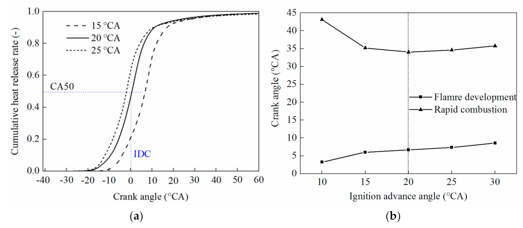
5.2. Rapid Combustion Characteristics of Dual Spark Plug

When the OP2S-GDI engine adopts a flat-top piston and double spark plug synchronous ignition scheme, different ignition advance angles are selected to analyze the influence of different ignition advance angles on the heat release process, as shown in Figure 25. With the increase of ignition advance angle, the flame development period prolongs, and the rapid combustion period decreases first and then increases, and reaches the minimum value at the ignition advance angle of 20 °CA. With the increase of ignition advance angle, the heat release rate in the cylinder increases gradually. The optimum center of combustion heat release can be achieved by choosing the ignition advance angle of 20 °CA, and the flame development period and combustion duration can be shortened at the same time.
At the same time, considering the influence of ignition advance angle on combustion exothermic process, the 20 °CA ignition advance angle can ensure the highest indicated thermal efficiency at medium and high loads and high indicated thermal efficiency at low loads, as shown in Figure 26. OP2S-GDI engine has a high heat release rate and an indicated thermal efficiency when the ignition advance angle is 20 °CA and the dual spark plug opposed ignition is used with the flat top piston. Therefore, it can be used as a scheme of the combustion chamber and ignition system of the OP2S-GDI engine.

6. Conclusions

(1)
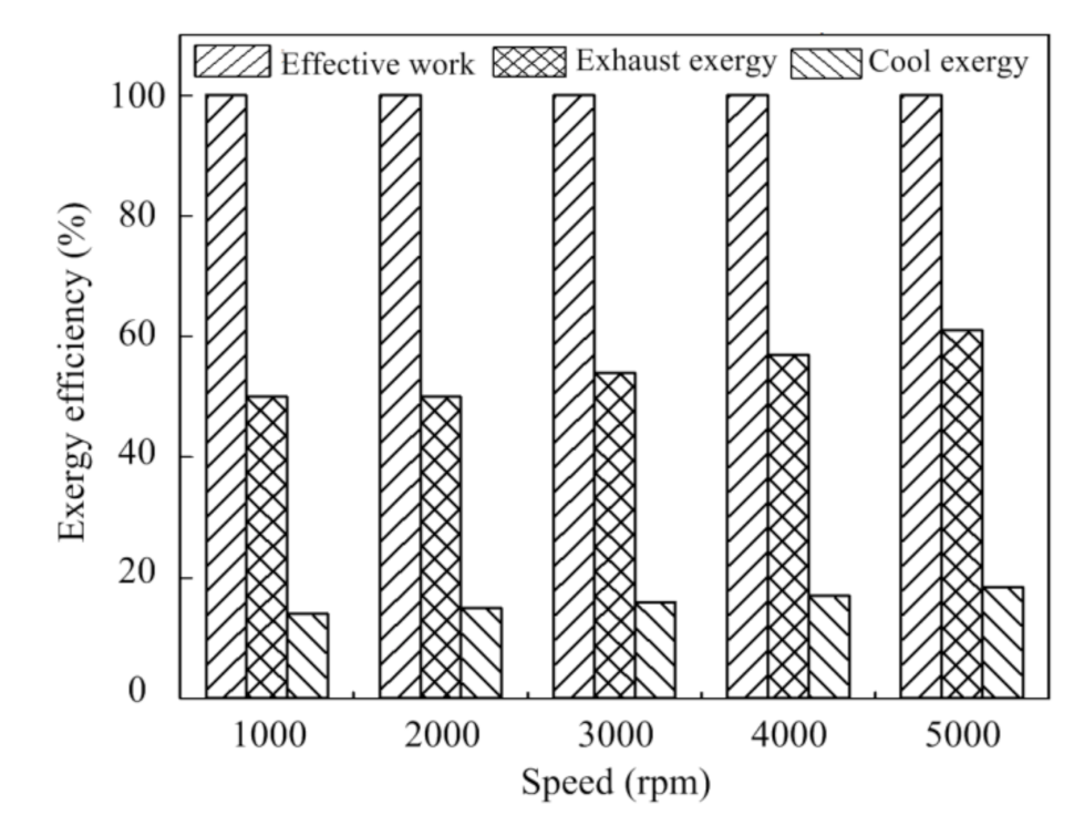
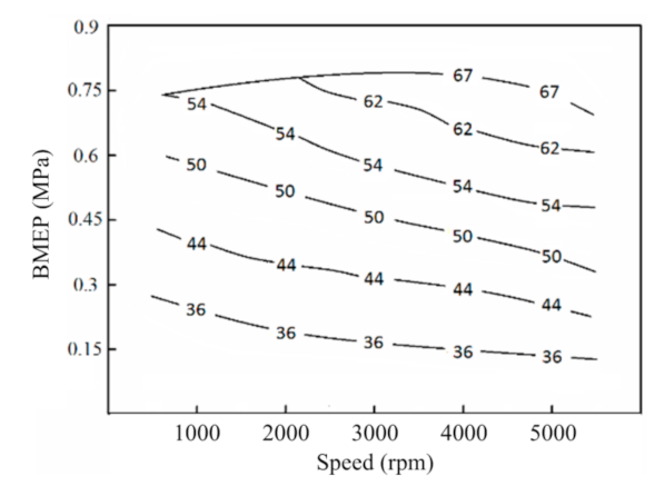
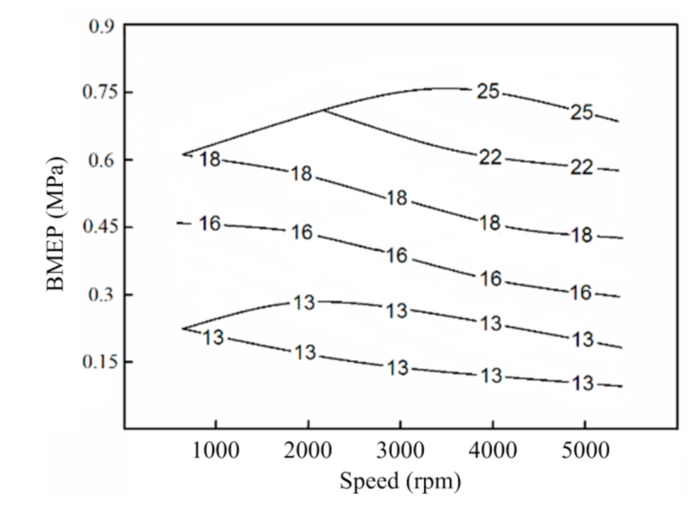
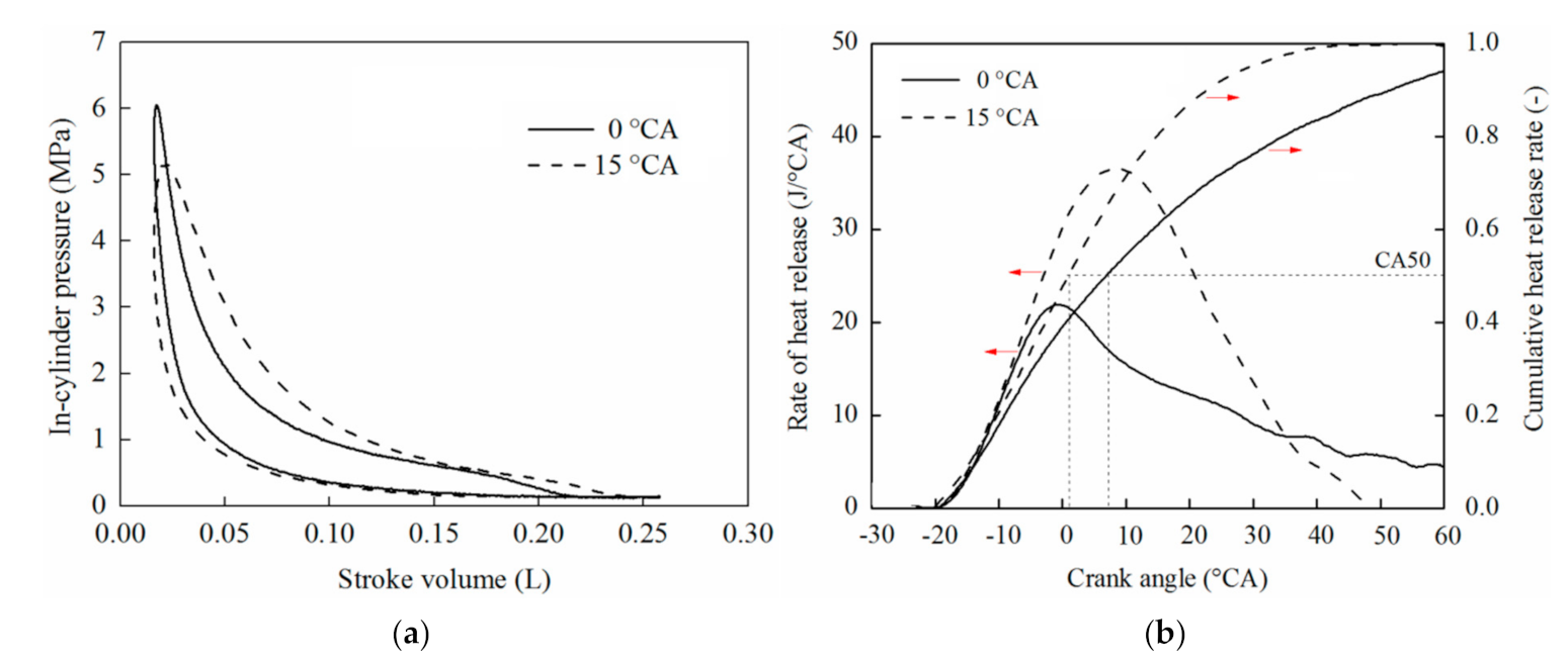
The heat release process of the OP2S-GDI engine is consistent with the traditional gasoline engine. The energy distribution of an OP2S-GDI engine is influenced by both load and speed. Exhaust energy is high under most operating conditions and about 1/3 of the total fuel energy is carried by the exhaust. The proportion of heat transferred to the cooling water is greater in the low load. The exhaust energy to fuel energy is more than 20%, which can be fully utilized to effectively improve fuel consumption.
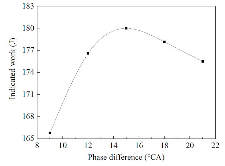
(2)
When the phase difference of the opposed piston is 15 °CA, the scavenging process can be improved, the combustion process can be accelerated. With the increase of rotational speed, it is necessary to increase the scavenging pressure. When the scavenging pressure is 0.12 MPa, the scavenging process and combustion organization at medium and high speed can be taken into account.
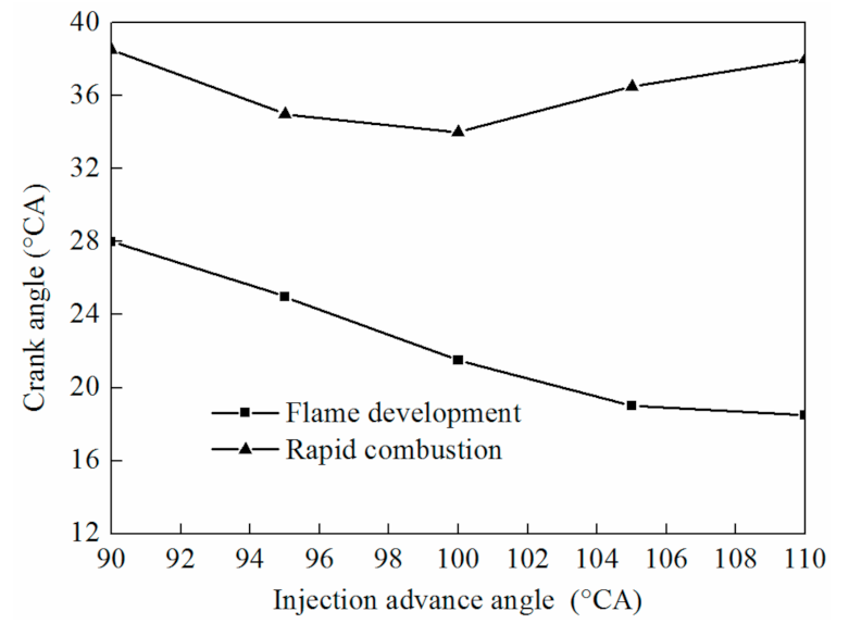
(3)
With the increase of injection advance angle, the flame development period is shortened, and the rapid combustion period decreases first and then increases. The rapid combustion period is the minimum value when the injection advance angle is 100 °CA.
(4)
The OP2S gasoline engine can achieve rapid in-cylinder combustion by the opposed dual spark plug ignition. When the ignition advance angle is 20 °CA, the highest heat release rate and indicated thermal efficiency can be achieved, which is the minimum value for the rapid combustion period.

Author Contributions

F.M. and W.Y. designed the experimental set-up; Z.Z. (Zhenfeng Zhao) and F.M. performed the experiment; Y.W. and Z.Z. (Zhenyu Zhang) analyzed the data; F.M. wrote the paper; J.X. and Y.L. performed the energy and exergy analyses. All authors have read and agreed to the published version of the manuscript.

Funding

This research was funded by the National Ministry Fundamental Research Foundation of China (grant no. B62201070215).

Institutional Review Board Statement

Not applicable.

Informed Consent Statement

Not applicable.

Data Availability Statement

Not applicable.

Acknowledgments

Authors are grateful to the National Ministry Fundamental Research Foundation of China (grant no. B62201070215) for the provision of funding.

Conflicts of Interest

The authors declare no conflict of interest.

Acronyms

BDCbottom dead center
BMEPBrake Mean Effective Pressure
CAcrank angle
CA1010% of the cumulative heat release
CA5050% of the cumulative heat release
CA9090% of the cumulative heat release
CFDcomputational fluid dynamics
CGPcylinder gas pressure
CRcommon rail
GDIgasoline direct injection
HCCIhomogeneous charge compression ignition
HRheat release
IMEPindicated mean effective pressure
IDCinner dead center
LTClow-temperature combustion
ODCouter dead center
OP2Sopposed-piston two-stroke
PCCIpremixed charge compression ignition
ROHRrate of heat release
rpmrevolution per minute
TDCtop dead center

References

  1. Kalghatgi, G. Development of Fuel/Engine Systems—The Way Forward to Sustainable Transport. Engineering 2019, 5, 510–518. [Google Scholar] [CrossRef]
  2. Naik, S.; Johnson, D.; Koszewnik, J.; Fromm, L.; Redon, F.; Regner, G.; Fuqua, K. Practical applications of opposed-piston engine technology to reduce fuel consumption and emissions. SAE Tech. Pap. 2013. [Google Scholar] [CrossRef]
  3. Hofbauer, P. Opposed piston opposed cylinder (opoc) engine for military ground vehicles. SAE Tech. Pap. Ser. 2005. [Google Scholar] [CrossRef]
  4. Pirault, J.P.; Flint, M.L.S. Opposed Piston Engines: Evolution, Use, and Future Applications; SAE International: Warrendale, PA, USA, 2009. [Google Scholar]
  5. Dong, X.; Zhao, C.; Zhang, F. Experimental study on the scavenging process of Opposed-Piston Two-Stroke diesel Engine. Trans. CSICE 2015, 4, 362–369. [Google Scholar]
  6. Ma, F.; Zhao, C.; Zhang, S.; Wang, H. Scheme Design and Performance Simulation of Opposed-Piston Two-Stroke Gasoline Direct Injection Engine. In SAE Technical Paper Series; SAE International: Deroit, MI, USA, 2015. [Google Scholar]
  7. Shokroll, F.; Alqahtani, A.; Wyszynski, M.L. Thermodynamic simulation comparison of opposed two-stroke and conventional four-stroke engines. Int. Congr. Combust. Engines 2013, 5, 24–26. [Google Scholar]
  8. Mattarelli, E.; Cantore, G.; Rinaldini, C.A.; Savioli, T. Combustion System Development of an Opposed Piston 2-Stroke Diesel Engine. Energy Procedia 2017, 126, 1003–1010. [Google Scholar] [CrossRef] [Green Version]
  9. Bo, T.; Clerides, D.; Gosman, A.D.; Theodossopoulos, P. Prediction of the Flow and Spray Processes in an Automobile DI Diesel Engine. SAE Int. Congr. Expo. 1997. [Google Scholar] [CrossRef]
  10. Franke, M.; Huang, H.; Liu, J.; Geistert, A.; Adomeit, P. Opposed Piston Opposed Cylinder (opoc™) 450 hp Engine: Performance Development by CAE Simulations and Testing. SAE World Congr. Exhib. 2006, 115, 196–203. [Google Scholar]
  11. Huo, M.; Huang, Y.; Hofbauer, P. Piston Design Impact on the Scavenging and Combustion in an Opposed-Piston, Opposed-Cylinder (OPOC) Two-Stroke Engine. SAE World Congr. Exhib. 2015. [Google Scholar] [CrossRef]
  12. Bebe, J.; Andersen, K. Validation of a CFD Spray Model Based on Spray Nozzle Characteristics. SAE World Congr. Exp. 2017. [Google Scholar] [CrossRef]
  13. Turner, J.W.G.; Head, R.A.; Chang, J.; Engineer, N.; Wijetunge, R.; Blundell, D.W.; Burke, P. 2-Stroke Engine Options for Automotive Use: A Fundamental Comparison of Different Potential Scavenging Arrangements for Medium-Duty Truck Applications. Int. Powertrains Fuels Lubr. Meet. 2019. [Google Scholar] [CrossRef]
  14. Cung, K.; Bitsis, D.C.; Briggs, T.; Kalaskar, V.; Abidin, Z.; Shah, B.; Miwa, J. Effect of Micro-Hole Nozzle on Diesel Spray and Combustion. WCX World Congr. Exp. 2018. [Google Scholar] [CrossRef]
  15. Redon, F.; Sharma, A.; Headley, J. Multi-Cylinder Opposed Piston Transient and Exhaust Temperature Management Test Results. SAE World Congr. Exhib. 2015. [Google Scholar] [CrossRef]
  16. Hassantabar, A.; Najjaran, A.; Farzaneh, G. Investigating the Effect of Engine Speed and Flight Altitude on the Performance of Throttle Body Injection (TBI) System of a Two-stroke Air-powered Engine. Aerosp. Sci. Technol. 2019, 86, 375–386. [Google Scholar] [CrossRef]
  17. Yang, W.; Li, X.-R.; Kang, Y.-N.; Zuo, H.; Liu, F.-S. Evaluating the Scavenging Process by the Scavenging Curve of an Opposed-piston Two-stroke Diesel Engine. Appl. Therm. Eng. 2019, 147, 336–346. [Google Scholar] [CrossRef]
  18. Ma, F.; Zhao, C.; Zhang, F.; Zhao, Z.; Zhang, Z.; Xie, Z.; Wang, H. An Experimental Investigation on the Combustion and Heat Release Characteristics of an Opposed-Piston Folded-Cranktrain Diesel Engine. Energies 2015, 8, 6365–6381. [Google Scholar] [CrossRef] [Green Version]
  19. Zhang, L.; Su, T.; Feng, Y.; Zhang, Y.; Ma, F.; Yin, J. Numerical Investigation of the Effects of Injection Interval of Split Injection Strategies on Combustion and Emission in an Opposed-Piston Opposed-Cylinder Two-Stroke Diesel Engine. J. Test Meas. Technol. 2018, 10, 684. [Google Scholar]
  20. Liu, Y.; Zhang, F.; Zhao, Z.; Cui, T.; Zuo, Z.; Zhang, S. The Effects of Pressure Difference on Opposed Piston Two Stroke Diesel Engine Scavenging Process. Energy Procedia 2017, 142, 1172–1178. [Google Scholar] [CrossRef]
  21. Heywood, J.B. Internal Combustion Engines Fundamentals; McGraw Hill International: New York, USA, 1988. [Google Scholar]
  22. Rakopoulos, C.D.; Giakoumis, E.G. Second-law analyses applied to internal combustion engines operation. Prog. Energy Combust. Sci. 2006, 32, 2–47. [Google Scholar] [CrossRef]
  23. Canakci, M.; Hosoz, M. Energy and exergy analyses of a diesel engine fuelled with various biodiesels. Energy Sources Part B Econ. Plan. Policy 2006, 1, 379–394. [Google Scholar] [CrossRef]
  24. Sayin Kul, B.; Kahraman, A. Energy and Exergy Analyses of a Diesel Engine Fuelled with Biodiesel-Diesel Blends Containing 5% Bioethanol. Entropy 2016, 18, 387. [Google Scholar] [CrossRef]
  25. Monsalve-Serrano, J.; Belgiorno, G.; Di Blasio, G.; Guzmán-Mendoza, M. 1D Simulation and Experimental Analysis on the Effects of the Injection Parameters in Methane–Diesel Dual-Fuel Combustion. Energies 2020, 13, 3734. [Google Scholar] [CrossRef]
  26. Da Costa, Y.J.R.; de Lima, A.G.B.; Filho, C.R.B.; de Araujo Lima, L. Energetic and exergetic analyses of a dual-fuel diesel engine. Renew. Sustain. Energy Rev. 2012, 16, 4651–4660. [Google Scholar]
  27. Sierens, R.; Rosseel, E. The computation of the apparent heat release for a hydrogen fueled engine. ASME Internal Combustion Engine Division 1996, 27, 120. [Google Scholar]
  28. Brunt, M.F.J.; Rai, H.; Emtage, A.L. The calculation of heat release energy from engine cylinder pressure data. SAE Tech. Pap. 1998, 981052. [Google Scholar] [CrossRef]
  29. Zhong, S.; Daniel, R.; Xu, H.; Zhang, J.; Turner, D.; Wyszynski, M.L.; Richards, P. Combustion and emissions of 2, 5-dimethylfuran in a direct-injection spark-ignition engine. Energy Fuels 2010, 24, 2891–2899. [Google Scholar] [CrossRef]
  30. Huang, Y.; Wang, Z.; Wang, J. Effects of Injection Timing on Particulate Emission in Gasoline Direct Injection Engine. Trans. CSICE 2014, 32, 420–425. [Google Scholar]
  31. Duan, X.; Deng, B.; Liu, Y.; Li, Y.; Liu, J. Experimental study the impacts of the key operating and design parameters on the cycle-to-cycle variations of the natural gas SI engine. Fuel 2021, 290, 119976. [Google Scholar] [CrossRef]
  32. Ma, F.; Zhao, C.; Zhang, S. Study on Dual-Spark Ignition Rapid Combustion Characteristic of Opposed-Piston Two-Stroke GDI Engine. Energy Procedia 2014, 61, 722–725. [Google Scholar] [CrossRef] [Green Version]
Figure 1. Configuration of the opposed-piston two-stroke gasoline direct injection (OP2S-GDI) engine: (a) section of OP2S-GDI engine, (b) opposed crank-connecting rod mechanism.
Energies 14 02105 g001
Figure 2. Testbed of OP2S-GDI engine: (a) front view, (b) back view.
Energies 14 02105 g002
Figure 3. The OP2S-GDI engine experimental system.
Energies 14 02105 g003
Figure 4. In-cylinder pressure and temperature.
Energies 14 02105 g004
Figure 5. The heat release rate and the cumulative rate of heat release.
Energies 14 02105 g005
Figure 6. Percentage of effective work in total energy.
Energies 14 02105 g006
Figure 7. Percentage of exhaust gas energy in total energy.
Energies 14 02105 g007
Figure 8. Percentage of cooling water energy in total energy.
Energies 14 02105 g008
Figure 9. Exergy efficiency.
Energies 14 02105 g009
Figure 10. Percentage of exhaust gas energy in exhaust gas energy.
Energies 14 02105 g010
Figure 11. Percentage of exhaust gas energy in total energy.
Energies 14 02105 g011
Figure 12. Opposed piston displacement.
Energies 14 02105 g012
Figure 13. Effect of phase difference on in-cylinder pressure and heat release rate: (a) in-cylinder pressure, (b) heat release rate.
Energies 14 02105 g013
Figure 14. Effect of phase difference on indicated work.
Energies 14 02105 g014
Figure 15. Effect of scavenging pressure on in-cylinder pressure and pressure rise rate: (a) scavenging pressure is 0.11 MPa, (b) scavenging pressure is 0.12 MPa.
Energies 14 02105 g015
Figure 16. Effect of scavenging pressure on heat release rate and the cumulative rate of heat release: (a) scheme 0. 11 MPa; (b) scavenging pressure is 0.12 MPa.
Energies 14 02105 g016
Figure 17. Effect of injection timing on combustion duration.
Energies 14 02105 g017
Figure 18. Heat release rate and in-cylinder pressure of different injection timing: (a) heat release rate; (b) in-cylinder pressure.
Energies 14 02105 g018
Figure 19. Effect of ignition timing on combustion duration.
Energies 14 02105 g019
Figure 20. Heat release rate and in-cylinder pressure of different ignition timing: (a) heat release rate, (b) in-cylinder pressure.
Energies 14 02105 g020
Figure 21. The ignition schemes of the single and dual spark plug: (a) single spark plug ignition, (b) dual spark plug ignition.
Energies 14 02105 g021
Figure 22. Spray direction distribution: (a) in lengthwise section, (b) in cross-section.
Energies 14 02105 g022
Figure 23. Effect of ignition scheme on in-cylinder pressure and heat release rate: (a) in-cylinder pressure, (b) heat release rate.
Energies 14 02105 g023
Figure 24. Comparison between in-cylinder pressure of single and dual spark plug: (a) in-cylinder maximum pressures, (b) position of maximum pressures.
Energies 14 02105 g024
Figure 25. Effect of ignition timing on combustion process: (a) cumulative rate of heat release, (b) combustion duration.
Energies 14 02105 g025
Figure 26. Comparison between thermal efficiency of different ignition timing.
Energies 14 02105 g026
Table 1. OP2S-GDI engine specifications.
Structure ParametersValue
Bore (mm)56
Stroke (mm)49.5 (×2)
Connecting rod (mm)82.5
Effective compression Ratio (-)10.5
Engine speed (rpm)5000
Number of intake ports (-)10
Number of exhaust ports (-)10
Intake port height stroke ratio (-)0.121
Exhaust port height stroke ratio (-)0.141
Intake port circumference ratio (-)0.75
Exhaust port circumference ratio (-)0.6
Opposed-piston phase difference (°CA)15
Intake port radial angle (°)15
Exhaust port radial angle (°)0
Power (kW)15
Fuel consumption rate (g/kW h)276
Table 2. The model and specification of the test instrument.
NameModelSpecification
Control systemEcotrons NA2T1C250 ccSupporting platform
Control softwarePro CAL softwareProgrammable controller
Cylinder pressure sensor6056AKistler Instrumente AG, 0.25 °CA resolution
Crankshaft position sensorKistler 2614B0.2 °CA sampling precision
Fuel consumption instrumentWeighing type FCH-2210Measurement time range 1–200 s
Engine dynamometerCW25Test accuracy is ±0.2~0.3% FS and ±1 rpm
Publisher’s Note: MDPI stays neutral with regard to jurisdictional claims in published maps and institutional affiliations.

