Article

A GaN-HEMT Compact Model Including Dynamic RDSon Effect for Power Electronics Converters

1
Centre for Advanced Low-Carbon Propulsion Systems, Coventry University, Coventry CV1 2TL, UK
2
Power Electronics, Machines and Control Group, University of Nottingham, Nottingham NG7 2RD, UK
3
Laboratoire d’Electrotechnique et d’Electronique de Puissance, Université de Lille, Centrale Lille, Junia, ULR 2697, Arts et Metiers Institute of Technology, F-59000 Lille, France
*
Author to whom correspondence should be addressed.
These authors contributed equally to this work.
Energies 2021, 14(8), 2092; https://doi.org/10.3390/en14082092
Submission received: 26 February 2021 / Revised: 1 April 2021 / Accepted: 3 April 2021 / Published: 9 April 2021
(This article belongs to the Special Issue Wide Bandgap Semiconductors and Their Applications)

Abstract

:
In order to model GaN-HEMT switching transients and determine power losses, a compact model including dynamic R DSon effect is proposed herein. The model includes mathematical equations to represent device static and capacitance-voltage characteristics, and a behavioural voltage source, which includes multiple RC units to represent different time constants for trapping and detrapping effect from 100 ns to 100 s range. All the required parameters in the model can be obtained by fitting method using a datasheet or experimental characterisation results. The model is then implemented into our developed virtual prototyping software, where the device compact model is co-simulated with a parasitic inductance physical model to obtain the switching waveform. As model order reduction is applied in our software to resolve physical model, the device switching current and voltage waveform can be obtained in the range of minutes. By comparison with experimental measurements, the model is validated to accurately represent device switching transients as well as their spectrum in frequency domain until 100 MHz. In terms of dynamic R DSon value, the mismatch between the model and experimental results is within 10% under different power converter operation conditions in terms of switching frequencies and duty cycles, so designers can use this model to accurately obtain GaN-HEMT power losses due to trapping and detrapping effects for power electronics converters.

1. Introduction

During the last few years, research interest to apply gallium nitride (GaN) high-electron-mobility transistors (HEMT) for power electronics converters has been increasing rapidly for different applications in railway [1] and automotive engineering [2]. In terms of power level, they cover the applications from below 48 V DC-DC converter [3] to above 10 kW three-phase DC-AC inverter [4]. GaN-HEMT can operate at higher switching frequency and efficiency than silicon or silicon carbide (SiC) counterparts for below 600 V electrical energy conversion [5]. As a result, they can be widely applied in different power converter topologies, such as multi-phase converter for integrated motor drive, bidirectional converter for e-mobility and power factor correction (PFC) converter for charger. However, voltage and current switching transients of GaN-HEMT can exceed 100 V/ns and 1 A/ns, respectively, which brings the challenge on power converters design to minimise gate voltage, drain voltage overshoot and stability. Another well-noted challenge is thermal management for GaN-HEMT. As device chip area is reduced, and it is usually surface-mounted in packaging, cooling becomes more difficult than conventional TO-type packaging. For this reason, it is necessary to accurately estimate device power losses for its safe operation.
In order to resolve the above challenges, it is important to have an easy-to-use device model to represent both switching transients and ON-state resistance accurately and rapidly. In terms of device switching transients, it requires not only a device model to represent its ON-state characteristics and nonlinear capacitance, but also an accurate estimation of electrical circuit parasitic elements due to interconnections [6]. A conventional approach is that in an electrical circuit simulator (e.g., Spice), designers import device compact model (self developed or from device manufacturer) and lumped model for parasitic inductance and resistance, which are extracted by using 3D simulation software based on finite element method (FEM) or partial element equivalent circuit (PEEC). This approach was applied by Liu et al. to model a cascode GaN transistor [7], by Endruschat et al. to model a GaN-HEMT [8] and by Liang et al. to model a SiC-MOSFET [9], where the extracted parasitic inductance value varies from sub-nanoHenry to a fews tens of nano-Henry. However, one drawback of this approach is its crude representation of electromagnetic (EM) physics and the accuracy for the required values is in the range of nano-Henry. In order to have better insights for EM physics, the authors of [10] proposed a GaN-HEMT model integrated into a 3D simulation software (ADS). However, depending on the required mesh size, it may take designers long computation time (range of hours) to obtain device switching waveforms at one operation condition, which is not practical to compare different designs. In terms of device ON-state resistance ( R DSon ), GaN-HEMT suffers from trapped charge in device structure which would increase its dynamic R DSon in operation. These trapped charge are influenced by different parameters such as OFF-state [11] and ON-state time [12], voltage [13], switching losses [14], junction temperature [15] as well as device switching conditions [16] and frequency [17], which makes device dynamic R DSon difficult to predict. Note that in the above publications, GaN-HEMT dynamic R DSon is usually obtained by double pulse or multiple pulse method, which do not represent dynamic R DSon values in steady state, as GaN-HEMT trapping time constant can reach more than 100 s. For this reason, it is important to have a GaN-HEMT dynamic R DSon model to predict accurately device losses. However, most GaN-HEMT dynamic R DSon models are physical models for prediction of the trapped charges location in device structure [18], which is hard to be applied for power electronics converters.
Therefore, we propose a GaN-HEMT compact model including trapping effect in this paper, where our main contributions are as follows:
(1)
This compact model is integrated into our developed Power Electronics Virtual Prototyping (PEVP) design tool, which takes consideration of electrical circuit EM analysis by PEEC method. In comparison with the above-discussed approaches, one advantage is that it is applied model order reduction (MOR) for PEEC method, which is able to reduce the numbers of equations for EM analysis so as to obtain device switching transients in the range of minutes. It helps designers to save simulation time as discussed above.
(2)
The compact model also includes device dynamic R DSon values, which can be applied into different circuit simulators for power electronics converters. It helps designers to accurately obtain device losses in simulation as most GaN-HEMT model do not include dynamic R DSon effect for power electronics converters.
In comparison with our initial results published in [19], more experimental results on device switching transients are added in this paper.
The paper is structured with the following sections. In Section 2, a GaN-HEMT compact model used in the PEVP tool is presented. Simulation results are then compared with experimental measurements. In Section 3, GaN-HEMT dynamic R DSon is represented by an equivalent circuit, in which the process to extract the required parameters is explained. Then, dynamic R DSon is validated by experimental results. The article is concluded in Section 4.

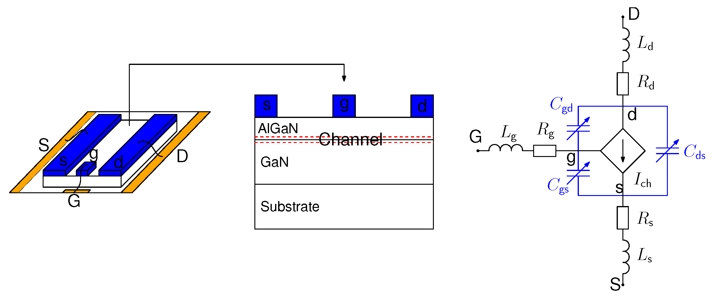
2. GaN-HEMT Compact Model

2.1. Model Principle

In Figure 1, a simplified structure of packaged GaN-HEMT and its compact model formed by equivalent circuit is presented. Note that GaN-HEMT is a lateral device, where the channel can be modelled by a V ds and V gs controlled bidirectional current source I ch . Device interelectrode capacitance C gd , C ds and C gs can be modelled by nonlinear capacitance, which is dependent on the voltage across each terminal. Finally, parasitic resistance and inductance are added for interconnection between device terminals and packaging pads. Even though this is a compact model, GaN-HEMT semiconductor physics is still included in the equivalent circuit.
A 650 V/7.5 A GaN-HEMT from GaNSystem (GS66502B) is modelled. I ch is represented by Equation (1) for both forward and reverse conduction. Required parameters are given in Table 1. Note that Equation (1) and the parameters are the same as those used in the GaNSystem GS66502B LTspice model. The comparison between model and datasheet values (Rev180420 [20]) for device ON-state characteristics is illustrated in Figure 2, where it is shown that device I D V DS characteristics are presented precisely by model in both 1st and 3rd quadrant. Note that in order to obtain V DS voltage, the voltage drop across parasitic resistance R d and R s need to be added to V ds voltage of Equation (1). R d = 0.17 Ω and R s = 0.009 Ω are used, which are the same as device manufacturer LTspice model.
I ch = a log 1 + exp b 1 V gs c · V ds 1 + m a x d + e · V gs + f 1 , 0.2 · V ds V ds 0 I ch = a log 1 + exp b 2 V gs V ds c · V ds 1 m a x d + e · V gs V ds + f 2 , 0.2 · V ds V ds < 0
Interelectrode capacitance C gs , C gd and C ds are represented by Equation (2) [21], where the used parameters are given in Table 2. Those equations are inspired by Sigmoid-type functions used to model power semiconductor devices static characteristics and capacitance-voltage characteristics [22,23]. We modified tangent hyperbolic functions to represent strong nonlinearity voltage dependence of each interelectrode capacitance, where we can define the variation boundary (parameters b n , e n and h n ), variation trend (parameters c n , f n and i n ) and variation centre ( d n , g n and j n ). Three terms are used to represent the observed nonlinear capacitance values in several voltage segments:
C gs =   a 1     b 1 1 + tanh c 1 V gs + d 1     e 1 1 + tanh f 1 V gs + g 1   +   h 1 1 + tanh i 1 V gs + j 1 C gd =   a 2     b 2 1 + tanh c 2 V gd + d 2   +   e 2 1 + tanh f 2 V gd + g 2     h 2 1 + tanh i 2 V gd + j 2 C ds =   a 3     b 3 1 + tanh c 3 V ds + d 3     e 3 1 + tanh f 3 V ds + g 3     h 3 1 + tanh i 3 V ds + j 3
The comparison between the model and datasheet for device C iss , C oss and C rss variation in respect to V DS voltage ( V GS = 0 V) is shown in Figure 3a, and that between model and experiment for C gs - V GS variation is presented in Figure 3b, where the experiment results are obtained by 2-port vector network analyser characterisation using S-parameters [10]. It can be concluded that device interelectrode capacitance values are represented precisely in the compact model. The presented GaN-HEMT model will then be implemented into our developed PEVP software.

2.2. Model Implementation into Power Electronics Virtual Prototyping Software

The used simulation techniques in PEVP software are summarised in Figure 4. There are in general two models that can be used for different components in power electronics converters. For example, for the represented half-bridge leg, it is formed by two power semiconductor devices S1 and S2 with their gate drivers, decoupling capacitor C decp , power supply V and PCB tracks for interconnections. For components such as power semiconductor devices, gate driver, C decp and V, power electronics engineers are interested in their characteristics. Therefore, the compact model described by equivalent circuits is suitable in simulation to obtain results quickly. For components like the PCB track or other interconnections, their layout and material properties are important for the design, as they directly influence power electronics converters parasitic inductance ( L para ) values. Therefore, the physical model described by component geometry is suitable in simulation to obtain results accurately.
In PEVP, the physical model used for the electromagnetic simulation is determined by PEEC method. Meshing is first applied to generate large numbers of original equations. Afterwards, a Model Order Reduction (MOR) method based on the PRIMA algorithm is used to reduce the numbers of equations; therefore, simulation speed can be accelerated. As compact models are represented by equivalent circuits, they are linked with physical model via electrical boundaries for time domain co-simulation in PEVP. Electrical waveforms can then be obtained. More details on the structure of PEVP and its use for electromagnetic and electro-thermal simulation can be found in our previous work [24,25].
As shown in Figure 5a, a GaN-HEMT (GS66502B) half-bridge circuit is built to measure device switching waveforms. The circuit is also modelled in PEVP, in which the presented modelling approach is used. As illustrated in Figure 5b, the PCB track is physically modelled with its real geometry, and then meshed in PEVP. Devices S1 and S2 are modelled by the presented compact model. The device gate driver, C decp , and load inductor, L out , are modelled by their equivalent circuits.
As shown in Figure 5b, gate loop inductance L gate and power loop inductance L power have an important impact on device switching transients. Their values are first extracted in PEVP via frequency domain simulation, and their variation with frequency is then presented in Figure 5c. It can be seen that both L gate and L power slightly decrease with frequency, illustrating the impact of skin effect and proximity effect. The obtained average L gate and L power between 10 and 100 MHz are then compared with another commercial software ADS [10] in Table 3, where it validates the accuracy of PEVP for electromagnetic simulation. Note that the simulation time to obtain these results in PEVP (60 points/decade from 1 kHz to 100 MHz) is within 1 min (25 s for meshing and 17 s for MOR), which is much reduced compared to ADS. We understand that full EM simulation in ADS give comprehensive results including capacitive coupling between each node, and this comparison in Table 3 is only to demonstrate the advantage of using MOR in PEVP, which meets our objective to obtain device switching waveforms quickly. In the next subsection, those reduced order models for L gate and L power (rather than one single value) will be used in time domain simulation to obtain GaN-HEMT switching waveforms.

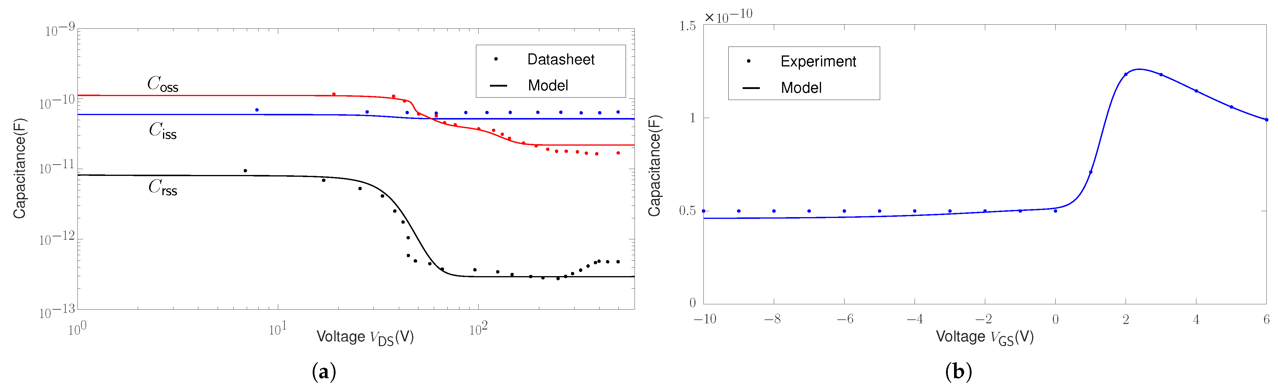
2.3. Model Validation

A comparison between the experimental measurement and simulation for switching current I D and voltage V DS under 200 V/4 A is presented in Figure 6. They have been measured by a 1 GHz current shunt and a 4 kV/400 MHz passive voltage probe to have sufficient large bandwidth and voltage-frequency attenuation. In terms of turn-OFF switching, the model matches well with the measurement for both d i /d t and d v /d t . In terms of turn-ON switching, the observed mismatch is mainly on attenuation of a 270 MHz resonance and V DS voltage drop due to L para d i d t . This is supposedly due to having an inaccurate model of effective resistance at such high frequency (270 MHz). A finer mesh size can be used in the simulation to improve model accuracy, but at the cost of computation time. Another factor which may lead to this mismatch is the measurement probe. Both current shunt and passive voltage probe bring the ground connection to the measurement circuit, which creates a complex common-mode loop that may interfere with device switching loop, bringing common-mode noise in the measurement results. Despite that, the model still matches well with the measurement for both d i /d t and d v /d t .
Based on the above waveforms, device turn-ON and turn-OFF switching energy ( E sw , ON , E sw , OFF ) are obtained and compared in Table 4. The difference between simulation and measurement is around 1 μ J, which confirms the accuracy of the model to estimate device switching losses.
The above I D and V DS transient waveforms are then converted into frequency domain by FFT to compare their magnitude. A Blackman window function was used to extract I D and V DS magnitude for turn-ON and turn-OFF. As turn-ON and turn-OFF transient time ( τ ) is between 5 and 10 ns, the magnitude above 10 MHz is therefore compared, which corresponds to the switching transients ( 1 τ π ). The results are then illustrated in Figure 7. For turn-ON switching, the magnitude obtained in the simulation matches well with the measurement above 100 MHz, and resonance frequency at 270 MHz was accurately modelled in the simulation. For turn-OFF switching, the magnitude obtained in the simulation matches well with the measurement until 100 MHz. Therefore, it can be concluded that both GaN-HEMT switching transients and switching loop L para are accurately modelled.
In the next section, a compact model will be presented to model device dynamic R DSon effect due to current collapse.

3. GaN-HEMT Dynamic R DSon Compact Model

It can be summarised from the literature that there are two origins of GaN-HEMT dynamic R DSon [26]: the V DS bias effect, which is associated with device operation when it is in OFF-state, and the hot electron effect, which is associated with device switching transients (overlapping of I D and V DS ). As commercial GaN-HEMT is driven by V GS = 6 V in power electronics converters, the impact of threshold voltage V th shift for dynamic R DSon can be almost neglected [27]. In this section, GaN-HEMT dynamic R DSon characterisation and modelling when the device is operated under zero voltage soft switching (ZVS) will be presented. Soft turn-ON is used in preference to hard switched turn-ON for the following reasons: (1) as presented in Table 4, GaN-HEMT E sw , ON is higher than E sw , OFF . Therefore, device total switching losses can be greatly reduced under soft switching, so as to operate device in higher switching frequency, which is close to device application for high power density power converters. (2) Due to hot electron effect, dynamic R DSon can be greatly reduced and device junction temperature can be easily controlled in soft switching. Therefore, the V DS bias effect can be studied with little interference.

3.1. Model Principle and Parameters Extraction

The V DS bias effect on the GaN-HEMT dynamic R DSon value can be illustrated in Figure 8. At each switching cycle T, during the OFF-state ( ( 1 D ) T ), the charge will be trapped by V DS bias voltage in device structure, which will increase its R DSon value when it is in ON-state ( D T ). This is known as the trapping effect. Then, during the ON-state, those trapped charges will be gradually released, therefore the device R DSon value will decrease towards its static value. This is known as the detrapping effect. In order to model the device dynamic R DSon value for power electronics converters, it is necessary to obtain dynamic R DSon trapping and detrapping time constants.
Dynamic R DSon of the presented GaN-HEMT is then measured by a proposed electrical circuit shown in Figure 9a. There are mainly two parts in this circuit: device switching circuit (DSC) and voltage clamping circuit (VCC). DSC and DUT form a standard H-bridge circuit. Under the control signal given in Figure 9b (control signals of T2 and T3 are complementary to those of T1 and DUT), DUT hard or soft switching conditions as well as its OFF-state ( t off ) and ON-state time ( t on ) can be precisely controlled. t off can be precisely controlled at interval t 1 t 2 . As DUT is under ZVS soft switching at t 2 by negative drain current, t on includes its reverse ( t 2 t 3 ) and forward conduction ( t 3 t 4 ). For VCC, its function is to reduce measurement voltage V DS ( m . ) when DUT is in OFF-state, so as to increase measurement resolution for its ON-state voltage V DSon by using a 8–12 bit oscilloscope. When DUT is in the OFF-state, depletion MOSFET M 1 voltage Δ V V DC ; therefore, a small voltage of a few volts which is equal to Zener diode Z 1 Zener voltage is measured. When DUT is in the ON-state under both reverse and forward conduction, Δ V = 0 , which guarantees accurate measurement of V DSon ( V DSon = V DS ( m . ) ). Device dynamic R DSon is then obtained by R DSon = V DS ( m . ) I D . More details on the measurement accuracy of the proposed measurement circuit can be found in our previous publication [28]. In this paper, we focus on the use of this measurement circuit to extract parameters for GaN-HEMT dynamic R DSon model.
When V DC = 200 V, device dynamic R DSon values under different t off are presented in Figure 10a, where dynamic R DSon values are quickly obtained within 50 ns after device V GS reaches ON-state gate voltage (6 V). This result illustrates the trapping effect on device dynamic R DSon value. It is observed that dynamic R DSon quickly increased more than 25% after 100 μ s bias time. Then, it increases slowly with t off until 1 s. From 1 s to 10 s, dynamic R DSon increase rapidly until 70% more than static R DSon value. After 30 s, dynamic R DSon is stabilized to reach its maximal value R DSon , max .
Device dynamic R DSon values under different t off and t on is presented in Figure 10b. This result illustrates the detrapping effect on dynamic R DSon value. It is observed that dynamic R DSon decreases about 20% until 10 μ s, then it is almost stable until 10 ms. After that, it starts to decrease again to static R DSon value until t on = 50 s.
It can be concluded from the above measurements that multiple time constants of trapping and detrapping effect are observed, which can be further expressed by an analytical Equation (3). R 0 represents device static R DSon value, and R i R 0 represents the increase of resistance value. τ off i and τ on i represent the time constant of the trapping and detrapping effect, respectively. The numbers of the unit n correspond to the observed multiple time constants. Therefore, dynamic R DSon value increases with t off towards R DSon , max and then decreases with t on towards static R DSon . Based on measurement results, R i , τ off i and τ on i , and n can be determined by fitting method and they are given in Table 5.
R DSon ( t ) = i = 1 n ( R i R 0 ) ( 1 e t off τ off i ) e t on τ on i + R 0
The comparison between the model and measurement for GaN device dynamic R DSon is illustrated in Figure 10. Five terms are finally used in the model, in which the obtained τ off i and τ on i correspond to the above analysis. It is also shown that the model represents well the evolution of device dynamic R DSon under different bias time t off and ON-state time t on . Note that even though there is no measurement data for t off below 100 μ s, the data obtained by the model represent a reasonable dynamic R DSon evolution. The analytical model will be implemented into the GaN-HEMT compact model, which will be presented in the next subsection.

3.2. Model Implementation

GaN-HEMT dynamic R DSon compact model (DCM) is shown in Figure 11. It is constituted by a standard GaN-HEMT compact model (SCM) (e.g., Figure 1) and a behavioural voltage source V b . When GaN-HEMT is in conduction, its R DSon ( t ) is obtained by Equation (4), where the term V b I D corresponds to the exponential function and the term V DS I D corresponds to R 0 of Equation (3).
R DSon ( t ) = V b I D + V DS I D
V b is then expressed by Equation (5), where V C i corresponds the voltage increase of each RC unit. Time constant τ off i and τ on i of each unit is represented by a RC circuit. In order to transform the resistance increase ( Ω in Equation (3)) to that of V C i , it is introduced one parameter k (unit: A and k = 1 ).
V b = I D k i = 1 5 V C i
As proposed, GaN-HEMT DCM is a compact model that can be used in different simulation platforms (e.g., PEVP, LTspice, Pspice, SIMetrix, ADS, etc.), and proposed V b can be also used alone with device manufacturer model. The comparison between DCM and SCM for dynamic R DSon simulation after 10 switching periods (100 kHz, D = 50%) is presented in Figure 12. Note that the device dynamic R DSon value increases to approximately 20% more than its static R DSon value in the proposed DCM, and it decreases slightly with ON-state time, which illustrates the detrapping effect. By contrast, only static R DSon value is obtained in SCM. In the next subsection, proposed DCM will be validated by experimental measurements for dynamic R DSon value at transient and steady state when device switches at different operation conditions.

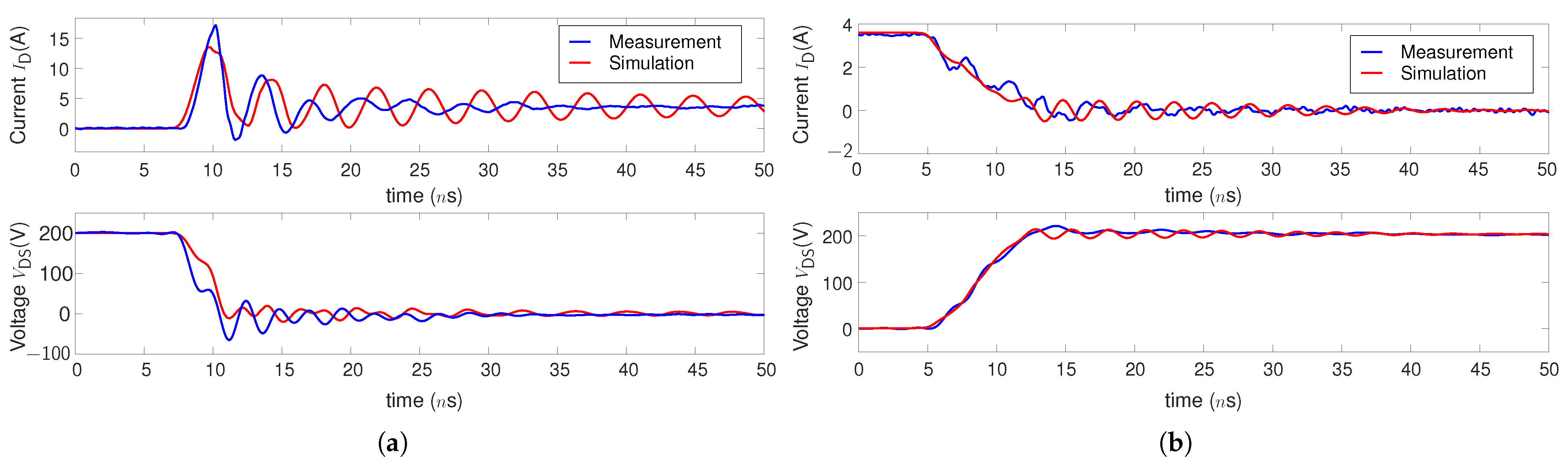
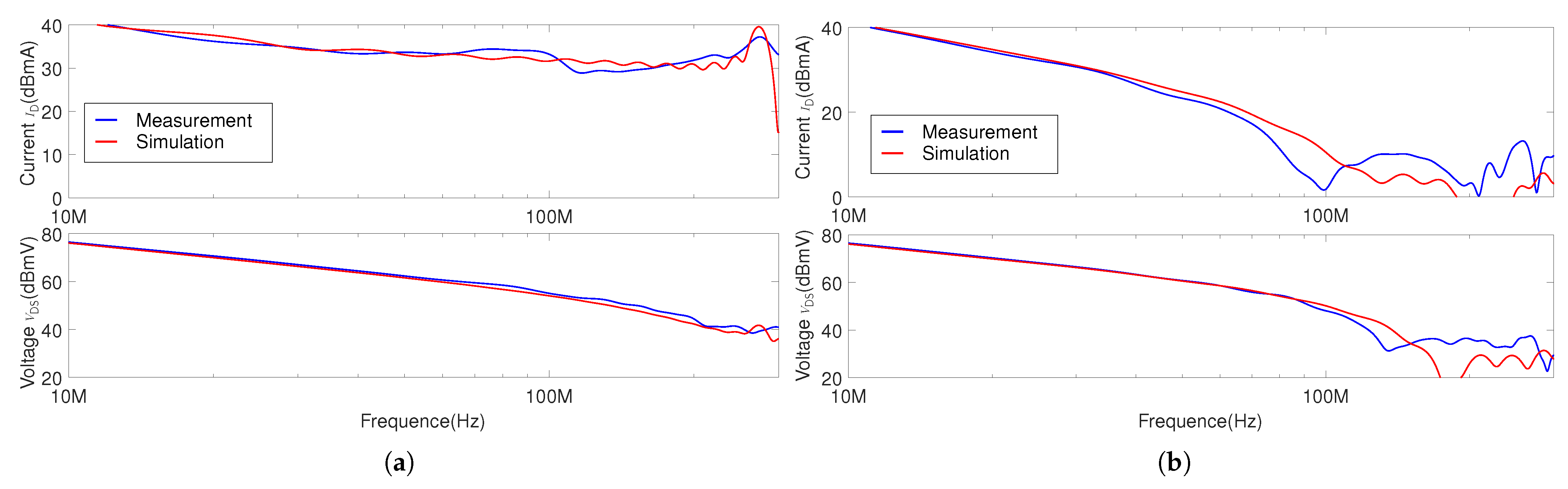
3.3. Model Validation

3.3.1. Transient and Steady State

By using the circuit presented in Figure 9a, the GaN-HEMT dynamic R DSon value at transient and steady state is at first measured under the following condition: V DC = 200 V, I L = 1.3 A, T1 remains OFF-state (T2 remains ON-state) and DUT switching frequency f sw = 100 kHz with D = 50%. Therefore, DUT is operated under soft switching and reverse conduction. Its operation time can be precisely controlled by the numbers of switching cycles. As shown in Figure 12, dynamic R DSon value decreases during ON-state. Therefore, we use R DSon B to represent its average dynamic R DSon value at the beginning of each ON-state cycle (within 100 ns) and R DSon E to represent its average dynamic R DSon value at the end of each ON-state cycle (also within 100 ns). The comparison between the model and the measurement for dynamic R DSon value at transient and steady-state is presented in Figure 13.
In terms of measured dynamic R DSon value, it is shown that both R DSon B and R DSon E gradually increase with power converter operation time until 3 s. After 3 s, they increase rapidly until 30 s and reach steady state after 100 s. This transition conforms to the τ off i observed in Figure 10a, where there is a rapid increase of dynamic R DSon value when t off is between 1 s to 30 s. The model represents good agreement to measured dynamic R DSon values at both transient and steady state. This result also suggests that reported device dynamic R DSon characterisation methods by double-pulse test or multiple pulse test in literature may not reveal device dynamic R DSon value at steady state in power converter.
In terms of dynamic R DSon value at steady state (see Figure 13b), the model shows similar trajectory as the measurement for the decrease of R DSon B towards R DSon E , where the term Δ R = R DSon B R DSon E obtained in the model is almost the same as measurement. This transition conforms to the τ on i observed in Figure 10b, where the dynamic R DSon value decreases with t on until 10 μ s.
The difference between the model and the measurement is within 10%, which validates the accuracy of the model at one operation condition. Differences between the actual, changing junction temperature and the constant value assumed in the model is one reason for this. Future work to include temperature dependency will be discussed in Section 3.3.3.

3.3.2. Different Operation Conditions

Power converter switching frequency and duty cycles are then varied to validate the model at different operation conditions. In order to increase power converter switching frequency towards megahertz, the switching losses of all four GaN transistors in the measurement circuit need to be reduced. For this reason, an LC load is used and a phase shift between two legs is added ( D DUT + D T 1 = 1 ) to control the load current I L in trapezoidal current mode (TZCM). The advantages of TZCM are that (1) all four GaN-HEMTs can be operated under ZVS soft switching to reduce switching losses and (2) the dynamic R DSon value can be measured under constant current amplitude. Measurement error due to parasitic inductance and probe deskew on measurement results can be eliminated [28].
At steady state, measurement waveforms by proposed TZCM when device switches at 1 MHz is presented in Figure 14. By setting an appropriate phase shift value, I L is in the trapezoidal form. Figure 14a represents the condition that DUT control signal delays that of T2; therefore, device R DSon B = V DSon I D is obtained when it is under constant reverse current conduction (using red curves in Figure 14a). In comparison, Figure 14b represents the condition that T2 control signal delays that of DUT; therefore, device R DSon E = V DSon I D is obtained when it is under constant forward current conduction (using red curves in Figure 14b).
The comparison between the measurement and the model for steady-state dynamic R DSon under different operation conditions is presented in Figure 15. When the device switches at 100 kHz, the model is compared with the measurement for different duty cycles. As shown in the results (see Figure 15a), the model matches well with the measurement results. Both R DSon B and R DSon E decrease with duty cycle, because effective device bias time decreases when duty cycle increases. When the duty cycle is 50%, the model is compared with the measurement for different switching frequencies (see Figure 15b), where again the model shows good agreement. The difference between R DSon B and R DSon E decreases with the increase of f sw , which suggests that device dynamic R DSon finally converges in megahertz switching power converter. As the difference between the model and the measurement is still within 10% in the above results, it can be concluded that the accuracy of the model can be validated under different operation conditions.

3.3.3. Discussion

When comparing the model with the measurement for dynamic R DSon values at steady state, it can be noted that model predicts a value smaller than the measurement. Temperature is one factor that may cause this mismatch.
In the model, R i is obtained at room temperature. When the device is operated continuously in power converter by soft switching, the junction temperature increase Δ T j is mainly caused by device conduction losses, and it is estimated to be Δ T j = I L 2 · R DSon · D · R th , j c . A heat sink is placed at the top side of the device in experiment, so junction-top thermal resistance ( R th , j t = 28 C/W) is used to estimate T j , which is around 13 C above ambient when D = 0.8. For future work, R i of different temperature can be obtained by the proposed modelling method to include temperature dependency.
In the paper, R i , τ off i and τ on i are all obtained when bias voltage V DS is 200 V. For future work, the dependency of those parameters with different bias voltage can be also included in the model by the same modelling method.

4. Conclusions

A GaN-HEMT compact model including dynamic R DSon effect is proposed in the paper, with the objective to finely model GaN-HEMT switching transients and power losses. Device static characteristics and capacitance-voltage characteristics are accurately represented by mathematical equations. The model is then implemented into our developed Power Electronics Virtual Prototyping (PEVP) software, where the parasitic inductance of the power loop and gate driver loop is accurately extracted by PEEC method. A model order reduction technique is also used in PEVP software to reduce the numbers of equations, so as to obtain the above parasitic inductance within 1 min. By comparing with experimental measurement, the model represents well turn-ON and turn-OFF switching waveforms in both time and frequency domain.
For dynamic R DSon modelling, a measurement circuit is at first proposed to extract device dynamic R DSon values as well as multiple time constants for trapping and detrapping effect. Those parameters are then represented by multiple units of RC circuit and form a behavioural voltage source in the compact model. By comparing with the experimental measurement, the model is validated to accurately represent device dynamic R DSon values at transient and steady state under different switching frequencies and duty cycles.
For future work, in order to further expand operation conditions of the model, the dependency on junction temperature and different bias voltage can be included by the same modelling method.

Author Contributions

All authors contribute equally to this work. Conceptualization, K.L., P.L.E., C.M.J., A.V. and N.I.; methodology, K.L., P.L.E. and A.V.; software, K.L., P.L.E.; validation, K.L., P.L.E., C.M.J., A.V. and N.I.; formal analysis, K.L., P.L.E., C.M.J., A.V. and N.I.; writing—original draft preparation, K.L.; writing—review and editing, P.L.E., C.M.J., A.V. and N.I.; project administration, K.L., P.L.E., C.M.J. and N.I.; funding acquisition, P.L.E., C.M.J. and N.I. All authors have read and agreed to the published version of the manuscript.

Funding

This research was funded by the UK Engineering and Physical Sciences Research Council (EPSRC) through research grant [EP/K035304/1 and EP/R004390/1] and French State Region Plan Contract Intelligent Integrated Energy Converter (CPER-CE2I) project.

Acknowledgments

We would like to acknowledge Loris Pace for technical discussions and experimental support.

Conflicts of Interest

The authors declare no conflict of interest.

Abbreviations

The following abbreviations are used in this manuscript:
GaNGallium Nitride
HEMTHigh Electron Mobility Transistors
SiCSilicon Carbide
PFCPower Factor Correction
FEMFinite Element Method
PEECPartial Element Equivalent Circuit
EMElectromagnetic
MORModel Order Reduction
PEVPPower Electronics Virtual Prototyping
ZVSZero Voltage Soft Switching
DUTDevice Under Test
PCBPrinted Circuit Board
DCMGaN-HEMT Dynamic R DSon Compact Model
SCMStandard GaN-HEMT Compact Model

References

  1. Fu, M.; Fei, C.; Yang, Y.; Li, Q.; Lee, F.C. A GaN-Based DC–DC Module for Railway Applications: Design Consideration and High-Frequency Digital Control. IEEE Trans. Ind. Electron. 2020, 67, 1638–1647. [Google Scholar] [CrossRef]
  2. Shin, J.; Ishigaki, M.; Dede, E.M.; Lee, J.S. MagCap DC–DC Converter Utilizing GaN Devices: Design Consideration and Quasi-Resonant Operation. IEEE Trans. Power Electron. 2019, 34, 2441–2453. [Google Scholar] [CrossRef]
  3. Li, X.; Ma, H.; Yi, J.; Lu, S.; Xu, J. A Comparative Study of GaN HEMT and Si MOSFET-Based Active Clamp Forward Converters. Energies 2020, 13, 4160. [Google Scholar] [CrossRef]
  4. Ma, C.T.; Gu, Z.H. Review of GaN HEMT Applications in Power Converters over 500 W. Electronics 2019, 8, 1401. [Google Scholar] [CrossRef] [Green Version]
  5. Li, K.; Evans, P.; Johnson, M. SiC/GaN power semiconductor devices: A theoretical comparison and experimental evaluation under different switching conditions. IET Electr. Syst. Transp. 2018, 8, 3–11. [Google Scholar] [CrossRef] [Green Version]
  6. Li, K.; Evans, P.; Johnson, M. Developing Power Semiconductor Device Model for Virtual Prototyping of Power Electronics Systems. In Proceedings of the 2016 IEEE Vehicle Power and Propulsion Conference (VPPC), Hangzhou, China, 17–20 October 2016; pp. 1–6. [Google Scholar] [CrossRef]
  7. Liu, Z.; Huang, X.; Lee, F.; Li, Q. Package Parasitic Inductance Extraction and Simulation Model Development for the High-Voltage Cascode GaN HEMT. Power Electron. IEEE Trans. 2014, 29, 1977–1985. [Google Scholar] [CrossRef]
  8. Endruschat, A.; Novak, C.; Gerstner, H.; Heckel, T.; Joffe, C.; März, M. A Universal SPICE Field-Effect Transistor Model Applied on SiC and GaN Transistors. IEEE Trans. Power Electron. 2019, 34, 9131–9145. [Google Scholar] [CrossRef]
  9. Liang, M.; Zheng, T.Q.; Li, Y. An Improved Analytical Model for Predicting the Switching Performance of SiC MOSFETs. J. Power Electron. 2016, 16, 374–387. [Google Scholar] [CrossRef] [Green Version]
  10. Pace, L.; Chevalier, F.; Videt, A.; Defrance, N.; Idir, N.; De Jaeger, J.C. Electrothermal Modeling of GaN Power Transistor for High Frequency Power Converter Design. In Proceedings of the 2020 22nd European Conference on Power Electronics and Applications (EPE’20 ECCE Europe), Virtual, Lyon, France, 7–11 September 2020; pp. 1–10. [Google Scholar] [CrossRef]
  11. Cai, Y.; Forsyth, A.J.; Todd, R. Impact of GaN HEMT dynamic on-state resistance on converter performance. In Proceedings of the 2017 IEEE Applied Power Electronics Conference and Exposition (APEC), Tampa, FL, USA, 26–30 March 2017; pp. 1689–1694. [Google Scholar] [CrossRef]
  12. Foulkes, T.; Modeer, T.; Pilawa-Podgurski, R.C.N. Developing a standardized method for measuring and quantifying dynamic on-state resistance via a survey of low voltage GaN HEMTs. In Proceedings of the 2018 IEEE Applied Power Electronics Conference and Exposition (APEC), San Antonio, TX, USA, 4–8 March 2018; pp. 2717–2724. [Google Scholar] [CrossRef]
  13. Badawi, N.; Hilt, O.; Bahat-Treidel, E.; Böcker, J.; Würfl, J.; Dieckerhoff, S. Investigation of the Dynamic On-State Resistance of 600 V Normally-Off and Normally-On GaN HEMTs. IEEE Trans. Ind. Appl. 2016, 52, 4955–4964. [Google Scholar] [CrossRef]
  14. Yang, F.; Xu, C.; Akin, B. Quantitative Analysis of Different Operating Conditions’ Effect on Dynamic On-Resistance in Enhancement-Mode GaN HEMTs. In Proceedings of the 2018 IEEE 6th Workshop on Wide Bandgap Power Devices and Applications (WiPDA), Atlanta, GA, USA, 31 October–2 November 2018; pp. 134–140. [Google Scholar] [CrossRef]
  15. Galapon, B.J.; Hanson, A.J.; Perreault, D.J. Measuring Dynamic On Resistance in GaN Transistors at MHz Frequencies. In Proceedings of the 2018 IEEE 19th Workshop on Control and Modeling for Power Electronics (COMPEL), Padua, Italy, 25–28 June 2018; pp. 1–8. [Google Scholar] [CrossRef]
  16. Lu, B.; Palacios, T.; Risbud, D.; Bahl, S.; Anderson, D. Extraction of Dynamic On-Resistance in GaN Transistors: Under Soft- and Hard-Switching Conditions. In Proceedings of the Compound Semiconductor Integrated Circuit Symposium (CSICS), Waikoloa, HI, USA, 16–19 October 2011; pp. 1–4. [Google Scholar] [CrossRef]
  17. Li, R.; Wu, X.; Yang, S.; Sheng, K. Dynamic on-State Resistance Test and Evaluation of GaN Power Devices Under Hard- and Soft-Switching Conditions by Double and Multiple Pulses. IEEE Trans. Power Electron. 2019, 34, 1044–1053. [Google Scholar] [CrossRef]
  18. Uren, M.J.; Karboyan, S.; Chatterjee, I.; Pooth, A.; Moens, P.; Banerjee, A.; Kuball, M. “Leaky Dielectric” Model for the Suppression of Dynamic Ron in Carbon-Doped AlGaN/GaN HEMTs. IEEE Trans. Electron. Devices 2017, 64, 2826–2834. [Google Scholar] [CrossRef] [Green Version]
  19. Li, K.; Videt, A.; Idir, N.; Evans, P.; Johnson, M. Modelling GaN-HEMT Dynamic ON-state Resistance in High Frequency Power Converter. In Proceedings of the 2020 IEEE Applied Power Electronics Conference and Exposition (APEC), New Orleans, LA, USA, 15–19 March 2020; pp. 1949–1955. [Google Scholar] [CrossRef]
  20. GaNSystems GS66502B Datasheet REV180420. Available online: https://gansystems.com/wp-content/uploads/2018/04/GS66502B-DS-Rev-180420.pdf (accessed on 5 June 2018).
  21. Pace, L.; Defrance, N.; Videt, A.; Idir, N.; Dejaeger, J. S-Parameter Characterization of GaN HEMT Power Transistors for High Frequency Modeling. In Proceedings of the PCIM Europe 2018, International Exhibition and Conference for Power Electronics, Intelligent Motion, Renewable Energy and Energy Management, Nuremberg, Germany, 5–7 June 2018; pp. 1–8. [Google Scholar]
  22. Yeo, H.L.; Tseng, K.J. Modelling technique utilizing modified sigmoid functions for describing power transistor device capacitances applied on GaN HEMT and silicon MOSFET. In Proceedings of the 2016 IEEE Applied Power Electronics Conference and Exposition (APEC), Long Beach, CA, USA, 20–24 March 2016; pp. 3107–3114. [Google Scholar] [CrossRef]
  23. Jardel, O.; Callet, G.; Charbonniaud, C.; Jacquet, J.C.; Sarazin, N.; Morvan, E.; Aubry, R.; Di Forte Poisson, M.; Teyssier, J.; Piotrowicz, S.; et al. A new nonlinear HEMT model for AlGaN/GaN switch applications. In Proceedings of the 2009 European Microwave Integrated Circuits Conference (EuMIC), Rome, Italy, 28–29 September 2009; pp. 73–76. [Google Scholar]
  24. Evans, P.; Castellazzi, A.; Johnson, C. Design Tools for Rapid Multidomain Virtual Prototyping of Power Electronic Systems. Power Electron. IEEE Trans. 2016, 31, 2443–2455. [Google Scholar] [CrossRef]
  25. Li, K.; Evans, P.; Johnson, M. Using multi time-scale electro-thermal simulation approach to evaluate SiC-MOSFET power converter in virtual prototyping design tool. In Proceedings of the 2017 IEEE 18th Workshop on Control and Modeling for Power Electronics (COMPEL), Stanford, CA, USA, 9–12 July 2017; pp. 1–8. [Google Scholar]
  26. Zulauf, G.; Guacci, M.; Rivas-Davila, J.M.; Kolar, J.W. The Impact of Multi-MHz Switching Frequencies on Dynamic On-Resistance in GaN-on-Si HEMTs. IEEE Open J. Power Electron. 2020, 1, 210–215. [Google Scholar] [CrossRef]
  27. Yang, S.; Han, S.; Sheng, K.; Chen, K.J. Dynamic On-Resistance in GaN Power Devices: Mechanisms, Characterizations and Modeling. IEEE J. Emerg. Sel. Top. Power Electron. 2019. [Google Scholar] [CrossRef]
  28. Li, K.; Videt, A.; Idir, N.; Evans, P.L.; Johnson, C.M. Accurate Measurement of Dynamic on-State Resistances of GaN Devices Under Reverse and Forward Conduction in High Frequency Power Converter. IEEE Trans. Power Electron. 2020, 35, 9650–9660. [Google Scholar] [CrossRef]
Figure 1. GaN-HEMT compact model by equivalent circuit.
Energies 14 02092 g001
Figure 2. Comparison between model and datasheet for device I D - V DS characteristics.
Energies 14 02092 g002
Figure 3. Comparison between the model and datasheet or experiment for device interelectrode capacitance values: (a) C iss , C oss and C rss values. (b) C gs - V GS value.
Energies 14 02092 g003
Figure 4. Simulation technique used in PEVP software.
Energies 14 02092 g004
Figure 5. GaN-HEMT half-bridge circuit prototype and its models in PEVP: (a) Prototype. (b) Models in PEVP. (c) Obtained L para for power loop and gate loop.
Energies 14 02092 g005
Figure 6. Comparison between simulation and measurement for 200 V/4 A switching transients: (a) Turn-ON. (b) Turn-OFF.
Energies 14 02092 g006
Figure 7. Spectrum comparison between simulation and measurement for I D and V DS magnitude at 200 V/4 A: (a) Turn-ON. (b) Turn-OFF.
Energies 14 02092 g007
Figure 8. V DS bias effect on GaN-HEMT dynamic R DSon .
Energies 14 02092 g008
Figure 9. Measurement circuit and control signal: (a) Electrical circuit. (b) Control signals and load current.
Energies 14 02092 g009
Figure 10. Comparison between analytical model and measurement on GaN device dynamic R DSon value under single pulse measurement: (a) Under different t off . (b) Under different t off and t on .
Energies 14 02092 g010
Figure 11. GaN-HEMT dynamic R DSon compact model.
Energies 14 02092 g011
Figure 12. Comparison between GaN-HEMT SCM and DCM for dynamic R DSon value.
Energies 14 02092 g012
Figure 13. Comparison between model and measurement for GaN device dynamic R DSon value when device is switched at 100 kHz, D = 50%: (a) Transient and steady state. (b) At one switching cycle in steady state.
Energies 14 02092 g013
Figure 14. GaN-HEMT dynamic R DSon measurement results by proposed TZCM when device switches at 1 MHz: (a) R DSon B and (b) R DSon E .
Energies 14 02092 g014
Figure 15. GaN-HEMT dynamic R DSon value of different operation conditions: (a) different duty cycles ( f sw = 100 kHz) and (b) different switching frequencies (D = 50%).
Energies 14 02092 g015
Table 1. Parameters used in Equation (1).
ab1b2cdef1f2
1.18371310.51.70.310.2554.16.1
Table 2. Parameters used in Equation (2).
n a n b n c n d n e n f n g n h n i n j n
1131.4 · 10 12 42.71 · 10 12 −1.732−1.313690 · 10 12 0.2736−2.689668 · 10 12 0.2712−2.598
2100 · 10 12 60.85 · 10 12 1.4051.514.93 · 10 12 0.916953.933 · 10 12 0.07737−35
3103.5 · 10 12 9.43 · 10 12 0.03019−118.911.49 · 10 12 0.7−47.3420 · 10 12 0.06603−51.22
Table 3. Comparison between PEVP and ADS for parasitic inductance value simulation.
Simulation Software L gate L power Simulation Time
PEVP9.7 nH5.4 nH∼0.7 min
ADS9.6 nH5.7 nH∼100 min
Table 4. Comparison between simulation and measurement for switching energy.
E sw , ON E sw , OFF E sw , tot
Simulation3 μ J0.9 μ J3.9 μ J
Measurement2.1 μ J0.7 μ J2.8 μ J
Table 5. Different parameters used in the model.
i τ off i (s) τ on i (s) R i ( Ω )
1 10 6 5 × 10 7 0.255
20.002 9.9 × 10 6 0.21
3 5 × 10 5 0.020.2185
40.19820.2162
56.81000.26
Publisher’s Note: MDPI stays neutral with regard to jurisdictional claims in published maps and institutional affiliations.

