1. Introduction
The energy supplied to electric machines and drive systems constitutes a significant part of industrial electrical power consumption. During the operation of a motor, some of the delivered energy is converted into losses responsible for the heating of motor elements. Excessive heating of motor parts leads to damage to the machine; and therefore, thermal losses must be effectively minimized. Losses in smaller motors are also of relatively lower value, but the motors are still subject to thermal issues. Therefore, close attention needs to be paid to the thermal analysis of motor operation, which can result in significant improvements in motor performance.
The increased awareness of the significance of thermal issues in electric motors has led to the development of numerous electric motor thermal models. The methods used to estimate rotor bar temperatures for line-connected induction can be categorized into two classes: thermal-model-based ones and parameter-based ones. The thermal-model-based methods simulate the thermal behaviors of the motor to estimate the rotor bar temperature, but the thermal parameters are calculated from motor dimensions [
1] or off-line experiments [
2,
3]. Despite the robustness of these methods, thermal parameters are inconstant and need to be calculated under various operation conditions. Although the on-line methods are accurate and can take into account alterations of cooling conditions, they are still too sensitive to modifications of unknown machine parameters. These methods have been successfully implemented to estimate the rotor temperature for line-connected motors during standard conditions. It is much more difficult to estimate the temperature during abnormal operation because of the skin effect, which impacts rotor resistance making it slip dependent. However, the application of the algorithm to include the influence of slip dependency in these methods has been suggested [
4]. The understanding of the thermal effect’s impact during varying conditions is very important for the proper design of a given motor. The basics of a motor thermal model and description of its applications in protection relays are discussed in [
5].
This paper provides mathematical interpretation of a motor thermal model for different stages of operation. This article also focuses on the explanation of thermal model time constants and other technical parameters that result in the biasing of the thermal model algorithm. Thermal interactions in an asynchronous motor can be tested by measuring the rotor temperature using a slip ring assembly in a laboratory test rig [
6]. This paper presents the detailed description of steady-state and transient temperature changes in the stator and the rotor of an induction motor. The accurate estimation of a thermal resistance is crucial for increasing the accuracy of analytical thermal models. It is worth emphasizing the fact that the accuracy also increases with the number of nodes in the used equivalent thermal circuit of a motor. The accurate mathematical model used for predicting the dynamic reaction in response to a control input is also presented in [
6]. The safe stall time of the machine both for motor acceleration and stall states is the main objective of evaluation of the motor maximum allowable temperature because of the difficulties with taking direct measurements of the rotor’s temperature. The next aspect to be considered is stator insulation degradation, that is, the chemical process, which accelerates as the temperature rises and can be described by the Arrhenius equation. Thermal and electromagnetic analysis can be performed with programs using the finite element method (FEM). The accuracy of the no-load losses calculation in an induction motor using the FEM model is based on three approaches: without hysteresis, skin effect influence, and with successive addition of the phenomena. All these approaches are discussed in [
7]. FEM can calculate the distribution of the temperature and transfer of heat in a motor for steady and transient states, and such an analysis performed in ANSYS is shown in [
8]. As described in [
9], stator design, rotor design, and frame design can influence the amplitude of starting currents.
In this paper, the thermal behavior of a three-phase asynchronous machine is also analyzed. The temperature of the machine is estimated using the thermal-model-based estimator. The thermal characteristics of a motor are modeled using the lumped-parameter thermal circuit. Stator design, rotor design, and frame design can influence the starting currents. Thus, in the course of the design phase, the thermal and mechanical constraints of the construction also have to be considered. The thermal capacitance and resistance can be estimated using a small group of factors such as full load current (FLC), service factor (SF), and trip class [
9] when considering only motors having equal parameters. Therefore, parameters used in lumped-parameter thermal circuits can be calculated from (a) dimensional data and (b) test data. Even simple lumped-parameter models that include only one source of heat and one energy storage can provide quite accurate rotor temperature estimation. First-order thermal models are commonly used in the thermal protection solutions of relays [
10] because of their simplicity. Therefore, in [
10] the method used for the calculation of the temperature increase in asynchronous machines is discussed and adopted in a digital relay. The ways in which the algorithms detect overload, failure of starting, unbalance, and successive starting are also described.
The complex thermal models of electric motors usually provide more accurate results. Faster results of temperature estimation can be achieved by reducing the number of nodes in the equivalent thermal circuit [
11]. Researchers analyzing thermal phenomena in motors during transient and steady-state operation have typically used thermistors, infrared cameras, temperature-sensitive paint, temperature-sensitive stickons, heat-flow sensors, and other devices to get experimental data. It is convenient to use this kind of the equipment when the rotor is at standstill. Therefore, the main aim is to achieve accurate and reliable estimations of rotor temperature. However, such temperature estimations should be done avoiding the use of thermal sensors, wiring, and other equipment connecting them to a motor control center. Avoiding additional related costs is also of key importance in the rotor temperature estimations [
12]. In [
13], the thermal limit curves are utilized together with supporting motor data to establish thermal protection using the thermal model of an induction motor. In [
14], the thermal model is represented by the time-discrete form of the differential equation describing temperature rise as the result of Joule heating and fundamental principles. In this paper, the method of modification of the thermal model applied in overload protection relays made by different manufacturers is proposed. This method provides good results for different motors under waveform distortion. In the revised model, thermal constraints of the rotor and stator are assessed simultaneously to evaluate the permissible temperature range. Machine designers frequently utilize full-order thermal models to examine the performance of an asynchronous motor [
15]. However, the full-order thermal models can be methodically simplified through pole-zero cancelation or using Hankel singular-values-based model reduction methods. Thus, second-order or first-order thermal models may be effective enough to resolve the problem of rotor temperature evaluation. At the same time, a sensorless rotor temperature estimator can also be used for asynchronous motors [
16]. The estimator only needs measurements of current and voltage for the on-line evaluation of rotor temperature. Then, the inductances of the motor are calculated using an equivalent circuit of the machine based on the orientation of the rotor flux field. These parameters then become the input of the algorithm estimating rotor resistance. The rotor temperature is related with its resistance by a linear relationship that provides the final result. Reference [
17] examines the additional possible methods to estimate the machine temperature. Second-order or higher-order thermal-model-based methods can also be effectively used for this purpose. In the discussed approaches, different parts of the machine are modeled separately resulting in more accurate representation of dynamic thermal behavior. The calculation of the model parameters is based on the machine dimensions or the results of off-line experiments. However, the thermal parameters of the motor are not constant and need to be recalculated under separate working conditions to provide a more precise output. Reference [
18] describes the development and testing of the simple and reliable third-order thermal model appropriate for the thermal protection of self-ventilated asynchronous machines operating on variable-load, variable-speed duty cycles.
One of IEEE studies estimates that motor failures caused by persistent overload constitute 4.2% of all motor failures [
5]. One way of reducing this problem is to set a longer reset delay. Unfortunately, maximum setting of the parameter (typically 60 s) is the limitation of this method. However, thermal overload relays make use of thermal memory, which constantly measures the load and evaluates temperature. This leads to the situation where machine circuits can work near to their thermal limits leading to the increased exploitation of the power system. The problem can be partially overcome by using the thermal overload protection functions embedded into modern IED (intelligent electronic device) relays that constantly check the thermal load in real time. These functions (ANSI 49) use very advanced algorithms that map the thermal picture of the protected device accurately. These algorithms should be set and coordinated correctly to prevent mis-operations and equipment damage, to ensure proper operation of the functions. Unfortunately, the algorithms using operate time curves for their functions are usually neglected in relay coordination programs as a consequence of their mathematical complexity.
This article presents the laboratory standard for measuring the temperature of individual motor components. The exact results of laboratory tests with intermittent motor operation are also shown. On the basis of these test results, it is demonstrated that the time constant of the individual motor elements depends on the temperature. At the same time, it is proved that the specific heat is a function of temperature. The performed analysis has highlighted the fact that the first-order motor thermal models do not map the thermal processes occurring in motors precisely, especially in the case of intermittent operation.
Motor protection is needed to reduce the effects caused by abnormal operating states of motors fitted with protection from:
interphase short circuits,
earth fault,
overload,
voltage drop,
improper start-up,
falling out of synchronism, or
asymmetry of voltage.
Protection for low-voltage motors is much simpler, yet less expensive, due to the relatively low price of the motor. In the case of low-voltage motors, although a contactor circuit is present, it is used as a short-circuit protection device. In addition, protection is applied to motor overloads. Low-voltage motors, switched by contactors, do not require undervoltage protection. The contactor electromagnet causes an immediate opening when the voltage drops below 50% of the rated voltage.
In the case of low-voltage motors, several types of protection devices are used:
sensors (temperature-responsive),
protectors (responding to the current value in the winding and temperature),
thermal overload triggers, or
thermal overcurrent relays.
Protection from the effects of long-term overloads should be performed using a thermal relay. In the case of long-term overload, there is a danger of overloading the motor rotor and stator. Accurate information regarding the thermal processes occurring in the motor is virtually impossible to obtain. The precise nature of these processes can be known only by conducting appropriate tests.
3. Motor Thermal Model
In this paper, it was decided to present the essence of the phenomenon of thermal processes in the engine in the simplest possible way. Therefore, physical model tests and the empirical approach were used for comparison.
Considering the simplest case of heating up the motor stator windings, they can be treated as a homogeneous body of thermal power, which is also equal to the power losses in the stator windings [
19]. The determination of the heat balance equation of this system is done as follows:
where
Ru—stator winding resistance (Ω),
I—current through the stator windings (A),
m—mass of the winding (kg),
c—specific heat of the stator windings (J/kg/K),
ϑ—temperature (K),
t—time (s),
kp—coefficient of heat transfer from the windings to the ambient (W/K/m2), and
S—surface area through which heat is released (m2).
Equation (1) can be transformed into the form:
where
T—the thermal time constant of the motor, ranging from several to tens of minutes (s), and
ϑu—temperature at which to determine the winding current flow during long-term value of I (K).
Taking into account the initial condition
ϑ =
ϑp (for
t = 0), we can solve Equation (2) in order to obtain the relationship that specifies the change in temperature of the winding as a function of time:
When the winding temperature, ϑg, is exceeded, a thermal relay will boost the motor off from work. In practical solutions, the thermal relay is often realized as a temperature alarm, ϑalarm.
As calculated from Equation (3), if the temperature threshold, ϑ, is higher than the set temperature, ϑalarm, an alarm is sent as a warning to the appropriate personnel. The temperature alarm is set above the observed temperature during motor operation at rated conditions and lower than the given temperature limit thatcould contribute to damage ofthe motor stator windings.
From Equation (3), one can determine the time for the coil temperature to reach the limit
ϑg. This time dependence can be determined as follows:
where
Ip—the pre-load current (A), also ϑp=RuIp2/(kpS), and
Ig—current limit, which causes the flow to determine the winding temperature equal to ϑg (A), also ϑg=RuIg2/(kpS).
The current limit,
Ig, is defined as multiples of
k usually rated motor current
In. The time characteristics can be determined according to the IEC 255-8 standards adopted in the equation:
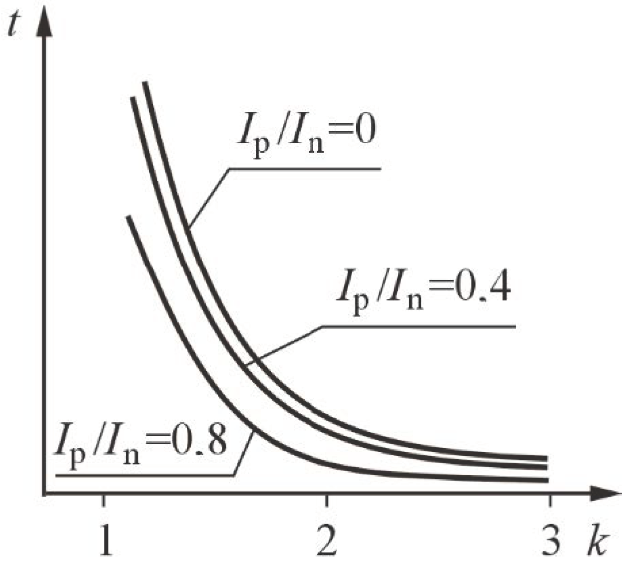
If the task on hand is to protect the thermal relay motor from overloading, its thermal model should correspond as closely as possible to the protected element. To faithfully reproduce the temperature change, its time–current characteristic should be determined by Equation (4). Equation (5) is the basis of the temperature measurement algorithm (motor warm-up process) used in the thermal design of many digital relays. The characteristics of such a relay areshown in
Figure 2. Even the simplest thermal relays are conducted in accordance with Equation (5). In these embodiments, it is assumed that
R =
Ru, so that the capacitance,
C, can be determined as
C =
T/
Ru. The voltage drop in the capacity of
UC is then directly proportional to the stator winding temperature,
ϑ.
Generally, the thermal tests of one heating and cooling cycle of the motors are known. This paper focuses mainly on the results of tests obtained with an intermittent motor duty cycle. The time constant is the basic parameter characterizing every thermal object. It is not a constant quantity, but a function of the specific heat of a given material. The following formula describes the relationship between the time constant and the material’s specific heat.
where
G—weight (kg),
c—specific heat (J/kg/K),
S—active cooling surface (m2), and
h—body surface heat release rate (W/kg/m2).
Based on the above formula, it can be concluded that the change in the time constant is dependent on the changes in specific heat and the body surface heat release rate associated with the cooling conditions of the machine (when cooling, this parameter decreases).
From the physical point of view, the motor is not a homogeneous body. For the thermal analysis of various materials, it is useful to know the Debye temperature—
ϑD. Each solid has a characteristic Debye temperature, below which a significant deviation of molar heat dependence (heat capacity of one mole of substance) from the Dulong–Petit law is observed, which says that, for most metals, the molar specific heat in normal conditions is 25.1 (J/(mol·K)), [
20].
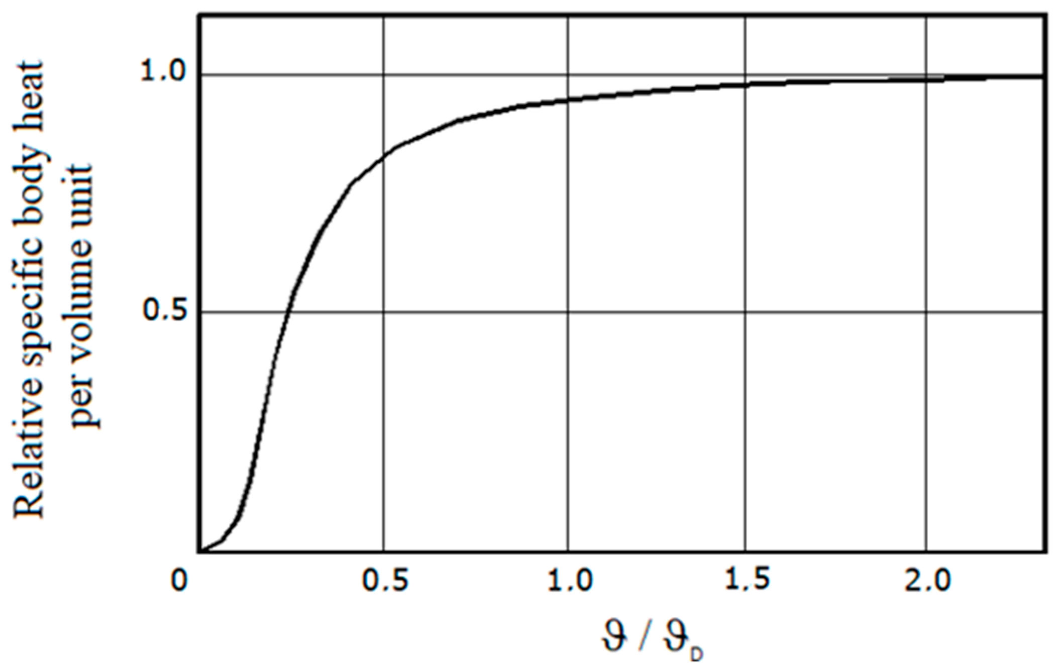
Figure 3 shows the change in the body’s specific heat per volume unit (in the Debye model) depending on the ratio of the body temperature, ϑ, to the Debye temperature,
ϑD [
21].
The Debye temperatures for the metals the motor is built withare, respectively, 343 K (70 °C) for copper and 467 K (194 °C) for iron. The difference of these values indicates the complexity of the thermal analysis of thermal process taking place in the motor. The high Debye’s temperature for iron confirms that there is a thermal dependence between the motor time constant and its current thermal state. Heating and cooling of motor elements in various operating states is taken into account during the analysis of thermal phenomena occurring in electric machines. From the point of view of overload protection, we are most interested in those parts of the motor that are exposed to the highest temperature values. It should be noted, however, that limiting the analysis to heat processes only for these elements is highly inaccurate due to the strong correlations occurring between the various parts of the motors.
3.1. First-Order Thermal Model
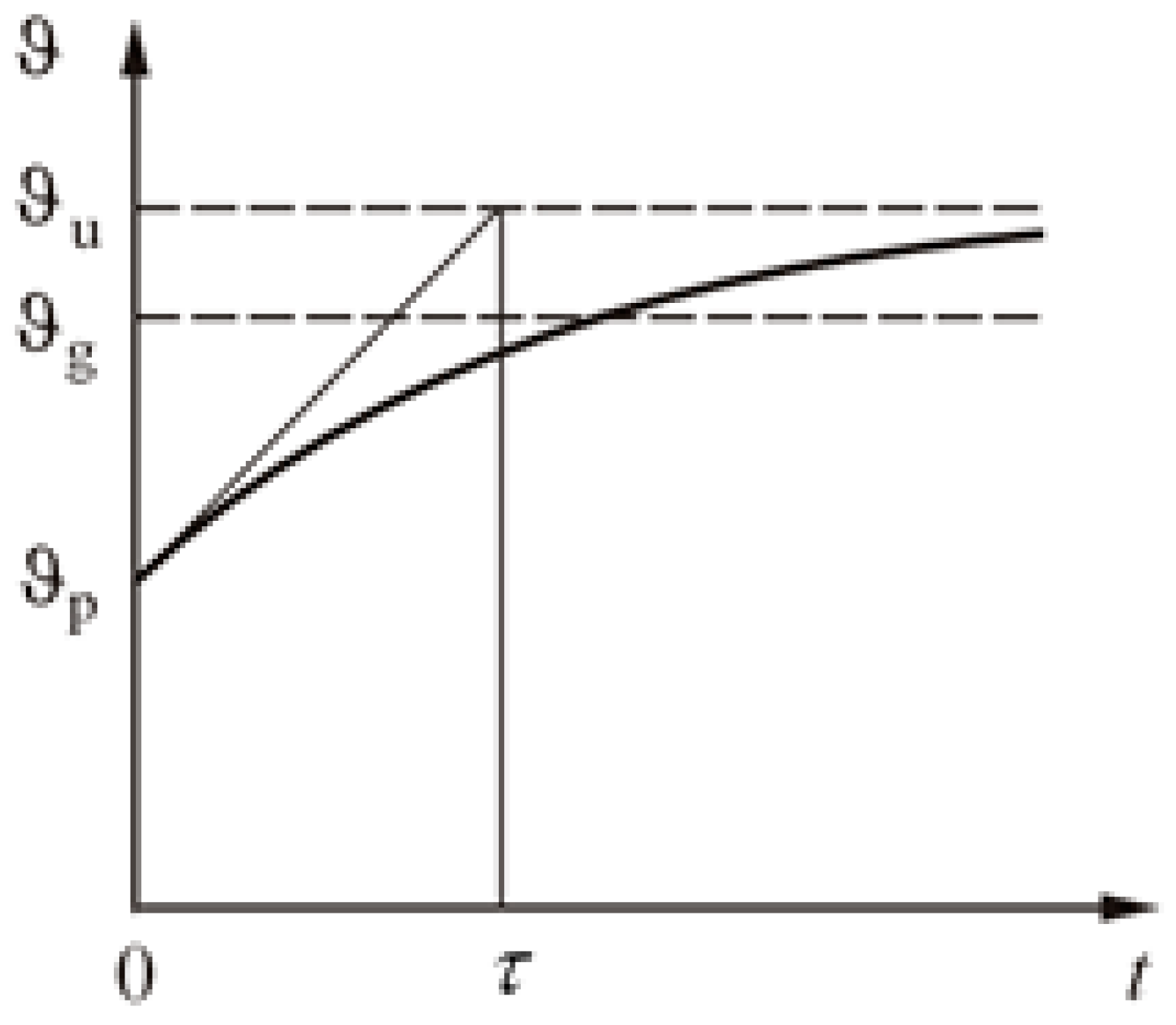
The mathematical model describing the thermal processes occurring in the motor with a single-exponential curve is determined by the following relationship:
where
ϑu—temperature of the stator winding (K),
ϑn—nominal temperature increase (K),
ϑo—ambient temperature (K),
I/In—ratio of the motor load current to its rated current, and
τ =
Ru⋅
Cu—time constant of the stator winding (s), shown in
Figure 4.
The following electrical scheme shown in
Figure 5 was proposed based on the mathematical model.
The following symbols were adopted:
J = (I/In)2—relative current square proportional to the square of the motor load current,
Cu—capacitor capacity corresponding to the thermal capacity of the motor winding (s/K), and
Ru—resistance corresponding to the resistance of heat dissipation through the winding to the environment (K).
3.2. Second-Order Thermal Model
A better form of modeling thermal waveforms consists in replacing the motor thermal structure with a system of two thermally homogeneous elements, with the first heating element havinglosses proportional to copper losses in the motor and havinga thermal capacity corresponding to the thermal capacity of the motor winding, while the second element is heated by the heat transmitted from the first element and its heat capacity corresponds to the thermal capacity of the motor’s yoke [
22].
The heat emitted in the first element is partially accumulated. The rest is given back by the thermal resistance, reflecting the intensity of motor cooling, and is transmitted to the environment. The second-order thermal model can be described by the following equation:
where
ϑu, ϑn, ϑo, I/In—the same symbols as for the first-order model,
τ1, τ2—time constants that are functions of all capacities and thermal resistances (s), and
k1—a coefficient that is a function of heat capacity and thermal resistance as well as power losses.
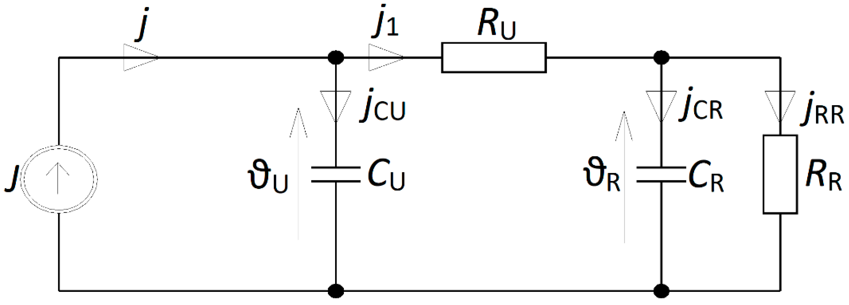
The bi-exponential model is represented by the electrical scheme in
Figure 6.
The following symbols were adopted:
J, Cu, Ru—the same symbols as for the first-order model,
CR—capacitor capacity corresponding to the thermal capacity of the motor yoke (s/K), and
RR—resistance corresponding to the heat dissipation resistance of the yoke (K).
4. Heating Tests Results and Proposed Third-Order Model
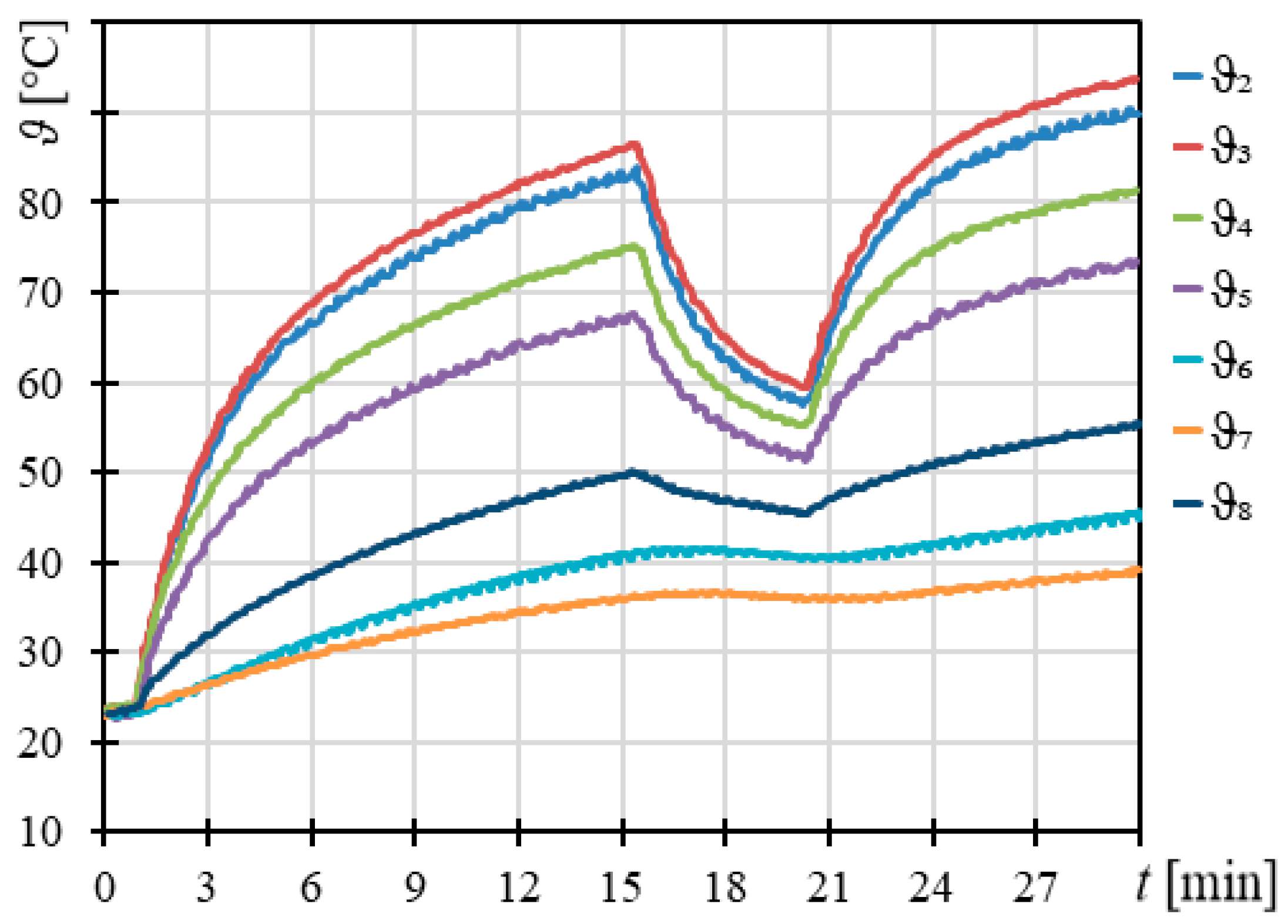
The results of the motor heating laboratory tests are shown in
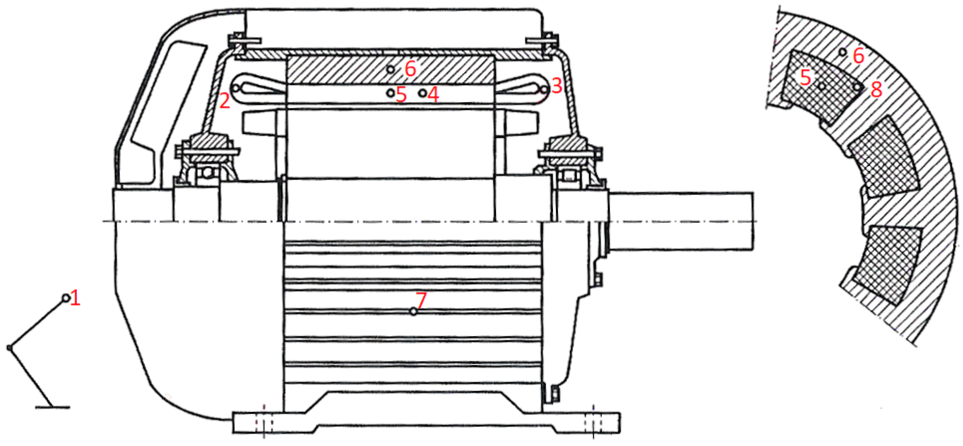
Figure 7. It is found that the description of the heating processes using one-exponential model described by Equation (7) is not very precise. Based on the data obtained in the measurementof the temperature curveat different points in the motor under test, calculations of the correlation coefficients were made. The obtained results shown that that there is a strong relationship between the following waveforms: ϑ
2, ϑ
3, ϑ
4, and ϑ
5, of which ϑ
2 (temperature of front end winding) is the highest. The temperature waveformsmeasured atthe other threepoints ofthe motor, i.e., ϑ
6, ϑ
7, and ϑ
8, are correlatedwith each otherbut havea weakerassociationwith the previouslymentionedwaveforms. Basedon the results ofstatistical calculations, one can state that better determination of temperature changes in the motor windings can be obtained by modeling the motor as a system of interconnected heat capacity. The first one would correspond to the thermal capacity of the second winding up the yoke. Moreover, the protection does not include the fact that the specific heat of all materials is temperature dependent. Thus, accurate thermal models would make the value of the thermal time constant variable with an increase in temperature and specific heat. A third-order thermal model can then be used in order toimprove the accuracy ofthe system analysis.
The introduction of a third-order thermal model was dictated by the need to increase the accuracy of mapping the dynamically variable waveforms of heat occurring in different parts of the motor. In the proposed system, the motor is modeled based on the electrical diagram shown in
Figure 8. The way how the heat waveforms are mapped is similar to the method used for the bi-exponential model, except that the motor winding is divided into two parts: winding fronts and windings placed in slots. This breakdown is due to the different thermal conditions under which the different parts of windings operate.
The following mapping of the different motor parts was adopted:
JC—current forced proportional to the amount of heat produced in the winding front part,
JZ—current forced proportional to the amount of heat produced in windings placed in the slots where JZ + JC = J = (I/In)2,
CC, RC—parameters of the winding front,
CZ, RZ—parameters of the slot windings,
CR, RR—parameters of the stator yoke, and
RCR, RZR—resistance corresponding to the reluctance of heat transfer from the motor winding to the yoke.
The following equations can be formulated for the electrical system shown in
Figure 8:
A simulation model was built in the MATLAB/Simulink-based environment on the above-presented relationships. The obtained thermal model of the motor was expanded by a correction system, thanks to which it is possible to dynamically change (map) the value of the thermal time constant of the stator yoke.
The dynamic correction system, which contains the motor thermal model proposed in the paper, serves as a controller, while the object to be controlled here is the thermal capacity of the yoke—CR. The measured value applied to the input of the regulator is the thermal state (temperature) of the stator yoke calculated by mapping the part of the motor component using the parameters (RR, CR).
The main problem that occurred in the construction of the dynamic correction system was to determine the correction function,
f(
ϑ), implementing the previously described regulator. In order to solve this problem, data from the temperature curve registered during motor thermal tests were used. Calculations are performed based on the assumption that the temperature dependency of the yoke’s thermal capacity can be determinedby multiplication of the capacity by the following factor:
The basic feature of the third-order model, clearly visible in
Figure 8, is the introduced time constant, which depends on the core temperature being, as previously described, the control quantity.
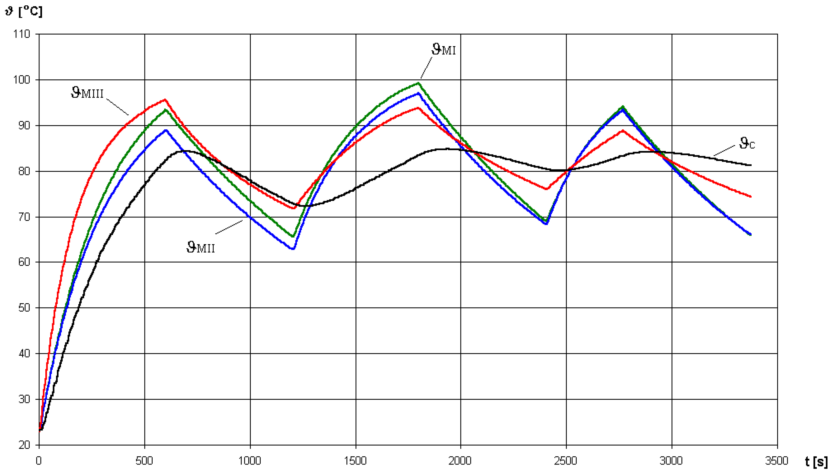
Based on the results of the simulation, it can be concluded that the first-and second-order tested models introduce low error values when the motor is heated from the cold state. If the motor is operating in the intermittent mode, the winding temperature calculated by the models is significantly different from the measured value, which is caused by the “stiff” time constant value. The basic feature of the third-order model, clearly visible in
Figure 9, is the correction of the time constant depending on the value of the core temperature being as described above with the control value. A comparison of test results for models of different orders is shown in
Figure 9. The values of model parameters were as follows:
- -
first-order model: RU = 85 K, CU = 3.53 s/K,
- -
second-order model: RU = 70 K, CU = 4.29 s/K, RR = 15 K, CR = 24 s/K,
- -
third-order model: RC = 290 K, CC = 1.03 s/K, RR = 170 K, CR = 1.85 s/K, RZ = 60 K, CR = 6 s/K, RZR = RCR = 70 K.
When the motor cools down, time constants of the models were quadrupled by multiplying the resistances by four.
The research was mainly aimed at observing the operation of thermal models in theintermittent motor regime. The reference value for which heat waveforms generated by the tested models were compared was the temperature of the front stator wingding’s overhang (in low-voltage motors this part of the winding heats up the most—it is the most vulnerable spot of the motor).
5. Conclusions
The strength of the article is not in making huge complex models, as the models may be different, but in verifying with actual measurements.
The analysis of the results, in particular, dealing with the motor’s intermittent operation, confirms that the time constantof the various elements of the machine, which is proportional to the specific heat, depends on temperature. Thus, the single-exponential protection models are not a sufficiently precise representation of the actual thermal processes.
The results for the measurement of temperatures of the selected motor elements clearly show that the thermal time constant is a function of temperature. Change (increase) in the thermal time constant is due to the change (increase) in specific heat.
The calculations of the correlation coefficients between the courses of the temperature at various points of the motor indicate that the structure of the thermal model to be expressed, should be at least secondorder, and two elements have to be mapped: the stator winding and the motor yoke.
As a result of the research and analysis of thermal models of asynchronous motor used to implement the overload relay, it can be stated that single- and bi-exponential classical models of motors do not provide an accurate mapping of the thermal state of the motor operating in the intermittent operation cycle, because they do not take into account changes in the thermal time constant as a result of temperature rise, and the only correction introduced is a “swept” change depending on themotor operation.
The digital overload relay used for protecting motors should be equipped in a function correcting the thermal time constant value depending on the thermal state of the motor.
The third-order (three exponential) thermal model proposed in this paper enables the dynamic correction of the motor components’ time constant (windings and core) based on the mapped course of the temperature in the stator yoke. The complexity of the selection criterion and taking into account the time constant correction function requires further research on other types of motors with different external dimensions and different ratios of parameters such as the length and diameter of the stator.
