Article

Design Optimization of Outer Rotor Toothed Doubly Salient Permanent Magnet Generator Using Symbiotic Organisms Search Algorithm

by
Cherif Guerroudj
1,
Yannis L. Karnavas
2,*,
Jean-Frederic Charpentier
3,
Ioannis D. Chasiotis
2,
Lemnouer Bekhouche
4,
Rachid Saou
4 and
Mohammed El-Hadi Zaïm
5,†
1
Laboratoire des Systèmes Électriques Industriels (LSEI), BP No.32 El-Alia, Bab Ezzouar, Algiers 161 11, Algeria
2
Electrical Machines Laboratory, Department of Electrical and Computer Engineering, Democritus University of Thrace, 671 00 Xanthi, Greece
3
French Naval Academy, Institut de Recherche de l’ Ecole Navale (IRENav EA 3634), 292 40 Brest, France
4
Laboratoire de Génie Électrique, Faculté de Technologie, Université de Bejaia, Bejaia 060 00, Algeria
5
Department of Electrical Engineering, Polytech Nantes, Université de Nantes, BP 406 Nantes, France
*
Author to whom correspondence should be addressed.
Currently with: Institut de Recherche en Énergie Électrique de Nantes-Atlantique (IREENA) Laboratoire, 446 02 Saint-Nazaire, France.
Energies 2021, 14(8), 2055; https://doi.org/10.3390/en14082055
Submission received: 14 February 2021 / Revised: 30 March 2021 / Accepted: 6 April 2021 / Published: 8 April 2021
(This article belongs to the Special Issue Electrical Machine Design for Emerging Technologies)

Abstract

:
Wind turbine (WT) technology becomes more and more important due to the serious environmental and energy issues. The toothed poles outer rotor doubly salient permanent magnet (DSPM) generator with simple and durable design, high torque and high-power density has a great prospect in wind turbines application. The large diameter makes the construction of such a machine more convenient due to the installation of the turbine blades directly to the outer rotor generator surface. Nevertheless, the size of the generator must be increased to provide larger output power. This increases the generator’s mass. Thus, larger massive DSPM generators are undesirable in wind turbine design. In this paper, an optimization design procedure of the outer rotor doubly salient permanent magnet generator ORDSPMG is proposed for 10 kW WT application. The reduction of the generator weight is demonstrated and proofed. The considered machine version is characterized by having the same effective axial length and output torque imposed by the specifications relative to the 10 kW direct drive WT. An optimization procedure using a fast and effective method, namely the symbiotic organism search (SOS) algorithm coupled to a parametric two dimensional finite elements analysis (2D-FEA), is employed to optimize the machine parameters. The main parameters affecting the generator design are also analyzed. The results obtained reveal that the proposed generator topology presents low weight and thus high torque density among other satisfactory characteristics.

Graphical Abstract

1. Introduction

With the respect for the environment, strong incentives are driving the development of clean and innovative mobility and electricity production solutions [1]. In the field of electricity production, an increasing mobilization towards renewable energy is present, by exploiting different sources such as solar, thermal, photovoltaic, geothermal energy, wind power, hydroelectricity and biomass [2]. The performance of wind turbines is constantly evolving, taking advantage of the latest technological advances in the field of power electronics, electrical machines and construction materials as well as by the development of energy storage devices (electro-chemicals, batteries. fuel, supercapacitors) [3,4,5]. According to the rated speed of the wind turbine (WT), the WT drive concepts are classified into high speed drives (above 600 rpm), medium speed (where the speed is between 150 rpm and 600 rpm) and low speed ones (where the speed is in the range of 30 to 150 rpm [6,7,8].
In the high and medium speed ranges, the generator is driven, in most cases, via a -more or less complex- mechanical transmission gear apparatus (Figure 1a). The role of this gearbox is to adapt the blade speed to the generator speed, which makes it possible to use, at most cases, conventional electric machines. Therefore, the use of this type of mechanical speed adapter increases the maintenance requirements (gearbox lubrication) and in particular increases the overall volume and weight of the system. The medium drive concepts are preferable compared to the high-speed drive concepts for the reason that they come with 1- or 2- stage gearboxes with a higher generator pole number, which leads to low structural, investment and operating costs [6,7,9].
Overcoming the constraint posed by the mechanical speed adapter leads to the use of low speed drives and the development of new machines that are able to operate directly at reduced speed (Figure 1b), called “slow” machines or “direct drive” machines. The low-speed concepts seem better than the high and medium speed concepts since they present high reliability and improved efficiency, due to the elimination gearboxes including a reduction in maintenance and the installation costs (due to lesser number of components) and compact size leading to the simplistic design [10,11,12,13,14]. These machines (working as generators) are then designed taking into consideration specific criteria so that they can be integrated into the power generation system. They must impose high torques at low speeds, they must be particularly compact [11,12,13,14,15] but, at the same time, they should also meet the requirements concerning faults tolerance and provide less pulsating torque because the quality of the torque is linked to the acoustic behavior of the system.
The trend to simplify the energy transmission chain has been gaining ground day-by-day in the last few years, with the aim of increasing flexibility, efficiency, while reducing volume, mass, noise, and vibrations. The direct drive machines are usually of the synchronous type (wound rotor or with magnets) with a large number of poles. However, for the generator power range of 0.5–15 kW (depending on the variation in the rated speed of the wind turbine), are not suitable for low speed applications [6,7,9,16,17].
There are also other architectures of direct-drive machines given in the literature such as those with variable reluctance excited with permanent magnets [16,17]. They belong to a class of stator-active machines with double saliency. Such topologies are referred to as “doubly salient permanent magnet” (DSPM) machines; it is assumed that these machines are new, but in reality, they are reemerging [18], and they have stimulated the researchers’ interest in recent decades. The recent advances in several fields (e.g., sensors technology, power electronics, materials etc.) help the DSPM machines to obtain performances comparable to those of PM synchronous machines [6,7,17,19]. However, the majority of this type of machines proposed for the wind power application are with the stator and rotor pole number, respectively, 6/4, 8/6, 12/10, 36/24 [20,21]; these machines are efficient when it comes to applications at high and medium speeds, but they become unsuitable at low speed ones, because their volume is directly linked to the value of its sizing torque. Thus, the integration of a “slow” machine with high power (and therefore very high torque) characteristics is a technological challenge.
In this article, a solution to meet the requirements of a 10 kW wind turbine is proposed. It consists of the design of a low-speed generator for effective wind power conversion. The proposed generator belongs to the family of DSPM machines. Characterized by the large number of poles, which allow the increase of the number of stator and rotor teeth, it provides in turn the machine operation at low speed, large torque and high-power. Both of the permanent magnets (PM) and the armature windings are placed in the inner stator, whereas the outer rotor has neither PMs nor field windings, thus the rotor of these machines exhibits low weight and low inertia. All active parts are in the stator, which gives it simplicity, low cost and low volume. The wind turbine blades can be placed at the surface of the outer rotor, making the construction of the turbine more convenient and eliminating the mechanical transmission gearbox complications.
Various optimization methods for the electrical machine have been proposed in recent years (e.g., [11,22], the most proposed are metaheuristic algorithms, because these methods, have shown promising performance for solving most complicated objective functions with a large number design variables. All metaheuristic algorithms use a certain tradeoff of randomization and local search. Each algorithm has a way of exploring the search domain, in order to find the optimal solution that satisfies the desired objective function. The optimal solution remains difficult to find when the the number of design objectives and constraints will become relatively large. This is why in this work, the design optimization of the ORDSPG with single objective function is chosen.
The design optimization of this unconventional-type generator is achieved and evaluated using the so-called symbiotic organism search (SOS) algorithm coupled to a parametric two-dimensional finite elements analysis (2D-FEA). Torque density is chosen as the objective function to be maximized. The applied optimization method exploits the symbiotic communication strategies that organisms follow aiming to stay alive in an ecosystem. The population size and the maximum number of optimization function evaluations are the only input of SOS algorithm, i.e., there is no need for other controlling parameters. This property enhances greatly the algorithm’s robustness. To the authors’ knowledge, this is the first time where the specific algorithm is applied to the design optimization of outer rotor doubly salient permanent magnet generator (ORDSPMG) in general, and more specifically to provide its parameters in order to minimize the machine’s volume by maximizing the torque density.
The paper is organized as follows: in Section 2, the proposed machine topology as well as its operating principles are described. Section 3 presents an analysis for the sizing of the generator based on investigations of the critical parameters variations influence on the torque density, aiming to the derivation of an initial design. This analysis provides a thorough insight in the specific machine characteristics, necessary for its further optimization. The process of the design optimization of the ORDSPMG utilizing the SOS algorithm is presented in Section 4. The obtained results along with related discussion are given in Section 5. Section 6 presents an analysis with respect to torque components, energy ratio concept and the losses of the machine under study, while Section 7 concludes the work.

2. Toothed Poles ORDSPMG Topology Description and Operational Characteristics

2.1. Constructional Details

The examined toothed outer rotor DSPM machine (ORDSPM) is depicted in Figure 2. It should operate at 50 rpm and be able to deliver about 10 kW under 50 Hz. It has 48 stator teeth (i.e., N s = 48 ) regrouped in 12 stator poles, whereas in each pole, there are 4 small teeth (i.e., N d p = 4 ). The coils are spatially distributed around each toothed stator pole. Each one of the stator slots contains winding coils that belong to two adjacent phases. Four concentrated coils are connected in series in order to form the winding of one phase. The three phases can be supplied separately or together depending on the converter control and its topology. A current density of J = k r × J s = 5 A/mm2 (where k r = 0.5 represents the slot fill factor) is considered into a supplied half slot.
The outer rotor has neither PMs nor field winding. The rotor’s teeth number ( N r ) has a direct relationship with the supply frequency f and the rotating speed n as shown in Equation (1). For the specifications used in this paper, f is fixed to 50 Hz and the rotating speed n is fixed to 50 rpm. Therefore, N r is fixed to 64.
N r 60 f n
In the proposed structure, the field does no undergo great variation in the magnetic parts of the stator yoke located between 2 stator poles (Figure 2). This location is chosen for the integration of 4 pieces of PM (number of magnet pairs P m = 2 ) which are used to magnetize the machine.
It is noted that the values of some structural parameters may give a realistic machine, according to the sizing law, if the following conditions are met as demonstrated in [23,24,25,26,27]:
K = N r N p s ± 1 m N d p m a x = K N p s = N s N d p ± N s ± N r = K w P + K m P m
where K w , K m and K must be integers. Also:
N p s 2 m 1 0 N d p N d p m a x = K K > 1
i.e., K is equal to the maximum number of teeth per statoric pole ( N d p ) . The number of stator and rotor poles ( N p s and N r ) are chosen so that, when the teeth of a phase in the stator are in “conjunction” (with the related teeth in the rotor), then the teeth of the next phase in the stator are shifted according to:
α e = τ m
where τ is the tooth step given by:
τ = τ s = τ r = 2 π N r
and τ s , τ r are the statoric and rotoric tooth step respectively, which are depicted—among others—in Figure 3). Moreover, the stator and rotor teeth shape for the considered generator is trapezoidal. The shape of the teeth is also shown in the detailed view of Figure 3 and can be geometrically defined according to the following design parameters:
  • The rotor and stator teeth depth h r and h s ;
  • The teeth cyclic ratios α r 1 , α r 2 , α s 1 , and α s 2 .
with ( α s 1 + α s 2 ) ≤ 1 and ( α r 1 + α r 2 ) ≤ 1. The stator and rotor magnetic circuits are made of cold rolled nonoriented grain of M400-50A steel laminations (of 0.5 mm thickness). These lamination magnetic characteristics are given in Figure 4 and Figure 5. Rare earth material ( N d F e B r ) is used for the PMs with magnetization B r = 1.29 T and with relative permeability μ r = 1.049. As the generator has the PM as an excitation source, in order to reinforce the total flux, the orientation of the magnets ( ψ p m ) is chosen so that it does not oppose the coils flux ( L i ) according to:
ψ = L i + ψ p m

2.2. Operation Principle

As mentioned, the proposed structure is a variable reluctance machine excited by magnets arranged in the stator. It has 3 phases, each phase is wound around of 4 toothed poles and each pole has four small teeth. Its power supply is obtained by rectangular phase currents. The phase supply is dependent on the aligned position and the unaligned position. The aligned position of a phase is defined to be the situation where the stator poles teeth and the rotor poles teeth of the considered phase are perfectly aligned; this position is called “conjunction” position. At this position, PMs-flux in the considered phase is maximum (Figure 6b). The PMs’ flux decreases gradually as the rotor poles’ teeth move away from the aligned position. When the rotor poles teeth are misaligned with the stator poles teeth, the position is called “opposite” position, where at this position, the PMs’ flux in the considered phase is minimum (Figure 6a). As the direction of PMs’ flux does not change for these two positions, it means that the PMs’ flux is unidirectional (see Figure 7) and therefore the cogging torque can be neglected.
A positive current is injected into armature coil when the rotor moves from the opposite (or unaligned) position to the conjunction (aligned) position over one electric period. This current produces flux of the same polarity with that of PM. This leads to the generation of positive torque. A smooth output torque is finally produced as a combined result of three phase operation. In this way, the rotor keeps moving forward continuously. According to the virtual energy theory, the average torque may be determined from the total energy per cycle, multiplied by the number of cycles for revolution, ( m × N r ) and divided by 2 π radians [28,29]:
T m e a n = q N r ( W c o n j W o p p ) 2 π
where W c o n j is the magnetic field energy at the conjunction position and W o p p is the magnetic field energy at the opposite position.

3. Analysis of Important Aspects in ORDSPMG Design

The low speed ORDSPM machine gathers the pros of operating without gearbox in a direct-drive configuration. Nevertheless, its main drawback is the large volume related to high output torque. This is why in this work, the torque density (as per the following Equation (8)) is selected as the objective function to be maximized.
T D = T m e a n M
where T D is the torque density (in Nm/kg) and M is the total mass of active materials (i.e., copper, iron, PMs). For estimating the objective function, the energy is calculated by 2D-FEA for the two positions (named in this paper conjunction and opposite positions). The mean torque is then calculated according to Equation (7). In addition, it is known that the developed torque is proportional to the required output power and inversely proportional to the rotor speed, i.e., [30]:
T d e v = P o u t ω = k s D r o u t 2 L
where P o u t is the output power, k s is a sizing constant, D r o u t is the rotor outer diameter, L is the stack axial length and ω is the rated angular speed. In terms of torque components, the following equation applies,
T = i d ψ d θ m + 1 2 i 2 d L d θ m d W p m d θ m
where the first term of Equation (10) is related to the interaction of PMs with the armature currents and is called “hybrid torque”(Figure 8), while the second term is related to the reluctance variation and is called “reluctance torque” (Figure 8). The third term is the so-called “cogging torque”. This latter component exists even if there is no armature excitation and can be considered as a disturbance (Figure 9).
The following paragraphs describe important issues that should be taken into account. Moreover, the important parameters—as the search variables—are introduced along with the relevant constraints. Finally, the impact of these parameters is discussed.

3.1. Design Model Development and Constraints

As mentioned earlier, in wind power systems, the employment of machines with light volume and mass is a key feature [23,30,31,32]. However, the generators used are mostly of low-speed with a large number of poles and an outer diameter larger than the conventional generators [33]. Therefore, the wind turbine system construction can be improved by using an outer rotor type generator. Nevertheless, among the problems reported with the outer rotor machines, the major one refers to their overall volume, that is, in order to obtain larger output torque and power at rated low speed, the size of the generator must be increased (Equation (9)). This, in turn, increases the weight of the generator which is likely to be undesirable; the turbine tower must support the entire weight both of the nacelle and of the rotor hub.
The ORDSPM dimensions (whose geometric parameters are illustrated in Figure 3) change a lot as output torque is increased. This is due to the sizing law, which is given by (9). The stringent requirements of the wind turbine are: the rated torque and speed of the electric machine should be 3000 Nm and 50 rpm (as per Table 1). The blades of the turbine will be placed on the outer surface of the rotor, so, it is advisable to reduce the outer rotor diameter ( D r o u t ) , for a given axial length (L = 200 mm) in order to reduce the volume of the machine as well as the volume of the wind turbine, while maintaining the torque produced equal or greater than that required:
D r o u t < 600 mm T m e a n 3000 Nm
Moreover, the copper losses and the temperature rise of the ORDSPMG should be reduced at their minimum. As mentioned in [23,28,34], they are directly linked to the linear current density as imposed by (12)
J = I i Z π D r o u t
where I i is current per phase and Z is the total number of armature conductors. In addition, the average magnetic flux of the pole at the air-gap of the machine is,
B a v = Z s ϕ p π L D r o u t
where Z s is number of stator slots and ϕ p is flux per pole. An increase in D r o u t leads to an increase in the value of B a v and consequently to the machine’s saturation and iron losses. Therefore, the B a v value must be taken as an optimization constraint.
The magnetic permeability depends on the magnetic, mechanical and thermal behavior. The materials used in the core of the machine under study has the characteristic of being magnetostrictive. It is an intrinsic property of the material that depends on the magnetic field. This phenomenon can cause deformations of the structure (magnetostriction depends on the field and on the stress state of the material). So, a tradeoff must be made between the magnetic and mechanical properties.
So far, with respect to Figure 3, there are 14 parameters to be optimized, namely the rotor and stator yoke thicknesses E r and E s , the coil height h b , the angular slot opening β , the rotor radius R r , the rotor and stator teeth depth h s , h r , the teeth cyclic ratios α s 1 , α s 2 , α r 1 and α r 2 , the A point position ( R a , β a ), where R a is the distance between A point and the machine center, the magnet thickness E m and the outer rotor radius R r o u t . Here, in order to reduce the number of variables and simplify the optimization, the stator and rotor teeth parameters are chosen to be equal: α s 1 = α r 1 , α s 2 = α r 2 and h s = h r . The range of design variables are given in Table 2. It is worth mentioning that the range of the design parameters has been obtained and justified after a parametric analysis which is given in the following paragraphs.
The influence of each geometric parameter of the ORDSPMG on the evaluation of the torque density is firstly performed. The procedure consists of varying a parameter while maintaining the others as constants, an action that makes it possible to identify the most sensitive parameters on the optimum value of the torque density and determine the research space of each parameter. The geometrical parameters of the reference machine are those which correspond to the first (initial) design. This initial design is achieved, by SOS algorithm, by choosing a wide search interval for each parameter. In order to normalize results, the quantities (shown in the following figures and commented in the next paragraphs) are given in relative values from this initial design (i.e., in p.u.).

3.2. Stator and Rotor Yokes Thickness Impact

From Figure 10a, it can be seen that the torque density increases initially as the thickness of the stator yoke E s increases. However, beyond an “optimal” value of E s , torque density starts to decrease. In addition, it is evident that too large values of E s encroach on the space allocated to the winding as well as on the thickness of the magnet. The chosen value of E s is supposed to be a compromise between torque, mass, available space for the slots and thickness of the magnet.
A similar behavior is noted in Figure 10b, where it is shown that an optimum torque density value can be obtained for a certain value of the thickness of the rotor yoke E r . Beyond this optimum value, the torque/mass ratio decreases with the increment of the rotor thickness E r . The thickness of the rotor yoke directly influences the magnetic induction levels developed by the magnets and by the windings current, by acting on the overall reluctance of the magnetic circuit. Saturation of the magnetic circuit for low E r values will limit the magnetic field values and will lead to limiting the torque density. Above a point, the rotoric magnetic circuit is hardly saturated any more, and the increase in the rotor yoke thickness results in the reduction in torque density due to the added rotor mass. Therefore, the thickness of this yoke must be reconsidered with each variation in the volumes of the magnets and/or the copper utilized.

3.3. Stator and Rotor Teeth Dimensions Impact

The shape of the teeth is defined by the 6 parameters: α s 1 , α s 2 , α r 1 , α r 2 , h s and h r as seen in Figure 3. It is, therefore, worth examining the influence of the height and width of the teeth (considering a constant tooth pitch τ = 2 π / N r ) on the torque density. A simplified analysis was performed assuming that: α s 1 = α s 2 = α r 1 = α r 2 and h s = h r (i.e., stator and rotor teeth have the same shape). Figure 11a,b show the evolution of the torque density with the widths and depths of the teeth. The limit of the height of the teeth depends on the two angles β and β a (pole opening and slot opening, Figure 3). The qualitative analysis showed that the torque density depends, among others, on two factors: saliency and magnetic saturation. For small values of the tooth depth ( h s and h r ), the deeper the teeth, the greater the salient effect, which leads to an increase in the torque density. This benefit linked to the saliency effects will be offset by the high level of saturation for the high values of teeth depths. Thus, tooth sizes must result from a compromise between the location of the windings, the saturation of the teeth, the pole shape and the maximum torque density.

3.4. Pole and Slot Opening Angle Impact

Figure 12a depicts the impact of the stator pole opening (defined by the angle β ) on the torque density. As shown in this figure, the variation of the pole opening angle has negligible effect on the torque density of the machine. However, a too large value would result in overlapping a stator pole on the adjacent stator pole. Pole opening angle β must result from a compromise between the saturation of the pole, the shape of the pole and the winding slot shape.
Similarly, Figure 12b shows the torque density variation as a function of the slot opening, which is now defined by the angle β a . The value of this angle is directly linked to the space that is available for the winding (slot area). The slot area decreases as higher values are assigned to the the angle β a . In other words, the number of needed ampere-turns to produce the required torque decreases. On the contrary, when the β a decreases, the saturation level of the iron of the stator pole increases. Apparently there is a contradiction and consequently a compromise has to be made.

3.5. Influence of the PM Thickness

The size of the magnet inserted in the stator yoke is an important parameter which must be taken into account when designing and sizing the machine. Its presence in the machine would lead to a gain in power offset by its cost. Figure 13a illustrates the variation of torque density as a function of the PM thickness. It is observed that the torque density remains practically constant as the thickness of the magnet is increased (there is a small variation of approximately 2%). This comes down to the fact that the presence of magnets in the machine increases the reluctance of the overall magnetic circuit (since the magnet permeability is close to that of air). Moreover, it leads to the decrement of the inductance and therefore of the corresponding magnetic flux through the considered phase (coils flux), while the flux from the PMs increases. Subsequently, the total flux (sum of the coils-flux linkage and PM-flux) embraced by the considered phase remains constant. This is why there is a small variation of the torque as the thickness of the magnet varies.

3.6. Influence of Slot Depth

Next, the impact of slot depth h b on the torque density is shown in Figure 13b. Obviously, the increase in the height of the slots results in a change in the space available for the winding. In fact, the higher the h b is, the more the winding section increases. The increase in h b , on the other hand, leads to a decrease in the torque to mass ratio. The value of h b must be chosen as a compromise between the area reserved for the winding, the stator yoke thickness E s and the height of the magnets. The variation of the torque to mass ratio versus the magnet height ( h m = E s ) was shown in Figure 13a.
It is observed that torque density is very sensitive to the variation of h m . This is explained by the fact that the PMs flux varies linearly with h m and, additionally the torque density increases. The variation of the flux remains insensitive to the increase of the magnet height beyond a certain value of h m . This can be explained by the saturation of the magnetic circuit. Bigger E r is required to limit the saturation effects in the rotor. This leads to lower values of the torque density.

3.7. Current Density Impact

Finally, Figure 13c depicts the variation of the torque density versus the current density. As shown, for low values of the current density, the torque density varies linearly. For higher values of the current density, due to the saturation phenomena the variation becomes smaller [35,36]. On the other hand, the thermal energy losses increase very quickly. Thus, the choice of the current density must be a compromise between the torque density, the joule losses and the saturation phenomena.
The overall mentioned above parametric study, therefore, makes it possible to limit the search interval for each parameter. In this work, the parameter ranges are summarized in Table 2.

4. Symbiotic Organisms Search Algorithm Features for Problem Optimization

To find the optimal values of the design parameters of the studied machine, (summarized in Table 2), symbiotic organism search (SOS) algorithm coupled to a prametric two dimensional finite elements analysis (2D-FEA) is employed. This algorithm was originally presented by Cheng and Prayogo in [37], who proposed it as a very promising metaheuristic optimization algorithm that is based on cooperating behavior among organisms in the nature. Although SOS has been used so far in engineering problems (e.g., in [38]), it was applied for the first time successfully in electrical machine optimization problem in [39]. Here, it is the first time that SOS algorithm is used for an ORDSPMG optimization.

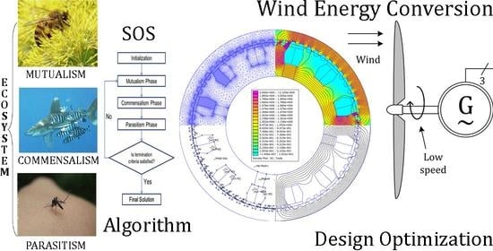
SOS Algorithm Principle

SOS exploits the symbiotic communication strategies that are used by the organisms aiming to stay alive in an ecosystem (population). There are three symbiotic strategies: (a) the mutualism, (b) the commensalism and (c) the parasitism. The process starts with a population, randomly generated, of size N (i.e., number of organisms) with values for the parameters need to be optimized according to their lower and upper bounds (universe of discourse) shown in Table 2. In this phase, the best organism ( X b e s t ) is identified and evaluated. The best organism corresponds to the organism (machine topology) which has a better objective function value (i.e., Equation (8)). Then, the population with the better objective function is updated in each iteration, by using the three aforementioned strategies [37,39]. These phases are mathematically given below:
  • Phase of mutualism: In this phase, two organisms of different species coexist in a relationship in which each finds individual advantages. Specifically, the two random organisms (let us denote them X i , X j ( i j ) ) interact within themselves targeting the enhancement of their chances of survival. The new candidate solutions for X i and X j are obtained from Equation (14).
    X i n e w = X i + r a n d ( 0 , 1 ) ( X b e s t M v × B f 1 ) X j n e w = X j + r a n d ( 0 , 1 ) ( X b e s t M v × B f 2 )
    where
    M v = X i + X j 2
    and
    B f 1 , B f 2 = 1 + r o u n d ( r ) , r [ 1 , 2 ]
    The vector M v is called the “mutuality vector” and describes the relationship between X i and X j . The term ( X b e s t M v ) represents the organisms’ efforts to increase survival. The r a n d ( 0 , 1 ) is a vector of random numbers, while B f 1 and B f 2 are the benefit factors of interaction. They are random numbers (either 1 or 2). It is noted that the interaction may provide partial of total benefit to the organism. The original solutions are replaced by all the better values. Equations (14)–(16) represent the mutuality vector, giving the relationship between X i and X j .
  • Phase of comensalism: According to this symbiotic strategy, one organism ( X i ) takes maximum benefit whereas the other one ( X j ) remains without gaining any benefit and—at the same time—without suffering from the symbiosis. The new candidate solution of X i derives from Equation (17).
    X i n e w = X i + r a n d ( 1 , 1 ) ( X b e s t X j )
    At the above expression, the term ( X b e s t X j ) reflects the benefit advantage to which the organism X i is being profited by the organism X j . The organism X i will be updated if the new fitness values is greater than the previous one.
  • Phase of parasitism: Here, the randomly selected organism X i acts as a parasite. It is modified by a random number. At the same time, the p a r a s i t e _ v e c t o r is created. A randomly chosen organism X j is treated as the parasite’s host. The p a r a s i t e _ v e c t o r and the organism X j fight for survival. If the fitness value of the p a r a s i t e _ v e c t o r is higher than the corresponding one of X j , the X j is damaged and the parasite takes its place in the ecosystem. Otherwise, the X j (having greater fitness) overcomes the p a r a s i t e _ v e c t o r and the parasite’s durability in the ecosystem deteriorates.
The optimization procedure is repeated until the stop criterion is met. In the SOS method, the search for the overall optimal solution (the best solution) is guaranteed, as it can be obtained through the symbiotic relationships between the current solution and one or the other of another random solution and the best solution of the population. Figure 14 shows the SOS algorithm logic in pseudocode form, while in Figure 15 the full algorithm flowchart used here is presented [39].

5. Optimization Results and Discussion

The SOS algorithm has been developed and adapted for the electromagnetic design and optimization of the ORDSPMG. The tuning parameters which were used in this study are:
  • Ecosystem organisms number: e c o s i z e = 50 ;
  • The maximum number of function evaluations: m a x f i t e v a l = 400 × d , where d = 11 is problem’s search variables number (problem dimension);
  • The maximum number of iterations: m a x i t e r = 500 .
A program of the SOS algorithm was developed in the MATLAB environment so that to permit its interaction with a FEA software. The program has been executed on a computer system whose processor has 6 cores/12 threads with clock speed at 3.3 GHz, while its RAM was equal to 16 GB. Three independent sets of simulations were performed, with each set comprised of 5 trial runs, in order to test the SOS algorithm’s robustness. It is noted that the optimal search variables values (obtained by the algorithm for each one of the conducted runs) were always almost identical between them. This proves that the SOS method exhibits robustness and superiority for the examined here electrical machine design problem.
The evolution of the torque density and its inverse (i.e., fitness function vs. function evaluations) is illustrated in (Figure 16). It can be easily seen that the convergence to the optimal design which satisfies all the applied constraints is obtained successfully by the adopted algorithm. The objective function variation, which in our case is the torque density, changes direction continuously over the optimization process (up to approximately 350 function evaluations), which means that the algorithm explores and exploits a large search space in order to converge towards the global optimum.
The values of the 11 search variables of the optimum “ecosystem organism” (optimal machine) obtained, along with the related quantities of interest (torque, mass and torque density) are summarized in Table 3. The resulting torque density, mean torque and mass of active parts are 18.89 Nm/kg, 3504.35 Nm and 185.44 kg respectively. For the given fixed axial length L = 200 mm, and considering the initial specifications given in Table 1, it can be observed that a) the outer rotor diameter is reduced about 5%, which means that that the volume of the machine is also reduced about 25% and b) the torque obtained is about 17% greater than the specified one. Thus, it can be said that the proposed solution fulfills by far the set requirements. Additionally, comparing the results of this work with the corresponding ones obtained in [26] (where the topology designed there had the same specifications but an inner rotor geometry), it can be said that an upgrade of 50% and almost 17% have been achieved regarding torque density and mean torque respectively. It should be noted that the machine cited in [26] is optimized by GA.
The comparison continues with other similar—population based—methods. Recently, in [27], the genetic algorithm (GA) and the particle swarm optimization (PSO) algorithms were applied to the same problem. Table 3 shows the results obtained there, in comparison with those obtained by the SOS algorithm. It can be seen that in terms of active machine mass, SOS provides a reduction of 32.4% compared to GA and 26% compared to PSO. In terms of torque density, SOS provides a solution of 34% increment compared to GA and 21.4% increment compared to PSO. The overall comparison justifies the importance of the SOS algorithm and the use of the proposed final topology in direct-drive wind systems.
The obtained (optimized by SOS) ORDSPMG’s magnetic flux density distribution in different regions is shown in Figure 17 where the rotor has been rotated by 360/64 = 5.625 relatively to the stator from its initial conjunction position. The value of the magnetic flux density on the different parts of the generator was found within acceptable limits (i.e., around 1.65 T). Regarding the teeth of the stator and the rotor, a slight saturation is observed. It should be noted, however, that this slight saturation which is due to the concentration of the flux appearing at the edges of the teeth is considered normal for doubly salient machines.
Further investigations were conducted based on the resulted topology. The variation of the related electromotive forces (EMFs) produced by the generator and their corresponding FFT analysis are shown in Figure 18a,b respectively. For the considered number of turns per phase, equal to 160 turns (40 turns wound around each one of the 4 stator poles comprising one phase), it can be seen that, EMF rms value produced is 160 V at 50 rpm. The inner-rotor counterpart machine studied in [26] (for the same number of turns per phase), produced an rms EMF of 120 V, that is, the proposed topology here provides 33.3% larger induced voltage. From Figure 18b it can be noticed that the amplitude of the second harmonic is approximately 35% of the fundamental. This harmonic affects the waveform of EMF and the power factor and increases the torque ripple. From a quantitative perspective, this harmonic will negatively deteriorate the energy efficiency and will increase the required converter sizing. It should be stated that the optimization process has been performed considering only the rated point of the system. However, further works can be led in the future to consider the whole operating cycle of the system.
Finally, the self inductance value as a function of current, at the two characteristic positions (opposite and conjunction), are depicted in Figure 19. For high values of current (practically above 80 A), the inductances corresponding to the two positions are found equal to 30 mH, allowing the reluctance torque to be neglected compared to the “hybrid torque” (Equation (10)).

6. Analysis of the Torque, Energy Ratio and Losses

As explained in the previous paragraphs, the output torque of the studied machine is composed of the torque which is owed to the stator and rotor saliency, the torque which is due to the interaction between the PM-flux and the coils currents and the torque which is due to the presence of the magnets. Figure 9 illustrates the FEM simulation results of the cogging torque versus rotor position (winding current set to zero). As shown in Figure 9, the value of the cogging torque is small, and its maximum value is approximately 100 Nm (2.85%). So, the cogging torque has minimal effect on the ripple output torque. The hybrid torque and reluctance torque versus current is presented in Figure 8. As shown, there is a slight difference between the hybrid and the reluctance torque. This difference decreases as the current increases.

6.1. Analysis of the Steady-State Torque Including All the Components

According to Equation (10), for the generator operating mode, a positive current must be applied when the inductance and the PM flux decrease. For this, an asysmetric inverter is adopted for the square current [11]. The DC bus voltage of the converter is kept as constant and equal to 800 V. The conducting time θ of the square current is defined θ o n and θ o f f as follows:
θ = θ o f f θ o n
The steady-state total torque (Figure 20) is evaluated for rated electrical speed (50 rpm) and rated current (80 A). The steady-state torque is constantly fluctuating around 3566.2 Nm. The maximum torque value is 3845.2 Nm, and the minimum torque value is 2930 Nm. The torque ripple factor of the machine is calculated by using Equation (19),
R T = ( T m a x T m i n ) T
The torque ripple factor value is around 25%. The torque ripple is mainly caused by a second order harmonic (main harmonic causing the torque ripple), the stator and rotor saliency and current commutation (because of the high value of the phase inductance, the machine current needs some time to reach the current reference when closing the switches. Hence, more than one phase current exists in the conduction period defined in Equation (18). In further works, this torque ripple can be minimized as a function of the mechanical behavior of the system.

6.2. Energy Ratio

In order to evaluate the impact of the machine design on the converter sizing, the power factor is necessary. As the supply currents and voltages are not sinusoidal, different ratios are proposed to evaluate the global efficiency of the system static converter-machine [40,41,42]. In this work, the energy ratio proposed in [40] is used i.e., Equation (20). This ratio does not take into account the structure of the static converter, but it gives an idea of the nominal power of the converter compared to machine power.
P F = W W + W
where W is the magnetic field coenergy and W is the magnetic field energy. In this work, since the machine contains permanent magnets, the W and W are given as follows:
W = W ( θ c o n j ) W ( θ o p p )
W + W = W ( θ c o n j ) W ( θ o p p ) + W ( θ c o n j ) W p m ( θ c o n j )
where W ( θ c o n j ) and W ( θ o p p ) are the magnetic field coenergy at conjunction position and opposition position respectively. W ( θ c o n j ) is the magnetic field energy at conjunction position, and W p m ( θ c o n j ) is the permanent magnet magnetic field energy at conjunction position. From Figure 21, the area ( W + W ) represents the total energy exchanged between the machine and the power converter. The area W represents the maximum energy available for electromechanical conversion. The studied machine reaches an energy ratio of around 0.66 .

6.3. Losses and Efficiency

The Joule losses in the DSPM under study are estimated by:
P j = i = 1 3 R i I i r m s 2
where R i represents the resistance of the phase and I i r m s the rms current of the phase considered. Each phase is supplied by a square current of 50% duty cycle (a current I m is applied during the production of generator torque between 0 and 180 and a zero current during the production of motor torque between 180 and 360 ), thus the Equation (23) becomes:
P j = 1 2 i = 1 3 R i I m 2
In addition, the resistance of a phase is expressed:
R i = N p s N t ρ c u L s p S t = 8 N t 2 ρ c u 2 L + l t k r S s l
where L is the machine length and l t the heads coil length, S s l the area of the slot, k r the fill factor (equal to 0.5), ρ c u is the electrical resistivity of copper and N t the number of turns around a stator pole.
The machine length for an average torque of 3000 Nm (which corresponds to the nominal torque fixed by the specifications indicated in Table 1) is 0.171 m. The maximum Joule losses, corresponding to the supply current of 80 A, are 0.8445 kW. The nominal losses, corresponding to the nominal supply current 60 A (Figure 8), are 0.475 kW. Analytical calculations (not shown here) of losses in magnets, in stator steel and rotor steel were also performed based on the Bertotti method [43]. Table 4 depicts the obtained results. According to this table, the total average iron losses represent 2.34% of the nominal power set by the specifications. So, by taking into account the Joule losses and the iron losses, for a current of 80 A and 60 A (nominal current) the efficiency value is 89.23% and 92.93% respectively.

7. Conclusions

In this paper, the analysis of the design and optimization of an outer rotor doubly salient permanent magnet generator (ORDSPMG), dedicated for a direct-drive wind system, by the SOS algorithm coupled with the finite element method was analyzed and presented. The objective goal was to reduce the total volume of the machine while producing the required torque and respecting all the design constraints. The optimal machine obtained through the optimization process satisfied, in terms of torque density, average torque, cost of materials, output power and overall volume; the specifications which were set for the chosen application and its performance are considered as acceptable. This indicates the flexibility and the capacity of convergence towards the global optimum, the computational efficiency and the robustness of the SOS algorithm method. The performances obtained with the proposed machine topology are by far better than those obtained previously with other similar optimization methods and also than those of the inner rotor counterpart machine studied previously by the authors. These better performances are in terms of the value of the magnetic flux density, the amplitude and the quality of the force, the magnetic induction, the torque density, the average torque, the total volume, etc. That means that the proposed generator performances are largely interesting for direct-drive wind system applications. Even if torque density, which is considered as the criterion to maximize in the optimization process, appears as one of the most important for the application, other criteria such as torque ripple, efficiency and power factor have to be considered. This is why the optimal design result is evaluated a posteriori considering these criteria to check if the results are suitable. In future works, an interesting track will be to use a multiobjective optimization approach to find a compromise between these different criteria.

Author Contributions

Conceptualization, C.G., Y.L.K. and J.-F.C.; methodology, C.G. and Y.L.K.; software & validation, C.G. and Y.L.K.; formal analysis, writing, original draft preparation, writing-review & editing, C.G., Y.L.K., J.-F.C., I.D.C., L.B., R.S., M.E.-H.Z.; visualization, Y.L.K. All authors have read and agreed to the published version of the manuscript.

Funding

This research received no external funding.

Conflicts of Interest

The authors declare no conflict of interest.

References

  1. Xiaojing, W.; Xinyan, Z.; Haojie, S. Mutation Assessment Model for the Potential of Clean Energy Development. In Proceedings of the 2018 2nd IEEE Conference on Energy Internet and Energy System Integration (EI2), Beijing, China, 20–22 October 2018; pp. 1–5. [Google Scholar] [CrossRef]
  2. Infield, D.; Freris, L. Renewable Energy in Power Systems; John Wiley & Sons Inc.: Hoboken, NJ, USA, 2020. [Google Scholar]
  3. Merabet, A.; Al-Durra, A.; Debouza, M.; Tanvir, A.; Eshaft, H. Integral sliding mode control for back-to-back converter of DFIG wind turbine system. IET J. Eng. 2020, 2020, 834–842. [Google Scholar] [CrossRef]
  4. Wicki, S.; Hansen, E.G. Clean energy storage technology in the making: An innovation systems perspective on flywheel energy storage. J. Clean. Prod. 2017, 162, 1118–1134. [Google Scholar] [CrossRef]
  5. Yao, L.; Yang, B.; Cui, H.; Zhuang, J.; YE, J.; Xue, J. Challenges and progresses of energy storage technology and its application in power systems. J. Mod. Power Syst. Clean Energy 2016, 4, 519–528. [Google Scholar] [CrossRef] [Green Version]
  6. Akuru, U.B.; Kamper, M.J. Evaluation of flux switching PM machines for medium-speed wind generator drives. In Proceedings of the 2015 IEEE Energy Conversion Congress and Exposition (ECCE), Montreal, QC, Canada, 20–24 September 2015; pp. 1925–1931. [Google Scholar] [CrossRef]
  7. Schmidt, S.; Vath, A. Comparison of Existing Medium-Speed Drive Train Concepts with a Differential Gearbox Approach; European Wind Energy Association, EWEA: Copenhagen, Denmark, 2015; pp. 179–186. [Google Scholar]
  8. Akuru, U.B.; Kamper, M.J. Comparative advantage of flux switching PM machines for medium-speed wind drives. In Proceedings of the 2015 International Conference on the Domestic Use of Energy (DUE), Cape Town, South Africa, 31 March–1 April 2015; pp. 149–154. [Google Scholar] [CrossRef]
  9. Manne, B.; Kiran Kumar, M.; B. Akuru, U. Design and Performance Assessment of a Small-Scale Ferrite-PM Flux Reversal Wind Generator. Energies 2020, 13, 5565. [Google Scholar] [CrossRef]
  10. Sun, W.; Li, Q.; Sun, L.; Li, L. Development and Investigation of Novel Axial-Field Dual-Rotor Segmented Switched Reluctance Machine. IEEE Trans. Transp. Electrif. 2020, 1–12. [Google Scholar] [CrossRef]
  11. Chen, Y.; Ding, Y.; Zhuang, J.; Zhu, X. Multi-Objective Optimization Design and Multi-Physics Analysis a Double-Stator Permanent-Magnet Doubly Salient Machine. Energies 2018, 11, 2130. [Google Scholar] [CrossRef] [Green Version]
  12. Guerroudj, C.; Saou, R.; Charpentier, J.F.; Boulayoune, A. Optimal Design of a Novel Doubly Salient Permanent Magnet Motors for High Power Ship Propulsion. In Proceedings of the 2018 XXIII International Conference on Electrical Machines (ICEM), Alexandroupoli, Greece, 3–6 September 2018; pp. 2556–2562. [Google Scholar] [CrossRef]
  13. Karnavas, Y.L.; Chasiotis, I.D.; Korkas, C.D.; Amoutzidis, S.K. Modelling and multiobjective optimization analysis of a permanent magnet synchronous motor design. Int. J. Numer. Model. Electron. Netw. Devices Fields 2017, 30, e2232. [Google Scholar] [CrossRef]
  14. Chasiotis, I.D.; Karnavas, Y.L. A Generic Multi-Criteria Design Approach Toward High Power Density and Fault-Tolerant Low-Speed PMSM for Pod Applications. IEEE Trans. Transp. Electrif. 2019, 5, 356–370. [Google Scholar] [CrossRef]
  15. Dmitrievskii, V.; Prakht, V.; Kazakbaev, V. Design Optimization of a Permanent-Magnet Flux-Switching Generator for Direct-Drive Wind Turbines. Energies 2019, 12, 3636. [Google Scholar] [CrossRef] [Green Version]
  16. Liu, H.; Pu, S.; Cao, J.; Yang, X.; Wang, Z. Torque Ripple Mitigation of T-3L Inverter Fed Open-End Doubly-Salient Permanent-Magnet Motor Drives Using Current Hysteresis Control. Energies 2019, 12, 3109. [Google Scholar] [CrossRef] [Green Version]
  17. Sriwannarat, W.; Seangwong, P.; Lounthavong, V.; Khunkitti, S.; Siritaratiwat, A.; Khunkitti, P. An Improvement of Output Power in Doubly Salient Permanent Magnet Generator Using Pole Configuration Adjustment. Energies 2020, 13, 4588. [Google Scholar] [CrossRef]
  18. Rauch, S.E.; Johnson, L.J. Design Principles of Flux-Switch Alternators [includes discussion]. Trans. Am. Inst. Electr. Eng. Part III Power Appar. Syst. 1955, 74, 1261–1268. [Google Scholar] [CrossRef]
  19. Anuchin, A.; Demidova, G.L.; Hao, C.; Zharkov, A.; Bogdanov, A.; Šmídl, V. Continuous Control Set Model Predictive Control of a Switch Reluctance Drive Using Lookup Tables. Energies 2020, 13, 3317. [Google Scholar] [CrossRef]
  20. Chau, K.T.; Li, W.; Lee, C.H. Challenges and opportunities of electric machines for renewable energy. Prog. Electromagn. Res. 2012, 42, 45–74. [Google Scholar] [CrossRef] [Green Version]
  21. Liu, C.; Chau, K.; Jiang, J.; Jian, L. Design of a new outer-rotor permanent magnet hybrid machine for wind power generation. IEEE Trans. Magn. 2008, 44, 1494–1497. [Google Scholar]
  22. Alireza, A. A novel metaheuristic method for solving constrained engineering optimization problems: Crow search algorithm. Comput. Struct. 2016, 169, 1–12. [Google Scholar] [CrossRef]
  23. Rezzoug, A.; Zaïm, M.E.H. Non-Conventional Electrical Machines; John Wiley & Sons Inc.: Hoboken, NJ, USA, 2011. [Google Scholar]
  24. Guerroudj, C.; Saou, R.; Boulayoune, A.; El-hadi Zaïm, M.; Moreau, L. Performance Analysis of Vernier Slotted Doubly Salient Permanent Magnet Generator for Wind Power. Int. J. Hydrogen Energy 2017, 42, 8744–8755. [Google Scholar] [CrossRef]
  25. Bekhouche, L.; Saou, R.; Guerroudj, C.; Kouzou, A.; Zaïm, M.E.H. Electromagnetic Torque Ripple Minimization of Slotted Doubly-Salient-Permanent-Magnet Generator for Wind Turbine Applications. Prog. Electromagn. Res. M 2019, 83, 181–190. [Google Scholar] [CrossRef] [Green Version]
  26. Saou, R.; Zaïm, M.E.H.; Alitouche, K. Optimal Designs and Comparison of the Doubly Salient Permanent Magnet Machine and Flux-reversal Machine in Low-speed Applications. Electr. Power Components Syst. 2008, 36, 914–931. [Google Scholar] [CrossRef]
  27. Guerroudj, C.; Zaïm, M.E.H.; Bekhouche, L.; Saou, R.; RAMELI, A. Comparison of Outer and Inner-Rotor toothed Doubly Salient Permanent Magnet Machine. In Proceedings of the 19th International Symposium on Electromagnetic Fields in Mechatronics, Electrical and Electronic Engineering (ISEF), Nancy, France, 29–31 August 2019; pp. 1–2. [Google Scholar] [CrossRef]
  28. Pyrhönen, J.; Jokinen, T.; Hrabovcová, V. Design of Rotating Electrical Machines, 2nd ed.; John Wiley & Sons Ltd.: Flatbush, NY, USA, 2014. [Google Scholar]
  29. Harkati, N.; Moreau, L.; Zaïm, M.H.; Charpentier, J.F. Optimized design of doubly salient permanent magnet generator taking into account converter constraints. In Proceedings of the International Conference on Electrical Sciences and Technologies in Maghreb (CISTEM), Marrakech, Morocco, 26–28 October 2016; pp. 1–8. [Google Scholar] [CrossRef]
  30. Khazdozian, H.A.; Hadimani, R.L.; Jiles, D.C. Size reduction of permanent magnet generators for wind turbines with higher energy density permanent magnets. In Proceedings of the 2014 North American Power Symposium (NAPS), Pullman, WA, USA, 7–9 September 2014; pp. 1–6. [Google Scholar] [CrossRef]
  31. Guerroudj, C.; Boulayoune, A.; Saou, R.; Zaïm, M.E.H.; Moreau, L. Study of Vernier effect on the EMF of a slotted DSPM generator for wind power applications. In Proceedings of the Conference Intenationale des Energies Renouvelables (CIER), Sousse, Tunisia, 21–23 December 2015. [Google Scholar]
  32. Boulayoune, A.; Guerroudj, C.; Saou, R.; Zaïm, M.E.H. Optimisation par Algorithme génétique et Essaim de particule d une machine a inversion de Flux dédiée à l’éolien. In Proceedings of the Conference Internationale des Energies Renouvelables (CIER), Sousse, Tunisia, 21–23 December 2015. [Google Scholar]
  33. Li, H.; Chen, Z. Overview of different wind generator systems and their comparisons. IET Renew. Power Gener. 2008, 2, 123–138. [Google Scholar] [CrossRef] [Green Version]
  34. Boldea, I.; Tutelea, L. Reluctance Electric Machines: Design and Control; Taylor & Francis Group: New York, NY, USA, 2018. [Google Scholar]
  35. Alexandrova, Y.; Semken, R.S.; Pyrhönen, J. Permanent magnet synchronous generator design solution for large direct-drive wind turbines: Thermal behavior of the LC DD-PMSG. Appl. Therm. Eng. 2014, 65, 554–563. [Google Scholar] [CrossRef]
  36. Lekić, Đ.; Vukosavić, S. Split ratio optimization of high torque density PM BLDC machines considering copper loss density limitation and stator slot leakage. Int. J. Electr. Power Energy Syst. 2018, 100, 231–239. [Google Scholar] [CrossRef]
  37. Cheng, M.Y.; Prayogo, D. Symbiotic Organisms Search: A new metaheuristic optimization algorithm. Comput. Struct. 2014, 139, 98–112. [Google Scholar] [CrossRef]
  38. Prasad, D.; Mukherjee, V. A novel symbiotic organisms search algorithm for optimal power flow of power system with FACTS devices. Eng. Sci. Technol. Int. J. 2016, 19, 79–89. [Google Scholar] [CrossRef] [Green Version]
  39. Karnavas, Y.L.; Chasiotis, I.D.; Pechlivanidou, M.S.C.; Karamanis, E.K.; Kladas, A.G. Azimuth Thruster PMSM Optimization using Symbiotic Organisms Search Algorithm. In Proceedings of the 2020 International Conference on Electrical Machines (ICEM), Göthenburg, Sweden, 23–26 August 2020; Volume 1, pp. 2231–2237. [Google Scholar] [CrossRef]
  40. Lawrenson, P.J.; Stephenson, J.M.; Blenkinsop, P.T.; Corda, J.; Fulton, N.N. Variable-speed switched reluctance motors. IEE Proc. B Electr. Power Appl. 1980, 127, 253–265. [Google Scholar] [CrossRef]
  41. Miller, T.J.E. Converter Volt-Ampere Requirements of the Switched Reluctance Motor Drive. IEEE Trans. Ind. Appl. 1985, IA-21, 1136–1144. [Google Scholar] [CrossRef]
  42. Miller, T.J.E. Switched Reluctance Motors and Their Control; Clarendon Press; Oxford University Press: Oxford, UK, 1993. [Google Scholar]
  43. Bertotti, G. Physical interpretation of eddy current losses in ferromagnetic materials. I. Theoretical considerations. J. Appl. Phys. 1985, 57, 2110–2117. [Google Scholar] [CrossRef]
Figure 1. Typical wind energy conversion systems: (a) Use of a transmission gearbox and high-speed generator, (b) Without a transmission gearbox utilizing a low-speed generator.
Energies 14 02055 g001
Figure 2. Cross-section and constructional details of outer rotor toothed doubly salient permanent magnet generator (ORDSPMG) under study.
Energies 14 02055 g002
Figure 3. Detailed topology view of the examined ORDSPMG.
Energies 14 02055 g003
Figure 4. B-H curve of the M400-50A steel type used.
Energies 14 02055 g004
Figure 5. Relative permeability of the steel’s lamination sheet used.
Energies 14 02055 g005
Figure 6. Important rotor positions of an ORDSPMG (a) “opposite” position, (b) “conjunction” position.
Energies 14 02055 g006
Figure 7. Permanent magnets flux vs. electrical angle.
Energies 14 02055 g007
Figure 8. Hybrid and reluctance torque vs. current.
Energies 14 02055 g008
Figure 9. Cogging torque vs. electrical angle.
Energies 14 02055 g009
Figure 10. Impact of yoke thicknesses on the torque-density (a) stator and (b) rotor.
Energies 14 02055 g010
Figure 11. Stator and rotor teeth geometry impact on torque-density (a) teeth depth and (b) teeth width.
Energies 14 02055 g011
Figure 12. Opening angles impact on the torque density (a) pole angle, (b) slot angle.
Energies 14 02055 g012
Figure 13. Torque density dependence on (a) PM thickness, (b), slot height and (c) current density.
Energies 14 02055 g013
Figure 14. Symbiotic organism search (SOS) algorithm in pseudocode form.
Energies 14 02055 g014
Figure 15. Detailed flowchart of SOS algorithm implemented and applied to ORDSPMG optimization.
Energies 14 02055 g015
Figure 16. Objective function (torque density) and its inverse (fitness function) variation through the evolution of the optimization process.
Energies 14 02055 g016
Figure 17. Optimized ORDSPMG resulted after SOS algorithm application (design/properties, FEA mesh, flux lines and flux density distribution are depicted in combined view).
Energies 14 02055 g017
Figure 18. Obtained ORDSPMG electrical analysis: (a) EMF vs. electrical angle, (b) FFT analysis of EMF.
Energies 14 02055 g018
Figure 19. Phase inductance vs. current, calculated at opposite and conjunction positions.
Energies 14 02055 g019
Figure 20. Total torque waveform of the ORDSPMG under study.
Energies 14 02055 g020
Figure 21. Operating cycle of the machine per phase over an electrical period.
Energies 14 02055 g021
Table 1. Problem specifications.
ParameterValueUnit
Rated speed n50rpm
Rated power P o u t 10kW
Rated torque T o u t 3000Nm
Outer diameter ( 2 × R r o u t )600mm
Axial length L ( f i x e d )200mm
Number of turns per phase160
Copper fill factor0.5
Air-gap thickness g0.5mm
Table 2. Range of optimization variables.
Parameter (Search Variable)Lower LimitUpper Limit
Rotor outer radius, R r o u t 150 mm300 mm
Stator and rotor teeth depth, h s , h r 3 mm15 mm
Magnet thickness, E m 5 mm35 mm
Stator and rotor teeth cyclic ratios, α s 1 , α r 1 0.150.50
Stator and rotor teeth cyclic ratios, α s 2 , α r 2 0.150.50
Coil height, h b 10 mm70 mm
Slot radius, R a R r o u t /3 0.9 × R r o u t
Angular pole opening, β 3 15
Angular slot opening, β a 3 15
Rotor yoke thickness, E r 15 mm50 mm
Stator yoke thickness, E s 15 mm50 mm
Table 3. Final search variable and quantities of importance values found through S O S optimization, along with comparison with other methods.
Method
Parameters/QuantitiesUnitGA [27]PSO [27]SOS (Proposed)
Stator yoke thickness, E s mm37.62334.29840.91
Rotor yoke thickness, E r mm31.66926.0629.66
Coil height, h b mm53.92149.5652.12
Angular pole opening, β 6.5736.8388.61
Angular slot opening, β a 5.7495.9807.53
Slot radius, R a mm190.41202.4218.53
Stator teeth cyclic ratio, α s 1 0.3060.2830.2596
Rotor teeth cyclic ratio, α r 1 0.2580.2580.2596
Stator teeth cyclic ratio, α s 2 0.3900.5000.3939
Rotor teeth cyclic ratio, α r 2 0.3230.4090.3939
Magnet thickness, E m mm20.5827.13327.05
Stator teeth depth, h s mm9.06210.327.7039
Rotor teeth depth, h r mm9.3509.1967.7039
Rotor inner radius, R r i n mm258.97265.00247.846
Output torque (average) T o u t Nm3867.623907.803504.35
Active mass Mkg274.49251.14185.44
Torque densityNm/kg14.0915.5618.89
Table 4. Summarized losses calculation results (through FEA) of ORDSPMG.
Part of the Machine Mean Loss (W)
Stator151.41
Rotor79.81
PM0.377
Total231.596
Publisher’s Note: MDPI stays neutral with regard to jurisdictional claims in published maps and institutional affiliations.

