Article

Optimization and Characteristics Analysis of High Torque Density 12/8 Switched Reluctance Motor Using Metaheuristic Gray Wolf Optimization Algorithm

Department of Mechatronics Engineering, Kyungsung University, Busan 48434, Korea
*
Author to whom correspondence should be addressed.
Energies 2021, 14(7), 2013; https://doi.org/10.3390/en14072013
Submission received: 22 February 2021 / Revised: 30 March 2021 / Accepted: 1 April 2021 / Published: 5 April 2021
(This article belongs to the Special Issue Advances in Motor and Drive)

Abstract

:
In this paper, the optimization and characteristics analysis of a three-phase 12/8 switched reluctance motor (SRM) based on a Grey Wolf Optimizer (GWO) for electric vehicles (EVs) application is presented. This research aims to enhance the output torque density of the proposed SRM. Finite element method (FEM) was used to analyze the characteristics and optimization process of the proposed motor. The proposed metaheuristic GWO combines numerous objective functions and design constraints with different weight factors. Maximum flux density, current density, and motor volume are selected as the optimization constraints, which play a significant role in the optimization process. GWO performs optimization for each iteration and sends it to FEM software to analyze the performance before starting another iteration until the optimized value is found. Simulations are employed to understand the characteristics of the proposed motor. Finally, the optimized prototype motor is manufactured and performance is verified by experiment. It is shown that the torque can be increased by 120% for the same outer volume, by using the proposed method.

Graphical Abstract

1. Introduction

Electric vehicle (EV) has been in operation for over a century. Due to the energy crisis and environmental issues, EVs are going through a resurgence in interest to substitute the usual fossil fuel vehicles. EVs are quiet, require minimum maintenance, and do not emit air pollutants compared to fossil fuel vehicles [1,2]. It is desired that the electric motors for traction have a high average torque, low torque ripple, higher torque density, and higher efficiency to meet the requirements of traction performance of EVs applications [3]. There have been studies on the “best” traction motor drives for EVs applications. The permanent magnet (PM) motors usually come with better results [4,5]. Permanent magnet implementation, depending on its core materials, can significantly increase the efficiency and power density of an electric motor. Rare earth material (REM)-based PMs are the best-known option. However, there are a few concerns regarding the availability of rare earth material [6,7]. Moreover, considering the availability and cost of the rare earth material-based PMs, the motors are expensive to manufacture. In consideration of the cost of PMs, the development of high performance rare-earth free motors for EVs applications has gained a multitude of attentions. In several studies, researchers stated switched reluctance motor (SRM) as an alternative drive for electric vehicles and it is becoming a strong competitor to the other drives. Switched reluctance motor (SRM) is a doubly salient, singly excited machine that is well-known for its simple structure. The stator windings are concentrated and both rotor and stator are merely made up of core lamination stacks with no PMs. This simplicity leads to high robustness and low manufacturing costs compared to other AC machines, which is the main attractive point of SRMs.
However, the operation of SRM is heavily dependent on reluctance torque, SRMs inherently gives lower power and torque density and efficiency compared to PM motors. These problems have to be solved in order to utilize SRM as a traction drive for EVs. So, the first challenging problem of this paper is torque density improvement of the proposed SRM through an optimization process. Generally, the main objective of any optimization method is to make the best use of the benefits of the SRM and minimize its drawbacks. Several types of research have been done on SRMs optimization [8,9,10,11,12,13]. In [8], the optimization process was carried out using a combination of the Seeker Optimization Algorithm (SOA) and finite element method (FEM). The aim of the algorithm was to find the maximum torque at the minimum mass of the entire construction by changing the geometric parameters. A conventional optimization was discussed to optimize the physical dimensions of the SRM [10]. For maximizing the average torque and minimizing torque ripple, Balaji and Kamaraj used the particle swarm optimization method and the stator and rotor pole arc, selected as design variables [11]. Gao et al. introduced a design optimization technique to optimize average torque and reduction in torque ripple by using particle swarm optimization (PSO). The suggested approach led to the development of optimal design parameters such as pole arc, the core length, air gap, etc. [12]. In [13], Ma and Qu proposed a framework for multi-objective optimization based on a hybrid method of design experiments and PSO method.
The optimization algorithms categorized into two types: nature-inspired evolutionary and physics-inspired algorithms. Genetic algorithm (GA), PSO, differential evolution (DE), ant colony optimization (ACO), and cuckoo search (CS) are the most common nature-inspired evolutionary algorithms. The simulated annealing (SA) and center force optimization (CFO) are physics-inspired methods proven in solving global optimization problems [14]. In recent years, the nature-inspired algorithm has been employed in several areas of engineering such as renewable energy, control, microwave applications, power, electrical engineering, pattern recognition, and biomedical engineering [15,16]. The Grey Wolf Optimizer (GWO) algorithm is a recent population-based nature-inspired evolutionary algorithm that was developed by Mirjalili in 2014 [14]. This algorithm has been shown to solve non-convex engineering optimization problems and to achieve optimum results compared to GA, PSO, and DE.
In this paper, the optimization and characteristics analysis of a high torque density three-phase 12/8 SRM based on the GWO algorithm is presented. A prototype electromagnetic design and optimization approach is developed, which makes use of finite element analysis (FEA) simulation tool to estimate the SRM overall performance. The proposed technique is not limited to only the proposed motor, but is relevant to any SRM topologies and dimensions, and no precise modeling is required in advance. In other words, a computerized SRM design and optimization strategy using a Grey Wolf Optimizer (GWO) are proposed. The program flow consists of two independent parts: (a) FEA model of SRM and (b) the optimization procedure. In this optimization, ten design variables were selected and maximum flux density, current density, motor volume were selected as optimization constraints, which plays a significant role in the optimization process.
The introduction to this study which includes previous related researches has been presented above in Section 1. Section 2 below explains each design parameter of SRM and also parameter selection and boundary for optimization. Next, in Section 3, the GWO algorithm is briefly described. The optimization process and results are observed in Section 4 where the initial and optimized models are compared and analyzed. To verify the proposed method, prototype SRM was manufactured according to the design and tested. The experiment results are presented in Section 5. Finally, the summary of this study is shown in the conclusions in Section 6.

2. Design of Proposed SRM

2.1. Design Target

In this paper, a three-phase 12/8 SRM is chosen for EVs application. The design specifications of the motor are shown in Table 1. In this optimization process, the current density of the stator winding and maximum flux density are to be less than or equal to 10 [A/mm2] and 1.70 [T], respectively. The 35PN210 steel is used as the core material for stator and rotor. To achieve a high torque density, the target value is 8 [Nm/L] or higher, which is much higher than the best value of a conventional SRMs, 5 [Nm/L].

2.2. Design Considerations

The SRM has a simple operation principle and construction. The general power equation for an electric motor can be written as:
P w = T e ω
where P w is the electric output power in watts, T e is the output torque in Nm, and ω is the speed in rad/sec, respectively.
In this study, the motor volume and output power are considered 0.5 [L] and 1.8 [kW], respectively. The volume of the motor is determined by the stator outer diameter and motor axial length, including the actual stack or core length and both end-coil length of the stator. Figure 1 shows the SRM topology with its geometric parameters.
The motor volume can be derived as:
V = π 4 D s 2 L a x i a l
where V is the motor volume, D s is the stator outer diameter, and L a x i a l is the motor axial length, correspondingly. According to the motor volume, the rotor outer diameter and the axial length of the motor are calculated.
Figure 2 shows the SRM stator core and winding with its winding parameters. The stator coil end height L c . e n d is derived by:
L c . e n d = 1 + n 1 sin θ d d
where the total number of winding layers is n, and the winding center to center angle is θ d . Total end coil length is derived by:
L T . e n d = 2 L c . e n d + k e r r o r L c . e n d
where total end coil length is L T . e n d and k e r r o r is the winding error constant. The axial length of the stator can be derived as [17,18]:
L a x i a l =   L s t a c k + L T . e n d
where L s t a c k is the stack or core length of the stator and L T . e n d is the stator end-coil length. In the optimization process, the end-coil length has been considered as zero; as a result the axial length is equal to stack length of the stator. The general equation of the stack length of the stator can be derived as:
L s t a c k = k 1 D r
where D r is the rotor outer diameter of the motor and k 1 is constant, for non-servo applications, the range of k 1 is given by [17,18,19],
0.25 < k 1 < 0.70
The general torque equation of SRM can be written as:
T e = k D r 2 L s t a c k
where k is constant and the typical values of k for this application is considered as 5500~20,000 Nm/m3. According to the empirical value of constant k , the output torque is calculated. The selection of the stator and rotor pole arc is one of the most important parts of the design process. Some limitations on these values are specified in [20] and summarized here.
The rotor pole arc angle is greater than the pole arc angle, which can be derived as:
β s β r
The sum of the stator and rotor pole arc are less than or equal to rotor pole pitch [20], which can be derived as:
2 π N r β s + β r
2 π m N r β s π N r
where β s , β r is the stator, rotor pole arc in degree, m is the number of phase and π is in degree, respectively.
The consequence of not following these conditions is that the machine will begin with a positive inductance profile before approaching the minimum value. This leads to an increase in the unaligned inductance value and the torque generation to decrease. The three conditions can be demonstrated in a drawing to summarize a feasible area. It is necessary that the stator and rotor pole angles of the machine located in this area. This area for a 12/8 machine is shown in Figure 3. The zone underneath OF illustrated in (9) and (11) is indicated by the zone above GH, and the zone underneath DE is illustrated in (10). In this study, the stator and rotor pole have a tapper angle, which makes the different pole width at the pole top to the bottom side. The stator and rotor pole width is minimum on top and maximum on the bottom. If the tapper angle is zero, then the minimum pole width is equal to the maximum pole width. Figure 3 shows the graphical representation of the stator and rotor poles. The stator and rotor pole width of SRM can be written as [18,19]:
w s p =   D r + 2 A g sin β s 2
w r p = D r sin β s 2
where w s p , w r p , A g are the stator, rotor pole width and airgap length in millimeter, β s , β r are the stator and rotor pole arc in degree, respectively. In Figure 4, w s p m , w s p denotes the stator maximum and minimum pole width in millimeter, w r p m , w r p are the rotor maximum and minimum pole width in millimeter, τ s , τ r are the stator and rotor tapper angle in degree, respectively.
The stator maximum pole width can be driven based on the following Equations (14)–(18) and Figure 4 and Figure 5, respectively:
R s i =   R s y s r w s p
θ s = π + β s   2 τ s
Δ s = 2 R b c o s θ s 2 4 ( R b 2 R s i 2 )
c s = R b c o s θ s ± Δ s 2
w s p m = 2 c s sin τ s + R b sin β s 2
where R s i , R s , R b are the stator inner, outer and bore radius, y s r is the stator yoke ratio. The calculation process of maximum rotor pole width can be derived based on the following Equations (19)–(23) and Figure 4 and Figure 5, respectively:
R r i =   R s f t y r r w r p
θ r = β r   2 + τ r
Δ r = 2 R r c o s θ r 2 4 ( R r 2 R r i 2 )
c s = R b c o s θ ± Δ r 2
w r p m = 2 c sin τ r + R r sin β s 2
where R r i , R r , R s f t are the rotor inner, outer and shaft radius, y r r is the rotor yoke ratio. The stator yoke thickness has to be a minimum of 0.5 w s p . The range of stator yoke thickness is defined as:
w s p > y s 0.5   w s p
In this study, the fixed and variable parameters of 12/8 SRM were calculated based on the above design consideration and those summarized in Table 2 and Table 3.

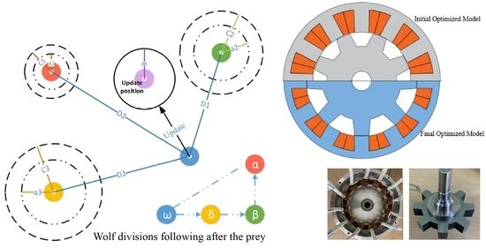
3. The Gray Wolf Optimizer (GWO)

GWO is a recently developed metaheuristic intelligence optimization algorithm for the different engineering application proposed in 2014 by Mirjalili et al. [14], which has good accuracy in global search and convergence. The GWO algorithm works based on the strong social hierarchy and hunting behavior of the wolf population. The population can be categorized as alpha, beta, delta and omega. The alpha, beta, delta and omega wolves flow in terms of social rank from high to low. In the grey wolf population, the best solution is represented as the alpha, the second-best solution as the beta, the third-best solution as delta, and other solutions as omega wolves. In addition to the grey wolves’ social hierarchy, hunting is another vital social comportment of the grey wolves. In the algorithm, hunting processes are executed by the alpha (α), beta (β), and delta (δ) wolves. The omega (ω) or other wolves follow the three wolves to carry on the prey chasing, approaching, tracking, pursuing, harassing, encirclement, and suppression. Finally, the predation process finishes. In GWO, the social hierarchy mathematical model is developed based on the rank of alpha, beta and delta wolves. The hunting behavior of the wolves is mainly tracking, encircling, and attacking the prey. The mathematical expression of the grey wolf encircling behavior can be derived as:
D = C · X p t X t
X t + 1 = X p t A · D
where t specifies the current iteration, A and C are coefficient vectors, X p is the position vector of the prey, D is the distance vector of the wolf, and X indicates the position vector of a grey wolf. The vectors A and C are calculated as follows:
A =   2 a · r 1 -   a
C = 2 · r 2
where a components are linearly reduced from 2 to 0 and r 1 , r 2 are random vectors of [0, 1]. In the optimization process, the possible position of prey can be detected by the alpha (the best candidate solution), beta and delta population. The wolves update their position based on information of alpha, beta, and delta population and mathematical expression can be expressed in Equations (29)–(35) [14,21].
D α = C 1 · X α X
D β = C 2 · X β X
D δ = C 3 · X δ X
X 1 = X α a 1 · D α
X 2 = X β a 2 · D β
X 2 = X δ a 3 · D δ
X t + 1 = X 1 + X 2 + X 3 3
The optimization is to evaluate the prey’s location according to the alpha, beta and delta wolves. Then, the rest of the wolves use the location as a reference and randomly update their locations around the prey. The grey wolves update their positions based on the location information of alpha, beta and delta, as shown in Figure 6 [21].

4. SRM Optimization Process

The SRM optimization process includes the GWO-FEMM (Finite Element Method Magnetics) modelling for FEA-based objective function calculation, optimization and analysis. FEMM is a free software for FEA and it allows freedom in design because the geometry can be drawn simply by connecting dots placed accordingly in the cartesian plane. Therefore, the result of GWO after each iteration is applied to change the geometry by moving the dots and lines in FEMM where the magnetic characteristics can be observed. In this study, the stator outer diameter, rotor diameter, stator pole arc, rotor pole arc, stator tapper angle, rotor tapper angle, stator yoke ratio, rotor yoke ratio, slot fill factor and MMF are selected as optimization variables:
X =   D s ,   D r ,   β s ,   β r ,   τ s ,   τ r ,   y s r ,   y r r ,   F F ,   M M F
The design variables limited by the lower and upper limits of the application and implemented by the heuristic technique:
L o w e r B o u n d   L B   = X L B
U p p e r B o u n d   U B   = X U B
The geometric limits are considered using the design consideration of the motor. During this process the stator outer diameter, stator pole arc, stator pole tapper angle, stator yoke, rotor diameter, rotor pole arc, rotor pole tapper angle, rotor yoke, magnetomotive force, and fill factor are calculated by maintaining the same volumes.

4.1. Modeling of GWO-FEMM Objective Function

In optimization, the GWO-FEMM optimization model is presented, which evaluates the objective function. The objective function is the function of output torque [ T a v g X ] and torque ripple [ T r i p p l e X ]. Additionally, the objective function is calculated based on design constraints: current density less than or equal to 10 [A/mm2] and flux density less than or equal to 1.7 [T]. The output torque and torque ripple are evaluated by FEMM. The torque ripple can be calculated by:
T r i p p l e = T m a x T m i n T a v g × 100 %
where, T r i p p l e , T m a x , T m i n and T a v g denote the torque ripple, maximum torque, minimum torque and average torque, respectively.
The objective function can be derived as:
F i t n e s s   V a l u e   F V = W 1 T a v g X T a v g T + W 2 T r i p p l e T T r i p p l e X
where w 1 , w 2 are weight factors that are satisfying w 1 + w 2 = 1 , T r i p p l e T and T a v g T are the target torque ripple and average torque, respectively. This research aims to enhance the torque density, maximizing output torque and minimizing torque ripple while maintaining the same volume, current density, and flux density based on optimal design parameters. Hence, GWO-FEMM is used to represent the relationship between the torque and torque ripple of design variables, as shown in Figure 7.

4.2. Optimization Process

In this study, the special optimization software was designed in the MATLAB by using the GUI toolbox. In the main program, the input parameter of GUI transfer to MATLAB GWO main program, these design parameters translate to the MATLAB commands and send to the FEMM MATLAB commands for finite element analysis by calling the FEMM. The GWO optimization procedure of SRMs for MATLAB and FEMM is demonstrated in Figure 8.
The variable design parameters are known as the input data. In GUI, variable design parameters are transferred to the GWO to generate random design parameters using GWO initialize constants. Thereafter, the design parameters are transferred to the FEMM software to calculate the magnetic parameter of flux density, current density and compered to magnetic consideration values. If it satisfies the magnetic consideration, the FEMM software calculates the average torque and torque ripple and estimates objective function. Alternatively, if the magnetic considerations are not satisfied, GWO updates the design parameters using initialized constants, and the fitness value is considered zero. The GWO algorithm selects the best three fitness values for each iteration, defined as alpha, beta, and delta fitness values. Each iteration of the GWO update design parameters using initial constants, based on alpha, beta, and delta position. This process repeated with the final iteration number. At the last iteration, the best fitness value and optimal design parameter of GWO sent to the MATLAB main program and plot fitness values evaluation concerning the total iteration number. The population size of this optimization algorithm was 30 and the total number of iterations was considered as 150 [14,22]. The optimization algorithm generates 4500 sets of design parameters, and the FEMM run total of 4500 times to analyze the motor for completing the entire optimization process.

4.3. Optimization Results

In this study, GWO is used to optimize the SRM, and the fitness function includes different values such as the average torque, torque ripple, current density, and the flux density. Figure 9 shows that the fitness values of 12/8 SRM are converged.
Figure 10 illustrate the geometric dimension comparison of the 12/8 initial and final optimized models, respectively.
Table 4 shows the physical parameters of the initial and the final optimized model, respectively. At the aligned position, the flux density for the initial and final optimized model is the same. It also maintained the same volume and current density. It also found that the final optimized model has a higher rotor outer diameter compared to the initial optimized model. The final optimized model contains the lower stator and rotor pole arc. The higher rotor outer diameter and lower value of stator and rotor pole arc help to increased average torque.
The output torque is proportional to the square of the current and the discrepancy of inductance against the rotor position. High inductance slope results in increased output torque. Figure 11a,b show the static torque, inductance and continuous torque of the initial model, respectively. The average torque and torque ripple of the initial model are 3.5 [Nm] and 65%, respectively.
Figure 12a,b show the static torque and inductance profile, and continuous torque of the final optimized model, respectively. The average torque and torque ripple of the optimized model are 4.35 [Nm] and 73%, respectively. The maximum to minimum inductance ratio of the initial and final optimized models are 4.5 and 6.1, respectively.
The SRM efficiency depends on loss. The losses in an SRM are related to copper, core, and mechanical ones. The copper loss depends on phase current and phase resistance. The copper loss can be representing as:
P c u = I p 2 R p
where P c u is the phase copper loss, I p is the phase current and R p is the phase resistance, respectively. The core loss forecast is a crucial factor of the design strategy of the SRM. In the SRM, the core loss depends on the flux density. The core loss is difficult to predict because of the change of flux densities produced by the different frequencies in the stator sections. In addition, the core loss also depends on the shape of the current waveforms of the magnetic circuit in different portions. Therefore, a precise assessment of the core loss in SRM would require decomposition of the frequency and flux density in each section [23,24]. The core loss in an SRM includes hysteresis, eddy current, and excess loss. Consequently, the core loss is obtained using the Bertotti modified equation as [23,24]:
P c o r e = k n f B a + b B + k e f 2 B 2 + k e x f 1.5 B 1.5
where a and b are the constant, B is flux density, f is the frequency, and k n , k e , and k e x are hysteresis, eddy current, and excess coefficients, respectively. The loss P m e c represents energy lost in bearing friction and rotating parts. Mechanical loss P m e c depends on the properties of the lubricant, type of bearing, the load on bearing and the shaft speed. Finally, the total loss P t o t a l in SRM can calculated as:
P t o t a l = P c u + P c o r e + P m e c
Figure 13 shows the torque, power and efficiency curves of the initial and final optimized models, respectively. The initial optimized model shows that the output torque, power and efficiency are 3.50 [Nm], 1.5 [kW] and 88.6 [%] at rated speed, respectively. On the other hand, the optimized model shows that the output torque, power and efficiency are 4.35 [Nm], 1.85 [kW] and 89.4 [%] at rated speed. Finally, the final optimized model offers higher torque, power and efficiency at rated speed compared to the initial one. Moreover, the final modified model provides higher torque and efficiency at the higher and lower speed region. The initial and final optimized motor maintained the same rated speed, and the output powers are 1.5 and 1.85 [kW], respectively. Based on the optimization results of the proposed motor, it can be conculcated that the optimization process has been carried out correctly. The final optimized model has been chosen to manufacture the prototype motor based on the static and dynamic performance analysis.

5. Experimental Results of Prototype 12/8 SRM

A prototype three-phase 12/8 SRM is manufactured for light electric vehicle applications. Figure 14 shows the prototype 12/8 SRM.
The experimental result is executed to verify the performance of the proposed motor. The result can be divided into two parts, static and dynamic. The experimental setup of the prototype motor is presented in Figure 15. The maximum switching frequency of IGBT (Insulated Gate Bipolar Transistor) is 20 [kHz]. The main control board is based on the microcontroller TMS320F28335 with a clock frequency up to 150 [MHz]. The experimental setup included the prototype SRM, power circuit, control board, servo motor, servo drive, and torque sensor.
Figure 16 illustrates the output power and efficiency at rated torque. The experimental results show that the rated torque, output power, rated speed and efficiency are 4.2 [Nm], 1.8 [kW], 4100 [rpm] and 85.6 [%], respectively. The results shows that the manufactured prototype 12/8 SRM is closely matched to the characteristics of the optimized 12/8 SRM. Moreover, the experimental output power, torque and efficiency are reduced by 3.8 [%], 3.5 [%] and 3.7 [%], respectively compared to the simulation. The efficiency discrepancy between the simulation and experimental results is mostly caused by a manufacturing error, mechanical and stray losses. Manufacturing error included a slight difference in winding design (how it is actually wound and resistance). Maximum current in the simulation was 33 [A] and in the experiment was 39 [A] which leads to an increase in copper loss, which is one of the factors of lower efficiency in the experiment. Nevertheless, Table 5 shows the final performance comparison between simulation and experimental results as well as conventional SRMs. The proposed motor torque density is 8.4 [Nm/L], it was increased by 32% compared to our conventional ones. On the other hand, the power density and efficiency are increased by 60% and 1.8%, respectively. Finally, the above comparisons show that the optimized SRM achieved higher torque density, power density, and efficiency compared to conventional ones.

6. Conclusions

This study presents a constrained multi-objective optimization for the optimal design of an SRM based on the meta-heuristic Grey Wolf Optimization (GWO) algorithm. The proposed methodology aims to maximize the torque density of SRM for EVs through geometric optimizations. The proposed method utilizes FEA to observe the characteristic of the motor per iteration, which is crucial in SRM since the motor has highly non-linear magnetic characteristics. GWO algorithm is a recently developed population-based nature-inspired evolutionary algorithm. Without having precise modeling of SRM, GWO can be easily utilized to optimize the parameters according to the objective function, which in this case is torque. FEMM also gives a good degree of freedom and can be linked to various optimization algorithms. GWO modifies the design parameters per iteration which is analyzed through FEA in FEMM until the ‘location’ of the ‘prey’ has been found by the ‘wolves’. The results show that the final optimized model output torque can be increased by about 0.85 Nm compared to the initial model. Simulation and experiment results have proved that the proposed 12/8 SRM could operate at the rated speed of 4100 [rpm] and the torque can be increased by around 120 [%] for the same outer volume.

Author Contributions

Conceptualization, M.S.R.; GWO and FEA software, M.S.R. and P.T.H.; prototype manufacturing, K.-I.J.; validation; M.S.R. and P.T.H.; writing original draft preparation, M.S.R.; writing review and editing, G.F.L.; supervision, J.-W.A. All authors have read and agreed to the published version of the manuscript.

Funding

This work was partially supported by “Human Resources Program in Energy Technology” of the Korea Institute of Energy Technology Evaluation and Planning (KETEP), granted financial resource from the. Ministry of Trade, Industry & Energy, Korea. (No. 20184010201700) and “National Research Foundation of Korea” of Korea. (No. NRF-2020R1G1A1012756).

Institutional Review Board Statement

Not applicable.

Data Availability Statement

Data sharing not applicable.

Conflicts of Interest

The authors declare no conflict of interest.

References

  1. Zeraoulia, M.; Benbouzid, M.; Diallo, D. Electric Motor Drive Selection Issues for HEV Propulsion Systems: A Comparative Study. In 2005 IEEE Vehicle Power and Propulsion Conference; IEEE: Piscataway, NJ, USA, 2005; p. 8. [Google Scholar]
  2. Williamson, S.S.; Emadi, A.; Rajashekara, K. Comprehensive Efficiency Modeling of Electric Traction Motor Drives for Hybrid Electric Vehicle Propulsion Applications. IEEE Trans. Veh. Technol. 2007, 56, 1561–1572. [Google Scholar] [CrossRef]
  3. Zhu, Y.; Wei, W.; Yang, C.; Zhang, Y. Multi-objective optimisation design of two-phase excitation switched reluctance motor for electric vehicles. IET Electr. Power Appl. 2018, 12, 929–937. [Google Scholar] [CrossRef]
  4. Chau, K.T. Electric Vehicle Machines and Drives: Design, Analysis and Application, 1st ed.; Wiley-IEEE Press: Chichester, UK, 2015. [Google Scholar]
  5. Husain, I. Electric and Hybrid Vehicles: Design Fundamentals, 2nd ed.; CRC Press: Boca Raton, FL, USA, 2010. [Google Scholar]
  6. Ahn, J.-W.; Lukman, G.F.L. Switched reluctance motor: Research trends and overview. China Electrotech. Soc. Trans. Electr. Mach. Syst. 2018, 2, 339–347. [Google Scholar] [CrossRef]
  7. Rahman, K.; Fahimi, B.; Suresh, G.; Rajarathnam, A.; Ehsani, M. Advantages of switched reluctance motor applications to EV and HEV: design and control issues. IEEE Trans. Ind. Appl. 2000, 36, 111–121. [Google Scholar] [CrossRef]
  8. Widmer, J.D.; Martin, R.; Mecrow, B.C. Optimisation of an 80 kW Segmental Rotor Switched Reluctance Machine for automotive traction. In 2013 International Electric Machines & Drives Conference; IEEE: Piscataway, NJ, USA, 2013; pp. 427–433. [Google Scholar]
  9. Navardi, M.J.; Babaghorbani, B.; Ketabi, A. Efficiency improvement and torque ripple minimization of Switched Reluctance Motor using FEM and Seeker Optimization Algorithm. Energy Convers. Manag. 2014, 78, 237–244. [Google Scholar] [CrossRef]
  10. Wu, W.; Dunlop, J.; Collocott, S.; Kalan, B. Design optimization of a switched reluctance motor by electromagnetic and thermal finite-element analysis. IEEE Trans. Magn. 2003, 39, 3334–3336. [Google Scholar] [CrossRef]
  11. Balaji, M.; Kamaraj, V. Design optimization of Switched Reluctance Machine using Particle Swarm Optimization. In Proceedings of the 2011 1st International Conference on Electrical Energy Systems, Chennai, India, 3–5 January 2011; pp. 164–169. [Google Scholar]
  12. Gao, J.; Sun, H.; He, L.; Dong, Y.; Zheng, Y. Optimization design of Switched Reluctance Motor based on Particle Swarm Optimization. In Proceedings of the 2011 International Conference on Electrical Machines and Systems, Beijing, China, 20–23 August 2011; pp. 1–5. [Google Scholar]
  13. Ma, C.; Qu, L. Multiobjective Optimization of Switched Reluctance Motors Based on Design of Experiments and Particle Swarm Optimization. IEEE Trans. Energy Convers. 2015, 30, 1144–1153. [Google Scholar] [CrossRef] [Green Version]
  14. Mirjalili, S.; Mirjalili, S.M.; Lewis, A. Grey Wolf Optimizer. Adv. Eng. Softw. 2014, 69, 46–61. [Google Scholar] [CrossRef] [Green Version]
  15. Lei, G.; Zhu, J.; Guo, Y.; Liu, C.; Ma, B. A Review of Design Optimization Methods for Electrical Machines. Energies 2017, 10, 1962. [Google Scholar] [CrossRef] [Green Version]
  16. Ringuest, J.L. Multiobjective Optimization: Behavioral and Computational Considerations; Springer Science and Business Media LLC: Berlin/Heidelberg, Germany, 1992. [Google Scholar]
  17. Bilgin, B.; Jiang, J.W.; Emadi, A. (Eds.) Switched Reluctance Motor Drives: Fundamentals to Applications, 1st ed.; CRC Press: Boca Raton, FL, USA, 2019. [Google Scholar]
  18. Miller, T.J.E. Switched Reluctance Motors and Their Control; Clarendon Press: Hillsboro, OH, USA; Oxford, UK, 1993. [Google Scholar]
  19. Krishnan, R. Switched Reluctance Motor Drives: Modeling, Simulation, Analysis, Design, and Applications, 1st ed.; CRC Press: Boca Raton, FL, USA, 2001. [Google Scholar]
  20. Desai, P.C.; Krishnamurthy, M.; Schofield, N.; Emadi, A. Novel Switched Reluctance Machine Configuration with Higher Number of Rotor Poles Than Stator Poles: Concept to Implementation. IEEE Trans. Ind. Electron. 2009, 57, 649–659. [Google Scholar] [CrossRef]
  21. Dai, S.; Niu, D.; Han, Y. Forecasting of Power Grid Investment in China Based on Support Vector Machine Optimized by Differential Evolution Algorithm and Grey Wolf Optimization Algorithm. Appl. Sci. 2018, 8, 636. [Google Scholar] [CrossRef] [Green Version]
  22. Li, X.; Luk, K.M. The Grey Wolf Optimizer and Its Applications in Electromagnetics. IEEE Trans. Antennas Propag. 2019, 68, 2186–2197. [Google Scholar] [CrossRef]
  23. Chen, Y.; Pillay, P. An improved formula for lamination core loss calculations in machines operating with high frequency and high flux density excitation. In Proceedings of the Conference Record of the 2002 IEEE Industry Applications Conference. 37th IAS Annual Meeting (Cat. No.02CH37344), Pittsburgh, PA, USA, 13–18 October 2002; Volume 2, p. 766. [Google Scholar]
  24. Kampen, D.; Owzareck, M.; Beyer, S.; Parspour, N.; Schmitt, S. Analytical core loss models for electrical steel in power electronic applications. In Proceedings of the 2012 13th International Conference on Optimization of Electrical and Electronic Equipment (OPTIM), Brasov, Romania, 24–26 May 2012; pp. 109–117. [Google Scholar]
Figure 1. Cross sectional view of 12/8 SRM.
Energies 14 02013 g001
Figure 2. End coil calculation of stator winding.
Energies 14 02013 g002
Figure 3. Feasible pole arc angle.
Energies 14 02013 g003
Figure 4. Notations of stator and rotor poles.
Energies 14 02013 g004
Figure 5. Detailed notations of stator and rotor poles.
Energies 14 02013 g005
Figure 6. Updating process of wolves’ position in Grey Wolf Optimizer (GWO).
Energies 14 02013 g006
Figure 7. Modeling of GWO-FEMM (Finite Element Method Magnetics).
Energies 14 02013 g007
Figure 8. Flowchart of GWO-FEMM optimization: (a) overall flow (b) GWO-FEMM.
Energies 14 02013 g008
Figure 9. Fitness convergence curve.
Energies 14 02013 g009
Figure 10. Initial and final optimized models.
Energies 14 02013 g010
Figure 11. Inductance profile and torque of the initial model: (a) Static torque and inductance, (b) Continuous torque.
Energies 14 02013 g011
Figure 12. Inductance profile and torque of the final optimized model: (a) Static torque and inductance, (b) Continuous torque.
Energies 14 02013 g012
Figure 13. Characteristics of proposed SRM.
Energies 14 02013 g013
Figure 14. Prototype motor: (a) Assembled, (b) Stator, (c) Rotor.
Energies 14 02013 g014
Figure 15. Test set-up: (a) Controller, (b,c) Measurement set-up.
Energies 14 02013 g015
Figure 16. Output power and efficiency at rated torque (4.2 Nm): (a) simulation, (b) experimental.
Energies 14 02013 g016
Table 1. Specification of 12/8 switched reluctance motor (SRM).
ParametersValue
Volume [L]0.5
Output power [kW]1.8
Efficiency [%]85
Noise [dB]80
Torque density [Nm/L]≥8
Table 2. Fixed parameters.
ParametersValue
Volume [L]0.5
Air-gap ( A g ) [mm]0.30
Shaft diameter ( D s f t ) [mm]20
Lamination core material35PN210
Lamination thickness [mm]0.35
Table 3. Motor parameters for optimization.
ParametersValue
Stator outer diameter ( D s ) [mm] 150 D s 170
Bore diameter ( D ) [mm] 90 D 120
Stator pole arc ( β s ) [deg] 15 β r 24
Rotor pole arc ( β r ) [deg] 15 β s 20
Stator tapper angle ( τ s ) [deg] 0 τ s 10
Rotor tapper angle ( τ r ) [deg] 0 τ r 10
Stator yoke ratio ( y s r ) 0.45 y s r 0.75
Rotor yoke ratio ( y r r ) 0.6 y r r 2.5
MMF [AT] 400 M M F 1600
Fill factor (FF) [%] 30 F F 45
Table 4. Dimension comparison.
ParametersInitial ValueFinal Value
Stator outer diameter [mm]161.6160
Stack length [mm]20.819.0
Axial length [mm]24.425
Rotor outer diameter [mm]99.6112.9
Shaft diameter [mm]2020
Stator pole arc [deg]16.515
Rotor pole arc [deg]17.115.5
Stator tapper angle [deg]1.71.0
Rotor tapper angle [deg]6.34.5
Table 5. Performance comparison of conventional and proposed SRM.
ParametersConventional SRMsProposed 12/8 SRM
6/48/612/8SimulationExperimental
Output power [kW]0.520.510.501.851.80
Speed [rpm]28004100
Volume [L]0.350.50
Torque [Nm]1.771.741.714.354.20
Torque density [Nm/L]5.104.984.898.608.40
Power density [kW/L]1.491.461.433.703.60
Efficiency [%]83.7084.1483.6589.4085.60
Publisher’s Note: MDPI stays neutral with regard to jurisdictional claims in published maps and institutional affiliations.

