
Electrical and Mechanical Characteristics of a High-Speed Motor for Electric Turbochargers in Relation to Eccentricity


Abstract
1. Introduction
2. Selection of the Pole–Slot Combination and Winding Topology
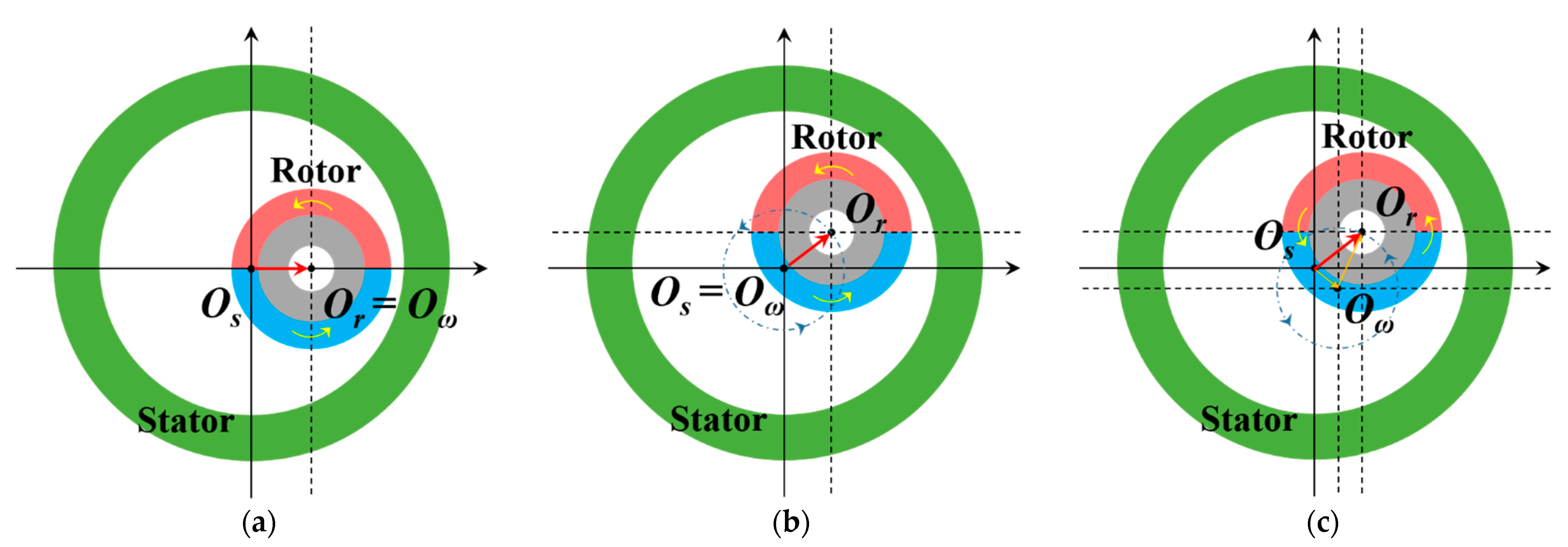
3. Analytical Model According to Eccentricity
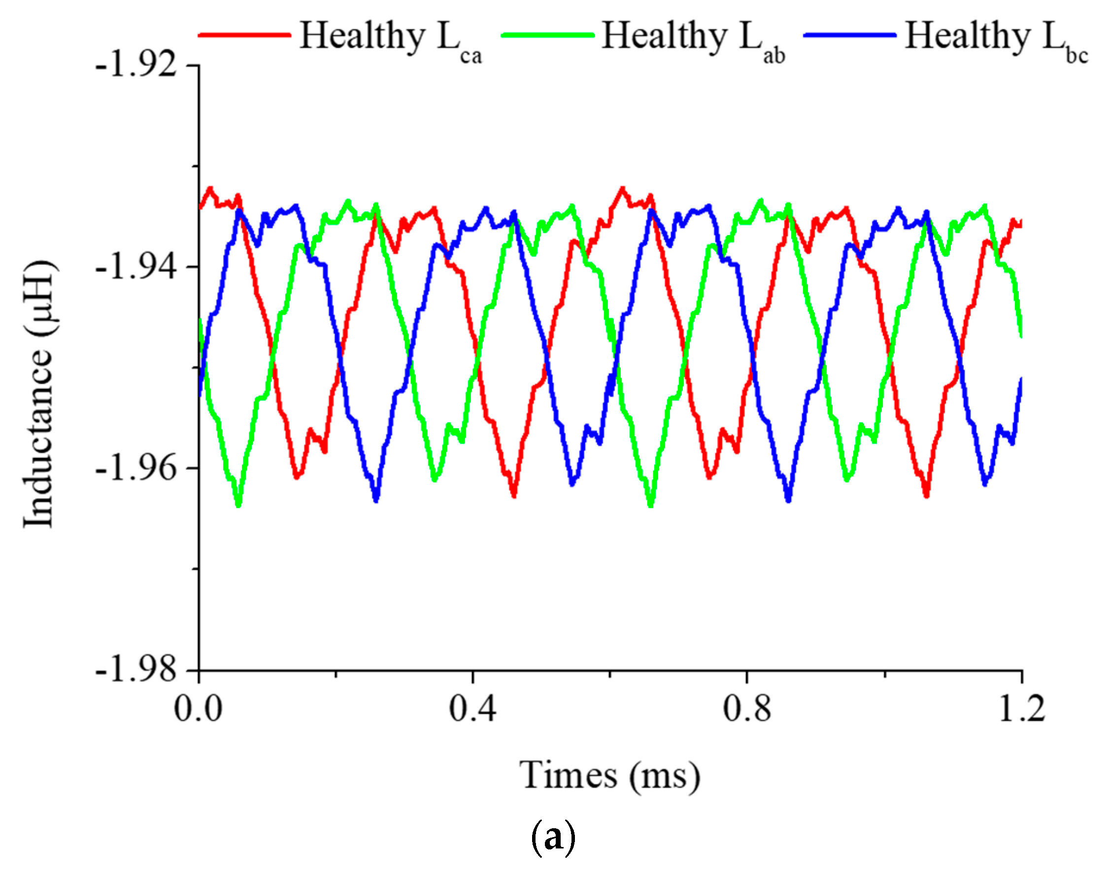
4. Electrical Characteristics
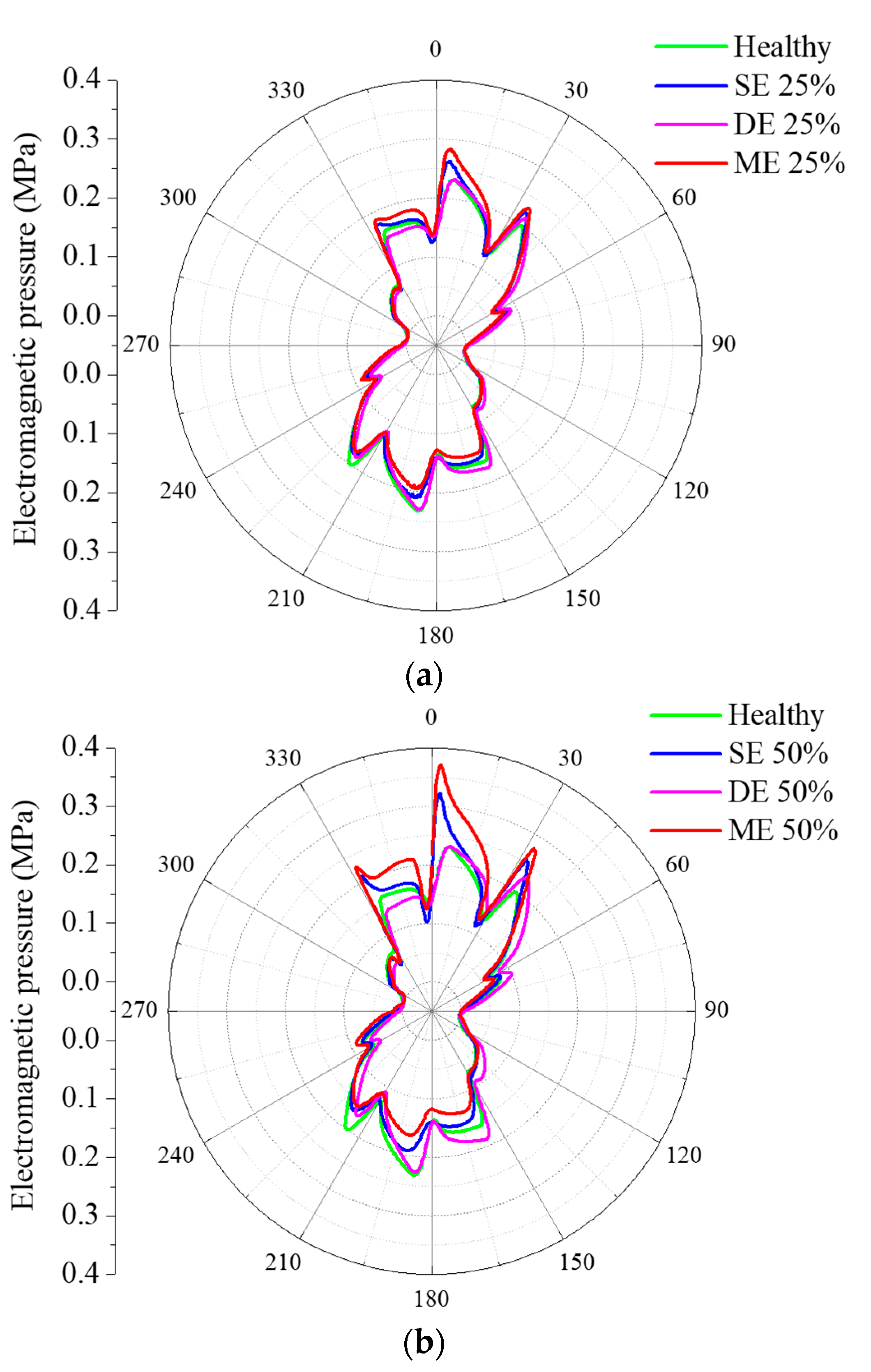
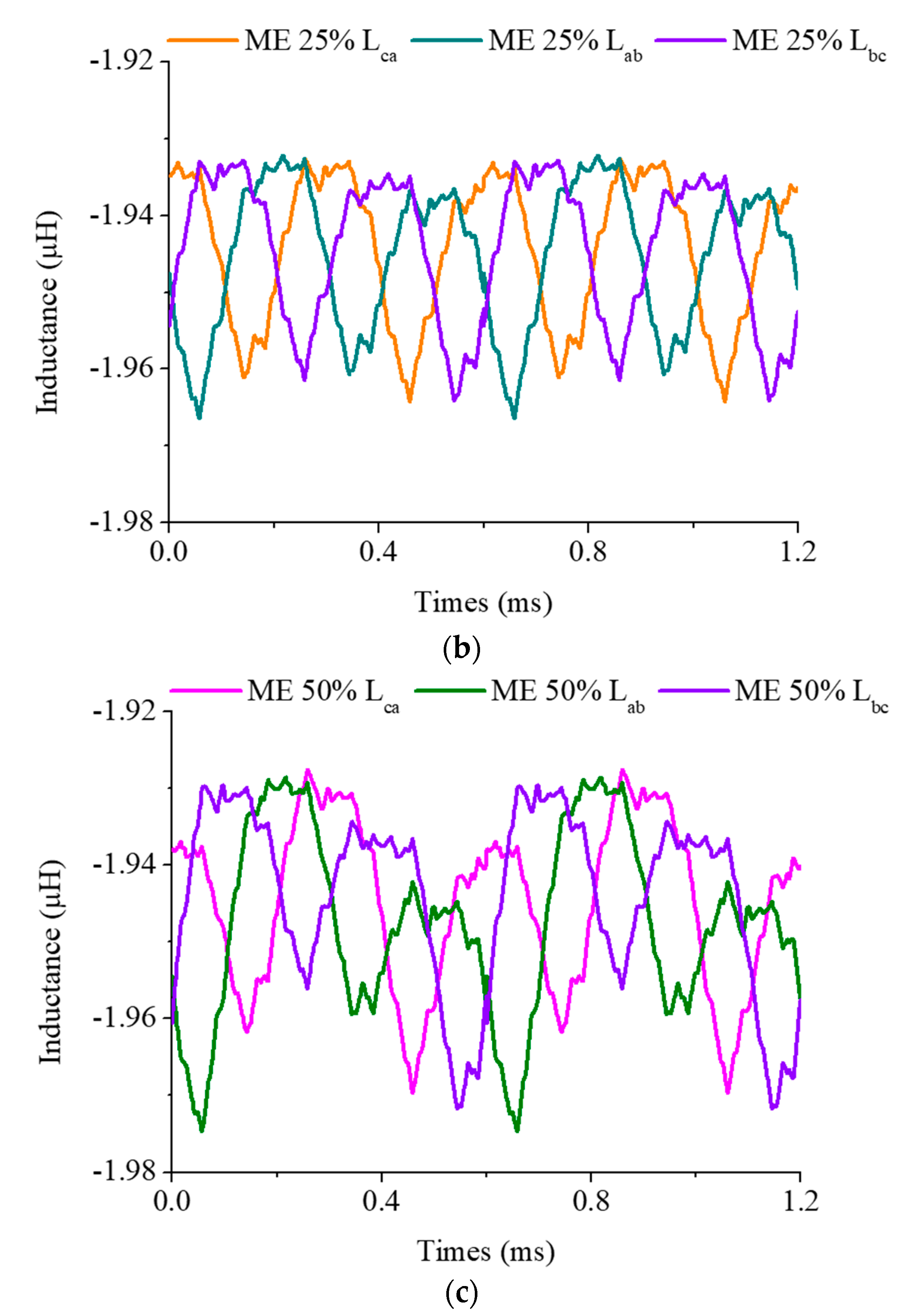
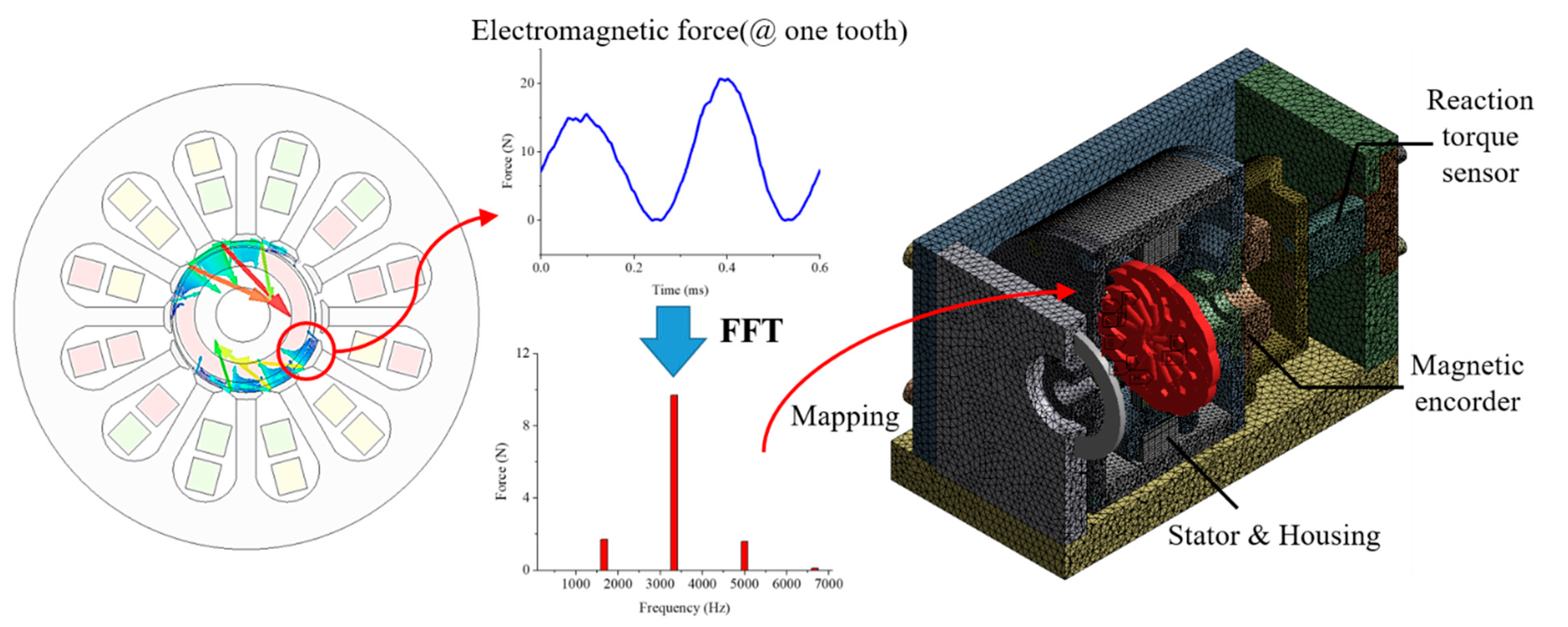
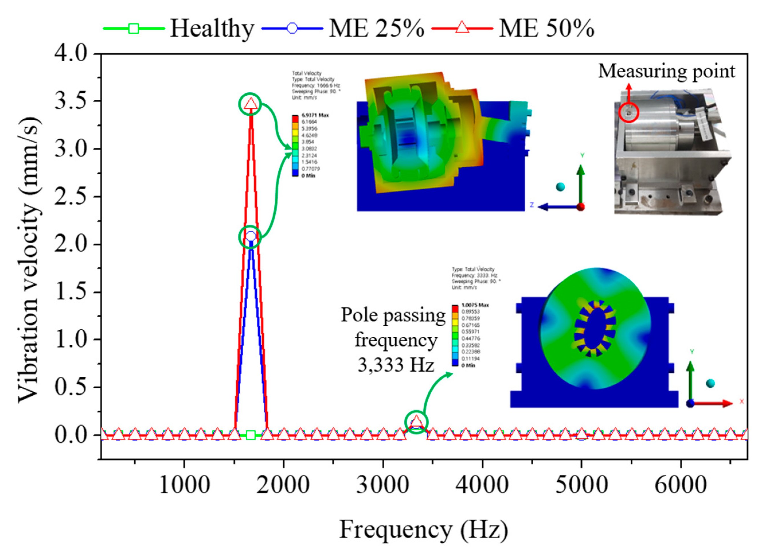
5. Mechanical Characteristics
6. Conclusions
Author Contributions
Funding
Institutional Review Board Statement
Informed Consent Statement
Data Availability Statement
Acknowledgments
Conflicts of Interest
Abbreviations
| BLAC | Brushless alternating current |
| BLDC | Brushless direct current |
| CO2 | Carbon dioxide |
| DE | Dynamic eccentricity |
| EAT | Electrically assisted turbocharger |
| EC | Electric compressor |
| EFIS | Electric forced induction systems |
| EST | Electrically split turbocharger |
| ETC | Electric turbocharger |
| FEA | Finite element analysis |
| FFT | Fast Fourier transform |
| FIS | Forced induction systems |
| GCD | Greatest common divisor |
| IM | Induction motors |
| ME | Mixed eccentricity |
| MMF | Magnetomotive force |
| PM | Permanent magnet |
| PMSM | Permanent magnet synchronous motors |
| PWM | Pulse width modulation |
| SE | Static eccentricity |
| SPMSM | Surface mounted permanent magnet synchronous motors |
| SRM | Switched reluctance motors |
| SVPWM | Space vector pulse width modulation |
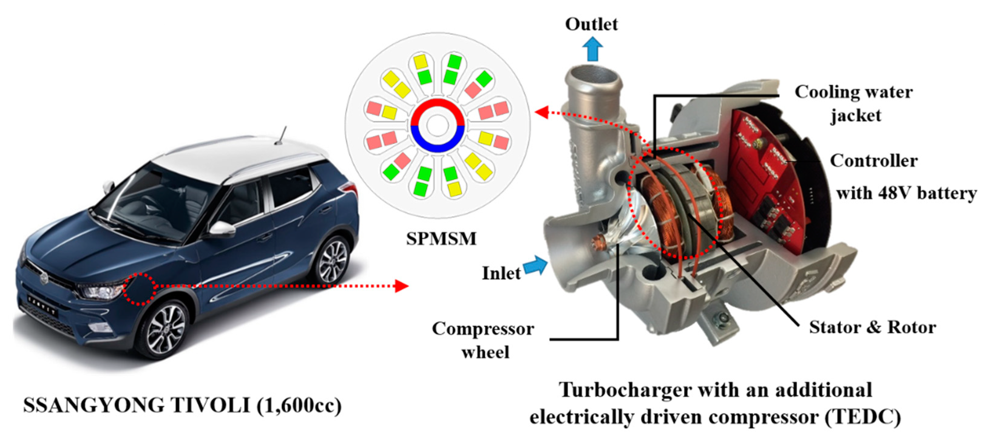
| TEDC | Turbocharger with an additional electrically driven compressor |
| UMP | Unbalanced magnetic pull |
| VGT | Variable geometry turbocharger |
References
- Lee, W.; Schubert, E.; Li, Y.; Li, S.; Bobba, D.; Sarlioglu, B. Overview of Electric Turbocharger and Supercharger for Downsized Internal Combustion Engines. IEEE Trans. Transp. Electrif. 2017, 3, 36–47. [Google Scholar] [CrossRef]
- Hiereth, H.; Prenninger, P. Charging the Internal Combustion Engine, 1st ed.; Springer: Wien, Austria, 2003; pp. 1–4. [Google Scholar]
- Yamashita, Y.; Ibaraki, S.; Sumida, O.; Ebisu, K.I.; An, I.L.; Ogita, I. Development of electric supercharger to facilitate the downsizing of automobile engines. Mitsubishi Heavy Ind. Tech. Rev. 2010, 47, 7–12. [Google Scholar]
- Gödeke, H.; Prevedel, K. Hybrid turbocharger with innovative electric motor. MTZ Worldw. 2014, 75, 26–31. [Google Scholar] [CrossRef]
- Ibaraki, S.; Yamashita, Y.; Sumida, K.; Ogita, H.; Jinnai, Y. Development of the ‘hybrid turbo’, an electrically assisted turbocharger. Mitsubishi Heavy Ind. Tech. Rev. 2006, 43, 1–5. [Google Scholar]
- Woollenweber, W.E.; Halimi, E.M. Motor-Generator Assisted Turbocharging Systems for Use with Internal Combustion Engines and Control Method Therefor. U.S. Patent US5906098A, 25 May 1999. [Google Scholar]
- Arnold, S.; Balis, C.; Barthelet, P.; Poix, E.; Samad, T.; Hampson, G.; Shahed, S.M. Garrett electric boosting systems (EBS) program. Honeywell Turbo Technol. 2005. Available online: https://www.osti.gov/servlets/purl/910121 (accessed on 1 June 2021).
- Hofbauer, P. Method of Controlling an Electrically Assisted Turbocharger. U.S. Patent US20110022289A1, 27 January 2011. [Google Scholar]
- Shimizu, M. Turbocharger with Electric Motor. U.S. Patent US8882478B2, 11 November 2014. [Google Scholar]
- Gill, N. Driving clean technology. In Proceedings of the Cleantech Forum Europe 2012, Munich, Germany, 16–18 April 2012. [Google Scholar]
- Breitbach, H.; Metz, D.; Weiske, S.; Spinner, G. Application and Design of the eBooster from BorgWarner; BorgWarner Turbo System GmbH: Auburn Hills, MI, USA, 2015. [Google Scholar]
- Biwersi, S.; Tavernier, S.; Equoy, S. Electric compressor with high-speed brushless DC motor. MTZ Worldw. 2012, 73, 50–53. [Google Scholar] [CrossRef]
- Menegazzi, P.; Wu, Y.; Thomas, V. Design of an electric supercharger for downsized engines. MTZ Worldw. 2013, 74, 36–41. [Google Scholar] [CrossRef]
- Noguchi, T.; Kano, M. Development of 150,000 r/min, 1.5 kW Permanent-Magnet Motor for Automotive Supercharger. In Proceedings of the 2007 PEDS, Bangkok, Thailand, 27–30 November 2007; pp. 183–188. [Google Scholar]
- Heidrich, T.; Ludwig, F.; Moeckel, A. Investigation of a high-speed drive for turbo-machines. In Proceedings of the Innovative Small Drives and Micro-Motor Systems, 11th GMM/ETG-Symposium, Saarbruecken, Germany, 27–28 September 2017; pp. 1–5. [Google Scholar]
- Lim, M.-S.; Kim, J.-M.; Hwang, Y.S.; Hong, J.-P. Design of an Ultra-High-Speed Permanent-Magnet Motor for an Electric Turbocharger Considering Speed Response Characteristics. IEEE/ASME Trans. Mechatron. 2017, 22, 774–784. [Google Scholar] [CrossRef]
- Hong, D.K.; Lee, T.W.; Jeong, Y.H. Design and Experimental Validation of a High-Speed Electric Turbocharger Motor Considering Variation of the L/D Ratio. IEEE Trans. Magn. 2018, 54, 1–4. [Google Scholar]
- Lee, W.; Kim, J.H.; Choi, W.; Sarlioglu, B. Torque Ripple Minimization Control Technique of High-Speed Single-Phase Brushless DC Motor for Electric Turbocharger. IEEE Trans. Veh. Technol. 2018, 67, 10357–10365. [Google Scholar] [CrossRef]
- Zhao, D.; Stobart, R.; Mason, B. Real-Time Energy Management of the Electric Turbocharger Based on Explicit Model Predictive Control. IEEE Trans. Ind. Electron. 2020, 67, 3126–3137. [Google Scholar] [CrossRef]
- Tran, H.H.; Richard, B.; Gray, K.; Hall, J.M. Developing a performance specification for an electric supercharger to satisfy a range of downsized gasoline engine applications. In Proceedings of the SAE 2016 World Congress & Exhibition, Detroit, MI, USA, 12–14 April 2016. [Google Scholar]
- Baek, S.; Woo, S.; Kim, Y.; Lee, K. Prediction of turbocharged diesel engine performance equipped with an electric supercharger using 1D simulation. Energy 2019, 185, 213–228. [Google Scholar] [CrossRef]
- Lee, T.W.; Baek, S.J.; Lee, K.H. Simulation and Motor Test Considering Engine Experiment Validation of Electric Turbocharger for 1.6L Diesel Engine. IEEE Trans. Transp. Electrif. under review.
- Hofmann, M.; Eckardt, B.; Heckel, T. Inverter technology for high-speed drives like electric turbochargers. In Proceedings of the IKMT 2015, 10. ETG/GMM-Symposium Innovative small Drives and Micro-Motor Systems, Cologne, Germany, 14–15 September 2015; pp. 1–6. [Google Scholar]
- Merdzan, M.; Paulides, J.J.H.; Lomonova, E.A. Comparative analysis of rotor losses in high-speed permanent magnet machines with different winding configurations considering the influence of the inverter PWM. In Proceedings of the 2015 Tenth International Conference on EVER, Monte Carlo, Monaco, 31 March–2 April 2015; pp. 1–8. [Google Scholar]
- Imamura, R.; Lorenz, R.D. Lorenz. Stator Winding MMF Analysis for Variable Flux and Variable Magnetization Pattern PMSMs. IEEE Trans. Ind. Appl. 2020, 56, 2644–2653. [Google Scholar] [CrossRef]
- Karami, M.; Mariun, N.; Rezazadeh Mehrjou, M.; Ab Kadir, M.Z.A.; Misron, N.; Mohd Radzi, M.A. Static eccentricity fault recognition in three-phase line start permanent magnet synchronous motor using finite element method. Math. Probl. Eng. 2014, 2014, 1–12. [Google Scholar] [CrossRef]
- Torkaman, H.; Afjei, E.; Yadegari, P. Static, Dynamic, and Mixed Eccentricity Faults Diagnosis in Switched Reluctance Motors Using Transient Finite Element Method and Experiments. IEEE Trans. Magn. 2012, 48, 2254–2264. [Google Scholar] [CrossRef]
- Hong, J.; Bin Lee, S.; Kral, C.; Haumer, A. Detection of Airgap Eccentricity for Permanent Magnet Synchronous Motors Based on the d-Axis Inductance. IEEE Trans. Power Electron. 2012, 27, 2605–2612. [Google Scholar] [CrossRef]
- He, G.; Huang, Z.; Qin, R.; Chen, D. Numerical Prediction of Electromagnetic Vibration and Noise of Permanent-Magnet Direct Current Commutator Motors with Rotor Eccentricities and Glue Effects. IEEE Trans. Magn. 2012, 48, 1924–1931. [Google Scholar] [CrossRef]


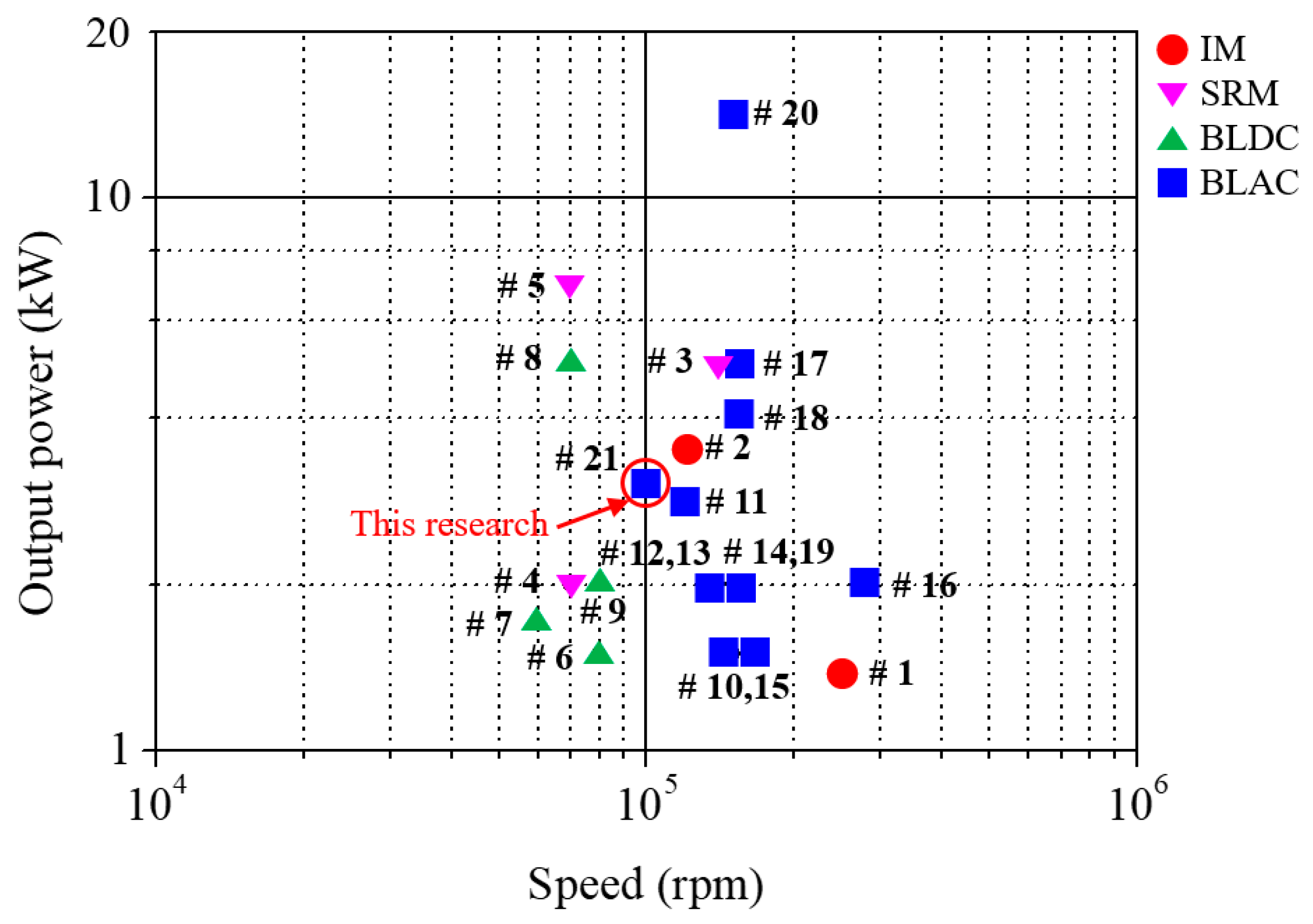
| No. | Motor | Power [kW] | Speed [krpm] | Voltage [Vdc] | Topology | Designed/Studied by |
|---|---|---|---|---|---|---|
| 1 | IM | 1.4 | 250 | 12 | EAT | Honeywell |
| 2 | 2.8 | 120 | 48 | EAT | Honeywell | |
| 3 1 | SRM | 5.0 | 140 | 12/24 | EAT | Loughborough Univ. |
| 4 | 2.0 | 70 | 12 | TEDC | Valeo/CPT | |
| 5 2 | 7.0 | 70 | 48 | TEDC | Valeo/CPT | |
| 6 | BLDC | 1.5 | 80 | 24 | TEDC | WEM-PEC |
| 7 | 1.7 | 60 | 12 | TEDC | BorgWarner | |
| 8 3 | 5.0 | 70 | 48 | TEDC | BorgWarner | |
| 9 | 2.0 | 80 | 48 | TEDC | MMT | |
| 10 | BLAC | 1.5 | 150 | 12 | EC | Nagaoka Univ. |
| 11 | 3.5 | 120 | 48 | EC | Technische Univ. | |
| 12 | 2.0 | 140 | 12 | EC | MHI | |
| 13 | 2.0 | 140 | 12 | EAT | MHI | |
| 14 | 2.0 | 150 | 12 | EAT | IHI | |
| 15 | 1.5 | 160 | 12 | EAT | G+L innotec | |
| 16 | 2.0 | 280 | 12 | EAT | EcoMotor | |
| 17 | 5.0 | 150 | 48 | EAT | EcoMotor | |
| 18 | 4.0 | 150 | 48 | EAT | Hanyang Univ. | |
| 19 | 2.0 | 150 | 12 | EAT | Aeristech | |
| 20 | 14.0 | 150 | 48 | EAT | Aeristech | |
| 21 | 3.0 | 100 | 48 | TEDC | KERI/Keyyang |
| No. | Poles | Slots | Coil Span | Topology | Winding Factor |
|---|---|---|---|---|---|
| 1 | 2 | 3 | 1 | Concentrated | 0.866 |
| 2 | 2 | 6 | 2 | Distributed (short) | 0.866 |
| 3 | 2 | 6 | 3 | Distributed (full) | 1 |
| 4 | 2 | 12 | 5 | Distributed (short) | 0.933 |
| 5 | 2 | 12 | 6 | Distributed (full) | 0.966 |
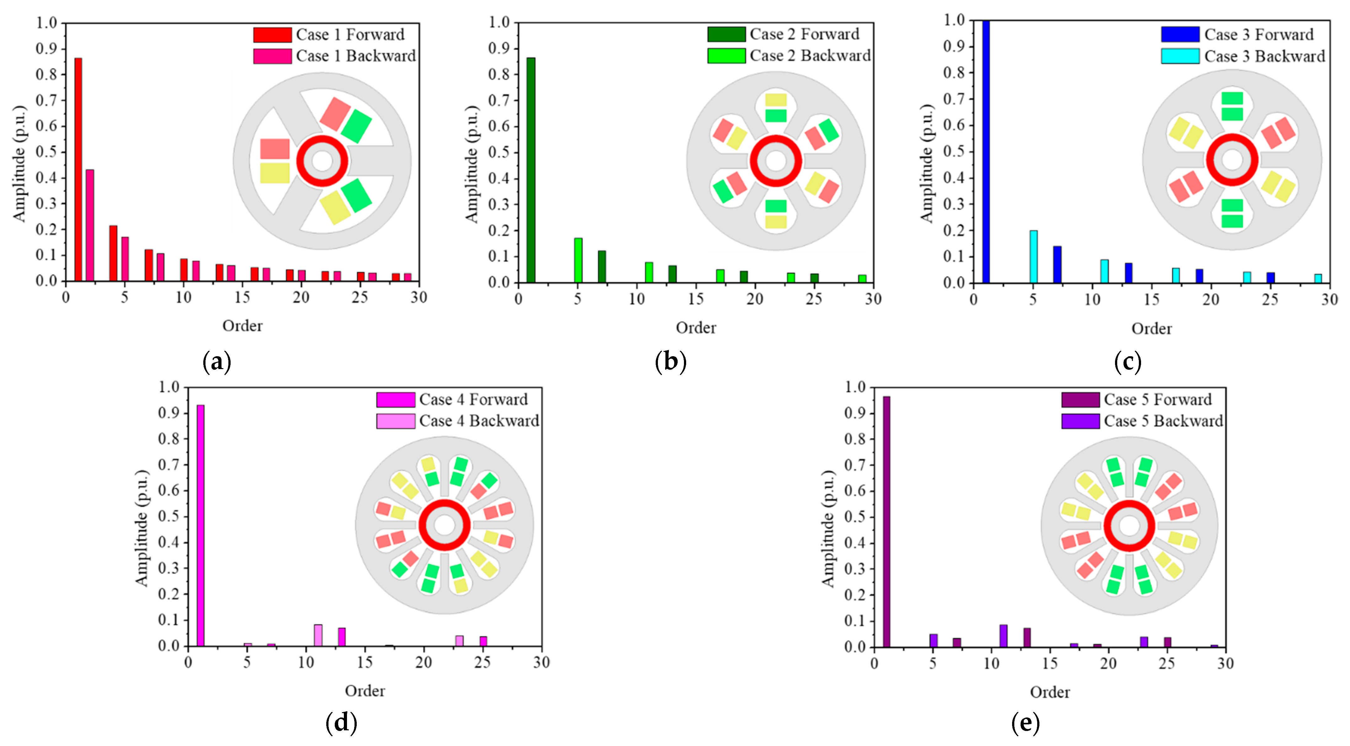
| Harmonic Order | Case 1 | Case 2 | Case 3 | Case 4 | Case 5 |
|---|---|---|---|---|---|
| 2 | 0.43 | 0 | 0 | 0 | 0 |
| 4 | 0.22 | 0 | 0 | 0 | 0 |
| 5 | 0.17 | 0.17 | 0.20 | 0.01 | 0.05 |
| 7 | 0.12 | 0.12 | 0.14 | 0.01 | 0.04 |
| 8 | 0.11 | 0 | 0 | 0 | 0 |
| 10 | 0.09 | 0 | 0 | 0 | 0 |
| 11 | 0.08 | 0.08 | 0.09 | 0.08 | 0.09 |
| 13 | 0.07 | 0.07 | 0.08 | 0.07 | 0.07 |
| Parameter | Case 1 | Case 2 | Case 3 | Case 4 | Case 5 |
|---|---|---|---|---|---|
| Torque (Nm) | 0.2865 | 0.2865 | 0.2865 | 0.2865 | 0.2865 |
| Torque ripple (%) | 15.66 | 3.97 | 4.03 | 1.32 | 1.12 |
| Power (kW) | 3 | 3 | 3 | 3 | 3 |
| Rotor core loss (W) | 4.37 | 3.92 | 3.86 | 4.09 | 4.06 |
| Stator core loss (W) | 48.71 | 43.48 | 43.06 | 51.72 | 52.77 |
| PM loss (W) | 499.23 | 114.63 | 103.99 | 6.07 | 11.70 |
| Winding loss (W) | 58.89 | 68.23 | 66.60 | 55.70 | 63.25 |
| Efficiency (%) | 83.07 | 92.87 | 93.24 | 96.23 | 95.79 |
| Mixed Eccentricity | Lca (μH) | Error (%) | Lab (μH) | Error (%) | Lbc (μH) | Error (%) |
|---|---|---|---|---|---|---|
| 0% | 1.9627 | - | 1.9637 | - | 1.9632 | - |
| 25% | 1.9643 | 0.0815 | 1.9664 | 0.1375 | 1.9641 | 0.0458 |
| 50% | 1.9697 | 0.3567 | 1.9746 | 0.5551 | 1.9718 | 0.4381 |
| Mixed Eccentricity | Sine Waveform (62Arms) | PWM Waveform (64.7Arms) | ||||
|---|---|---|---|---|---|---|
| Torque (mNm) | Ripple (%) | Max. Flux Density (T) | Torque (mNm) | Ripple (%) | Max. Flux Density (T) | |
| 0% | 282 | 0.26 | 1.63 | 285 | 23.1 | 1.61 |
| 25% | 281 | 1.24 | 1.65 | 284 | 24.0 | 1.65 |
| 50% | 275 | 6.1 | 1.73 | 278 | 28.3 | 1.73 |
Publisher’s Note: MDPI stays neutral with regard to jurisdictional claims in published maps and institutional affiliations. |
© 2021 by the authors. Licensee MDPI, Basel, Switzerland. This article is an open access article distributed under the terms and conditions of the Creative Commons Attribution (CC BY) license (https://creativecommons.org/licenses/by/4.0/).
Share and Cite
Lee, T.-W.; Hong, D.-K. Electrical and Mechanical Characteristics of a High-Speed Motor for Electric Turbochargers in Relation to Eccentricity. Energies 2021, 14, 3340. https://doi.org/10.3390/en14113340
Lee T-W, Hong D-K. Electrical and Mechanical Characteristics of a High-Speed Motor for Electric Turbochargers in Relation to Eccentricity. Energies. 2021; 14(11):3340. https://doi.org/10.3390/en14113340
Chicago/Turabian StyleLee, Tae-Woo, and Do-Kwan Hong. 2021. "Electrical and Mechanical Characteristics of a High-Speed Motor for Electric Turbochargers in Relation to Eccentricity" Energies 14, no. 11: 3340. https://doi.org/10.3390/en14113340
APA StyleLee, T.-W., & Hong, D.-K. (2021). Electrical and Mechanical Characteristics of a High-Speed Motor for Electric Turbochargers in Relation to Eccentricity. Energies, 14(11), 3340. https://doi.org/10.3390/en14113340