Article

Multi-Electrode Architecture Modeling and Optimization for Homogeneous Electroporation of Large Volumes of Tissue

Department Electronic Engineering and Communications, I3A, Universidad de Zaragoza, C/María de Luna, 1-50018 Zaragoza, Spain
*
Author to whom correspondence should be addressed.
Energies 2021, 14(7), 1892; https://doi.org/10.3390/en14071892
Submission received: 18 February 2021 / Revised: 22 March 2021 / Accepted: 23 March 2021 / Published: 29 March 2021
(This article belongs to the Special Issue Electromagnetic Modeling in Power Electronics)

Abstract

:
Electroporation is a phenomenon that consists of increasing the permeability of the cell membrane by means of high-intensity electric field application. Nowadays, its clinical application to cancer treatment is one of the most relevant branches within the many areas of electroporation. In this area, it is essential to apply homogeneous treatments to achieve complete removal of tumors and avoid relapse. It is necessary to apply an optimized transmembrane potential at each point of the tissue by means of a homogenous electric field application and appropriated electric field orientation. Nevertheless, biological tissues are composed of wide variety, heterogeneous and anisotropic structures and, consequently, predicting the applied electric field distribution is complex. Consequently, by applying the parallel-needle electrodes and single-output generators, homogeneous and predictable treatments are difficult to obtain, often requiring several repositioning/application processes that may leave untreated areas. This paper proposes the use of multi-electrode structure to apply a wide range of electric field vectors to enhance the homogeneity of the treatment. To achieve this aim, a new multi-electrode parallel-plate configuration is proposed to improve the treatment in combination with a multiple-output generator. One method for optimizing the electric field pattern application is studied, and simulation and experimental results are presented and discussed, proving the feasibility of the proposed approach.

1. Introduction

Electroporation is a phenomenon based on the change in the permeability of the cell membrane by applying an electric field [1,2,3,4,5]. This electric field produces a strong change of transmembrane potential and, consequently, this induced potential can trigger different mechanisms that change the properties of the membrane [6] (Figure 1).
Figure 1 shows how the electroporation has been classified according to the effect produced in the cells depending on the intensity of the applied electric field, in reversible electroporation (RE), and irreversible electroporation (IRE). RE causes temporary permeabilization and is typically used to improve drug absorption, whereas IRE causes cell death, being used as an ablation mechanism with no thermal effect [7].
This paper focuses on the use of electroporation for oncological electrosurgery. In this subject, electroporation has great advantages including:
The treatment efficacy is not depended on thermal effect, this allows treating high blood perfusion tissues, and it does not produce thermal damage [8,9].
This technique does not destroy blood vessels structures, this allows the preservation of more healthy tissue [1,3,4,5].
Electroporation is compatible with many of the current treatments, such as radiotherapy and chemotherapy, being an effective adjuvant mechanism [6].
In electroporation, an adequate distribution of the electric field is essential to achieve a homogeneous and safe treatment. Electroporation is applied using differential electrodes; at present, the two most used electrodes for the application of the treatment are: parallel-needle electrodes as shown in Figure 2a and parallel-plate electrodes as shown in Figure 2e.
Currently, the most commonly used electrodes are parallel-needle electrodes [10,11,12], as they normally allow quick and easy placement. The main limitation of needle-based electrodes is that they create an irregular electric field [13], which is concentrated in several points producing undesired thermal effects [14]. In Figure 2c,d, a simulation of the electric field produced by two needle electrodes has been represented. Also, this type of electrode normally requires several repositioning/application processes to treat large volumes [10,15]. For this reason, this paper is focused on the study of parallel-plate electrodes [3,16,17,18] to achieve adequate electric field distribution [19,20], as can be seen in Figure 2f–h.
Biological tissues are complex structures [21] and, for this reason, it is complicated to treat a large volume in a homogeneous way by applying a single electric field vector. In this sense, each spatial point of a tissue has an optimal direction in which the induced transmembrane potential is maximized. This direction changes due to tissue heterogeneity, conductivity variations, and the different cell geometry, among other factors. Nowadays, the most extended method to apply more than one electric field vector is to physically reposition them [22,23,24,25]. This procedure is not always available, and in the case of needle electrodes, repositioning the electrodes increases the damage and extend the treatment.
The objective of this paper is to propose and validate a matrix parallel-plate electrode (MPPE) [26]. This electrode has the advantages of state-of-the-art parallel-plate electrodes, which allow treating large volumes of tissue and apply more uniform electric field than needle-based electrodes. Also, unlike state-of-the-art parallel-plate electrodes, the proposed structure is composed of different electrically insulated conductive electrode cells, allowing the application of a wide variety of electric field vectors. The rotation of the electric field at each point of the tissue will also allow the transmembrane potential to be applied more efficiently, thus achieving more focused and homogeneous treatment.
Based on a conference publication [26], this paper delves into the analysis of the MPPE, adds experimental validation of the MPPE, and rethinks and expands the optimization of the electrode. Also, for the experimental validation it has been necessary to develop a multi-output generator, considering that MPPE requires as many outputs as the proposed multi-electrode electrode cells.
The remainder of this paper is organized as follows—Section 2 describes the basic aspects of the proposed multi-electrode, and details the model carried out and its evaluation. In Section 3, the main experimental results proving the feasibility of this proposal and an example of optimization are included. Finally, the conclusions of this paper are drawn in Section 4.

2. Materials and Methods

2.1. Proposed Multi-Electrode Architecture

Despite its safety and efficacy, electroporation suffers from several handicaps. One of the challenges of electroporation is to achieve a homogeneous treatment on all types of tissues despite their heterogeneity and anisotropy. To overcome this limitation, this paper proposes the design of a new multi-electrode that allows to apply wide variety of electric field vectors without manipulating the electrode. The MPPE is the proposed multi-electrode to improve electroporation homogeneity.

2.1.1. Proposed Multi-Electrode Geometries

Two geometries of MPPE have been studied, considering square or circular electrodes. These electrodes are made up of nine Cij electrode cells, as it can be seen in Figure 3. Each electrode cell is made of conductive material and it is electrically isolated from the others. The main geometric parameters are: LI is the side of the square electrode cell and LE is the total side of the square electrode including the insulation; RI is the radius of the circular center electrode cell and RE is the total radius of the circular electrode including the insulation.
Considering that the proposed electrodes consist of 9 electrode cells, it is possible to apply more than 40 different electric field vectors. Increasing the number of electrode cells increases the number of electric field vectors that can be applied, but also leads to a complex generator implementation. The two proposed geometries have been selected with a number of electrode cells that can be controlled in an easy way, varying the inclination of the applied electric field vectors by means of their central electrode cell size. These allow the proposed electrodes to apply electric field vectors in a flexible way.

2.1.2. Operation of Proposed Multi-Electrode

To use the MPPE as well as to analyze its results, different strategies have been proposed. The studied electrodes have been made up of 9 isolated electrode cells, with different applied voltages to obtain the desired electric field distribution. As in state-of-the-art parallel-plate electrodes, two electrodes are used differentially, being necessary to establish and control up to 2 × 9 different voltages. Electroporation is based on the application of electric field, for this reason, it is necessary to control the applied voltages as a function of the distance between the electrode cells to apply the desired electric field. Moreover, unlike parallel-plate electrodes, multiple electric field vectors are applied at each point, so the application protocols and the evaluation of the results must be different.
In the case of parallel-plate electrodes, the only thing that can be controlled is the applied voltage between their differential plates, and in this way, it is controlled a single electric field vector. Furthermore, the proposed multi-electrode allows to apply voltage between different combinations of the electrode cells that compose it. Controlling the voltage of MPPE electrode cells allows to apply different electric field vectors An at each point of the tissue. To control the different electrode cell settings (CS), a matrix system is proposed that relates the voltages applied to each of the electrode cells with the n electric field vectors that can be applied to each point of the tissue.
Figure 4a shows a schematic of topology proposed to control a circular MPPE of 9 electrode cells. This topology with the designed generator applies a voltage V_Cnn to each electrode cell. Two direct voltage sources (Vcc and −Vcc) have been used, one positive and other negative, which can be connected by switching devices to both the upper and lower electrode cells and this allows to apply bipolar electric field pulses. Moreover, the electrode cells of the two electrodes have been connected by independent switching devices. So, the voltage is only applied in the selected electrode cells of the electrode. Each of these CS will produce at each point of the tissue Pi an electric field vector An as can be seen in Figure 4. by sequentially applying of 32 CS in the circular electrode, the different electric field vectors represented in Figure 4b,c can be obtained.
When a uniform electric field is applied in a single direction to a biological tissue, a transmembrane potential is induced in the membranes of its cells. The intensity of this potential at each point of the membrane depends on the applied normal electric field. The main advantage of the proposed electrode over traditional flat plates is that the area of the cell membrane where the transmembrane potential is concentrated can be changed. This is a great advantage, due to the geometry and imperfections of cell membrane, its dielectric strength is not constant over its entire surface and has areas that are more susceptible to electroporation. The proposed electrode allows applying several electric field vectors by means of different CSs that can concentrate the electric field in different areas of the membrane, therefore it is possible to find an electric field vector or a combination that allows electroporating the cells of the tissue in a more homogeneous and easy way.
With the different systems that have been proposed it is possible to control the operation of the electrode, and it is necessary to establish how to model and evaluate its operation and results.

2.2. MPPE Modeling and Evaluation

Two finite element models have been developed. These types of models are used in electroporation to plan treatments estimating the volumes in which the electric field has exceeded the electroporation threshold. Unlike these, the models have been created focusing on the study of the module and the direction of the applied electric field. In addition, the models do not evaluate a single electric field application, as so it is studied the relationship of the different electric field vectors applied at each point of the tissue by n CSs. This is necessary as the use of MPPE is based on improving the treatment homogeneity applying wide variety of electric field vectors, and not a single vector. This section presents the models developed and how their results have been evaluated.

2.2.1. MPPE Model

With the objective of modelling, the proposed MPPE and improve their design, two finite element models have been created using the software COMSOL Multiphysics. These are stationary models developed with the Electric Currents block of the AC/DC module (Figure 5). The meshed models can be seen in Figure 5a,e. These models allow to analyze the direction and intensity of the electric field at each point of the tissue, assuming ideal conditions, as can be seen in Figure 5b–d,f–h.
The model consists of two MPPE made of FR4 as electrical insulation material, and steel as conductive material. A biological tissue of a thickness of Tt is placed in between the electrodes. To model the electrical behavior of the tissue, the electrical conductivity in each point depends on the electric field applied in this point. This relationship depends on measured parameters of the tissue [21,27].
Conductivity behavior of the tissue represented in Figure 6 is described in (1) where σ0 and σf are the initial and final electric conductivities of the tissue, respectively. Field Eth models the electric field in which the conductivity reaches half of its maximum value. Finally, the constant Kv controls the slope of the curve.
  σ ( | E | ) = ( σ 0 + σ f σ 0 2 ( 1 + tanh ( K v ( E E t h ) ) ) ) .
Table 1 lists the main electrical parameters used in the models presented. All data has been extracted from previous research [27,28]. As it can be seen in Figure 6, two types of tissue have been modeled. One handicap of electrosurgery is the strong differences in electrical conductivity between tissues. Specifically, in tumor electroporation, the electric field is concentrated in healthy tissue as it is a worse electrical conductor than the tumor. In past research, the conductivity measured in tumors is three times higher than that of healthy tissues [29].
In this model, the external surface is considered to be electrically isolated except for the surfaces where the electric potential is applied, which are the active electrode cells. Isotropic and homogeneous electrical properties in all the volumes are assumed. The tissue has been modeled without taking into account the structure and geometry of the cells, assuming an homogeneous block with equivalent electrical properties; and the effects of temperature on conductivity have been considered negligible because, despite the high instantaneous power applied, the pulses applied in the experiment had a duration of 100 µs.

2.2.2. Evaluation of Independent Electric Field Vectors

The objective of the proposed electrode is to apply the electric field at each point with a modulus above the objective threshold and an appropriate orientation. Due to the difficulty of achieving a homogeneous treatment by applying an electric field in only one direction, the MPPE applies n different vectors to achieve the application of electric field in a direction as optimal as possible. The perfect way to apply the vectors would be a homogeneous distribution, since if the vectors are not sufficiently out of phase with each other they can have the same effect as applying a single vector.
In order to evaluate the MPPE effect, a methodology has been proposed to calculate the number of independent electric field vectors applied at each point. In this subject, two vectors are independent when the angle between them is greater than a set threshold. However, in the case of applying n vectors it is necessary to ensure that each vector meets this condition with the other n-1 vectors. Increasing the number of independent electric field vectors applied at a point, it is more probable to apply the field in the optimal way. Calculating the number of independent electric field vectors applied at each point, it is possible to know the volumes in which the MPPE has been most effective.
Taking into account the above, the first step to evaluate the model is simulating the n electric field distributions produced by the n CS. At each point Pi of the model, the n vectors of electric field are evaluated as can be seen in Figure 7d. In this example three different configurations have been applied. At each Pi the modulus of the three applied electric field vectors is evaluated, and to consider that an electric field vector has been effective, its modulus must be greater than the electroporation threshold Elim. In the example, the three vectors applied in P1, have a modulus above the objective threshold, and therefore it is necessary to calculate if the three vectors are independent. To consider these vectors independent, the angle of each vector with the others must be between established thresholds θmin and θmax. Therefore, the first step is to calculate the angles α1, β1, and Ω1 (Figure 7a–c) which are all the possible relationships between the three electric field vectors applied on P1 of the example. These three vectors are considered independent if θmax > Ω1 > θmin, θmax > β1> θmin and θmax > α1 > θmin, that is, if all angle relationships are above the objective threshold and therefore the three vectors are well distributed. Moreover, if θmax > β1 > θmin, θmax > Ω1 > θmin, and α1 < θmin or α1 > θmax the red and yellow vector are considered to be applied almost collinearly, since the angle between them is considered not above the objective threshold. Consequently, they will produce very similar effect and only one can be considered as an independent vector. Moreover, if θmax > Ω1 > θmin, α1 < θmin or α1 > θmax, and β1 < θmin or β1> θmax the angular relationship of the yellow vector with the red and blue vectors is insufficient but between the red and blue vectors the angular relationship is above the objective threshold. Therefore, they can produce different effects at the point P1 and therefore only the yellow vector is not considered independent. Finally, if, α1 < θmin or α1 > θmax, β1 < θmin or β1> θmax and, α1 < θmin or Ω1 > θmax three vectors are considered to create the same effect and, therefore, in the point P1 only has been applied one independent electric field vector. This process is carried out in the i points of the model and next it is estimated the percentage that has been treated with 1, 2 or 3 independent electric field vectors. This methodology has been implemented in both models to evaluate the effectiveness of the different designs by applying n different CSs.
With the methods presented to operate the electrodes, to control the applied electric field, and to evaluate the models carried out, in the following section the results obtained are presented.

3. Experimental and Simulation Results and Discussion

The objective of this section is to prove the feasibility of the proposed MPPE design and to present an example of optimization for a theoretical case.
Both the model and the experiments have been carried out on potato tissue. The behavior of the electroporation of vegetal tissue is documented [21,30], and specifically potatoes allow us to carry out an in-vivo experimentation to validate the proposed models. Figure 8 shows the setup used in the experiments and the prototype under development.
The setup used in the experiment is composed of three parts:
  • High voltage generator. This test-bench subset consists of high voltage monitoring/acquiring: an 8-bit LeCroy oscilloscope Wavesurfer 3024, three differential high-voltage probes LeCroy HVD3206, and one Pearson current monitor model 110.
  • Electroporation ad hoc multioutput generator, which has been designed to be able to power eighteen outputs and to provide online impedance measurements [27]. The proposed generator is based on a multiple-output structure featuring IGBT (1700-V 100-A 3-phase IGBT power module FS100R17N3E4) an MOSFET (40-V NVMTS0D4N04CTXG MOSFETs) devices [31]. This implementation allows high-performance omnidirectional electroporation treatments.
  • Experimentation area, where the potato specimens are carved and placed.
The experimentation developed, and the results obtained by experimentation on potato tissue are described below.

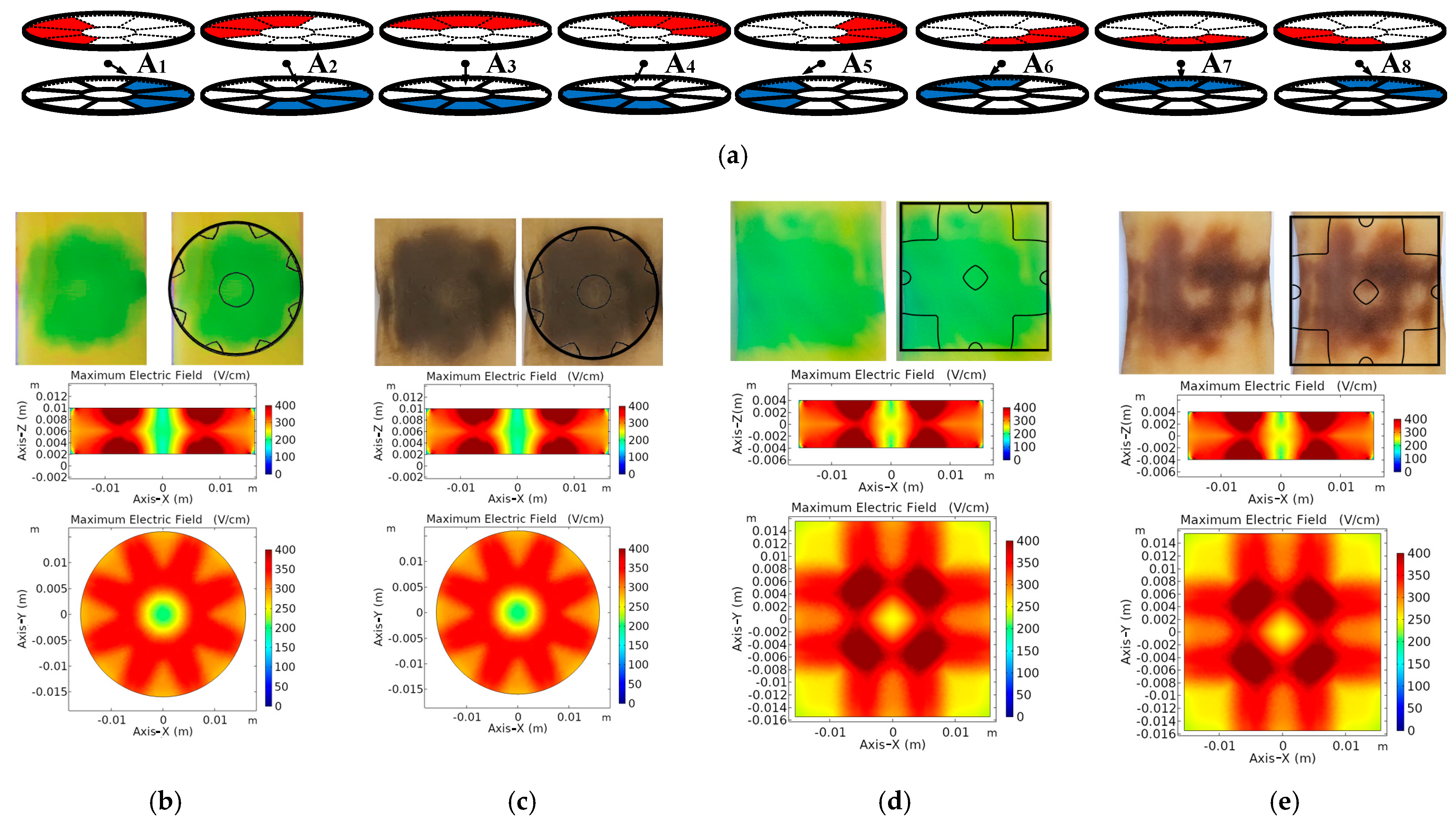
3.1. Electric Field Distribution

There are direct and indirect methods of studying the effects of electroporation. The most widespread indirect method to observe the effect of electroporation in real time is the study of the change in impedance in the tissue. The problem is that this method only gives a global idea of the state of the tissue, and to compare the results of the model it is not necessary to study the effect in real time. Histopathological methods allow a much more accurate understanding of the state of each part of the tissue. In this subject, different techniques have been developed that allow to know the tissue state in a visual way. In this paper, two different techniques have been used that allow studying the distribution of the electric field by means of the coloration of the tissue. First, dye [32] was used to color the areas most affected by electroporation, the intensity of the dye is proportional to the electric field that has been applied. The other technique used [21] is the removal of the tissue after natural degradation. It has already been described that, if the tissue is left to rest for a few hours, it deteriorates naturally, darkening the areas affected by the treatment in proportion to the intensity of the treatment applied.
To validate these models, the experiments represented in Figure 9 and Figure 10 have been carried out. For these experiments, electrodes with a square electrode cell side of 1 cm spaced 0.8 cm have been used in addition to a 1 mm spacing between electrode cells to ensure electrical insulation, and in the circular case, electrodes with equal interior and exterior surfaces to the square case and an equal spacing have been used.
It can be seen in Figure 9a the CS of electric field that had been applied. In each experiment in Figure 9, 30 pulses of 100 µs separated by 100 ms of 800 V have been applied. The potato variety was young Monalisa and the separation between the electrodes has been established in 8 mm. In Figure 9b–e the simulated electric field, the image of the treated potato, and the superposition on the image of the potato with the contour that delimits the treated area at 300 V/cm or more, this value being the electroporation threshold for the tissue used [27].
In Figure 10a, the CSs that had been applied and their main electric field directions are represented for each combination of active electrode cells. In each experiment, 10 pulses of 100 µs, 800 V, and separated by 100 ms have been applied; and this process has been repeated in the 8 configurations represented in the Figure 10a. Electroporation was applied to 8 mm thick samples of young Monalisa potatoes. In Figure 10b–e, the images of the treated potatoes are shown, and the simulated contour of the area treated at 300 V/cm or more is superimposed on the image. In addition, these figures show a vertical and horizontal slice of the simulated models, where are represented the maximum electric field at each point of the tissue produced by the 8 simulated electric field distributions. These results allow us to see that the models developed enable the prediction of the applied electric field. The next step has been the use of the models developed to achieve the optimization of the electrodes.

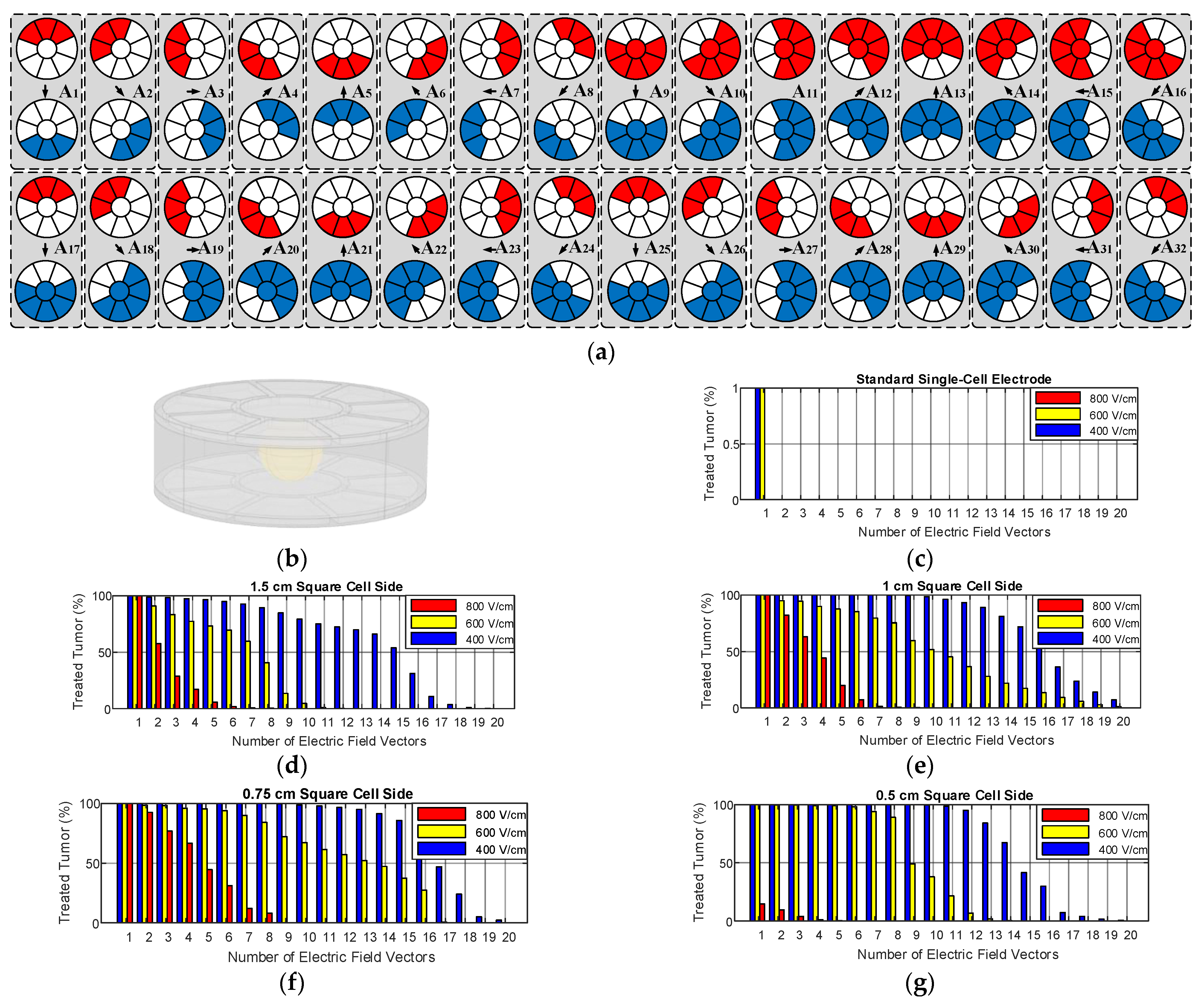
3.2. Size and Geometry Optimization

The MPPE prototypes are designed to apply the electric field in the best possible way. One of the advantages of this electrode is that its geometry can be varied and optimized for each case. In this section, a theorical example has been proposed with a spherical tumor of 0.75 mm in diameter placed in the center of a healthy tissue without imperfection, 1 cm thick. The objective is to present a method that allows optimizing the geometry of the electrode based on an initial study of the geometry of the tumor and its positioning. In order to evaluate both geometries, the treated volumes have been estimated in the two models, varying the surface of the electrodes and with an equivalent electrode surface ( L E = π R E and L I = π R I ). To vary the surface of the electrodes, only the side of the electrode cell of the square electrodes has been varied and then a circular electrode with the same surfaces has been constructed. The data have been analyzed assuming electroporation limit values of 800, 600 and 400 V/cm and an angle between 30° and 150°. In the simulation, 32 different configurations of the electrodes have been applied. There are more CSs that may be useful in other cases in which the tumor is positioned differently, or the electrodes are not positioned evenly. For the example that has been used, the 32 proposed CSs have been studied individually (Figure 11a and Figure 12b). The CSs used are considered to apply a uniform electric field and do not produce many edge effects.
Figure 11a shows the configurations applied to the square electrode, in Figure 12b shows the configurations applied to the circular electrode and in Figure 11b and Figure 12b their results can be seen. It shows the data obtained from the comparison of the proposed electrodes. Firstly, both electrodes allow to treat a large all tumor in 10 directions at 400 V/cm as minimum [27]. It is also possible to cover an important part of the volume in 16 directions. In this example, the optimal geometry within those studied would be the circular electrode with the surface of the square electrode 0.75 mm on a side. In both geometries the best results have been obtained with the same size of central electrode cell. This is because the ideal electrode cell size depends on both the tumor radius and the spacing between the electrodes. Regarding the size of the tumor, the electrode cells must have a comparable size to be able to focus on the treatment. The electrode cells should also have a size comparable to the separation of the electrodes since it has been observed that if the electrode cells are too large, the electric field concentrates on the edges of the electrodes treating the same volume, this separates the outer electrode cells, producing a worse field distribution.
The results make it clear that it is possible to optimize the geometry of the presented electrodes, and that their use allows to obtain a significantly increase of number of directions in which each point of the tissue can be treated, also being able to obtain the advantages of state-of-art electrodes.

4. Conclusions

Electroporation is a cancer treatment technique with promising results that needs to use the latest power electronics technologies and electromagnetic designs. To achieve effective treatments, an adequate electric field distribution application, one interesting way is the use of advanced multi-electrode proposals and multi-output power converters.
The proposed structure allows the application of a uniform electric field like the current flat plates but also allows the application of several electric field vectors with different orientations. Applying electric field vectors in different orientations can improve the homogeneity an the efficacy of the treatment [33,34,35] as is done with needle multi-electrodes [23,24,25,36,37], but unlike these the proposed electrode does not need to be repositioned. Although the use of flat plate electrodes is not very common in internal tissues, some experiments have been carried out, and it is believed that with a suitable support the proposed multi-electrodes could be better in some cases.
From the obtained results, it can be concluded that it is possible to improve the treatment by means of the proposed multi-electrodes, but their dimensions and design must be adapted in order to optimize the application for each tumor geometry and position. Unlike traditional needle electrodes, the proposed methodology reduces the edge effect in the electric field strength distribution, minimizes thermal effects, and reduces injuries that can occur due to electrode repositioning.
The proposed multi-electrode is an alternative to the current parallel-plates, but it allows applying the electric field in a more flexible way to improve the homogenization of the treatments. It is therefore useful in the treatment of large tumors located in areas accessible without surgery, or even in the treatment of internal organs with high blood perfusion where needles cannot be used.
The proposed electrodes could be useful in the treatment of liver tumors where metastases are common. In this area, electroporation has great advantages since it is not affected by the vascularization of the liver, and also the liver has been documented to be able to regenerate from the effects of electroporation [5], since the electric field does not affect vascular scaffold. Therefore, the proposed methodology could treat large volumes of liver with metastases in a fast and effective way, allowing the regeneration of healthy tissue. Finally, although parallel plates are often difficult to apply because they are usually applied by tweezers, the proposed electrodes can be built with flexible PCBs and could be applied in an easier way avoiding the use of tweezers.
To test the proposed electrodes, a new multi-output generator has been developed. The proposed structures have been analyzed and compared, and finite element analysis models have been developed and validated.

Author Contributions

Conceptualization, B.L.-A., H.S. and O.L.; methodology, B.L.-A., H.S. and O.L.; validation, B.L.-A. and P.B.; formal analysis, B.L.-A.; investigation, B.L.-A., H.S., O.L. and P.B.; writing—original draft preparation, B.L.-A.; writing—review and editing, O.L., H.S., P.B. and J.M.B. All authors have read and agreed to the published version of the manuscript.

Funding

This work was partly supported by the Spanish MICINN and AEI under Project PID2019-103939RB-I00, co-funded by EU through FEDER program, and by the MECD under grant FPU16/03765.

Conflicts of Interest

The authors declare no conflict of interest.

References

  1. Junquera, M.C.; Castiella, T.; Gracia-Llanes, J.; López-Alonso, B.; Hernáez, A.; García-Hernández, L.; Güemes, A.; Mejía, E.; Iruzubieta, P.; Naval, A.; et al. Electron microscope evaluation of irreversible electroporation on the liver in a porcine model. Histol. Histopathol. 2017, 32, 125. [Google Scholar]
  2. Weaver, J.C. Electroporation of cells and tissues. IEEE Trans. Plasma Sci. 2000, 28, 24–33. [Google Scholar] [CrossRef] [Green Version]
  3. Lopez-Alonso, B.; Hernaez, A.; Sarnago, H.; Naval, A.; Guemes, A.; Junquera, C.; Burdio, J.M.; Castiella, T.; Monleon, E.; Gracia-Llanes, J.; et al. Histopathological and Ultrastructural Changes after Electroporation in Pig Liver Using Parallel-Plate Electrodes and High-Performance Generator. Sci. Rep. 2019, 9, 12. [Google Scholar] [CrossRef] [PubMed]
  4. Monleón, E.; Castiella, T.; Mejía, E.; Gracia-Llanes, J.; Iruzubieta, P.; Junquera, M.C.; Hernáez, A.; Güemes, A.; López-Alonso, B.; Sarnago, H.; et al. Remodelling of liver tissue after irreversible electroporation in porcine. Histol. Histopathol. 2019, 34, 132. [Google Scholar]
  5. Iruzubieta, P.; Gracia-Llanes, J.; Meleón, E.; Mejía, E.; Castiella, T.; Hernáez, A.; Güemes, A.; López-Alonso, B.; Sarnago, H.; Lucía, O.; et al. Ultrastructural study of pig liver regeneration following ablation with irreversible electroporation. Histol. Histopathol. 2019, 34, 131. [Google Scholar]
  6. Geboers, B.; Scheffer, H.J.; Graybill, P.M.; Ruarus, A.H.; Nieuwenhuizen, S.; Puijk, R.S.; Tol, P.M.; Davalos, R.V.; Rubinsky, B.; Gruijl, T.D.; et al. High-Voltage Electrical Pulses in Oncology: Irreversible Electroporation, Electrochemotherapy, Gene Electrotransfer, Electrofusion, and Electroimmunotherapy. Radiology 2020, 295, 254–272. [Google Scholar] [CrossRef]
  7. Yarmush, M.L.; Golberg, A.; Sersa, G.; Kotnik, T.; Miklavcic, D. Electroporation-Based Technologies for Medicine: Principles, Applications, and Challenges. In Annual Review of Biomedical Engineering; Annual Reviews; Yarmush, M.L., Ed.; Palo Alto: Santa Clara, CA, USA, 2014; Volume 16, pp. 295–320. [Google Scholar]
  8. O’Brien, T.; Passeri, M.; Lorenzo, M.; Sulzer, J.; Lyman, W.; Swet, J.; Vrochides, D.; Baker, E.; Iannitti, D.; Davalos, R.; et al. Experimental High-Frequency Irreversible Electroporation Using a Single-Needle Delivery Approach for Nonthermal Pancreatic Ablation In Vivo. J. Vasc. Interv. Radiol. 2019, 30, 854–862.e7. [Google Scholar] [CrossRef]
  9. Zhang, Y.; Lyu, C.; Liu, Y.; Lv, Y.; Chang, T.T.; Rubinsky, B. Molecular and histological study on the effects of non-thermal irreversible electroporation on the liver. Biochem. Biophys. Res. Commun. 2018, 500, 665–670. [Google Scholar] [CrossRef] [PubMed]
  10. Mathy, R.M.; Tinoush, P.; da Florencia, R.D.; Braun, A.; Ghamarnejad, O.; Radeleff, B.; Kauczor, H.-U.; Chang, D.-H. Impact of needle positioning on ablation success of irreversible electroporation: A unicentric retrospective analysis. Sci. Rep. 2020, 10, 21902. [Google Scholar] [CrossRef] [PubMed]
  11. Huang, D.; Zhao, D.; Li, J.; Du, L.; Wei, Z.; Liang, Z.; Li, Z. In A minimally invasive in vivo electroporation method utilizing flexile electrode and microneedle roller. In Proceedings of the 2017 19th International Conference on Solid-State Sensors, Actuators and Microsystems (TRANSDUCERS), Kaohsiung City, Taiwan, 18–22 June 2017; pp. 1684–1687. [Google Scholar]
  12. Neal, R.E., 2nd; Singh, R.; Hatcher, H.C.; Kock, N.D.; Torti, S.V.; Davalos, R.V. Treatment of breast cancer through the application of irreversible electroporation using a novel minimally invasive single needle electrode. Breast Cancer Res. Treat. 2010, 123, 295–301. [Google Scholar] [CrossRef] [Green Version]
  13. Berkenbrock, J.A.; Machado, R.G.; Suzuki, D.O.H. Electrochemotherapy Effectiveness Loss due to Electric Field Indentation between Needle Electrodes: A Numerical Study. J. Healthc. Eng. 2018, 2018, 6024635. [Google Scholar] [CrossRef]
  14. Davalos, R.V.; Garcia, P.A.; Edd, J.F. Thermal Aspects of Irreversible Electroporation. In Irreversible Electroporation; Rubinsky, B., Ed.; Springer: Berlin/Heidelberg, Germany, 2010; pp. 123–154. [Google Scholar]
  15. Biasiolo, L.; Bariani, P.; Marchi, N.; Dughiero, F.; Sieni, E.; Campana, L. An Electrode for the Treatment of Large Surfaces in ECT. In Proceedings of the IECON 2018 44th Annual Conference of the IEEE Industrial Electronics Society, Washington, DC, USA, 21–23 October 2018; pp. 3319–3323. [Google Scholar]
  16. Hansen, H.; Bourke, M.; Stigaard, T.; Clover, A.; Buckley, M.; O’Riordain, M.; Winter, D.; Johannesen, H.; Hansen, R.; Heebøll, H.; et al. Electrochemotherapy for colorectal cancer using endoscopic electroporation: A phase 1 clinical study. Endosc. Int. Open 2020, 8, E124–E132. [Google Scholar]
  17. Rombouts, S.J.E.; van Dijck, W.P.M.; Nijkamp, M.W.; Derksen, T.C.; Brosens, L.A.A.; Hoogwater, F.J.H.; van Leeuwen, M.S.; Borel Rinkes, I.H.M.; van Hillegersberg, R.; Wittkampf, F.H.; et al. Clinical and pathological outcomes after irreversible electroporation of the pancreas using two parallel plate electrodes: A porcine model. Hpb Off. J. Int. Hepato Pancreato Biliary Assoc. 2017, 19, 1058–1065. [Google Scholar] [CrossRef] [Green Version]
  18. Panella, C.; Castellvi, Q.; Moll, X.; Quesada, R.; Villanueva, A.; Iglesias, M.; Naranjo, D.; Sanchez-Velazquez, P.; Andaluz, A.; Grande, L.; et al. Focused transhepatic electroporation mediated by hypersaline infusion through the portal vein in rat model. Preliminary results on differential conductivity. Radiol. Oncol. 2017, 51, 415–421. [Google Scholar] [CrossRef] [PubMed] [Green Version]
  19. Denzi, A.; Strigari, L.; Di Filippo, F.; Botti, C.; Di Filippo, S.; Perracchio, L.; Ronchetti, M.; Cadossi, R.; Liberti, M. Modeling the positioning of single needle electrodes for the treatment of breast cancer in a clinical case. Biomed. Eng. Online 2015, 14, S1. [Google Scholar] [CrossRef] [PubMed] [Green Version]
  20. Cvetkoska, A.; Pirc, E.; Rebersek, M.; Magjarevic, R.; Miklavcic, D. Towards standardization of electroporation devices and protocols. IEEE Instrum. Meas. Mag. 2020, 23, 74–81. [Google Scholar] [CrossRef]
  21. Bernardis, A.; Bullo, M.; Campana, L.G.; Barba, P.D.; Dughiero, F.; Forzan, M.; Mognaschi, M.E.; Sgarbossa, P.; Sieni, E. Electric field computation and measurements in the electroporation of inhomogeneous samples %. J. Open Phys. 2017, 15, 790–796. [Google Scholar] [CrossRef]
  22. Pavliha, D.; Kos, B.; Marcan, M.; Zupanic, A.; Sersa, G.; Miklavcic, D. Planning of Electroporation-Based Treatments Using Web-Based Treatment-Planning Software. J. Membr. Biol. 2013, 246, 833–842. [Google Scholar] [CrossRef] [Green Version]
  23. Campana, L.G.; Bullo, M.; Di Barba, P.; Dughiero, F.; Forzan, M.; Mognaschi, M.E.; Sgarbossa, P.; Tosi, A.L.; Bernardis, A.; Sieni, E. Effect of Tissue Inhomogeneity in Soft Tissue Sarcomas: From Real Cases to Numerical and Experimental Models. Technol. Cancer Res. Treat. 2018, 17, 1533033818789693. [Google Scholar] [CrossRef] [PubMed] [Green Version]
  24. Castiello, M.; Dughiero, F.; Scandola, F.; Sieni, E.; Campana, L.; Rossi, C.; Mattei, M.; Pellati, A.; Ongaro, A. A New Grid Electrode for Electrochemotherapy Treatment of Large Skin Tumors. Dielectr. Electr. Insul. IEEE Trans. 2014, 21, 1424–1432. [Google Scholar] [CrossRef]
  25. Ongaro, A.; Campana, L.; Mattei, M.; Dughiero, F.; Forzan, M.; Pellati, A.; Rossi, C.; Sieni, E. Evaluation of the Electroporation Efficiency of a Grid Electrode for Electrochemotherapy: From Numerical Model to In Vitro Tests. Technol. Cancer Res. Treat. 2015, 15, 296–307. [Google Scholar] [CrossRef]
  26. López-Alonso, B.; Sarnago, H.; Burdío, J.M.; Lucía, Ó. In Multi-Electrode Architecture Analysis and Modeling for Cancer Treatment using Electroporation. In Proceedings of the IECON 2020 The 46th Annual Conference of the IEEE Industrial Electronics Society, Singapore, 18–21 October 2020; pp. 718–723. [Google Scholar]
  27. López-Alonso, B.; Sarnago, H.; Lucía, O.; Briz, P.; Burdío, J.M. Real-Time Impedance Monitoring During Electroporation Processes in Vegetal Tissue Using a High-Performance Generator. Sensors 2020, 20, 3158. [Google Scholar] [CrossRef] [PubMed]
  28. López-Alonso, B.; Sarnago, H.; Burdío, J.M.; Lucía, O. Electro-thermal modeling of irreversible electroporation and validation method of electric field distribution. Int. J. Appl. Electromagn. Mech. 2020, 63, 41–50. [Google Scholar] [CrossRef]
  29. Corovic, S.; Lackovic, I.; Sustaric, P.; Sustar, T.; Rodic, T.; Miklavcic, D. Modeling of electric field distribution in tissues during electroporation. Biomed. Eng. Online 2013, 12, 16. [Google Scholar] [CrossRef] [Green Version]
  30. Breton, M.; Buret, F.; Krähenbühl, L.; Leguèbe, M.; Mir, L.; Perrussel, R.; Poignard, C.; Scorretti, R.; Voyer, D. Non-Linear Steady-State Electrical Current Modeling for the Electropermeabilization of Biological Tissue. IEEE Trans. Magn. 2015, 51, 1–4. [Google Scholar] [CrossRef] [Green Version]
  31. López-Alonso, B.; Sarnago, H.; Lucía, O.; Burdío, J.M. In Multiple-Output Generator for Omnidirectional Electroporation and Real-Time Process Monitoring. In Proceedings of the 2021 IEEE Applied Power Electronics Conference and Exposition (APEC21), Phenix, AZ, USA, 9–12 June 2021. [Google Scholar]
  32. Castellví, Q.; Banús, J.; Ivorra, A. 3D Assessment of Irreversible Electroporation Treatments in Vegetal Models. In 1st World Congress on Electroporation and Pulsed Electric Fields in Biology, Medicine and Food & Environmental Technologies; Jarm, T., Kramar, P., Eds.; Springer: Singapore, 2016; pp. 294–297. [Google Scholar]
  33. Valic, B.; Golzio, M.; Pavlin, M.; Schatz, A.; Faurie, C.; Gabriel, B.; Teissié, J.; Rols, M.P.; Miklavcic, D. Effect of electric field induced transmembrane potential on spheroidal cells: Theory and experiment. Eur. Biophys. J. 2003, 32, 519–528. [Google Scholar] [CrossRef]
  34. Reberšek, M.; Faurie, C.; Kandušer, M.; Čorović, S.; Teissié, J.; Rols, M.-P.; Miklavčič, D. Electroporator with automatic change of electric field direction improves gene electrotransfer in-vitro. Biomed. Eng. Online 2007, 6, 25. [Google Scholar] [CrossRef] [Green Version]
  35. Čorović, S.; Županič, A.; Kranjc, S.; Al Sakere, B.; Leroy-Willig, A.; Mir, L.M.; Miklavčič, D. The influence of skeletal muscle anisotropy on electroporation: In vivo study and numerical modeling. Med. Biol. Eng. Comput. 2010, 48, 637–648. [Google Scholar] [CrossRef] [PubMed] [Green Version]
  36. Leticia Vera-Tizatl, A.; Elizabeth Vera-Tizatl, C.; Vera-Hernandez, A.; Leija-Salas, L.; Rodriguez, S.; Miklavcic, D.; Kos, B. Computational Feasibility Analysis of Electrochemotherapy with Novel Needle-Electrode Arrays for the Treatment of Invasive Breast Ductal Carcinoma. Technol. Cancer Res. Treat. 2018, 17, 1533033818794939. [Google Scholar] [CrossRef]
  37. Brock, R.M.; Beitel-White, N.; Davalos, R.V.; Allen, I.C. Starting a Fire Without Flame: The Induction of Cell Death and Inflammation in Electroporation-Based Tumor Ablation Strategies. Front. Oncol. 2020, 10, 1235. [Google Scholar] [CrossRef]
Figure 1. Reversible (RE) and irreversible (IRE) electroporation of an animal cell.
Energies 14 01892 g001
Figure 2. State-of-the-art electroporation electrodes applied to human liver tissue: Needle (a) and parallel-plate (e) electrodes. Finite element modeling of electroporation: Needle (b) and parallel-plate (f) electrodes. Electric field modulus in horizontal slice (z = 0): Needle (c) and parallel-plate (g) model. Electric field modulus in vertical slice (y = 0): Needle (d) and parallel-plate (h) model.
Energies 14 01892 g002
Figure 3. Proposed multi-electrode geometries: (a) squared electrode and (b) circular electrode.
Energies 14 01892 g003
Figure 4. Schematic of the application of voltage in example setting: (a) Electric field vectors in the circular model applying 32 voltage settings; (b) in vertical slice (y = 0); (c) in horizontal slice (z = 0).
Energies 14 01892 g004
Figure 5. Proposed multi-electrode models meshing: (a) squared electrode model, (e) circular electrode model. Cell settings (CS)where the voltage is applied: (b) squared electrode, (f) circular electrode. Module and direction of the electric field in vertical slice (y = 0): (c) squared electrode, (g) circular electrode. Module and direction of the electric field in horizontal slice (z = 0): (d) squared electrode and (h) circular electrode.
Energies 14 01892 g005
Figure 6. Electrical conductivity of the simulated tissue, as a function of the electric field applied at 10 kHz [21,27].
Energies 14 01892 g006
Figure 7. Example of evaluation of independent electric field vectors: (a) angle between the electric field vectors produced by red CS and configuration yellow CS, (b) angle between the electric field vectors produced by blue CS and configuration yellow CS, (c) angle between the electric field vectors produced by blue CS and configuration red CS and (d) evaluation of independent electric field vectors in each point of the mesh.
Energies 14 01892 g007
Figure 8. Image of setup used in the experiment.
Energies 14 01892 g008
Figure 9. Results of the application in plant tissue of a single CS: (a) applied CS, (b) photo of the dyed potato and simulated electric field, using circular electrode, (c) photo of the degraded potato and simulated electric field, using circular electrode, (d) photo of the dyed potato and simulated electric field, using square electrode, and (e) photo of the degraded potato and simulated electric field, using square electrode.
Energies 14 01892 g009
Figure 10. Result of the application in plant tissue of 8 CSs: (a) applied CSs, (b) photo of the dyed potato and simulated maximum electric field at each point, using circular electrode, (c) photo of the degraded potato and simulated maximum electric field at each point, using circular electrode, (d) photo of the dyed potato and simulated electric field, using square electrode, and (e) photo of the degraded potato and simulated electric field, using square electrode.
Energies 14 01892 g010
Figure 11. Square electrode optimization results: (a) 32 CSs applied, and (b) geometry of the square matrix parallel-plate electrode (MPPE) with tumor. Bar graphs with the percentage of tumor treated: standard electrode (c), 1.5 cm square electrode cell side (d), 1 cm square electrode cell side (e), 0.75 cm square electrode cell side (f) and 0.5 cm square electrode cell side (g).
Energies 14 01892 g011
Figure 12. Circular electrode optimization results: (a) 32 CSs applied, and (b) geometry of the circular MPPE with tumor. Bar graphs with the percentage of tumor treated: standard electrode (c), 1.5 cm square electrode cell side (d), 1 cm square electrode cell side (e), 0.75 cm square electrode cell side (f) and 0.5 cm square electrode cell side (g).
Energies 14 01892 g012
Table 1. Model parameters extracted from [27,28].
SymbolParameterValue (Unit)
σiInsulating Electrical Conductivity0.0001 (S/m)
σsSteel Electrical Conductivity300000 (S/m)
σf_hFinal Healthy Electrical Conductivity0.4 (S/m)
σ0_hInitial Healthy Electrical Conductivity0.03 (S/m)
Kv_hHealthy Slope Constant0.01
Eth_hHealthy Electric Field Threshold 300 (V/cm)
σf_tFinal Tumor Electrical Conductivity1.2 (S/m)
σ0_tInitial Tumor Electrical Conductivity0.09 (S/m)
Kv_tTumor Slope Constant0.01
Eth_tTumor Electric Field Threshold300 (V/cm)
Publisher’s Note: MDPI stays neutral with regard to jurisdictional claims in published maps and institutional affiliations.

