Article

Modulation Variants in DC Circuits of Power Rectifier Systems with Improved Quality of Energy Conversion—Part I

by
Tomasz Pajchrowski
*,
Michał Krystkowiak
and
Dominik Matecki
Robotics and Electrical Engineering, Faculty of Control, Poznan University of Technology, 60-965 Poznań, Poland
*
Author to whom correspondence should be addressed.
Energies 2021, 14(7), 1876; https://doi.org/10.3390/en14071876
Submission received: 18 February 2021 / Revised: 23 March 2021 / Accepted: 25 March 2021 / Published: 29 March 2021
(This article belongs to the Special Issue Modern Electrical Drives: Trends, Problems, and Challenges)

Abstract

:
The article presents various concepts of three-phase power rectifiers with improved quality of converted electric power. This effect is obtained by modulating the currents in the DC output circuits of the rectifiers by means of power electronics controlled voltage or current sources, working as a so-called voltage or current modulators. For further quality improvement of the grid currents of the analyzed systems, it was proposed to use an additional controlled current source connected in parallel to the DC load, hereinafter referred to as a supporting system. The original elaborated method of controlling this source (supporting system) was presented. The main goal of the work was to propose a solution for an effective method of improving the quality of energy conversion in rectifier systems, especially high power ones, by using controlled current sources in DC circuits, operating as the power electronics current modulator and the supporting system.

Graphical Abstract

1. Introduction

Rectifiers are power electronics devices that convert AC energy into DC energy. They are widely used in many branches of industry, e.g., in rail transport, metallurgy and mining. They also play an important role in energy transmission and processing. They should be characterized by, inter alia, high reliability and simple structure (reduction of investment costs), while ensuring high quality of energy conversion.
Unfortunately, commonly used, classic rectifier circuits draw higher harmonics of the current from the power grid. It is especially visible in the rectifiers with a small number of rectified pulses p . Therefore, efforts are being made to increase the number of pulses by using n component rectifiers connected in series or in parallel. It is common practice to use three-phase converters with the number of pulses p j , as the component rectifiers. Thanks to their appropriate connection, it is possible to obtain a complex rectifier with the total number of pulses p = n p j . These can be, for example, 12-pulse systems that allow the elimination of the 5th and 7th harmonics of the current [1,2,3]. Nevertheless, they are still characterized by a significant distortion of the current drawn from the grid, especially at the low short-circuit power of the grid [4,5,6].
The solution of this problem is the use of appropriate filters, both passive and active (acting as active compensators) and combinations of both solutions [7,8,9,10]. Higher harmonics of the current drawn by the rectifiers can also be limited by the pulse width modulation algorithms in the input circuits, using fully controlled transistor rectifiers. However, it is associated with, among others, high commutation losses and electromagnetic disturbances [11]. The described methods are relatively expensive and require complex high-current, measurement and control structures. For this reason, a very attractive way to improve the quality of energy conversion is to use modulation in the rectifier output circuits. For this purpose, a controlled voltage or current source with given parameters should be used in parallel or in series with the load. It should be noted that the solution based on the current source (current modulator) is more effective, which results in, e.g., high efficiency, high reliability and effective elimination of undesirable harmonics in grid currents. A great advantage is also the possibility of using the current modulator in systems already operating without need of significant modifications, which contributes to cost minimization.
The first part of the article concerns the improvement of the quality of grid currents in complex rectifier systems with the use of the voltage modulator. In the following chapters, the authors deal with the issue of improving the quality of converted energy as a result of applying the solution based on the current modulator, which is the main subject of the research. The general concept and principle of operation of the system was described, including the method of its implementation. In the further part of the article, the use of the supporting system (additional current source) of the main current modulator was proposed. The original method of controlling this source, developed as part of the work, was presented. It allows to achieve grid currents very close to sinusoidal signals, while minimizing reactive power and maintaining the required energy balance of the system. The author’s method for determining the reference signal was described (relevant formulas and block diagrams were presented). As a consequence, an improvement in the quality of converted energy in rectifier systems was achieved.
The results of the presented simulation research were realized with the help of Matlab, Orcad Family Release and Melcosim applications. Also, the selected components of the experimental model are described at the end of the article. In the final chapter, the authors confirm the legitimacy of using the proposed solutions and present the planned further research.

1.1. General Concept of Modulation in the Rectifier Output Circuit

The classic 12-pulse rectifier system, consisting of two parallel-connected three-phase rectifier bridges, supplied with voltages of appropriate phase shifts (as a result of the use of power transformers with different connection groups), is characterized by consumption of the higher harmonics from the power grid. Helpful in their significant reduction is the use of the controlled voltage or current sources in the DC circuit, which act as the voltage and current modulator, respectively [12,13]. By modulating the output currents of component rectifiers, their input currents are shaped, and consequently the resultant grid currents for individual phases. Thus, by setting strictly defined parameters of the voltage or current sources (depending on the modulator type used), the content of higher harmonics of the grid current is influenced. Parallel connection of rectifier bridges in the described solution ensures constant load current.

1.2. Voltage Modulator in a Rectifier System

The use of a controlled voltage source as a voltage modulator in a DC circuit causes an increase in the value of the modulating component of the output currents of each of the bridges of the parallel-connected complex rectifier system. It corresponds to the magnetizing current of the equalizing choke, also called a phase-to-phase transformer. This transformer is necessary due to the differences in the instantaneous values of the output voltages of the component systems.
Both rectifying bridges are supplied from phase voltages shifted relative to each other by the angle of π/6. This shift was determined on the basis of the relationship [14]:
δ = 2 π n p j ,
where n —number of connected component rectifiers, p j —number of pulses of a single component rectifier.
The phase shift between these voltages was obtained thanks to two transformers: one connected in a star-star configuration, the other in a star-delta configuration (it is also possible to use only one transformer with a star-delta connection). The voltage modulator (VM) in the case of the presented simulation model consists of a phase-to-phase transformer, power electronics switches and a rectifying diode. In the physical system, SCR (silicon-controlled rectifier) thyristors can be used instead of ideal switches, connected in series with the diode. Their natural commutation is possible thanks to the voltage induced on the phase-to-phase transformer. A simplified diagram of a model of a rectifier system composed of the voltage modulator in the DC circuit is presented in Figure 1.
If we assume equality of flows in the windings of the phase-to-phase transformer for the conductive switch S3, we obtain Equation (2) (the influence of the magnetizing current has been neglected):
Z D 2 Z X i d 1 ( t ) = Z D 2 + Z X i d 2 ( t ) ,
where i d 1 ( t ) , i d 2 ( t ) —output currents of component rectifiers, Z D —the total number of turns of the phase-to-phase transformer, Z X —number of turns between taps 1–2 or 1–3 of the phase-to-phase transformer.
The output voltage u d ( 36 ) ( t ) of the presented system is described by Equation (3):
u d ( 36 ) ( t ) = u d ( 12 ) ( t ) + a X u D ( t ) ,
where u d ( 12 ) ( t ) —output voltage for a classic 12-pulse system, u D ( t ) —voltage induced in the phase-to-phase transformer, a X = Z X / Z D .
The waveforms of selected signals obtained as a result of simulation tests are shown in Figure 2.
The spectral analyses of the grid currents for the classic rectifier and the rectifier with the voltage modulator obtained as the result of simulation tests (Figure 3) indicated the reduction of 11th and 13th harmonics, specific to 12-pulse systems. Besides the fundamental component, there are 35th and 37th harmonics, which proves the 36-pulse nature of the converter. It is noticeable that the THD coefficients are reduced almost twice in comparison to the system without modulation. This solution, however, causes commutation breakdowns in the supply voltage waveform and is characterized by the low energy efficiency.

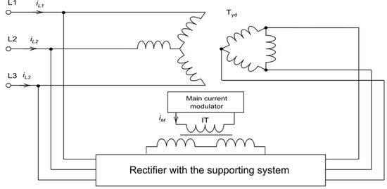
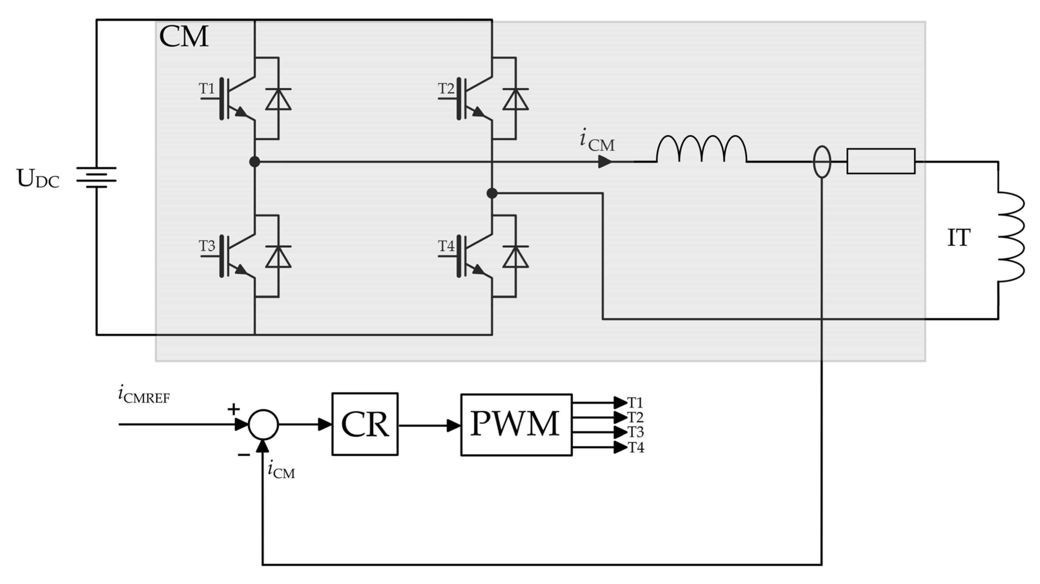
1.3. Current Modulator in the Rectifier Circuit

In the rectifier circuit with output current modulator (CM) the controlled current source coupled to the DC circuit by means of a broadband pulse transformer was used. Also in this case, similarly to the system with voltage modulation, the system can be powered by transformers in the star-star and star-delta configuration (a star-star transformer is not necessary, if there is no need to provide galvanic isolation), ensuring that the phase shift of the respective supply voltages equal π/6. Via the pulse transformer, the modulator’s current is added (taking into account the sign of the current) to the output currents of each of the component rectifiers. Consequently, it becomes possible to shape the input currents of the component bridges, and thus the resultant grid current. The schematic diagram of the rectifier with the current modulator is presented in Figure 4.
With an unsaturated core of the pulse transformer, the equation describing the relationship between the output currents of the component rectifiers and the modulator current has the following form:
N p i d 2 ( t ) i d 1 ( t ) = N s i M ( t ) ,
where i d 1 ( t ) , i d 2 ( t ) —output currents of diode rectifiers, N s , N p —number of turns of a three-winding pulse transformer on the primary and secondary sides, respectively, i M ( t ) —current of the modulator.
Assuming symmetry and no distortion of the grid voltages, it can be assumed, that the rectifier output power P DC is equal to the fundamental harmonic power P L of the currents drawn from the grid (power losses in the system are not taken into account):
3 U L 1 I L 1 = U DC I DC ,
where U L 1 , I L 1 —RMS values of voltage and phase current of the supply source, U DC , I DC —average values of voltage and current in the DC circuit.
If the voltage drops on diodes and reactive-resistive elements are neglected, the average value of the voltage at the rectifier output is equal to:
U DC = 3 6 π U L 1 2 , 34 U L 1 .
Based on Formulas (5) and (6), the fundamental harmonic of the mains current can be described by the relationship:
I L 1 = 6 π 2 I DC sin ( ω L t ) = 2 3 π I DC sin ( ω L t ) 1 , 1 I DC sin ( ω L t ) .
In order to obtain the grid current of a sinusoidal shape, the current modulator should generate a signal described by the formula:
i CM = I DC 2 N 2 3 π I DC sin ω L t i L 1 + 3 i L 2 i L 1 3 i L 2 ,
where ω L = 2 π T L is the frequency of the grid.
However, taking into account a 3-phase electrical system, the current given by (8) should be replaced by a current that has the same phase shift—in respect of a voltage in a given phase. So, the fundamental frequency of the current generated by the modulator should be equal to 6 times that of the grid output voltage frequency ( ω L ). Very close to (8) is the current with, e.g., a triangular shape [15,16,17]. This is given by the following equation:
i CM = 4 π I DC N sin ( 1   6 ω L t ) 1 2 sin ( 3   6 ω L t ) 3 2 + sin ( 5   6 ω L t ) 5 2 ,
The further considerations assume the triangular waveform of the CM current modulator signal. Selected results of the simulation tests are presented in Figure 5 and Figure 6.
The presented simulation results (Figure 5 and Figure 6) were obtained for the current modulator based on an ideal (linear) current source and for the triangular reference signal of the current modulator described by Equation (9). As a consequence, the obtained grid current was very close to the sinusoidal signal (THD = 1.05%). It is also worth noting that the power of the current modulator is only about 2.35% of the load power of the rectifier system, which is a very great advantage of this solution, especially in the case of high-power rectifier systems [16,17].
Subsequent tests were carried out with the use of a simulation model using the current modulator built on the basis of a power electronics controlled current source in the form of a transistor bridge with an inductive low-pass output filter (Figure 7). In this case, a closed-loop control system was used with the negative feedback from the current signal generated by the modulator. The control system uses a unipolar modulation algorithm and a current regulator (CR) (however, the selection of the optimal structure and parameters of the current regulator is not considered in this article).
Selected test results for the described method of implementing the current modulator are shown in Figure 8, Figure 9 and Figure 10, respectively (the operating frequency of the PWM modulator was 10 kHz).
On the basis of the obtained results, it can be stated that the quality of the grid current signals has slightly deteriorated in comparison to the results achieved for the current modulator based on the ideal current source (increase of the THD coefficient from 1.05% to 2.8%). It is a consequence of the imperfections of the applied power electronics current source, in particular:
  • limited current regulator gain in the control circuit (necessity to ensure the stability of the closed-loop control system);
  • limited bandwidth of the system (mainly due to the limitation of dynamics resulting from the need of use the output low-pass filter);
  • delays in the control path of the system (e.g., by the PWM modulator),
  • limited switching frequency of transistors.
It should be noted that there are solutions that increase the dynamics of the current modulator, consequently contributing to the further minimization of the grid current distortions of the considered rectifier system. It is possible, among others, the use of the current source in a multi-channel version [18]. This solution enables, for example: increasing the amplification of the current regulator in the control circuit, while maintaining the stability of the closed-loop system and minimizing the components in the output signal resulting from the frequency of the carrier signal. Another solution may be the use of a tunable choke (reduction of the inductance value in the case of increased requirements for the dynamics of the converter). However, the methods of improving the quality of mapping the reference signal by the current modulator are not discussed in this article. This subject will be discussed in subsequent publications.
The presented signal waveforms and spectral analyses were obtained through simulation tests, assuming the system output power at the level of 6 kW (for supply voltage: 3 × 400 V). This is due to the parameters of the laboratory model, which is under construction. The selected components of this experimental model are described at the end of the article.
However, since the described circuit is dedicated especially to high-power applications, comparative tests were also carried out for the transistor rectifier in the multi-channel version with the system presented in this section. The parameters adopted for both systems are presented in Table 1 and Table 2. The rated output power in case of both systems is about 1500 kW.
The power electronics circuits of the models were built in the MATLAB and, partially, Orcad Family Release environments. Models of the power devices were based on real components, manufactured by Mitsubishi Electric and Cree/Wolfspeed. For power loss calculation in the power modules, MITSUBISHI ELECTRIC supplies software developed by themselves–Melcosim. The latest available version of this environment was also used during research.
The models of the main power devices used in both systems were based on the following parts:
  • RM1800HE-34S: 1700 V/1800 A–a diode module manufactured by Mitsubishi Electric used in diode rectifiers;
  • CM1800DY-34S: 1700 V/1800 IGBT–a module manufactured by Mitsubishi Electric used in transistor rectifier in 3-channel version;
  • CAS120M12BM2: 1200 V/193 A–a SiC MOSFET module manufactured by Cree used in current modulator module.
The calculated curves of the simulation models’ efficiency vs. the relative system’s output power for both elaborated models—for the diode rectifier with current modulator ( η MSN ) and the transistor rectifier in 3-channel version ( η MSS ) are shown in Figure 11.
The research has shown that the efficiency of the power electronics circuits of the diode rectifier with current modulator is about 97.6~97.9% and is about 0.5~1.9% higher, compared to a system equipped with a transistor rectifier.

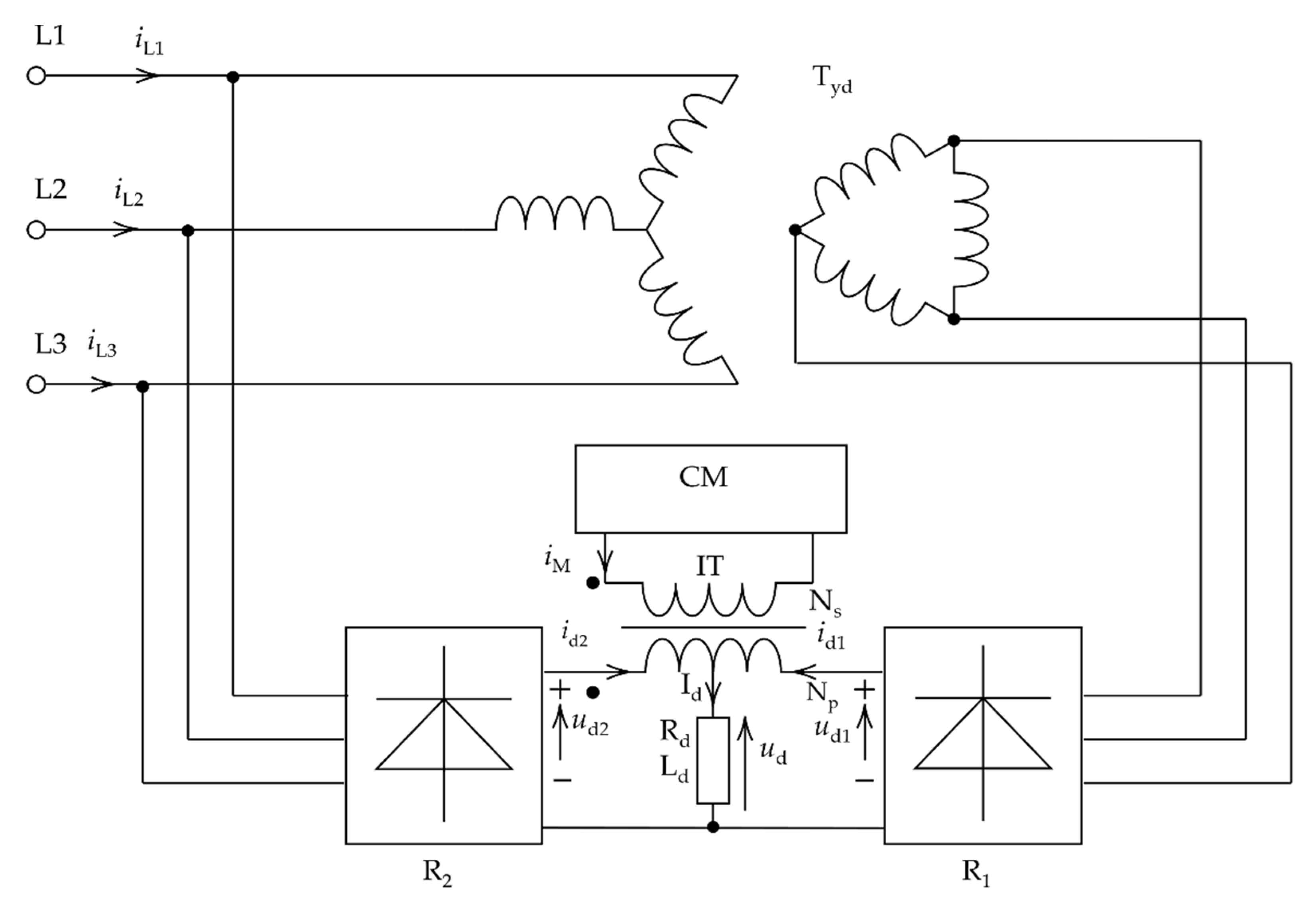
2. Rectifier Circuit with Current Modulator and Additional Supporting System

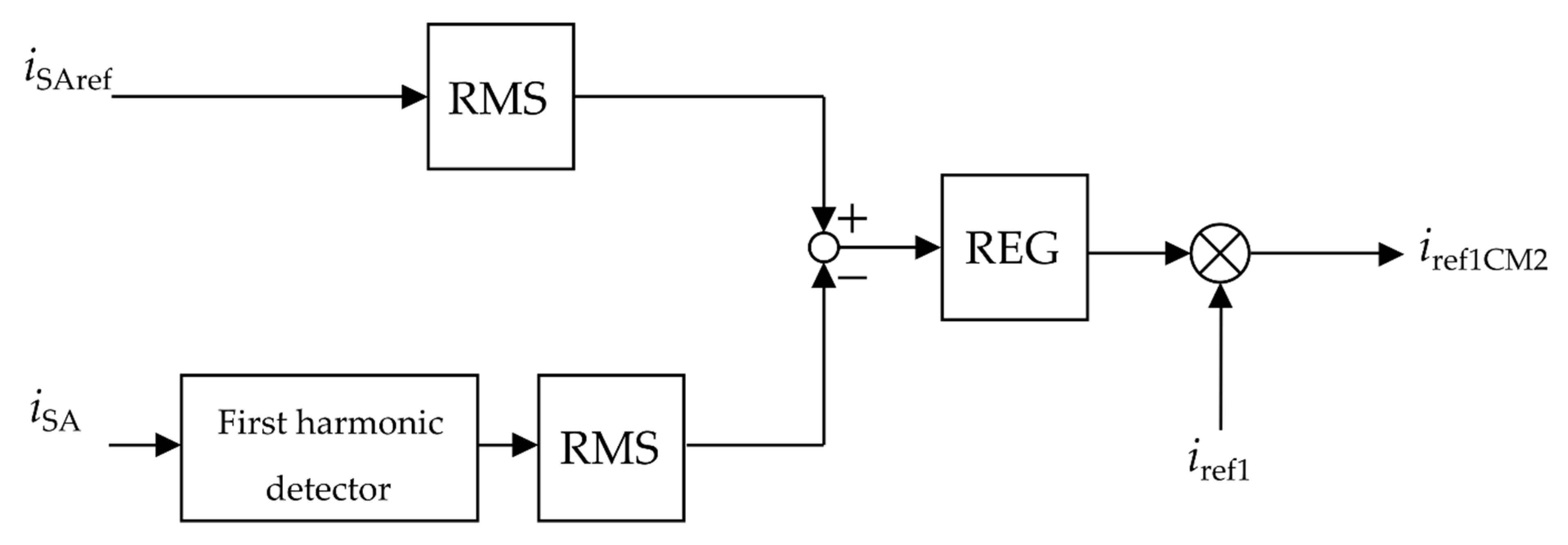
2.1. The Idea of Operation and the Control Algorithm of the Supporting System

The presented solutions based on the current modulator have a positive effect on the waveforms of currents drawn by the diode rectifier from the grid. In this chapter, a solution will be proposed to further improve the quality of grid signals, assuming the use of the current modulator and an additional, controlled current source connected in parallel with the receiver, hereinafter referred to as the supporting system (CM2) [19]. The additional circuit does not affect the load in terms of the value and shape of the voltage and current. However, its use allows further improvement of the quality of currents drawn from the grid as a result of modulating the shape of the output currents of the rectifier components. A schematic diagram of the high-current circuit is shown in Figure 12.
When developing the original method of determining the shape of the reference signal of the supporting system, it was assumed that the grid currents of the rectifier should be as close as possible to the sinusoidal waveforms. Therefore, in the first place, the difference between sinusoidal signals, which are the reference signals of the grid currents for each phase (their amplitudes result from the power demand of the load and losses in the rectifier system) and the grid currents drawn by the rectifier with an active current modulator CM, was determined (the supporting system was deactivated at that time). As a consequence, control errors for each phases were obtained. However, since the operation of the additional supporting system takes place on the DC side and we use it to affect all supply phases, the absolute values of the sum of individual current errors were determined, and then the arithmetic mean value was calculated taking into account the number of phases. In this way, the shape of the reference signal of the supporting system was achieved and it is described by Equation (10):
i ref 1 = i SAref i SA | + | i SBref i SB | + | i SCref i SC 3 ,
where: i SAref —reference current of phase A, i SA —current of phase A with active CM module, i SBref —reference current of phase B, i SB —current of phase B with active CM module, i SCref —reference current of phase C, i SC —current of phase C with active CM module.
The elaborated during research block diagram of the original algorithm is presented in Figure 13. The ABS block represents the system for determining the absolute value of the signal, and the 1/3 block is responsible for determining the arithmetic mean value.
However, the described algorithm does not enable the determination of the amplitude of the reference signal of the supporting system. For this purpose, the system presented on the block diagram in Figure 14 was used.
In this system, the RMS values (RMS blocks) of the reference signal of the sinusoidal grid current and the first harmonic of the grid current of the rectifier system with active modules of the current modulator CM and the supporting system CM2 support system (for the selected phase) are determined. Then, on the basis of the received error, the regulator (REG) determines the amplitude of the reference signal of the supporting system (at this stage of the research, PI structure of the regulator was used). As a final result, after multiplication of the signal i ref 1 and the output signal of the REG regulator, the reference signal of the CM2 supporting system was obtained.
During the development of the described method of determining the reference signal of the supporting system, the symmetry of the power grid was assumed, which is a certain limitation of the method.

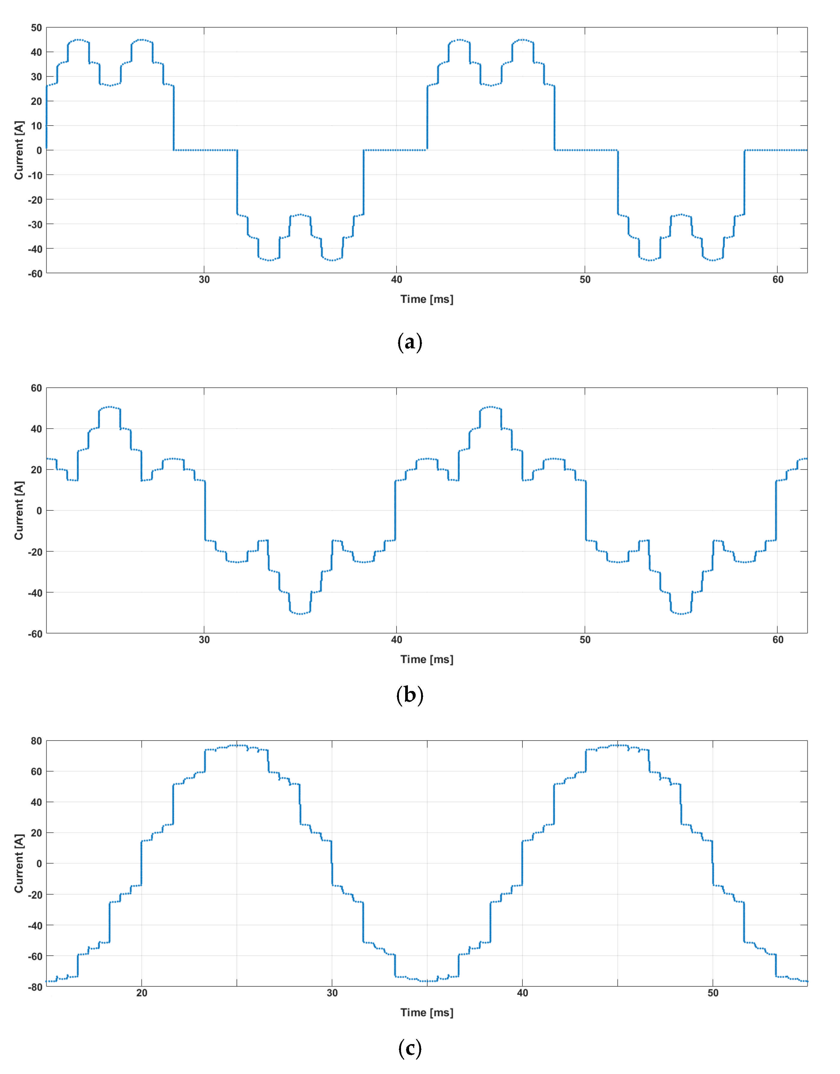
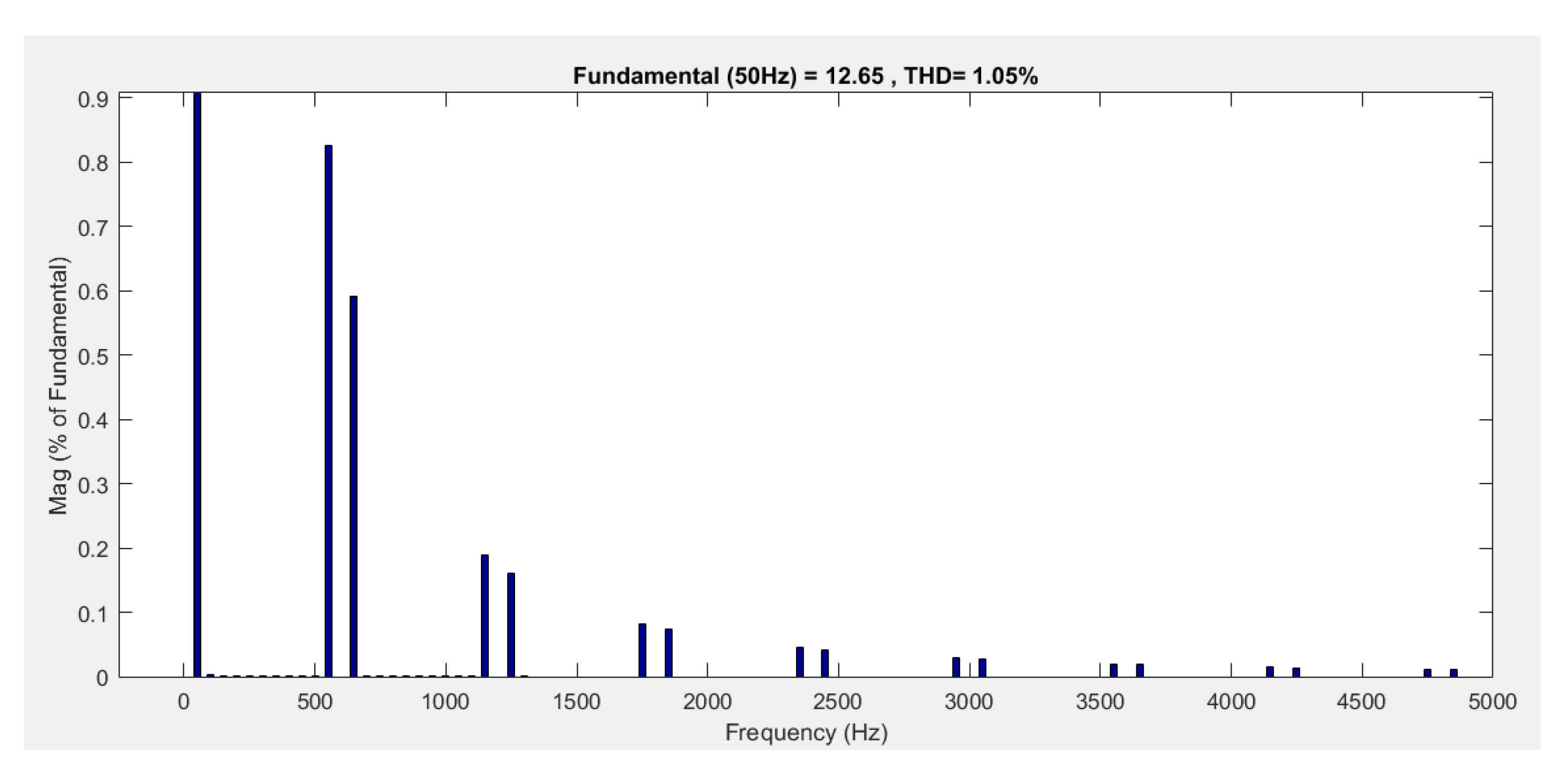
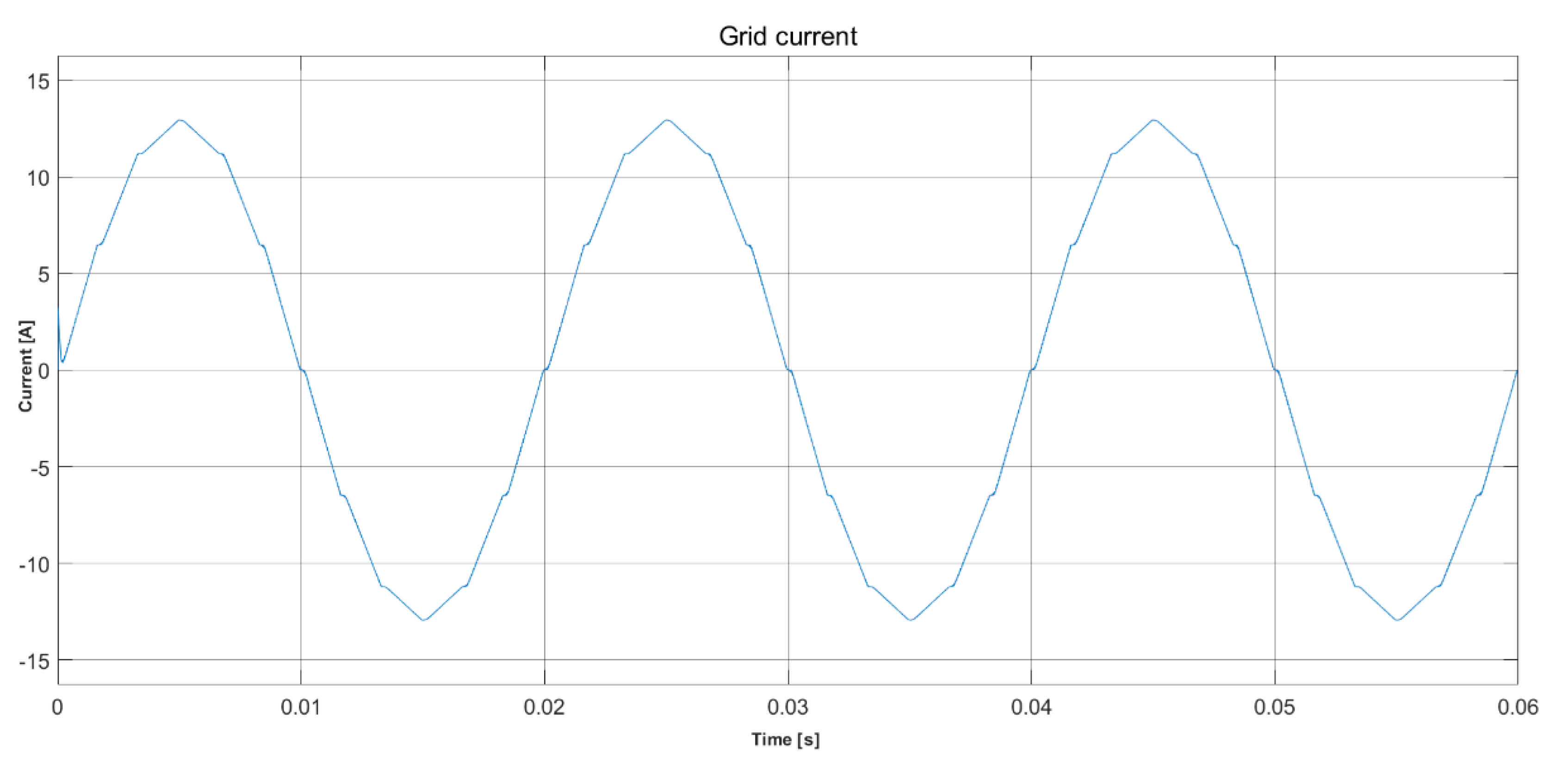
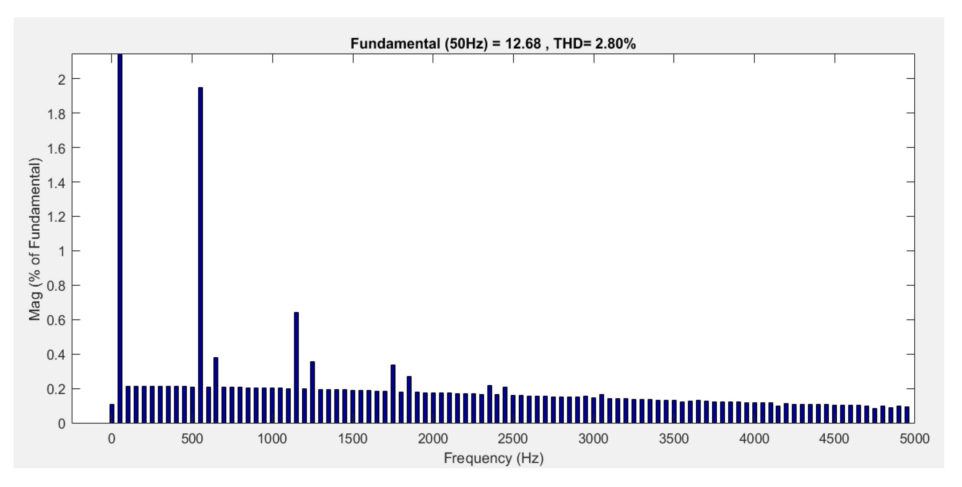
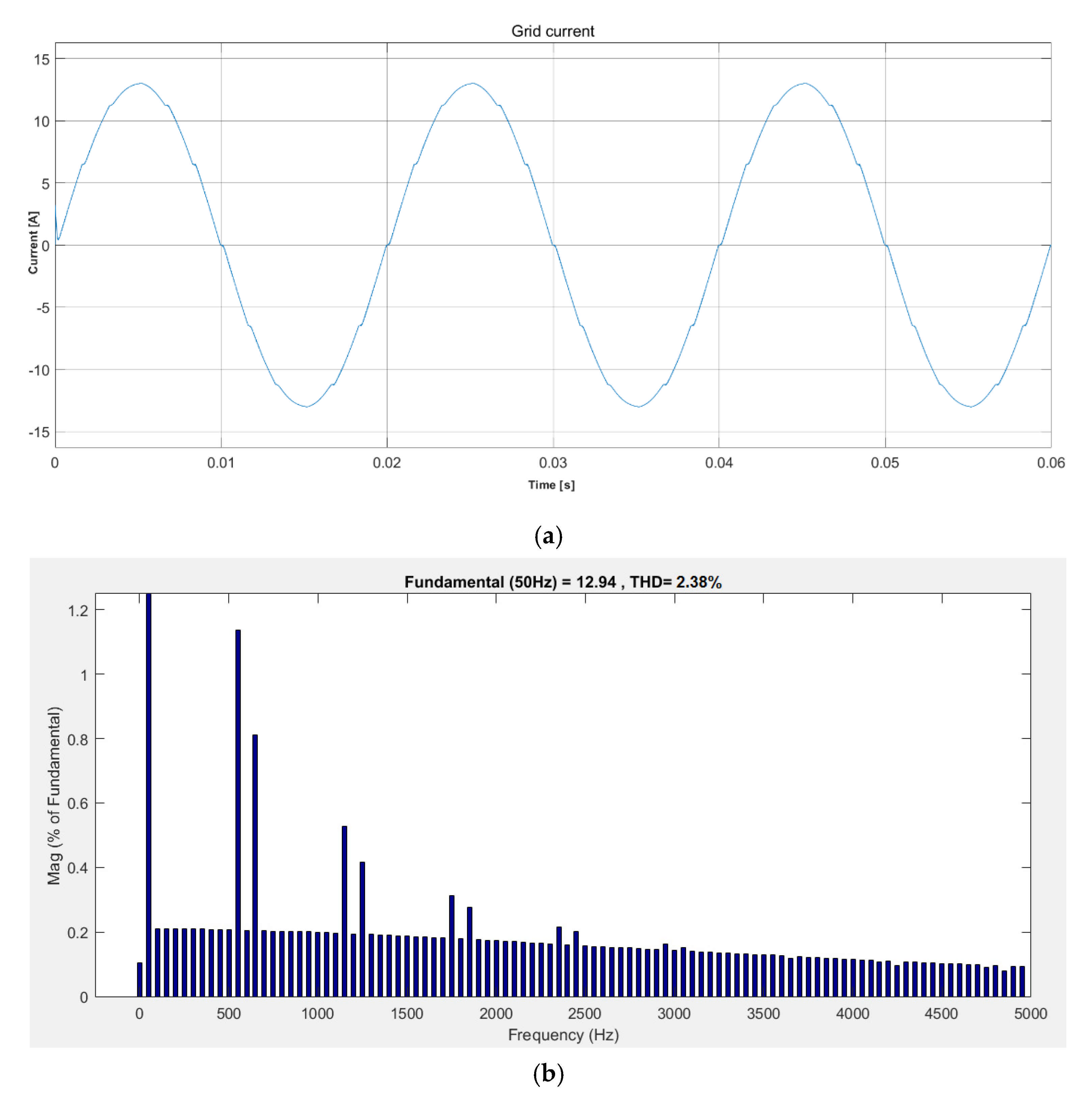
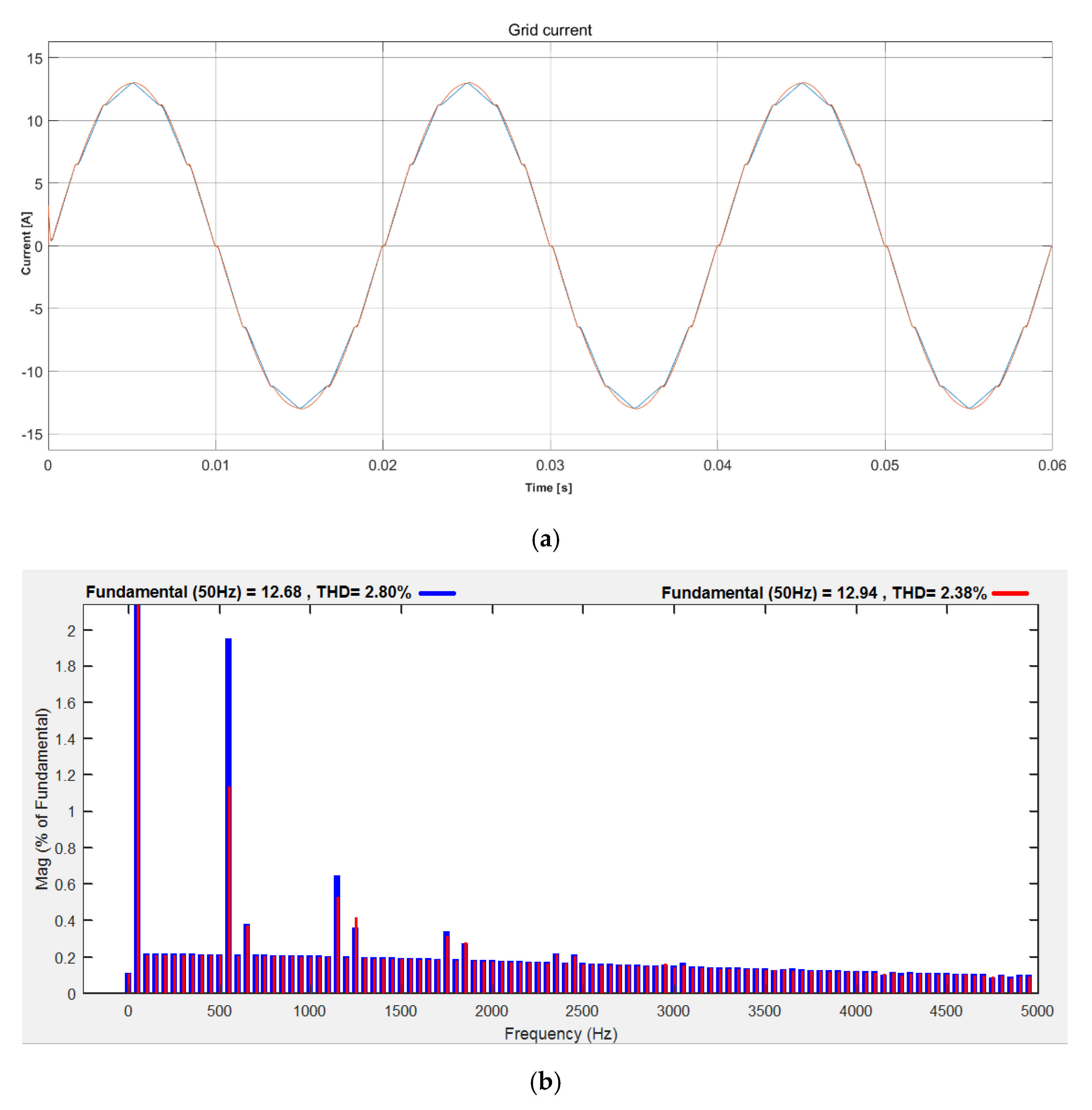
2.2. Selected Results of Simulation Tests

Using previously developed simulation models, they were expanded with a supporting system. This system is built on the basis of a linear current source. An example of the implementation of this system is shown in Figure 15.
The simulation tests were carried out for two cases of implementation of the main CM current modulator module, namely:
  • based on an ideal current source;
  • based on a transistor bridge with an output low-pass filter (frequency carrier signal was 10 kHz).
Selected test results are presented in Figure 16 and Figure 17, respectively.
Figure 18 shows, respectively, the grid current waveforms and their spectral analysis for the case of the diode rectifier with the CM current modulator based on the transistor H-bridge and with the CM2 support system in on and off state.
Based on the obtained test results, it can be concluded, that the use of the additional CM2 supporting system with the simultaneous use of the CM current modulator in rectifier systems allows further improvement of the quality of grid currents. In the analyzed cases, the following results were obtained for the reduction of THD coefficients in the considered frequency band:
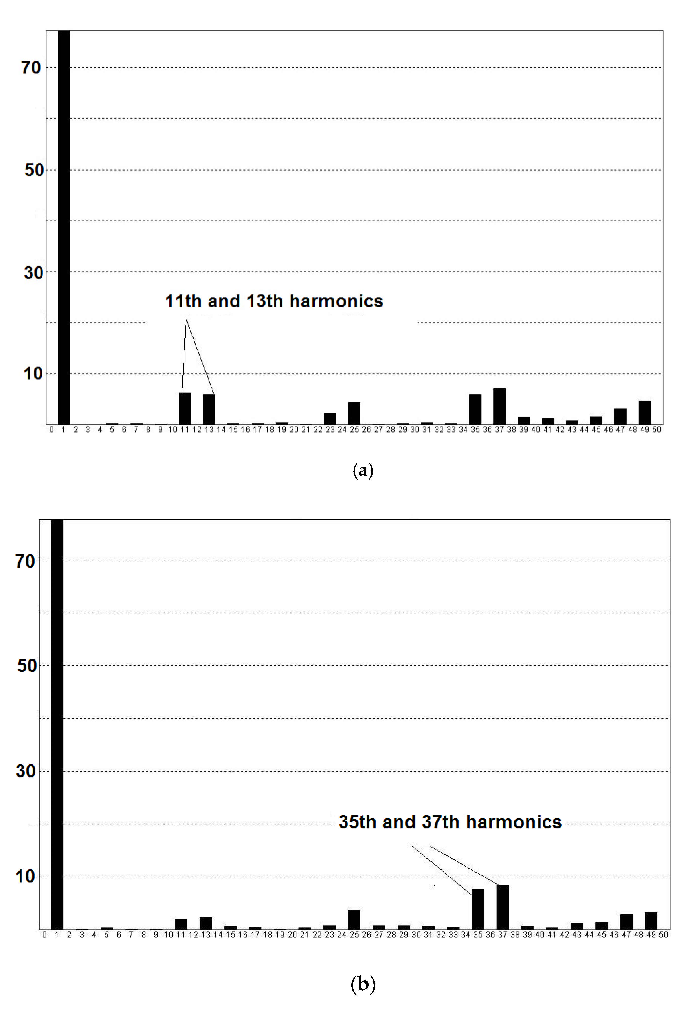
  • for the linear CM module: from THD = 1.05% to THD = 0.08%;
  • for the CM module based on the transistor H-bridge: from THD = 2.80% to THD = 2.38%.
In the case of the implementation of the CM module on the basis of the transistor circuit, it should be emphasized that there is a possibility of further improvement of the quality of the converted energy by optimizing the structure and parameters of the regulator used in the control system of the power electronics current modulator CM. However, this topic was not the subject of this research.

3. Parameters of the Built Experimental Model

Simultaneously with the simulation works, the experimental model of the described rectifier with current modulation and supporting system is being built. The following system parameters were assumed:
  • supply voltage: 3 × 400 V;
  • output power: 6 kW;
  • output voltage (DC voltage): 180 V;
  • PWM’s carrier frequency: 10 kHz.
For this purpose, the following chosen components were elaborated:
  • designed and built impulse transformer (IT);
  • main circuit of current modulator, which is based on universal power electronics converter with PM50RSA120 IGBT module form Mitsubishi Electric [21];
  • digital control system based on DSP procesor ADSP ADSP-21369 form Analog Devices [22].
The additional current source working as a supporting system, the energetic transformers with appropriate groups of connections and the diode rectifiers are at this moment under construction.
The equivalent circuit of real IT pulse transformer is shown in Figure 19. The values of all components have been calculated in an experimental way. All parasitic capacitors, existing in every real transformer, have been omitted due to their very small influences on circuit, which has been verified during tests.
A detailed description of the construction of the experimental system, implemented control algorithms and the obtained test results will be the subject of the next article.

4. Conclusions

The article presents methods of improving the quality of energy conversion in rectifier systems with the use of the voltage and current modulator in DC circuits. However, the main topic of the research was the use of current modulation. This solution is very attractive due to the ease of implementation in systems already in use, which significantly reduces investment costs. It should be noted that already in its basic version this solution enables a significant reduction of undesirable harmonics in the grid current, which has a positive effect on the quality of the converted energy. The development of the system with the additional CM2 supporting system enables further improvement of the quality of electrical signals. An additional advantage of the presented system is its low power, reaching respectively for CM and CM2 modules: 2.35% and 1.7% of the load power of the entire system. It should also be emphasized that even a possible failure of these modules does not interrupt energy supply to the load.
As part of the next stages of research, the authors predict construction of an experimental system and conducting tests for selected operating conditions of the system (in the version with CM modules and CM2 supporting modules). Work is also underway on the development of a new power circuit and control structure for controlled current source modules in order to reproduce the reference signals in the grid signals of the rectifier system with highest fidelity possible.

Author Contributions

Conceptualization and formal analysis, M.K.; methodology, resources, writing—original draft preparation, writing—review and editing, D.M., M.K. and T.P.; software, investigation, data curation, visualization, D.M., M.K.; validation, D.M. and T.P.; supervision and project administration, M.K. and T.P.; funding acquisition, T.P. All authors have read and agreed to the published version of the manuscript.

Funding

This work has been founded by Poznan University of Technology under project 0214/SBAD/0221.

Institutional Review Board Statement

Not applicable.

Informed Consent Statement

Not applicable.

Data Availability Statement

The data presented in this study are available on request from the corresponding author. The data are not publicly available due to privacy reasons.

Conflicts of Interest

The authors declare no conflict of interest.

References

  1. Singh, B.; Bhuvaneswari, G.; Garg, V. Harmonic mitigation using 12-pulse AC-DC converter in vector-controlled induction motor drives. IEEE Trans. Power Deliv. 2006, 21, 1483–1492. [Google Scholar] [CrossRef]
  2. Deshpande, A.A.; Dhend, M.H. Detection and evaluation of harmonics in 6 pulse and 12 pulse converter. In Proceedings of the 2016 International Conference on Automatic Control and Dynamic Optimization Techniques (ICACDOT), Pune, India, 9–10 September 2016; pp. 278–283. [Google Scholar] [CrossRef]
  3. Rozanov, Y.; Ryvkin, S.; Chaplygin, E.; Voronin, P. Fundamentals of Power Electronics: Operating Principles, Design, Formulas, and Applications; CRC Press: Boca Raton, FL, USA, 2015. [Google Scholar]
  4. Shklyarskiy, Y.; Hanzelka, Z.; Skamyin, A. Experimental Study of Harmonic Influence on Electrical Energy Metering. Energies 2020, 13, 5536. [Google Scholar] [CrossRef]
  5. McRee, B.J.; Dodson, D.A.; Wetz, D.A.; Cohen, I.J.; Heinzel, J.M.; Dong, Q. Investigation of harmonic distortion in multi-pulse rectifiers for large capacitive charging applications. In Proceedings of the IEEE International Power Modulator and High Voltage Conference (IPMHVC), San Francisco, CA, USA, 5–9 July 2016; pp. 404–408. [Google Scholar] [CrossRef]
  6. Kocman, S.; Kolar, V.; Trung Vo, T. Elimination of harmonics using multi-pulse rectifiers. In Proceedings of the 14th International Conference on Harmonics and Quality of Power—ICHQP 2010, Bergamo, Italy, 26–29 September 2010; pp. 1–6. [Google Scholar] [CrossRef]
  7. Akagi, H.; Nabae, A.; Atoh, S. Control Strategy of Active Power Filters Using Multiple Voltage-Source PWM Converters. IEEE Trans. Ind. Appl. 1977, 22, 361–368. [Google Scholar] [CrossRef]
  8. Supronowicz, H.; Strzelecki, R. Filtering of Harmonics in AC Power Grid; Wydawnictwo Adam Marszałek: Toruń, Poland, 1998. [Google Scholar]
  9. Frąckowiak, L.; Gwóźdź, M.; Porada, R. Compensation of influence of receivers on power network with application of power electronic current source. In Proceedings of the 7th European Conference on Power Electronics and Applications, EPE’97, Trondheim, Norway, 8–10 September 1997; Volume 4, pp. 886–891. [Google Scholar]
  10. Gwóźdź, M.; Porada, R. The Power Electronics Active Filter With Increased Quality of Output Current. In Proceedings of the 4th International Workshop CPE 2005 Compatibility in Power Electronics, CPE2005, Gdynia, Poland, 1–3 June 2005. [Google Scholar]
  11. Sampreeth, S.J. Implementation of Transistor Rectifiers and Comparison with Diode Rectifiers. Int. J. IT Eng. (IJITE) 2020, 8, 1–15. [Google Scholar]
  12. Supronowicz, H.; Strzelecki, R. Power Factor in AC Power Systems and Methods of Its Improvement; OWPW: Warszawa, Poland, 2000. [Google Scholar]
  13. Rolek, J. Analysis of Systems with a Parallel Connection of Diode Converters with Modulation in the DC Circuit. Ph.D. Thesis, Kielce University of Technology, Kielce, Poland, 2011. [Google Scholar]
  14. Rashid, H.M. Power Electronics Handbook: Devices, Circuits, and Applications; Elsevier: Amsterdam, The Netherlands, 2011. [Google Scholar]
  15. Gwóźdź, M.; Krystkowiak, M.; Jędryczka, C.; Gulczyński, A.; Matecki, D. Generator with modulated magnetic flux for wind turbines. Bull. Pol. Acad. Sci. Tech. Sci. 2017, 65, 469–478. [Google Scholar] [CrossRef]
  16. Choi, S.; Enjeti, P.; Hoag-Hee, L.; Pitel, I. A new active interphase reactor for 12-pulse rectifiers provides clean power utility interface. IEEE Trans. Ind. Appl. 1996, 32, 1304–1311. [Google Scholar] [CrossRef]
  17. Strzelecki, R.; Supronowicz, H. Power Factor in AC Power Supply Systems and Methods for Its Improvement; Publishing House of the Warsaw University of Technology: Warsaw, Poland, 2000. (In Polish) [Google Scholar]
  18. Krystkowiak, M.; Gwóźdź, M. Three-phase diode rectifier with current modulator in DC circuit based on multi-channel converter. Arch. Electr. Eng. 2017, 66. [Google Scholar] [CrossRef]
  19. Krystkowiak, M.; Ciepliński, Ł.; Gwóźdź, M. Methods of Current Modulation in Diode Rectifiers. In Proceedings of the 2019 Progress in Applied Electrical Engineering (PAEE), Koscielisko, Poland, 17–21 June 2019; pp. 1–5. Available online: https://ieeexplore.ieee.org/document/8788977 (accessed on 28 March 2021). [CrossRef]
  20. Franco, S. Design with Operational Amplifiers and Analog Integrated Circuits, 4th ed.; McGraw-Hill Education: New York, NY, USA, 2015. [Google Scholar]
  21. Datasheets.pdf. Available online: https://datasheetspdf.com/datasheet/PM50RSA120.html (accessed on 9 March 2021).
  22. Analog Devices. Available online: https://www.analog.com/media/en/technical-documentation/data-sheets/ADSP-21369.pdf (accessed on 9 March 2021).
Figure 1. Circuit diagram of the rectifier system with the voltage modulator on the DC circuit side.
Energies 14 01876 g001
Figure 2. Waveform of selected signals for the rectifier with the voltage modulator: (a) current of the primary side of the transformer with star-star connection, (b) current of the primary side of the transformer with star-delta connection (c) waveform of the resultant grid current.
Energies 14 01876 g002
Figure 3. Spectral analyses of the grid current for the rectifier with the voltage modulator: (a) the system without the voltage modulator (THD = 15.7%), (b) the system with the voltage modulator (THD = 9%).
Energies 14 01876 g003
Figure 4. Schematic diagram of the rectifier with the current modulator (CM).
Energies 14 01876 g004
Figure 5. The waveform of the grid current (iL1) drawn by the rectifier with the current modulator (the current modulator is based on an ideal current source).
Energies 14 01876 g005
Figure 6. Spectral analysis of the grid current (iL1) drawn by the rectifier with the current modulator (the current modulator is based on an ideal current source).
Energies 14 01876 g006
Figure 7. Schematic diagram of the current modulator based on the H-bridge structure with the output filter.
Energies 14 01876 g007
Figure 8. The waveform of the grid current (iL1) drawn by the rectifier with the current modulator (the current modulator is based on the H-bridge with the output filter).
Energies 14 01876 g008
Figure 9. Spectral analysis of the grid current (iL1) drawn by the rectifier with the current modulator (the current modulator is based on the H-bridge with the output filter).
Energies 14 01876 g009
Figure 10. Reference (blue) and output (red) current waveforms for the current modulator based on the H-bridge.
Energies 14 01876 g010
Figure 11. The calculated curves of the simulation models’ efficiency vs. the relative system’s output power for both elaborated models of rectifiers.
Energies 14 01876 g011
Figure 12. Schematic diagram of the rectifier with the current modulator and an additional supporting system CM2.
Energies 14 01876 g012
Figure 13. Block diagram of the algorithm determining the shape of the reference signal of the CM2 supporting system.
Energies 14 01876 g013
Figure 14. Block diagram of the algorithm that determines the amplitude of the reference signal of the CM2 supporting system.
Energies 14 01876 g014
Figure 15. An example of the implementation of the supporting system [20].
Energies 14 01876 g015
Figure 16. Grid current (iL1) drawn by the rectifier with CM current modulator (based on an ideal current source) and CM2 supporting system: (a) waveform, (b) spectral analysis.
Energies 14 01876 g016aEnergies 14 01876 g016b
Figure 17. Grid current (iL1) drawn by the rectifier with CM current modulator (based on H-bridge with output filter) and CM2 supporting system: (a) waveform, (b) spectral analysis.
Energies 14 01876 g017
Figure 18. Comparison of: (a) grid current (iL1) waveform for the case of the diode rectifier with the CM current modulator based on the transistor H-bridge and on (red) and off (blue) CM2 supporting system, (b) spectral analysis.
Energies 14 01876 g018
Figure 19. The equivalent circuit of real IT pulse transformer (Rcu-resistance of the windings, Rfe-resistance representation of the iron core losses, Lr-inductance of the windings, Lu-main inductance).
Energies 14 01876 g019
Table 1. Parameters of the diode rectifier with current modulator.
Name of BlockQuantityValue
GridNominal voltage510 V
Phase’s self-inductance (star section)220 μH
Phase’s resistance
(star section)
2.5 mΩ
Phase’s self-inductance (delta section)450 μH
Phase’s resistance
(delta section)
3.0 mΩ
Diode rectifiers (R1, R2)Rated output voltage720 V
Current modulator (CM)Rated output power45 kW
Rated efficiency97.4%
Output inductor350 μH
PWM carrier frequency20 kHz
Resistance (this respects resistance of the IT secondary side winding)0.3 mΩ
Capacitor in DC circuitCapacitance10 mF
Table 2. Parameters of the transistor rectifier in 3-channel version.
Name of BlockQuantityValue
GridNominal voltage510 V
Phase’s self-inductance150 μH
Phase’s resistance1.15 mΩ
DC circuitRated voltage720 V
Transistor rectifierInductance of coil associated with inverter’s leg125 μH
Resistance of coil associated with inverter’s leg0.15 mΩ
PWM carrier frequency3 kHz
No of legs per inverter’s phase3
Publisher’s Note: MDPI stays neutral with regard to jurisdictional claims in published maps and institutional affiliations.

