Article

Polystyrene Waste in Panels for Thermal Retrofitting of Historical Buildings: Experimental Study

by
Bożena Orlik-Kożdoń
Faculty of Civil Engineering, Silesian University of Technology, 44-100 Gliwice, Poland
Energies 2021, 14(7), 1844; https://doi.org/10.3390/en14071844
Submission received: 1 March 2021 / Revised: 18 March 2021 / Accepted: 23 March 2021 / Published: 26 March 2021
(This article belongs to the Section G: Energy and Buildings)

Abstract

:
The following article presents comprehensive research results for the insulation material based on polystyrene wastes. The presented product has the form of plates to be applied for thermal insulation of external envelopes from the inside. The laboratory tests were focused on the determination of basic technical parameters for this type of materials, i.e., thermal conductivity coefficient, diffusion resistance coefficient, reaction to fire, material sorption, and strength characteristics. For the recycling material, the obtained thermal conductivity value was 0.055 [W/mK]. The diffusion resistance coefficient was 5 [–], and therefore, this component has been qualified to a group of solutions that allow for interstitial condensation in the envelope. For the developed product, in situ tests were carried out on the actual wall system in a historical building. Based on the research, temperature and humidity profiles were obtained in the selected planes of the envelope. The performance of this material in real conditions was observed in relation to the reference product, i.e., lightweight cellular concrete (commonly used as thermal insulation from the inside). For the conducted in situ research, statistical inference was applied, which included the verification of the hypothesis-recycling panels in wall systems follow a trend of changes similar to that of slabs made of lightweight cellular concrete (a group of materials that allows for interstitial condensation). The proposed method of using secondary raw materials in insulation products allows us to obtain a product with high technical parameters that do not differ in quality from new components.

1. Introduction

The care and protection of the environment as well as the improvement of life quality enforces the application of a suitable waste management policy. It mainly involves the recovery of raw materials through recycling and the disposal of wastes that cannot be reused. The greatest potential for the utilization of wastes is offered by the construction sector of the economy [1,2,3].
Buildings or building objects must be designed, constructed, and dismantled in the way of ensuring the reuse or recycling of the recovered materials and the application of environmentally friendly raw materials or secondary materials [4,5,6,7,8,9].
The assessment involving the impact of a given product (in terms of materials used) on the environment has been the subject of many research studies [2,3,10,11].
The recovery of raw materials is also enforced in the Directive on Waste [11], which “encourages the re-use of construction materials and products.” In the directive, the Commission has undertaken to set significant targets for recycling construction and demolition waste by 2024. Until 2020, the assumption was to reach a 70% recycling target for this category.
The main aim of the study is to propose the use of polystyrene waste as a basic ingredient for the production of internal insulation panels.
Envelope insulation from the inside is a necessity in the case of historical buildings where the traditional External Thermal Insulation Composite Systems (ETICS) method based on standard insulation materials (e.g [12]) cannot be applied [13,14]. In most cases, these are buildings under conservation protection, those with high architectural value, or with limited options in terms of traditional ETICS methods. In this work, historical buildings are understood as architecturally, culturally, and historically valuable buildings, regardless of the legal status, built before 1945 [15]. As part of the EU research project EFFESUS (Energy Efficiency for EU Historic Districts′ Sustainability), measures and tools were investigated that could significantly improve energy efficiency of such buildings. Historic urban buildings consume 4% of all energy and are responsible for 3% of CO2 emissions [15]. Therefore, the improvement of energy efficiency in historic buildings and historic districts is essential. Problems involving energy savings in this type of buildings have been addressed in the publications [16,17,18,19,20,21,22]. Due to design and technological difficulties, instruction manuals and guidelines for thermal insulation from the inside are provided for such solutions [23,24,25]. Nowadays, there are lots of materials dedicated to internal insulation [26,27,28,29,30] (Table 1). The table presents all materials that can be used as internal insulation.
Taking into account the used raw material, production method, and assembly technology, the materials can be classified as solutions to the following [31]:
  • Insulation from the inside preventing the development of condensation with the application of thermal insulation material, so that the value of the diffusively equivalent air layer thickness Sd of the thermal insulation and/or the applied vapor barrier exceeds 1500 m.
  • Insulation from the inside minimizing the development of interstitial condensation with the use of diffusion resistance materials, for which the total, diffusively equivalent air layer thickness Sd is contained between 0.5 and 1500 m.
  • Insulation from the inside allowing the condensation to develop, on condition that justification or proof is provided that the condensate formed during the unfavorable period evaporates during the calculation year.
The present insulating panel, due to its hygrothermal properties, is classified as the third group (3). However, the use of raw materials in this type of solution is not common.
The search for new insulation solutions is of key importance due to the requirements of the Energy Efficiency Directive [32], which puts homeowners and developers under an obligation to improve the energy quality of buildings, including historical buildings.
It is estimated that the action provoked by the introduction of directives will contribute to the reduction of energy needs for heating and cooling by 8% in 2020, 12% in 2030, and 17% in 2050 [32,33].
The author, in line with the current of ecological and energy activities [32,33], presents a new product for thermal insulation in the form of recycling panels.
The article presents the possibility of using polystyrene waste in the production of insulation panels for thermal insulation of historic buildings. Thus, the study covers the following issues:
  • presentation of the production method and material composition;
  • laboratory tests including the determination of the basic characteristics of this type of insulation materials;
  • in situ tests carried out in a building that has undergone thermal modernization-thermal insulation of external envelopes from the inside; in situ tests were carried out with reference to the material commonly used in these solutions, i.e., lightweight concrete (description of the solution in wpc.); the purpose of in situ research was to confirm the effectiveness of the new component;
  • thermovision analysis conducted in a building that has undergone thermal modernization-as a control test.

2. Materials and Methods

2.1. Recycling Panels

The panels are primarily dedicated to thermal insulation from the inside, but they can also be used as insulation of diaphragm walls, insulation of voids in walls, and insulation of ceilings (Figure 1).
The panels are made on the basis of polystyrene regranulate with the granule diameter of 2 ÷ 6 mm. CEM I 42.5R Portland cement was used as a binder. Additionally, micro-reinforcement in the form of PP (polypropylene fibers) shavings and air-entraining admixture as well as hydrated lime were added to the mixture. The exact composition of the mixture is protected by a confidentiality clause.
This innovative solution relies upon:
  • the use of polystyrene waste, which increases thermal insulation of the panels;
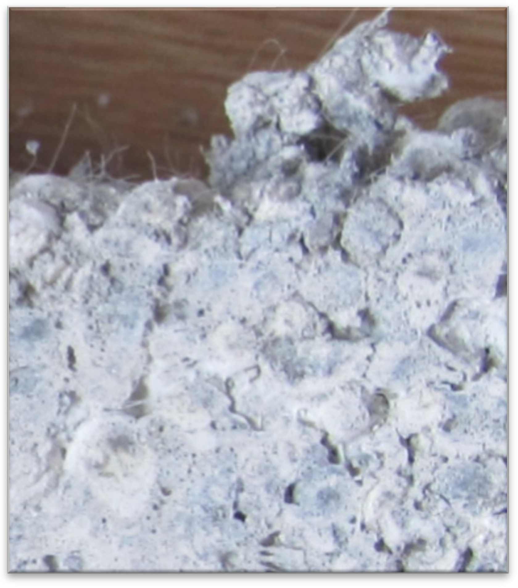
  • the use of microfibers that increase resistance to mechanical damage and cracks related to the process of assembly, transport, storage, or conditions of use (Figure 1);
  • production technology enabling board formation of various shapes and dimensions so that the boards are “tailored” to the needs of property developers and builders.

2.2. Structure of the Tested Component

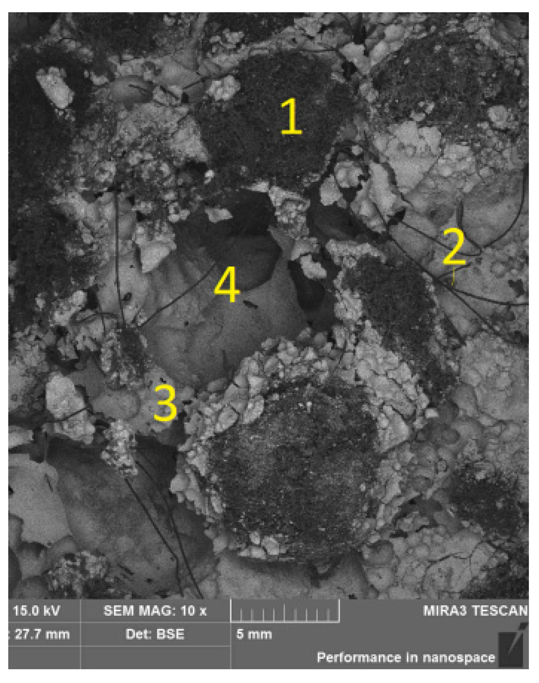
The microscopic observations show the presence of three main components that make up the material under consideration (Figure 2, Figure 3 and Figure 4). We can distinguish: (1) polystyrene grains/fragments and (2) organic fibers-playing the role of micro-reinforcement, embedded in (3) a fine-grained matrix/bound binder. Moreover, the material has distinct voids, empty spaces (pores) (4). In terms of chemical composition, carbon, oxygen, and calcium were identified as the main components; silicon and aluminum as accompanying components; and iron, sulfur, potassium, and magnesium as trace components. The mapping of the distribution of elements indicated the presence of carbon mainly in polystyrene grains and in fibers. The remaining elements accumulate in the fine-grained matrix of the product-the binder that holds the composite together, and they have relatively uniform distribution.
With regard to polystyrene grains, the tested material contains grains with a size of several millimeters. When inspecting these fragments at higher magnification, the characteristic “folded” surface of polystyrene grains was found (Figure 4a), on which, locally, the presence of fine-grained forms coming from the binder was identified. As to the chemical aspect, the presence of carbon dominates. The observations of fibers indicate that they have a relatively smooth, uniform surface. The thickness of the fibers is about 0.15 mm. The presence of carbon in the EDS analysis indicates the organic nature of the fibers. With regard to the binder, at the places of fracture/cross-section of the sample through that part, it is observed as jagged, bushy fine-grained forms (Figure 4c). At the contact places with polystyrene fragments (after their removal at the stage of sample preparation), a relatively smooth, compact surface is observed. In those parts of the material, the presence of such elements as O, Ca, and Si is identified. In all the above cases, fine grain size is observed, coming from the binder and developing presumably at the stage of sample preparation for the observation.

3. Research

3.1. Laboratory Tests

The material was tested to measure the required parameters for lightweight concretes in compliance with the European Assessment Document (EAD): 040012-00-1201040012-00-1201).
Their own research [34] comprised the following physical features of the plate material [35,36,37,38,39] (Figure 5 and Figure 6):
  • thermal conductivity coefficient (hot wire method and in a plate apparatus),
  • diffusion resistance coefficient,
  • density,
  • pH reaction,
  • long term water absorption by immersion,
  • initial rate of water absorption,
  • water absorption, and
  • reaction to fire.
The research was carried out in accordance with the principles specified in the standards for the determination of individual quantities [35,36,37,38,39] (e.g., vapor permeability), or the assessment of their performance under specific conditions, e.g., sorption.
On the basis of the conducted tests, a batch of readymade plates was fabricated for further testing, being a final test of the finished system—a plate with internal plaster. Two types of internal plasters were used in the samples: perlite plaster and plaster based on Triassic material adapted to historic buildings for walls with raised mortar humidity.

3.2. In Situ Tests

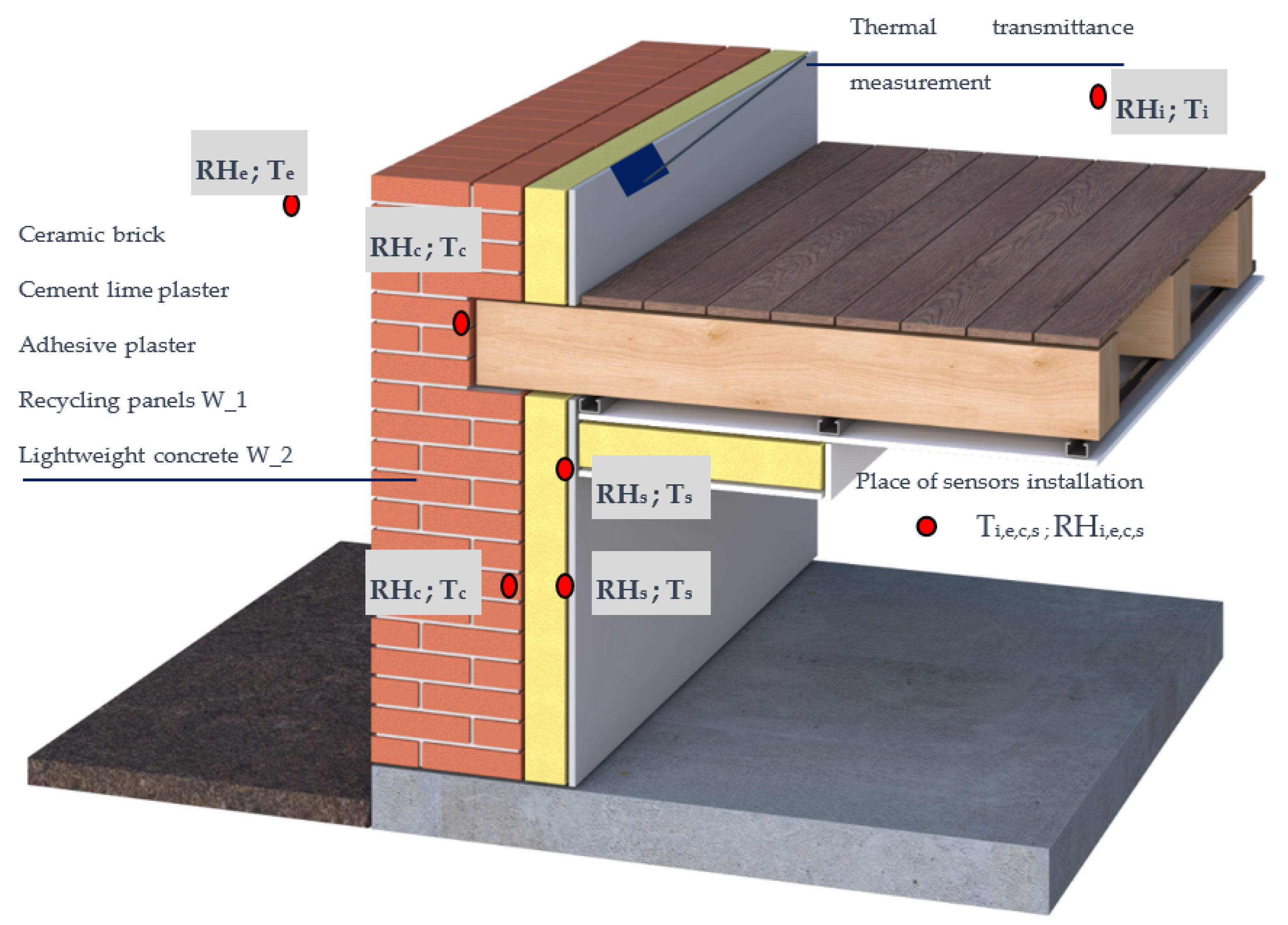
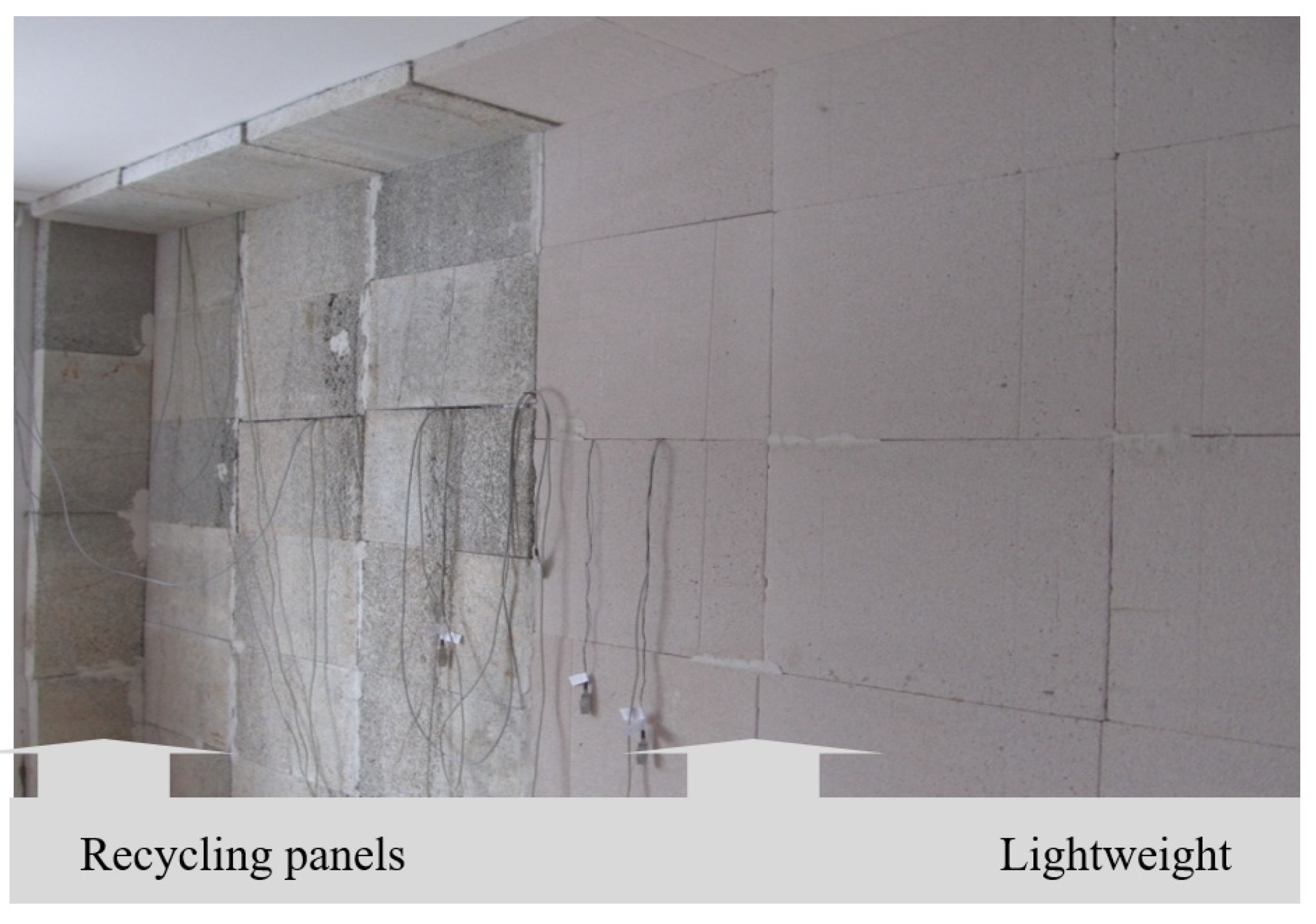
The main research stand was set up in a single-family building erected in 1928, located in Upper Silesia, Poland. Information about the building, i.e., its technical condition, material, and construction solutions, was obtained based on a site visit and archival documentation. The building is made in traditional technology. The external walls of the building are made of solid brick on cement-lime mortar. The walls of the ground floor are 38 cm thick and those of the first floor are 25 cm thick. The walls are covered by newly made double-sided cement-lime plaster and the building has wooden beam ceilings. New PVC window joinery was applied inside as well as traditional heating of the building—a coal stove. Selected utility rooms (living room, study) on the ground floor were insulated from the inside with 10 cm-thick insulation material. The selection of the thickness of the insulation was dictated by technical considerations, as well as by the recommendations given in the WTA document [32]. The thermal insulation included external walls (Figure 7 and Figure 8) with optional insulation of internal and external walls in the context of impact assessment of thermal bridges (see diagram, Figure 7).
The construction of the stand was preceded by comprehensive hygrothermal diagnostics of the wall, which was used in further hygrothermal analyses. With the consent of the building owner, samples of the material were collected for mass moisture measurement (using a moisture analyzer) and for the determination of brick porosity (using mercury porosimetry). The results of these tests will be used in numerical analyses of the tested wall systems (the study does not cover this type of analyses). In addition, a control measurement of thermal transmittance coefficient was performed using a measuring set gSKIN® KIT-2615C (rys.17, 18).
All the panels were glued across the entire surface to the wall. In each case, a system mortar was used. In selected places of the envelope, a system of temperature (Pt100) sensors and relative air humidity (HIH 4000) sensors connected to APAR AR 207 type recorders was used. The places of sensor installation are presented in the diagram (Figure 8).
In the building, insulation material in the form of lightweight cellular concrete slabs was used to insulate a part of the wall—the reference material. It is a product commonly used for internal insulation. Due to its technical features (thermal conductivity, diffusion resistance, etc.), it is a material similar to the recycling plates in question and belongs to the group of solutions ensuring free transport of water vapor (group 3).
In the work, it was marked with the symbol W_2, (W_1-recycling panels). The features of the W_2 material are given in Table 2.
The objective of the research was to determine the profiles of temperature and humidity changes in selected planes of the envelope. The intention of the author was to compare the behavior of two different material solutions in real conditions and to determine the correctness of the solution with recycling panels. The solution with lightweight cellular concrete slabs was a benchmark for the comparative analysis.

4. Result and Discussion

4.1. Laboratory Results

The basic technical characteristics of the material, shown in the table, were determined on the basis of laboratory tests.
A statistical analysis of the obtained results was carried out for the conducted research. The error was determined by the maximum uncertainty method. The selected test results are presented below in Table 3.

4.2. In Situ Test Results

The in situ tests for the analyzed wall systems were carried out with breaks from 2014 to the present day. The measuring step was 1 h.
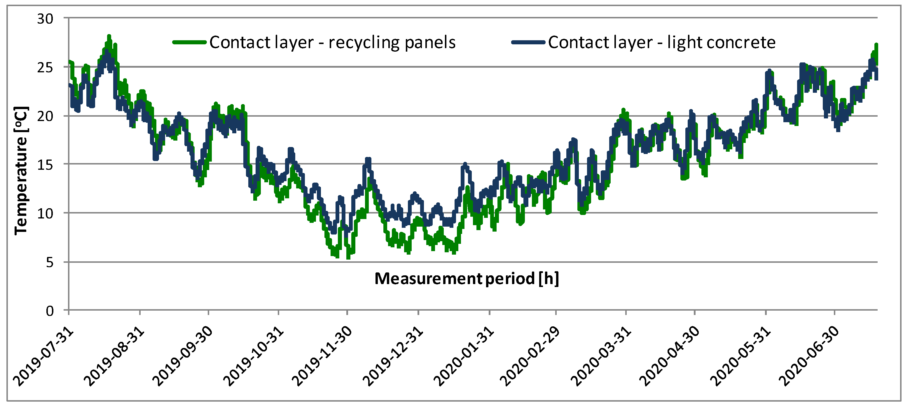
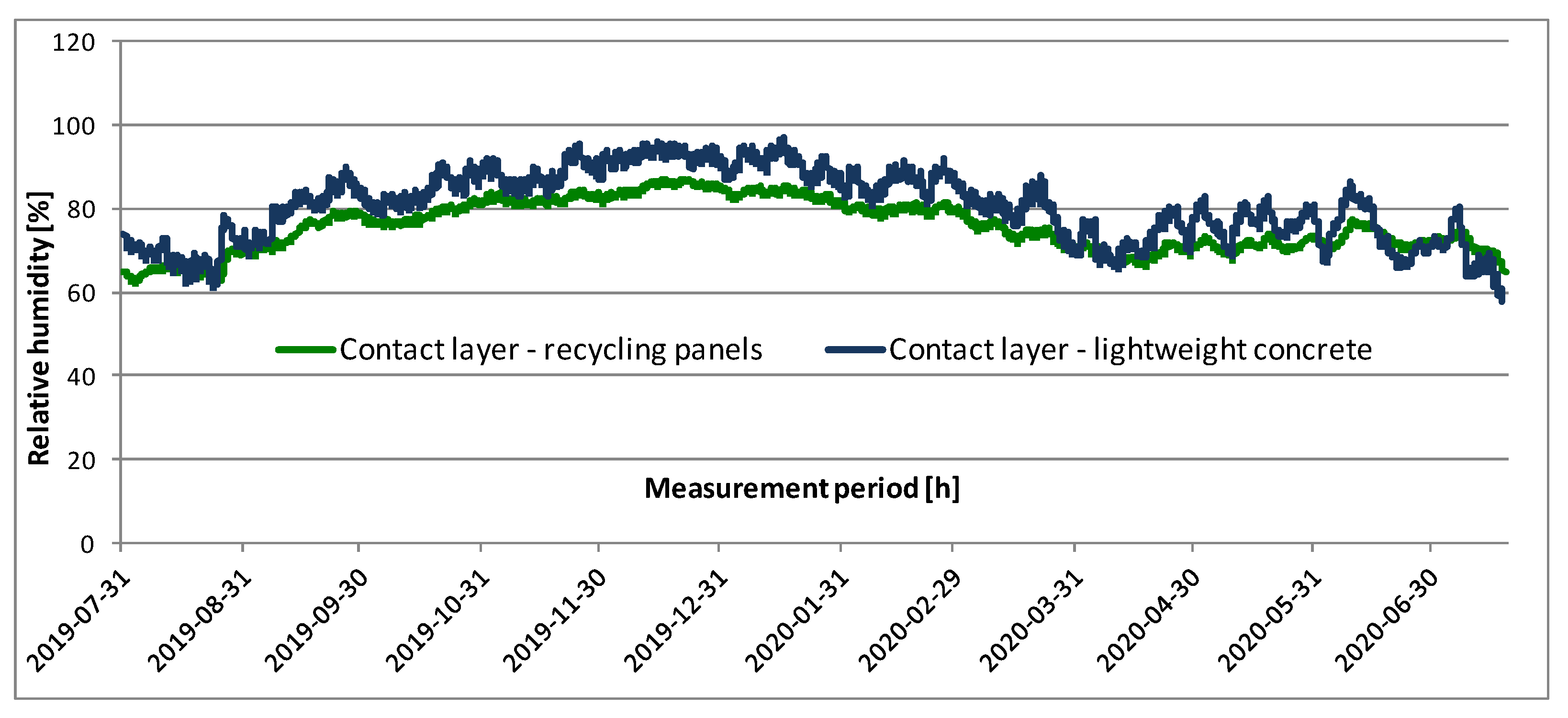
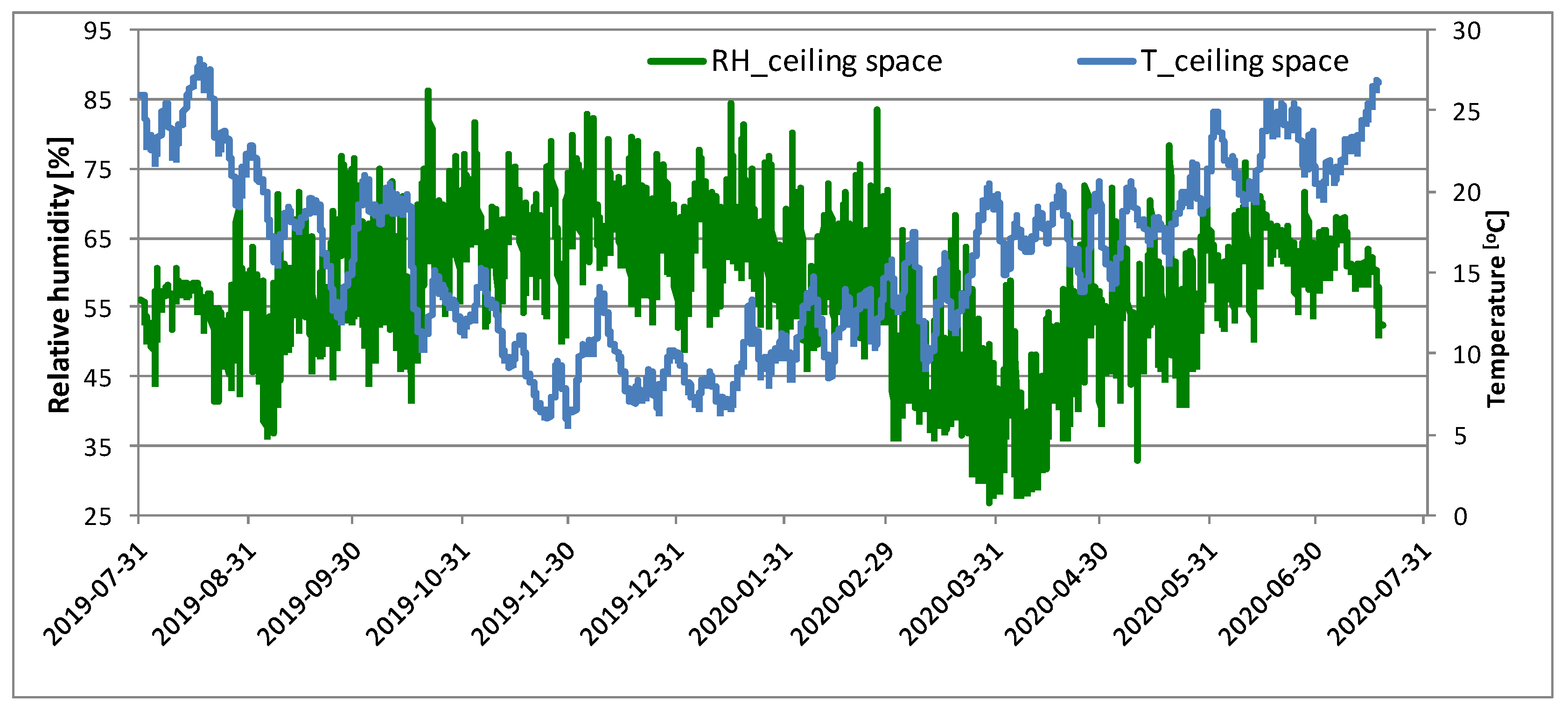
Figure 9, Figure 10 and Figure 11 present the selected measurement period of one year from July 2019.
When observing the changes of temperature in the contact layer, we can see that it is strongly influenced by the external environment—high summer temperatures reaching 30 °C (with an average air temperature of 22 °C), and low temperatures in winter, falling to 4 °C (with an average air temperature of 1.2 °C). In combination with high humidity at that time, this situation may not only lead to condensation of water vapor and freezing of the envelope, but also to the degradation of the wall system. The difference in temperature distributions (for average values) for variants W_1 and W_2 ranges from 0.3 °C to 1.7 °C.
The course of changes in relative humidity demonstrates that it rises considerably in the winter season at the contact point between the insulating material and the brick wall. For the thermal insulation variant based on recycling panels (W_1), the value of humidity is above 80%. The difference in the profiles of humidity changes in time ranges from 1% to 16% (for average values) in favor of the W_1 variant (lower value of relative humidity at the contact place between the brick wall and the recycling material).
A high value of relative humidity in the ceiling space at the front of the wooden beam, which reaches 85%, can be considered disturbing. During this time period, the temperature ranges from 5 °C upwards. Such conditions can provoke the growth of mold and progressive biological corrosion. This problem is discussed in more detail in [20].
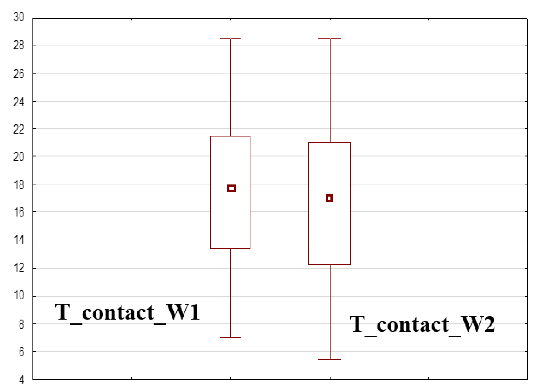
For the analyzed variants of thermal insulation (W_1/W_2), statistical tests with equal means were performed. It was assumed that the average profile of temperature changes in the contact layer is the same for both thermal insulation variants (Figure 12, Figure 13, Figure 14 and Figure 15). The assessment of the correctness of the adopted hypothesis was based on the value of p (the so-called test probability). When it was lower than the accepted significance level of the test α (α = 0.05), the hypothesis was rejected.
Based on the obtained value of p = 0.00 with the adopted confidence level of 0.05, we can make a decision to reject the tested hypothesis (Table 4 and Table 5)
Figure 12, Figure 13, Figure 14 and Figure 15 present the remaining results of the statistical analysis conducted for the dependent samples.
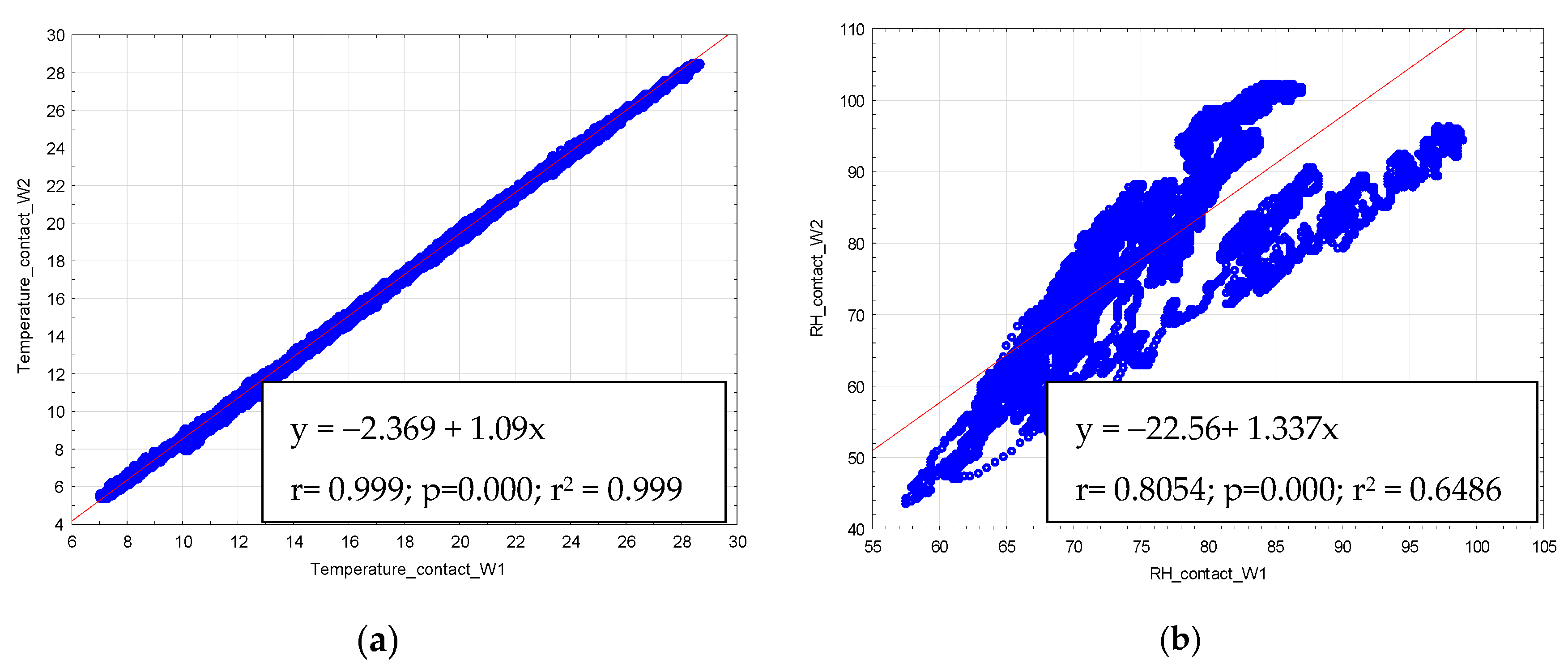
In the next phase, the relationship between the analyzed distributions for two different thermal insulation variants was determined (Figure 16). For this purpose, the Pearson′s linear correlation coefficient was used. For the linear relationship between the temperature distribution profiles for variants W_1 and W_2, the correlation coefficient is r = 0.9996. Both distributions are characterized by high proportion of mutual variability, and it amounts to r2 (coefficient of determination) = 0.9992.
We can state that the tendency involving the behavior of two differently insulated wall systems in terms of temperature changes is the same.
When comparing the changes in humidity in the contact plane for the analyzed variants, there is no compliance in the trend of changes. It is caused by different properties of materials in terms of sorption and water absorption. Both insulators are characterized by a similar value of diffusion resistance coefficient (compare Table 2 and Table 3). However, this feature is insufficient to maintain similarity in the process of mass transport, and consequently, in the drying process of the envelope.
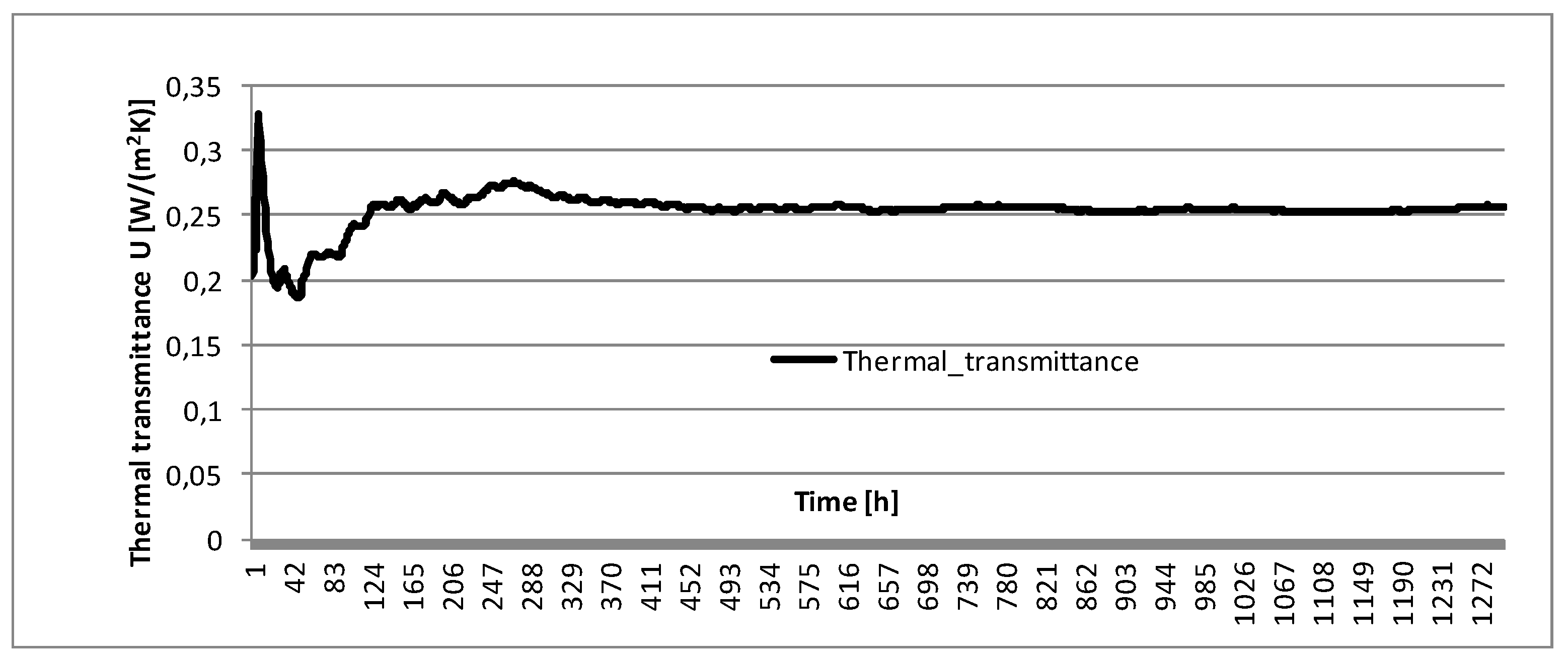
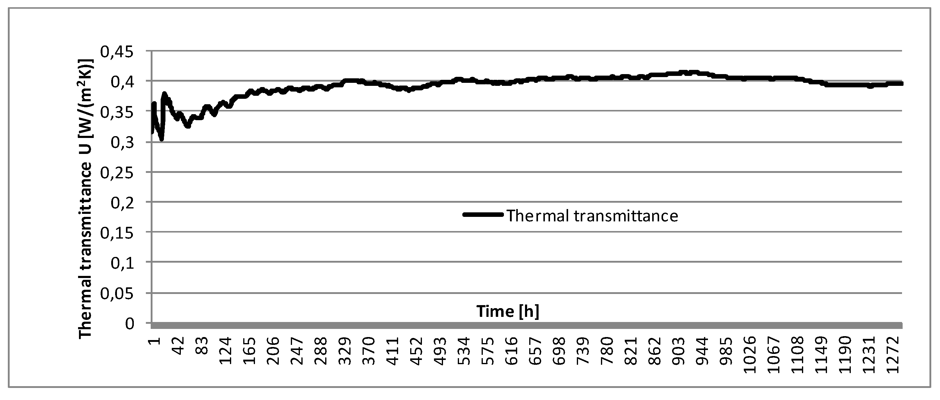
It should be noted that the applied recycling panels (W_1) were characterized by a worse thermal conductivity coefficient than the lightweight cellular concrete panels (W_2). Moreover, the entire insulated wall was characterized by a higher thermal transmittance coefficient U [W/m2K]. For the wall in the first variant, W_2, the value of the coefficient was 0.25 [W/(m2K)], and for the wall W_1 insulated with the recycling panels, U = 0.39 [W/(m2K)] (Figure 17 and Figure 18).
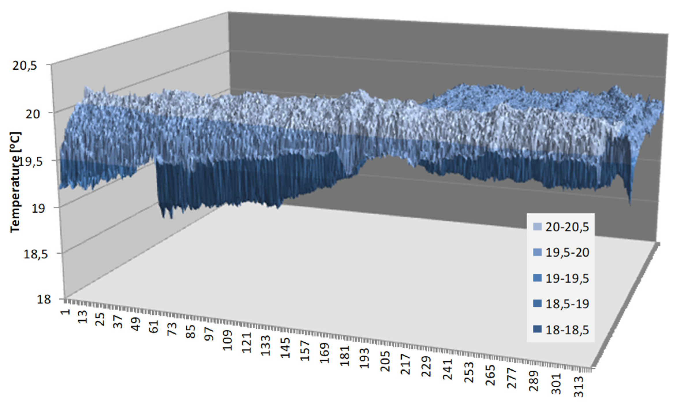
Figure 19 and Figure 20 present the results of thermal imaging examinations. They were made using a Flir E8 infrared camera with the accuracy of 0.06 °C. The tests had illustrative characters. On their basis, slight differences in temperature field on the surface of the two analyzed wall systems were found. For the wall insulated with the recycling material, the temperature on the wall surface in the analyzed field was lower, within the range from 0.5 °C to 0.8 °C (Figure 19 and Figure 20).

5. Conclusions

The thermal insulation system based on recycling panels meets the assumptions involving the performance of this type of materials for group 3 (point 1). In the winter season, a rise in water content is observed, but in the summer season, the water dries out. Moreover, for the entire observed period, no increase in water content exceeding 30% of saturation ([23] WTA) was observed (i.e., 30% of the maximum water content wmax).
For its fabrication, only one mechanical device is needed—a mixer that can ensure proper mixing of particular components and a weighing machine for proper dosing of the ingredients. Molds for the production of plates are reusable, and the production process does not generate any wastes in solid or liquid form. The costs of the entire technological process and, hence, those of the entire internal insulation system are much lower as compared to traditional materials, and according to preliminary estimates, the costs are by about 50% lower than the cost of lightweight concrete blocks.
The material is easy to transport and to mount; it does not crumble, and it is easy to transport, to shape, and to glue directly in the apartment. It also has high resistance to the development of mold or fungi due to proper pH > 11. When applied merely on the envelopes, on a small insulation area in this system, the plates yield positive results as to the expected performance in the particular layers of the envelope in terms of humidity increment.
On the basis of in situ studies, it was found that the tendency of hygrothermal changes for both variants (W_1-recycling panels, W_2-reference material) is similar to each other—as both envelopes dry out, their thermal insulation increases. Quantitative discrepancies in the description (Figure 17 and Figure 18) result from the differences in the values of thermal conductivity, which is worse for recycling material (λ-0.55 [W/mK]. However, a lower increase of water is observed for recycling panels. It is important because for lightweight concretes, the increase in water content might lower thermal parameters and deteriorate insulation properties of the envelope.
The presented idea of the recycling component is reflecting the pursuit of the building construction sector to implement the principles of sustainable development within the framework of sustainable building construction.
The management of polystyrene waste seems necessary because of difficult recycling process of this material due to the presence of HBCD (Hexabromocyclododecane)—an additive that reduces the flammability of insulation panels. The use of HBCD as a flame retardant in EPS and XPS accounts for over 95% of its applications [40,41,42,43]. In Europe, the use of HBCD in isolation began in the 1980s. Therefore, the amount of HBCD-containing waste is expected to increase after 2025, which will be related to the renovation of their facades and other elements [43]. Although it is being removed from new panels, the past application in combination with other current applications creates a toxic reservoir of HBCD that can be released into the environment and harm human health.
The author focused in the work [44,45,46,47] mainly on developing such a material and a technological solution of internal insulations that would reconcile the needs of residents and eliminate adverse phenomena, such as biological corrosion or the condensation of water vapor in the envelope.
The applicability potential of various waste materials for the fabrication of building materials is contributing to better energy savings and to the protection of natural resources. It also encourages researchers to undertake further studies on the subject.
The author demonstrated in a simple way how to make use of a waste material that has a rather slim applicability potential. It should be emphasized that waste materials that are difficult to dispose of (high environmental burden) should be fully reused.
The subject involving the application of recycling materials presented in this paper is a part of a larger research cycle carried out by the author. It involves the use of waste materials and their further reapplication in the production of insulation products.

Funding

Publication supported under the Rector′s pro-quality grant. Silesian University of Technology no 03/030/RGJ20/0100.

Institutional Review Board Statement

Not applicable.

Informed Consent Statement

Not applicable.

Acknowledgments

The presented insulation material was developed as a result of the cooperation with AKCES BK Sp. z o.o (Poland) basing on the products of that company. The author expresses their thanks to the employees of the factory laboratory and to the quality control department for help and cooperation in the measurements. At the same time, I would like to thank the company′s management for kindness and valuable tips in the field of the technology being developed.

Conflicts of Interest

The authors declare no conflict of interest.

References

  1. Peterson, C. Building with Second Hand Stuff: How to Re-Claim, Re-Vamp, Re-Purpose & Re-Use Salvaged & Leftover Building Materials Paperback; Cool Springs Press: Franklin, TN, USA, 2011. [Google Scholar]
  2. Ng, W.Y.; Chau, C.K. New Life of the Building Materials Recycle, Reuse and Recovery. Energy Procedia 2015, 75, 2884–2891. [Google Scholar] [CrossRef] [Green Version]
  3. Saghafi, M.D.; Hosseini Teshnizi, Z.S. Recycling value of building materials in building assessment systems. Energy Build. 2011, 43, 3181–3188. [Google Scholar] [CrossRef]
  4. Ramesh, T.; Prakash, R.; Shukla, K.K. Life cycle energy analysis of buildings: An overview. Energy Build. 2010, 42, 1592–1600. [Google Scholar] [CrossRef]
  5. Cabeza, L.F.; Rincón, L.; Vilariño, V.; Pérez, G.; Castell, A. Life cycle assessment (LCA) and life cycle energy analysis (LCEA) of buildings and the building sector: A review. Renew. Sustain. Energy Rev. 2014, 29, 394–416. [Google Scholar] [CrossRef]
  6. Thormark, C. A low energy building in a life cycle—Its embodied energy, energy need for operation and recycling potential. Build. Environ. 2002, 37, 429–435. [Google Scholar] [CrossRef]
  7. Blengini, G.A. Life cycle of buildings, demolition and recycling potential: A case study in Turin, Italy. Build. Environ. 2009, 44, 319–330. [Google Scholar] [CrossRef]
  8. Blengini, G.A.; Di Carlo, T. The changing role of life cycle phases, subsystems and materials in the LCA of low energy buildings. Energy Build. 2010, 42, 869–880. [Google Scholar] [CrossRef]
  9. Turk, J.; Cotič, Z.; Mladenovič, A.; Šajna, A. Environmental evaluation of green concretes versus conventional concrete by means of LCA. Waste Manag. 2015, 45, 194–205. [Google Scholar] [CrossRef]
  10. Papadopoulos, A.M.; Karamanos, A.; Avgelis, A. Environmental Impact of Insulating Materials at the End of Their Useful Lifetιme. Protection and Restoration of the Environment VI. 2002. Available online: https://www.researchgate.net/profile/Agis-Papadopoulos/publication/237448672_environmental_impact_of_insulating_materials_at_the_end_of_their_useful_lifetime/links/0046352cede4daa9a6000000/environmental-impact-of-insulating-materials-at-the-end-of-their-useful-lifetime.pdf (accessed on 25 March 2021).
  11. European Union. Directive (EU) 2018/851 of the European Parliament and of the Council of 30 May 2018 Amending Directive 2008/98/EC on Waste; Brussels, Belgium, 2018. [Google Scholar]
  12. Krause, P.; Nowoświat, A. Experimental Studies Involving the Impact of Solar Radiation on the Properties of Expanded Graphite Polystyrene. Energies 2020, 13, 75. [Google Scholar] [CrossRef] [Green Version]
  13. Krause, P.; Nowoświat, A.; Pawłowski, K. The Impact of Internal Insulation on Heat Transport through the Wall: Case Study. Appl. Sci. 2020, 10, 7484. [Google Scholar]
  14. Zhou, X.; Carmeliet, J.; Derome, D. Influence of envelope properties on interior insulation solutions for masonry walls. Build. Environ. 2018, 135, 246–256. [Google Scholar] [CrossRef]
  15. Energy Efficiency in European Historic Urban Districts. A Practical Guidance. Available online: https://www.effesus.eu/wp-content/uploads/2016/06/effesus_booklet_final-version.pdf (accessed on 8 March 2021).
  16. Lu, J.; Marincioni, V.; Orr, S.A.; Altamirano-Medina, H. Climate Resilience of Internally-Insulated Historic Masonry Assemblies: Comparison of Moisture Risk under Current and Future Climate Scenarios. Minerals 2021, 11, 271. [Google Scholar] [CrossRef]
  17. Rieser, A.; Pfluger, R.; Troi, A.; Herrera-Avellanosa, D.; Thomsen, K.E.; Rose, J.; Arsan, Z.D.; Akkurt, G.G.; Kopeinig, G.; Guyot, G.; et al. Integration of Energy-Efficient Ventilation Systems in Historic Buildings—Review and Proposal of a Systematic Intervention Approach. Sustainability 2021, 13, 2325. [Google Scholar] [CrossRef]
  18. Richter, M.; Horn, W.; Juritsch, E.; Klinge, A.; Radeljic, L.; Jann, O. Natural Building Materials for Interior Fitting and Refurbishment—What about Indoor Emissions? Materials 2021, 14, 234. [Google Scholar] [CrossRef]
  19. Piasecki, M.; Radziszewska-Zielina, E.; Czerski, P.; Fedorczak-Cisak, M.; Zielina, M.; Krzyściak, P.; Kwaśniewska-Sip, P.; Grześkowiak, W. Implementation of the Indoor Environmental Quality (IEQ) Model for the Assessment of a Retrofitted Historical Masonry Building. Energies 2020, 13, 6051. [Google Scholar] [CrossRef]
  20. Lucchi, E.; Tabak, M.; Troi, A. The “Cost Optimality” Approach for the Internal Insulation of Historic Buildings. Energy Procedia 2017, 133, 412–423. [Google Scholar] [CrossRef]
  21. Orlik-Kożdoń, B. Interior insulation of masonry walls—Selected problems in the design. Energies 2019, 12, 3895. [Google Scholar] [CrossRef] [Green Version]
  22. Orlik-Kożdoń, B.; Steidl, T. Impact of internal insulation on the hygrothermal performance of brick wall. J. Build. Phys. 2017, 41, 120–134. [Google Scholar] [CrossRef]
  23. WTA. Innendämmung Nach WTA I Planungsleitfaden, Referat 6 Bauphysik und Bauchemie; Wissenschaftlich-Technische Arbeitsgemeinschaft für Bauwerkserhaltung und Denkmalpflege, Ed.; Fraunhofer IRB Verlag: Stuttgart, Germany, 2009. [Google Scholar]
  24. Musunuru, B. Pettit: Building Science Corporation: Measure Guideline: Deep Energy Enclosure Retrofit for Interior Insulation of Masonry Walls. Available online: http://www.osti.gov/scitech (accessed on 8 March 2021).
  25. Straube, J.F.; Ueno, K.; Schumacher, C.J.; Building Science Corporation. Measure Guideline: Internal Insulation of Masonry Walls; U.S. Department of Energy: Washington, DC, USA, 2012.
  26. Arbeiter, K. Innendaemmung; Rudolf Mueller: Koeln, Germany, 2014. [Google Scholar]
  27. Praxis-Handbuch Innendammung; Planung—Konstruktion—Details—Beispiele; Verlagsgesellschaft Rudolf Muller GmbH & Co. KG: Koln, Germany, 2016.
  28. Lieber, G.; Sous, S. Energetisch optimierte Gründerzeithäuser—Baupraktische Detaillösungen für Innendämmungen unter besonderer Berücksichtigung der Anforderungen der Energieeinsparverordnung von April; Bundesamt für Bauwesen und Raumordnung: Bonn, Germany, 2009. [Google Scholar]
  29. Wójcik, R. Docieplanie Budynków od Wewnątrz (Insulation of Buildings from the Inside); MEDIUM: San Francisco, CA, USA, 2017. [Google Scholar]
  30. Walker, R.; Pavía, S. Thermal performance of a selection of insulation materials suitable for historic buildings. Build. Environ. 2015, 94, 155–165. [Google Scholar] [CrossRef]
  31. DIN 4108-3 Klimabedingter Feuchteschutz; Anforderungen, Berechnungsverfahren und Hinweise für Planung und Ausführung Enthält Randbedingungen und Rechenvorschriften für das Glaser-Verfahren, 2018.
  32. European Union. Directive 2012/27/EU of the European Parliament and of the Council of 25 October 2012 on Energy Efficiency, amending Directives 2009/125/EC and 2010/30/EU and Repealing Directives 2004/8/EC and 2006/32/EC Text with EEA Relevance; Brussels, Belgium, 2012. [Google Scholar]
  33. European Union. Directive 2010/31/EU of the European Parliament and of the Council of 19 May 2010 on the Energy Performance of Building; Brussels, Belgium, 2010. [Google Scholar]
  34. Orlik-Kożdoń, B.; Steidl, T. Experimental and analytical determination of water vapour transmission properties of recyclable insulation material. Constr. Build. Mater. 2018, 192, 798–807. [Google Scholar] [CrossRef]
  35. EN 772-21: Methods of Test for Masonry Units—Part 21: Determination of Water Absorption of Clay and Calcium Silicate Masonry Units by Cold Water Absorption, 2011.
  36. EN 772-11:2000: Methods of Test for Masonry Units—Part 11: Determination of Water Absorption of Aggregate Concrete, Manufactured Stone and Natural Stone Masonry Units Due to Capillary Action and the Initial Rate of Water Absorption of Clay Masonry Units, 2000.
  37. EN 12087:2013: Thermal Insulating Products for Building Applications. Determination of Long Term Water Absorption by Immersion, 2013.
  38. EN 1015-1:2001—Methods of Test for Mortar for Masonry. Determination of Flexural and Compressive Strength of Hardened Mortar, 2001.
  39. ISO 12571:2013: Hygrothermal Performance of Building Materials and Products—Determination of Hygroscopic Sorption Properties, 2013.
  40. EPA Publication 740R14001, Flame Retardant Alternatives for Hexabromocyclododecane (Hbcd). 2014. Available online: http://www.tbtguide.com/sxzpt/kszpt/zxzxks/201412/W020141230595081103832.pdf (accessed on 8 March 2021).
  41. Binational Strategy for Hexabromocyclododecane (HBCD) Risk Management; A Document to Assist in the Engagement of Key Stakeholders and the Public in Strategy Development. 2017. Available online: https://www.ec.gc.ca/ese-ees/5F5A32FB-3FD2-438F-A0A3-E973380199AF/HBCD_RM%20Approach_EN.pdf (accessed on 8 March 2021).
  42. Tange, L.; Schlummer, M.; Meuwissen, E.; Eberstaller, R. A Sustainable Solution for HBCDD Containing PS Foam via a Dissolving Technique with Bromine Recovery. Organohalog. Compd. 2016, 78, 629. [Google Scholar]
  43. Paolella, A.; Grifoni, R.C. The Use of Expanded Polystyrene in Construction: Critical Reflections on an Environmentally Harmful Material. Available online: http://www.adrianopaolella.it/wp-content/uploads/2018/07/PAOLELLA-A.-GRIFONI-R.-2011-The-use-of-expanded-polystyrene-in-construction.pdf (accessed on 8 March 2021).
  44. Orlik-Kożdoń, B.; Nowoświat, A. Modelling and testing of a granular insulating material. J. Build. Phys. 2018, 42, 6–15. [Google Scholar] [CrossRef]
  45. Orlik-Kożdoń, B. Assessment of the application efficiency of recycling materials in thermal insulations. Constr. Build. Mater. 2017, 156, 476–485. [Google Scholar] [CrossRef]
  46. Orlik-Kożdoń, B.; Belok, J. Experimental and numerical study on the effective thermal conductivity of channel thermal insulation plate. Int. J. Heat Mass Transf. 2017, 106, 1097–1106. [Google Scholar] [CrossRef]
  47. Orlik-Kożdoń, B.; Steidl, T. Effect of the air channels in thermal insulating material on its thermal resistance. J. Build. Phys. 2016, 39, 461–470. [Google Scholar] [CrossRef]
Figure 1. Selected stages of component production. (a) laying the mixture, (b) seasoning the boards, and (c) ready insulation panel.
Energies 14 01844 g001
Figure 2. Real view of material structure with visible microfibers improving the resistance to deformation and mechanical damage.
Energies 14 01844 g002
Figure 3. Microstructure of a sample of polystyrene concrete, 10 × magnification. 1—polystyrene, 2—micro-reinforcement, 3—fine-grained matrix, and 4—voids, pores.
Energies 14 01844 g003
Figure 4. Microstructure of constituent components of polystyrene concrete: (a) polystyrene, (b) fiber, and (c) binder.
Energies 14 01844 g004
Figure 5. Control measurement of: (a) thermal conductivity; (b) material moisture; (c) measurement of vapor permeability.
Energies 14 01844 g005
Figure 6. Strength tests: (a) compressive strength; (b) bending tensile strength; (c) for compressed cubes 10 × 10 × 10 cm, the force was also determined with a 10 mm shortening.
Energies 14 01844 g006
Figure 7. Diagram of the test stand with the arrangement of sensors. (notation: s-surface, i-inside; e-external; c-contact)
Energies 14 01844 g007
Figure 8. Diagram of the assembly of the test stand.
Energies 14 01844 g008
Figure 9. Profile of temperature changes in the contact layer.
Energies 14 01844 g009
Figure 10. Profile of relative humidity changes in the contact layer.
Energies 14 01844 g010
Figure 11. Changes of temperature and humidity in the ceiling space.
Energies 14 01844 g011
Figure 12. Box-whisker plot for T values for the analyzed variants: average, standard error, and standard deviation.
Energies 14 01844 g012
Figure 13. Box-whisker plot for T values for the analyzed variants: median; 25–75%; Min-max.
Energies 14 01844 g013
Figure 14. Box-whisker plot for relative humidity (RH) values for the analyzed variants: average, standard error, and standard deviation.
Energies 14 01844 g014
Figure 15. Box-whisker plot for RH values for the analyzed variants: median; 25–75%; Min-max.
Energies 14 01844 g015
Figure 16. Scatter diagram of temperature (a) and humidity (b) for variant W1 against variant W2.
Energies 14 01844 g016
Figure 17. Thermal transmittance coefficient U for the wall insulated with lightweight cellular concrete.
Energies 14 01844 g017
Figure 18. Thermal transmittance coefficient U for the wall insulated with recycling panels.
Energies 14 01844 g018
Figure 19. Thermal imaging photo of the wall insulated with recycling material and with lightweight cellular concrete.
Energies 14 01844 g019
Figure 20. Temperature changes on the surface of the insulated envelope in the area B1.
Energies 14 01844 g020
Table 1. Selected thermal insulations from the inside; materials and components [26,27,28,29,30].
Density
ρ [kg/m3]
Thermal Conductivity
λ [W/mK]
Diffusion Resistance Coefficient
µ [–]
Specific Heat
c [J/kg K]
Porosity
ε [%]
Water Absorption
W [kg/m2h0.5]
PU polyurethane foam31–330.023–0.02940–2001400–1500970
Extruded polystyrene25–500.028–0.04250–2501300–1700950
Expanded polystyrene 15–250.031–0.04020–1001210–150098–990
Mineral woolglass15–1000.032–0.0411–2840–100094–990
rock30–150600–840
Light cellular concrete115–1300.04–0.0453–61300950.5–1.0
Calcium silicate panels180–4000.03–0,092–7850–120085–9340–80
Cork (panel)100–1500.04–0.062–81700–190090
Perlite (panel)100–1500.042–0.0555–8850–10095
VIP150–2200.007–0.0080
Aerogel (mats)130–2000.014–0.017111000–150095–980.024–0.030
Foam glass 100–2000.037–0.060800–90095–980
PF phenolic foam35–450.021–0.02430–601500
Wood fibers (panels)50–1900.038–0.0552–101600–2100980.4–0.7
Cellulose (mats)60–900.037–0.0451–21700–22009512
Hemp and linen (mats)20–400.040–0.0801–21300–2200954
Cane140–2000.055–0.902–51200
Sheep wool15–300.038–0.0451–21700
Colloidal silica (for VIP)120–2500.018–0.0216800–105095
Table 2. Selected features of the reference material.
Volumetric Density
ρ [kg/m3]
Thermal Conductivity Coefficient
λ [W/m·K]
Diffusion Resistance Factor
µ [–]
Water Absorption
[kg/m2]
Sorption
[mass %]
≤1150.04332.0≤6
Table 3. Results of laboratory tests.
Thermal Conductivity
λ [W/mK]
Coefficient of
Diffusion Resistance
μ [–]
Diffusion Coefficient of Water Vapor
D[m2/s]
Long-Term Water Absorption by Immersion
[g/cm2h]
0.05573.046 × 10−80.052
Density
kg/m3
Reaction to fireInitial rate of water absorption
cwi,s
[kg/(mm2 × min]
Water absorption
[%]
200A2-s1, d01.0754.9
Sorption moisture-Moisture content mass by mass [%]
20 RH40 RH60 RH80 RH
4.45.76.36.8
Strength tests
Compressive strength
[kPa]
Bending tensile strength
[kPa]
For compressed cubes 10 × 10 × 10 cm, the force was also determined with a 10 mm shortening [kN]
3502001.3
Table 4. Exemplary results for the compliance test in temperature distribution.
VARIABLET-Test for Dependent Samples
AverageSt. DeviationValidDifferenceSt. DeviationtdfpConfidence
−95%
Confidence
+95%
T_contact_W117.522695.133552
T_contact_W216.745485.602227129380.7772060.492825179.3811129370.000.7687130.785699
Table 5. Exemplary results for the compliance test in humidity distribution.
VARIABLET-Test for Dependent Samples
AverageSt. DeviationValidDifference St. DeviationtdfpConfidence
−95%
Confidence
+95%
RH_contact_W176.745978.31292
RH_contact_W280.0605313.8021912109−3.314568.648579−42.1731121080.00−3.46862−3.16050
Publisher’s Note: MDPI stays neutral with regard to jurisdictional claims in published maps and institutional affiliations.