Article

Radio Frequency Based Wireless Charging for Unsupervised Clustered WSN: System Implementation and Experimental Evaluation

1
Department of Electrical Engineering, German Jordanian University, Amman 11180, Jordan
2
Department of Computer Engineering, The University of Jordan, Amman 11942, Jordan
3
Department of Electronics and Communication Engineering, Sri Sivasubramaniya Nadar College of Engineering, Chennai, Tamil Nadu 603110, India
*
Author to whom correspondence should be addressed.
Energies 2021, 14(7), 1829; https://doi.org/10.3390/en14071829
Submission received: 4 January 2021 / Revised: 3 March 2021 / Accepted: 16 March 2021 / Published: 25 March 2021
(This article belongs to the Special Issue Machine Learning and Deep Learning for Energy Systems)

Abstract

:
Wireless Charging (WC) is a promising technology that has recently attracted the research community and several companies. WC has a myriad of advantages and diverse applications especially in the emerging Internet of Things (IoT) and Wireless Sensor Networks (WSNs), where energy harvesting and conservation are very crucial to prolonging network lifetime. Several companies have launched WC products and solutions and made them available to the end-users. This paper provides experimental and practical insights about this technology utilizing off-the-shelf (commercially available) products provided by Powercast Inc.; a pioneering company that has made their wireless charging kits and solutions available to the research and academic communities. In addition, a theoretical study of this technology is presented, where a close match between the theoretical and practical results is demonstrated. This will in turn assist the learners and technology adopters to better understand the technology and adopt it in various application scenarios. Furthermore, the paper presents the potential of using WC in unsupervised clustered WSN, where the Cluster Head (CH) node is proposed to be a mobile Unmanned Ground Vehicle (UGV) equipped with a wireless charging station. The UGV position is chosen to be in the centroid of the cluster in order to ensure that wireless charging takes place in the context of the cluster nodes efficiently.

Graphical Abstract

1. Introduction

Over the past decade, there has been an upsurge interest in Wireless Sensor Networks (WSNs) as they can be used in diverse application scenarios. For example, border remote sensing and monitoring, fire detection, structure health monitoring of buildings, etc., [1,2]. A WSN comprises of copious Sensor Nodes (SNs) deployed in the environment to be sensed. Each of the sensor nodes consists of a microcontroller, sensors, and communication modules that are powered by on-board batteries [3]. Due to the constraints in the available battery technology and limited capacity of the on-board batteries, the lifetime of the WSN is usually limited. Hence, energy turns out to be a scarce resource for a WSN and many works presented in the literature is thus aimed at optimizing WSN energy consumption [4,5,6]. A salient feature of WSNs is the cooperative nature of the sensor nodes. Therefore, SNs are often grouped into clusters, where each cluster has a central node named as the Cluster Head (CH). This node is responsible for managing the communication between SNs. For example, it can allocate time slots for each node to avoid collision and contention among the nodes. Furthermore, it also acts as a relay node where it collects data from the SNs, processes them, and transmits the collected data to a remote processing site for further processing and decision-making. Clustering can be done in several ways, however, Unsupervised Machine Learning (UML) algorithms are widely used in clustering the SNs within the Area of Interests (AoI) because they are less complex and provide better efficiency. K-means and its extended algorithms [7] are well-known UML algorithms that are widely used to cluster the nodes into K predefined non-overlapping clusters. Once the clusters are identified, several mechanisms that are reported in the open literature can be used to select the CH node. In this work, we propose to use Unmanned Ground Vehicles (UGVs) as CHs. These UGVs equipped with a wireless charger and powerful battery are sent to each cluster to charge the SNs. Furthermore, the UGVs have microcontrollers and communication modules, and are hence capable of simultaneously charging the nodes and receiving the sensed data that are transmitted by the SNs.
WSNs are expected to have a long lifetime without human intervention for energy replenishment especially in an operating environment, where human intervention may not be possible such as in furnaces, high roofed factories, and hazardous chemical plants. Furthermore, WSN constitutes of large number of sensor nodes implying high operational cost and hence, human intervention is unattractive. Consequently, technologies that can assist in energy replenishment of the on-board batteries of the SNs, which in turn can extend the lifetime of WSNs have to be developed. Recently, developing such technologies have received wide spread attention among the research community. In this context, Wireless Charging (WC) is seen as a promising solution to replenish the batteries of sensor nodes. WC is a new and emerging technology that aims at charging the battery operated devices by utilizing the wireless signal, where the energy is transferred to the SNs via air in the form of electromagnetic waves. Radio Frequency (RF)-based Wireless Charging (RF-WC) uses the RF signal to achieve this goal in which the radio waves are sent from a DC-RF supply to a load connected to an energy-harvesting receiver. RF-WC offers several advantages especially for embedded systems and devices such as sensors, actuators, and portable devices. It can also be used to charge many IoT devices like smart meters, weather stations, wearable sensors and devices, WSNs [8,9], and smart agents used for remote monitoring and sensing [10]. It simplifies the charging process of the above-mentioned energy-limited devices and provision the possibility of battery-free devices, which helps in device miniaturization. Furthermore, it can be viewed as an alternative to the charging devices that are present in places that can pose risk to human life or are difficult to reach. In addition, as this technology offers numerous advantages and can be used in many potential applications, it has attracted many companies [11] to vie each other’s to provide efficient, cost-effective, reliable, safe, user-friendly energy charging stations, and practical harvesters.
Several wireless energy harvesting techniques have been discussed in recent studies; such as near field inductive coupling, near-field energy harvesting, magnetic resonant coupling, and far-field energy harvesting using radio waves [12]. In particular, inductive techniques, where the transmitter and the receiver circuits have magnetic coupling between them, the energy can be transferred from the transmitter to the receiver using the electromagnetic coupling between the two circuits. Obviously, this type of circuits work for short distances, such as wireless mobile phone charging and many other applications that do not require long distance between the charging and the charged nodes. On the other hand, RF-based charging is used for longer distance, where either a directive or non-directive method can be used. More details about the types of wireless charging technologies is provided in the survey paper [13]. Our focus in this paper is the far-field RF wireless charging technique. In short, the process of RF-based energy charging and harvesting can be summarized in three steps. First, the charging station converts the DC energy into radio frequency waves to be transmitted. Second, the generated electromagnetic wave is propagated into the free space. Third, the energy harvesting circuit receives the emitted radio wave and converts it back to the DC electrical energy that can be used to charge a battery or operate battery-free devices. In order to address the above-mentioned needs, recently, several companies have developed many solutions. In particular, Powercast Inc. [14], one of the pioneers in this field has come out with evaluation kits for wireless charging that in turn can be adopted by researchers to explore on this emerging technology. The paper contributions can be summarized as follow:
  • This paper continues and expands our previous work on WC implementation and experimentation [15] such that it provides technical and practical insights, experimental verification, and evaluation of this technology using off-the-shelf (commercially available) products, thus making the results of this paper easily repeatable by others and facilitating the adoption of this technology in real applications;
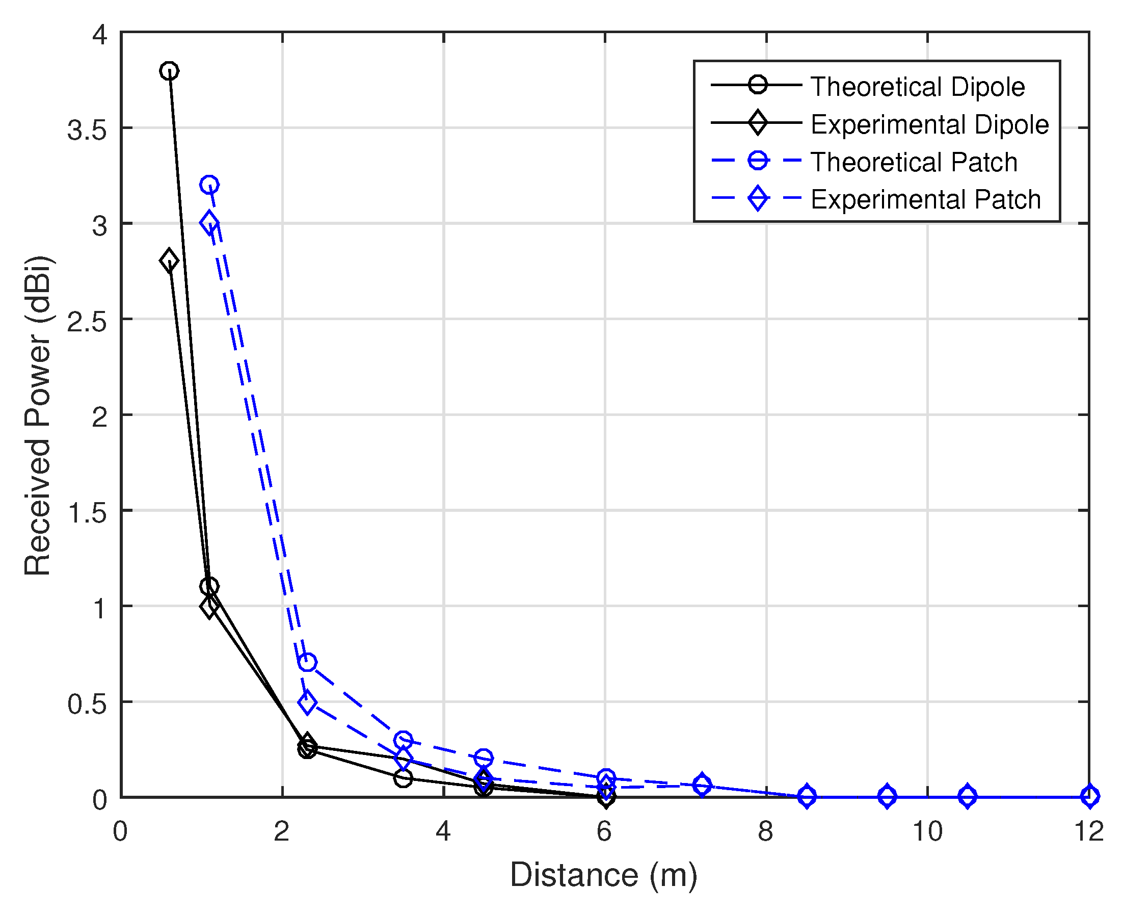
  • Provide a theoretical study on how to estimate the received power in wireless charging taking into consideration the distance between the wireless charging station and the target node, thus identifying the proper wireless energy propagation model. Identifying the proper wireless channel model is important in order to better estimate the amount of the received energy thus estimating the charging time and duration. Furthermore, the attained experimental results are compared with the theoretical results to demonstrate a close match that exists between the two results;
  • The provided theoretical and experimental results assist the researchers and technology adopters to understand the technology, identify its capabilities and limitations while considering it for various applications such as WSN and the IoT;
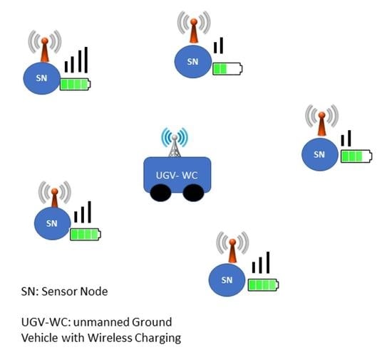
  • The paper introduces a use case for WC in the context of WSN, where the idea of utilizing the CH as a charging node for an unsupervised clustered WSN is proposed. Such a proposition is important due to the CH central location among the other nodes and its prime role in communicating with the other nodes, thus making it the best candidate for providing WC functionality to the sensor nodes.
The rest of the paper is organized as follows: Section 2 presents the related work. The RF-WC technology background and technical details are presented in Section 3. Section 4 presents the experimental setup and the obtained results. Section 5 discusses the experiments’ practical challenges. Section 6 presents a use case for WC in the context of WSN. Finally, Section 7 concludes the paper and proposes future work.

2. Literature Review

In what follows, a literature review for the most related work in the field of RF-based wireless charging and practical implementation and evaluation is presented. The authors in [16] designed such a framework to the point that comprises of a system of sensors outfitted with remote power beneficiaries or receivers, a portable wireless power charger, as well as an energy station that is responsible for observing the energy levels of sensors and consequently choosing the power charging successions at the mobile charger. To be specific, the authors have assembled a proof-of-idea model of the framework and probed the model to assess its plausibility and performance on a small-scale system. Moreover, they have performed broad simulations to consider their proposed framework in large-scale systems and experimentally exhibited that the proposed framework can use the mobile charging innovation successfully to extend the network lifetime. Additionally, they evaluated the impacts of the mobile charging in terms of productivity through simulation by considering different simulation parameters, as well as routing concept, which they believed will become valuable rules at the time the proposed framework is implemented. It is a well-known fact that solar energy harvesting is a widely accepted technique that eases out the deployment of WSNs. However, nodes in WSNs that use batteries employing this technology may suffer at night times or during cloudy periods due to energy shortages arising from the depletion of energy and insufficient solar energy to charge the batteries.
In order to overcome this shortcoming, in [17], the authors have considered the TV broadcast airwaves to power the nodes wirelessly. To be specific, in their contribution, the authors have concentrated on radio frequency as an effective source of ambient energy. Despite the fact that the energy duplicated by encompassing the ambient RF fields is constrained, sensors can be operated over an extensive period of time when broadcast airwaves are utilized. Towards this goal, as a first step, the authors have prototyped a wireless sensor model and realized an adaptive duty cycle assurance technique. With the use of RF energy harvesting, which requires just a rectifier and an antenna as hardware, this model has been found to be highly successful in the detection and transmission of temperature data every 5 s. Besides, the aforementioned energy harvester comprises of only fewer components thereby resulting in low cost and hence, more sensors can be deployed densely. In addition, this harvester is useful in applications that do not call for high power requirement. Recently, due to the fact that RF signal conveys energy and data at the same time, RF energy harvesting is viewed to further advance wireless charging as it is aware of the Simultaneous Wireless Information and Power Transfer (SWIPT). The authors in [18] studied the SWIPT in two-hop Orthogonal Frequency-Division Multiplexing (OFDM) relay systems as it has gained importance as a well-known scheme for wideband digital communication and has been utilized in, for example, 4G mobile communications, DSL Internet access, audio broadcasting, and digital television. In order to address the limits of the OFDM decode-and-forward relay system performance, the authors detailed a Power Allocation (PA) optimization problem to expand its feasible data rate. Not quite same as the related works, in their design of the Resource Allocation (RA) scheme, the Subcarrier Pairing (SP), Power Splitting (PS) factor, and PA at the source and relay are together considered, and the overall energy harvesting at the relay is carried out by taking into account all possible subcarriers, which is then re-designated for the next hop. In addition, since the problem is non-curved and does not have direct solutions, the authors designed an RA approach by treating it as two separate sub-problems. For obtaining the ideal SP, PA, and PS factors, a joint improvement technique was proposed in which the active subcarriers are combined at the relay node as per two hops channel gains. To assess the performance of the system, massive simulation experiments were conducted where the results exhibited that by utilizing their proposed RA approach, maximum feasible data rate of the system can be obtained. However, with similar total accessible power utilization, the SWIPT-empowered OFDM Decode-and-Forward (DF) relay systems have shown some performance impairments compared to the ordinary non-SWIPT OFDM DF relay systems.The authors in [19] introduced an exploratory examination of simultaneous energy and information transmissions in RF-controlled WSNs. In particular, they examined the impact of information transmissions and energy transfer in the same frequency band. In addition, they measured not only the effect of long-extend interference of energy transmitters, but also the energy charging range required to viably revive or recharge nodes. They further demonstrated the interference between RF energy transmitters and wireless nodes when both operate simultaneously in the same spectrum. They likewise distinguished safe frequency detachment for simultaneous information and energy transmission. The destructive interference effect of having various energy transmissions utilizing the same frequency has been also reported. Moreover, the effect of power cancellation on the power harvested has been effectively measured. The practicality and productivity of multi-frequency band RF energy harvesting considering RF energy circuits with a wide response range of frequency have been demonstrated too. In addition, to this end, the authors have exhibited that multi-band RF harvesting and frequency separation are promising for enhancing in general the performance of the system in terms of the throughput.
The authors in [20] summarized many research works, which are based on RF energy harvesting in which the energy limitation of WSNs was addressed using Powercast harvesters. Not only to this extent, but rather they detailed the approach in utilizing ant colony optimization meta-heuristic mechanism. In addition, the authors primarily proposed down-to-earth RF energy harvesting using Powercast harvesters. Furthermore, the harvested and accessible energy of the sensor network’s was managed with an improved energy efficient ant-based routing protocol, which basically helped much in optimizing the available power. Their major goal was to get the sensor networks powered efficiently with/without batteries to keep the network lifetime at the greatest level and avoid any degradation in the network’s performance. In [21], the authors have taken up the problem of individual energy requirement in a sensor network for each of the sensor nodes, and proposed a scheme for optimum charger placements that would lead to a minimum number of chargers, while satisfying the energy requirement of each sensor node. Furthermore, the authors have shown that the problem is NP-hard, and presented two approximation algorithms based on the greedy and relax rounding schemes to achieve better and guaranteed performance in the context of charger placements. Extensive numerical simulations have been conducted to substantiate their claim in terms of the efficacy of the proposed algorithms. A wireless system on chip energy harvesting sources that are capable of harvesting ambient energy has been addressed in [22] along with a power management model that processes and distributes the harvested power using low power radio communication. The basic idea of this work is to present end deployment solutions for energy harvesting. The research work in [23] proposes a new clustering scheme called the Distance Energy Evaluated (DEE) for WSN to increase its lifetime. It has been demonstrated by the authors that DEE has the advantage of utilizing minimum energy for routing and load balancing. In addition, the authors have introduced a layered architecture for topology that supports elasticity in multi-hop communication and adopted unequal size in partitioning the network to form clusters to consume less energy and improve the reliability and lifetime. Mohammad Rahimi et al. [24] have studied the problem of enhancing the lifetime of a WSN by exploiting mobility wherein, a few number of nodes in the network move around in search of energy to recharge and aid the energy depleted stationary nodes to get charged from them. It has been shown through a simple analytical framework that their proposed mobile energy management scheme can improve the network’s lifetime if the total energy utilization rate is less than the rate at which the energy is harvested together with sufficient number of nodes that can move around to support a self-sustaining eco system.
The authors in [25] considered the problem of area charging by designing an efficient charging scheme based on Medial Axis based Charging (MAC) for a Wireless Mobile Charger (WMC). The WMC employed by the authors is directional, which can charge an area that has the shape of a sector. In addition, the WMC is capable of recharging sensors at the boundary of an Area of Interest (AoI). Furthermore, WMC has been designed to recharge any of the sensors inside the AoI with sufficient energy with minimum charging time. In order to deal with area charging, the AoIs are partitioned into rectangular and sector shapes subareas based on the medial axis of the AoIs. The authors proposed a rectangle-based moving approach and rotating approach for the first and second type of partitions, respectively, and calculated the charging time. They evaluated their proposal by conduction extensive simulation trails, and proved that their algorithm achieved a stable approximation ratio. In [26], the authors developed an Energy Stimulated Time Sync (ESTS) method based on a new time synchronization approach to provide ultra-low-power energy harvesting for wireless networks. The ESTS scheme proposed by the authors does not depend on time stamp exchange. However, it employs short radio frequency tones to synchronize energy harvesting nodes with that of the central node. They implemented their proposal on a real Microchip ATmega 256RFR2 System-on-Chip (SoC) and Powercast P1110B radio platform and analyzed its performance with the aid of extensive experiments to demonstrate that their scheme considerably reduces the energy consumption of the energy harvesting nodes than that of the timestamp-based synchronization approaches. Also, they showed that ESTS exhibited an accuracy of 5 ms on an average.
The research in [27] demonstrated with the aid of in-field experimental study on RF wireless charging conducted based on the commercially available transmitters to measure the amount of power obtained from Powercast. The investigation reported by the authors reveal that the power transferred to a few meters of distance employing millimeter-sized antennas with small form factor was from mW to μ W, i.e., at 40 cm distance, the setup is capable of harvesting mill watts of power continuously and for 140 cm up to 592 μ W was harvestable. This range of power was found to be sufficient to charge small IoT devices. Specifically, the authors’ focus was on the Qi- and NFC-aided charging. They performed several experimental evaluations and showed that the RF power transfer is more promising for many of the application scenarios and can charge devices with an obstacle between transmitter and receiver. In addition, their study showed that at 1.6 m distance, an output power 135 μ W and at 1 m distance more than 1 mW was harvested despite the small size of the chip antennas. Furthermore, they advocate that if the impact of obstacles is restricted, RF wireless charging can turn out to be an appealing technology that can be utilized in a wide range of realistic use cases. However, the authors in [28] proposed a self-sustainable WSN energy-proficient architecture which relies on energy harvesting base station mechanism along with a MC with arrangement taken for the cost of deployment. They conducted massive simulations and ultimately demonstrated the effectiveness of their proposed method in the domain that it maximizes the life expectancy of the network, taking the cost of deployment into consideration.
As can be deduced from the conducted literature review, most of the published work focused on integrating and optimizing the wireless charging technology into a specific application of interests. However, our literature review revels a compelling need for providing a detailed study on both the theoretical and technical details of the technology deployment, where the technology capabilities and limitations are examined and discussed. Such a study is of utmost importance for researchers and technology learners who are eager to attain such a knowledge in order to better understand the technology and hence be able to integrate it efficiently into different systems and solutions. Furthermore, the proposed WSN WC integration is very promising and will enhance WSN operation and its lifetime significantly.
To summarize, in what follows, we present in Table 1 the comparison of the contributions provided in our work with that of the closely related literature.

3. Technical Background

Over the years, research on enabling the battery aided electrical devices to consume less power for their operation and making them to be small have called for new sources of energy to recharge the battery. In this context, recently, RF has been viewed as the main source of energy to charge the batteries residing in electrical devices. Consequently, wireless charging has gained widespread research attention both in academia and industry communities. One of the commercially present evaluation kits that allows wireless energy transmission is the Powercast kit. Powercast P2100 uses radio frequency transmission and its transmitter comprises of an oscillator and an antenna, both operating at 915 MHz. The intensity of the wave decreases as a function of distance and as the wave reaches the receiver side it is collected by the antenna and the RF energy is translated to DC power, which is then used to charge the capacitor until a threshold voltage is reached. Following this, the voltage booster and voltage monitor circuits yield an output pulse. The general process of energy harvesting process is depicted in Figure 1 [29].
In order to understand the theoretical background pertaining RF-based wireless charging technology, it is fundamental to realize first how energy is transferred from the transmitter, propagated into the space, and received by the receiving antenna. Therefore, a technical summary about the wave propagation concept is provided. At the transmitter side, considering an isotropic antenna that emits the electromagnetic wave in all directions, the power density measured in W / m 2 ( P d ) at a distance (d) from the radiating antenna is given by Equation (1) [30]:
P d = P t · G t / 4 π · d 2
where P t is the transmitter emitted power, and G t is the antenna transmitter gain. The amount of received power P r d at the receiving antenna with an effective aperture ( A e ) ( m 2 ) is calculated using Equation (2):
P r d = P d · A e .
Then, the received power P r d can be written as shown in Equation (3):
P r d = P t · G t · A e 4 π · d 2 .
Note, that the denominator of Equation (1) represents the area of a sphere of radius d. The receiver antenna A e is related to the antenna receiver gain ( G r ) using Equation (4) [31]:
G r = 4 π · A e ( λ ) 2
where λ is the wavelength of the signal. Therefore, the amount of received (harvested) power ( P r ) at the receiver antenna at distance d from the transmitter can be calculated theoretically by using Equation (5):
P r ( d ) = P r f s ( d ) = P t · G t · G r · λ 2 / ( 4 π · d ) 2 .
This equation represents the simple free space ( P r f s ( d ) ) wave propagation, which is well known as the Friis wireless transmission equation [12]. However, in the real world, the wireless signal is prone to more attenuation due to the surrounding environment, and hence, more advanced models have been proposed in the literature such as the two-ray model [32], where the received power P r n f s is estimated using Equation (6) [32]:
P r n f s ( d ) = P t G t G r h t h r 2 d 4
where h t , h r are the transmitter and receiver antenna heights, respectively. Furthermore, it is important to use the suitable wireless propagation model to estimate the amount of the received energy at the receiver side. To that end, the distance between the wireless charging station and the target node should be estimated and compared with a threshold distance known as the cross over distance ( d c r o s s o v e r ) [33], which will be calculated first using Equation (7), and according to Equation (8), the suitable path loss model is utilized for a certain signal frequency f:
d crossover = 4 π f h t h r λ
P r = P r f s , d < d crossover P r n f s , d d crossover .
In our work, d c r o s s o v e r = 923 meters, where f = 915 MHz and h t = h r = 0.05 meters. Since the distances used in the conducted tests were much lower than the value of d c r o s s o v e r , we adopted the free space wireless channel model for the theoretical analysis, showing a close match with the obtained practical results.

Wireless Charging Implementation Circuit

The purpose behind launching this kit is to allow researchers to evaluate and study the wireless power transfer. It consists of six different components, which include: RF transmitter, energy harvesting receiver boards, patch and dipole antennas, wireless sensor boards, a PIC MCU-based development board, and a programming tool. All the values of the parameters used in the experiments are according to the Powercast kit data sheets [14].
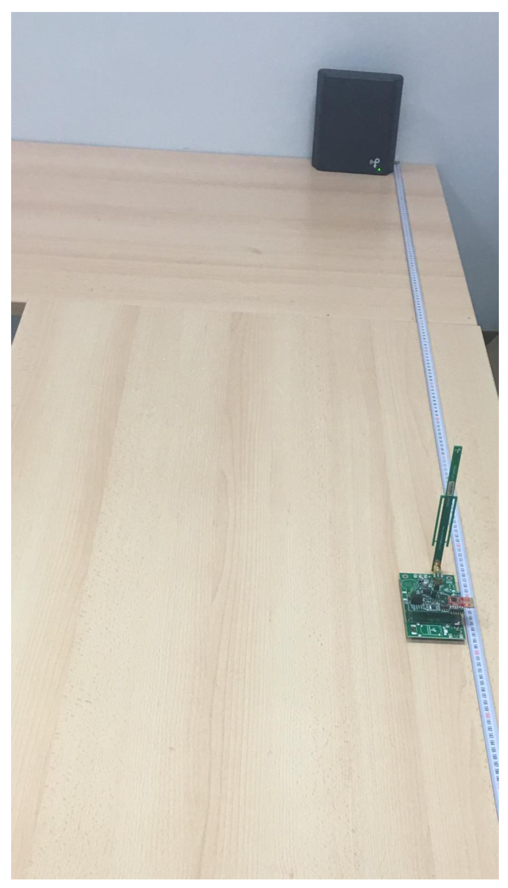
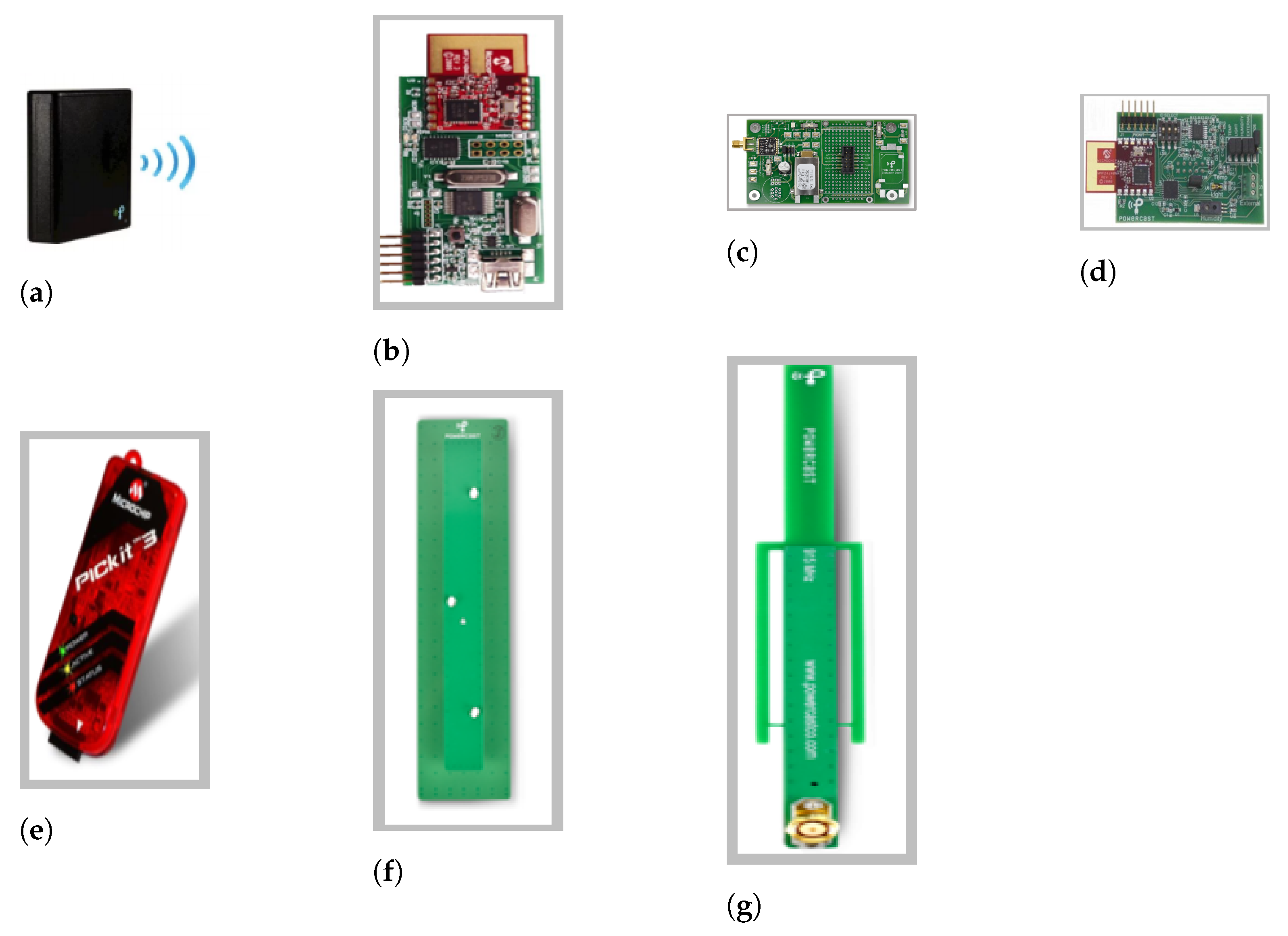
  • Transmitter (TX91501-3W-ID): The transmitter shown in Figure 2a uses the spread spectrum technique to send energy at a frequency of 915 MHz in the Industrial, Scientific, and Medical (ISM) band. The power transmitted is modulated using Direct Sequence Spread spectrum (DSS) which gives the advantage of less interference as we are sending the narrow band on a wider band, which in turn decreases the noise interference. It can move along with the power broadcast, transmit data, which is Amplitude Shift Keying (ASK)-modulated, and sends an 8-bit ID at random intervals at a frequency of 2.4 GHz. There are two different transmitters, one is able to send 1W Equivalent Isotopically Radiated Power (EIRP) and the other one can send 3W EIRP. In this paper, we used the 3W transmitter, which is supported by the utilized kit [14]. EIRP is the maximum power that is radiated from the transmitter in the direction where the antenna exhibits maximum gain in relation to the isotropic antenna. The antenna integrated in the transmitter has a gain of 8 dBi and is 60 degrees beam patterned, and vertically polarized. The transmitter can provide energy for unlimited harvesters;
  • Wireless sensor board (WSN-EVAL-01): This board, which is shown in Figure 2d is able to sense humidity, light, temperature. Furthermore, it gives the option for user to add another sensor-measuring device, which can be connected to the external sensor board found on a terminal block (J3) if needed. The external sensor jack can only supply 3 Volts. The sensor board also has the ability of measuring the Received Signal Strength Indicator (RSSI) of the received power. The sensor information along with the RSSI measurement and node ID of the transmitter that is captured are sent as a packet via a Microchip MiWi P2P low power protocol [34]. The transmission is conducted using a frequency signal centered at 2.4 GHz to the Microchip access point together with the sensor ID that a user can set using the ID selection bits on the sensor board. This information can be viewed on a computer using the hyper terminal utility. The sensor board can be powered using the harvester board if attached on top of the breadboard connection on the harvester board. It has a PIC kit programming header that is used to program the PIC MCU on the sensor board;
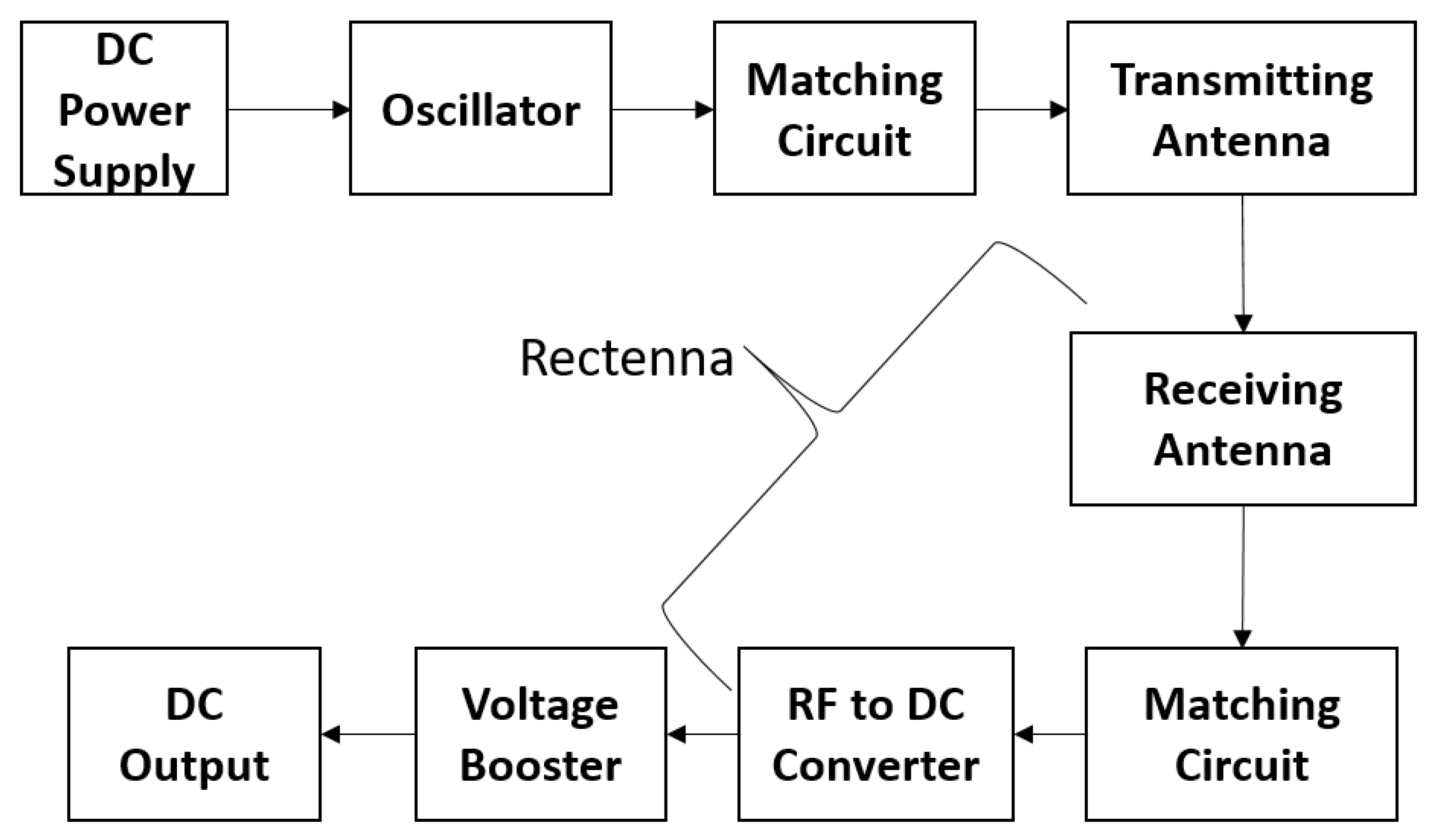
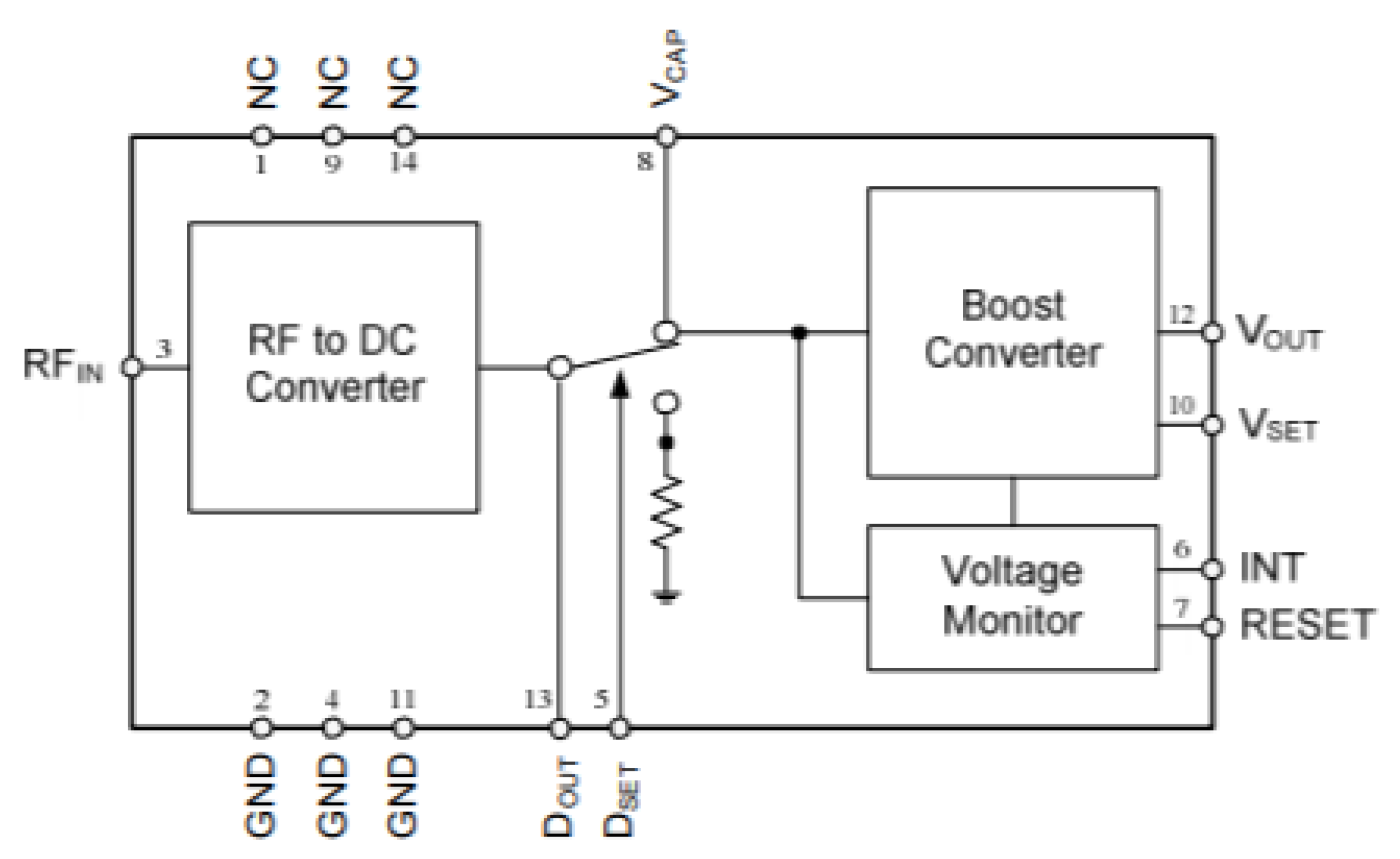
  • Harvester receiver P2110 evaluation board (P2110-EVB): There is an SMA connecter on the harvester board as shown in Figure 2c where the receiving antenna is connected and matched to 50 Ω . As depicted in Figure 3, the receiver board has a P2110 harvester circuit which consists of an RF-DC converter that is implemented using the Microchip pcc110 chip and a voltage booster using the Microchip pcc210 chip. There is also a VCAP pin that can be connected to an external capacitor of the users’ choice or to the capacitors that are already available (C3 of 10mF or C5 of 50 mF). Furthermore, the user can adjust the S2 switch available on the board to either operate the sensor board or use the harvested power to light an LED, which can be easily seen as the LED blinks, or to indicate the arrival of a packet at the access point. As depicted on Figure 3, after the RF signal is received via the antenna and fed to the harvestor RFIN terminal, it is converted to a DC signal via the RF to DC converter circuit, which thereafter can be either stored in the capacitor connected to the pin VCAP (e.g., C3). Obviously, a smaller capacitor will charge much faster than a larger one but can provide power only for a shorter period. Furthermore, when the voltage signal reaches to a threshold value of 1.2 V, the booster circuit generates an output pulse signal around 3.3 V. However, this value can be increased or decreased by attaching an external resistor to the terminal VSET and to the ground as described in the circuit data sheet [35];
  • Dipole and Patch Antennas: Figure 2g shows a dipole antenna with a 360-degree reception range, where as a patch antenna shown in Figure 2f has a 120-degree reception range. Both antennas operate at 915 MHz ISM frequency band. Furthermore, in order to obtain optimal reception, the antennas lengths are designed to have at least half of the utilized wavelength, which equals to 32.76 cm, and normalized 50 Ω impedance. The patch antenna is able to receive more power as it has a gain of 6 dBi, as compared to the dipole antenna that has a gain of 1 dBi.
  • Access point (WSN-AP-01): The Access point in Figure 2b has a USB connection that can be connected to a personal computer (PC) to display the information of the received packets, as well as, the amount of the received power. It also has the capability to receive information from 8 sensor boards. It receives the packets at a frequency of 2.4 GHz that is similar to the one used for radio modules, and displays the information on the PC. It maintains a counter for each of the sensor boards to record the total number of packets received by each sensor board;
  • PICkit 3 programmable debugger (PG164130): The PICKit shown in Figure 2e is used to program the MCU on the sensor board or the access point. The user can update the PICkit tail attached to it and with the help of MPLAB IDE program, the microchip code.

4. Experiment Setup and Results

4.1. Experimental Evaluation

In order to better understand the kit operation, we have conducted a set of experiments. In particular, the setup shown in Figure 4 was used to conduct different experiments. The Powercast transmitter was connected to a voltage supply and placed on a table near its edge in a room facing the harvester. We have considered different distances (in meters) in order to carry out the experiment. Initially, we fixed the harvester at the other end of the setup table. After every test, the receiver was moved to the next distance (towards the transmitter) to redo the test and the process was repeated for different distances as will be depicted later in the paper.
The energy received by the antenna was observed at the beginning on the frequency analyzer MS2720T, which showed two expected peaks, one at 915 MHz, which was used to transmit the RF wave, and the other one at 2.4 GHz, which was used to transmit the data. Furthermore, in order to fully understand the energy charging and harvesting process, several tests with different settings as depicted on Figure 5 were conducted. We observed that on some settings, e.g., Figure 5a,d, the output voltage reached the maximum voltage of 3.3 V, since the wireless charging process was able to harvest enough power required by the booster circuit to generate the maximum possible output pulse signal. Furthermore, it was noticed that this maximum voltage was not obtained on other settings (Figure 5b,c). Therefore, it is important to choose the suitable capacitor and load resistor values to be able to generate the required output voltage signal.

4.2. Measuring the Height and Width of the Pulse for Various Loads

In this section, we present our measurements with respect to the height and width of the pulse. It was observed that the width and height of the pulse vary in accordance with the applied load. To be specific, the width and height of the pulse kept increasing as the load increases. In addition, the current that is available at the output also increases up to a point and starts to fall back. In order to better understand the obtained results, the following points are summarized:
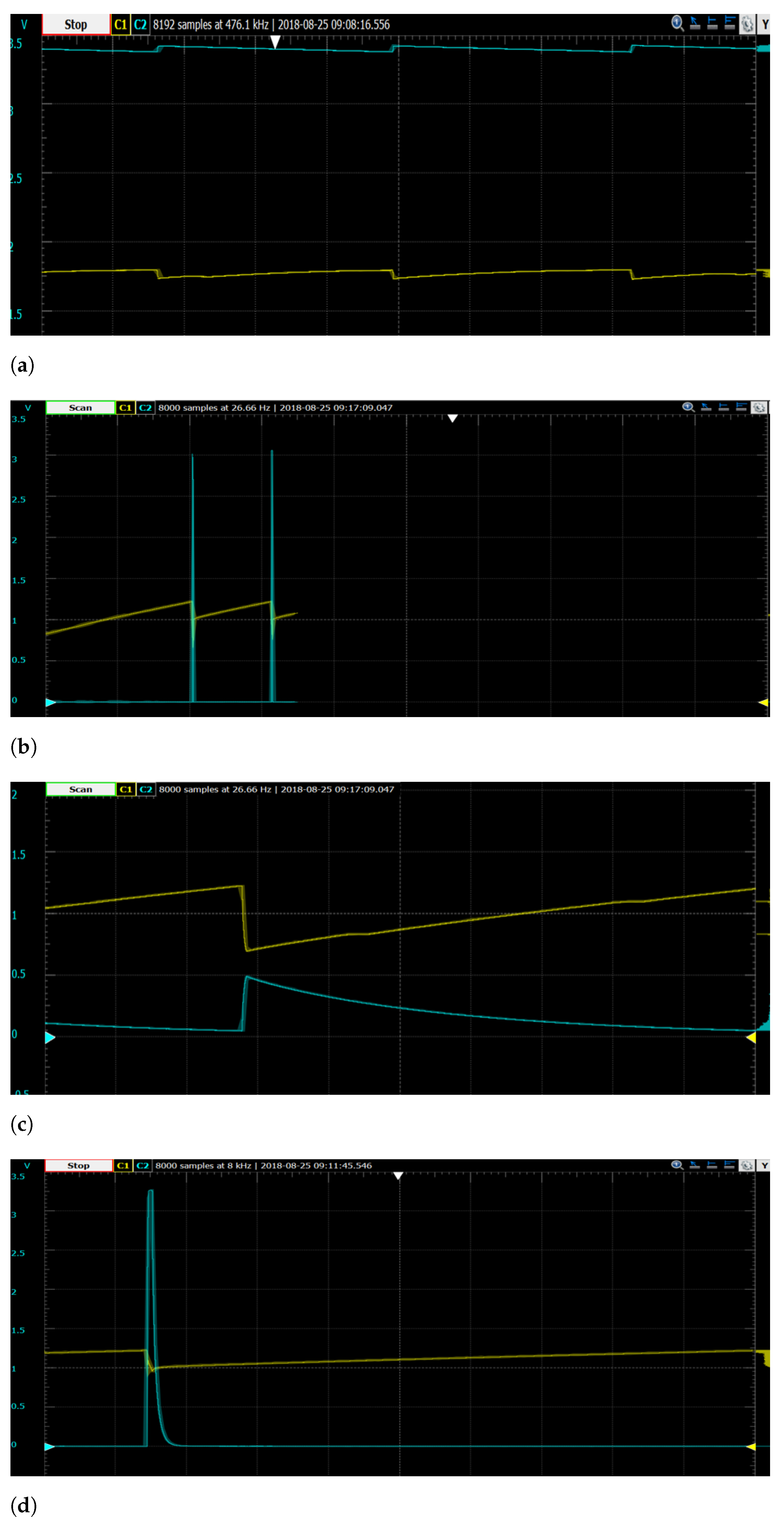
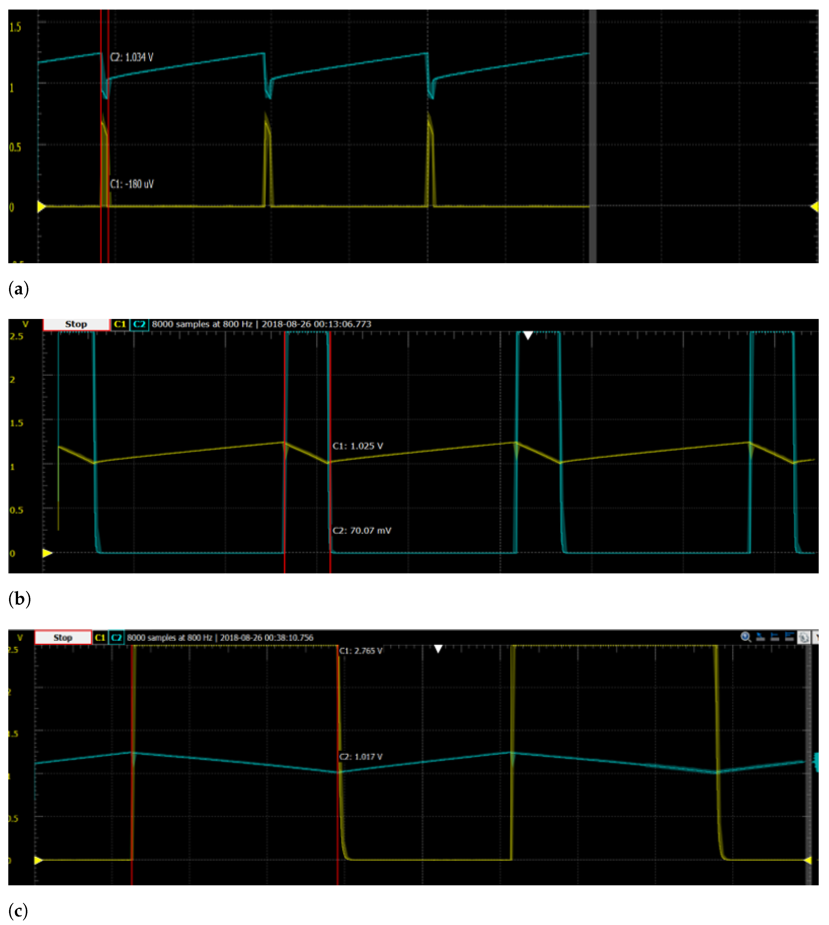
  • As shown in Figure 6 and Figure 7a, when the resistance used is increased, the width of the pulse kept increasing. As seen in Figure 6, there has been an increase from 99.25 ms to 212 ms and to 2.955 s. In this figure, we can also observe that as the pulse is generated, the capacitor voltage (colored in yellow) decreases slowly but the decrease is no more than 0.2 V. Then, the capacitor recharges back again and generates a new pulse. Furthermore, we observed that the time between the pulses remains unchanged when the loads were changed by considering a specific distance (in this case 6 m);
  • As shown in Figure 6a, due to the small Ohmic value of the load, a small amount of power is being used up by the load, and that is the reason for not attaining the maximum voltage, and also, the discharge is noticed to be very minimal. On the other hand, higher voltage values were obtained due to the increased Ohmic value of the load, as can be seen in Figure 6b,c;
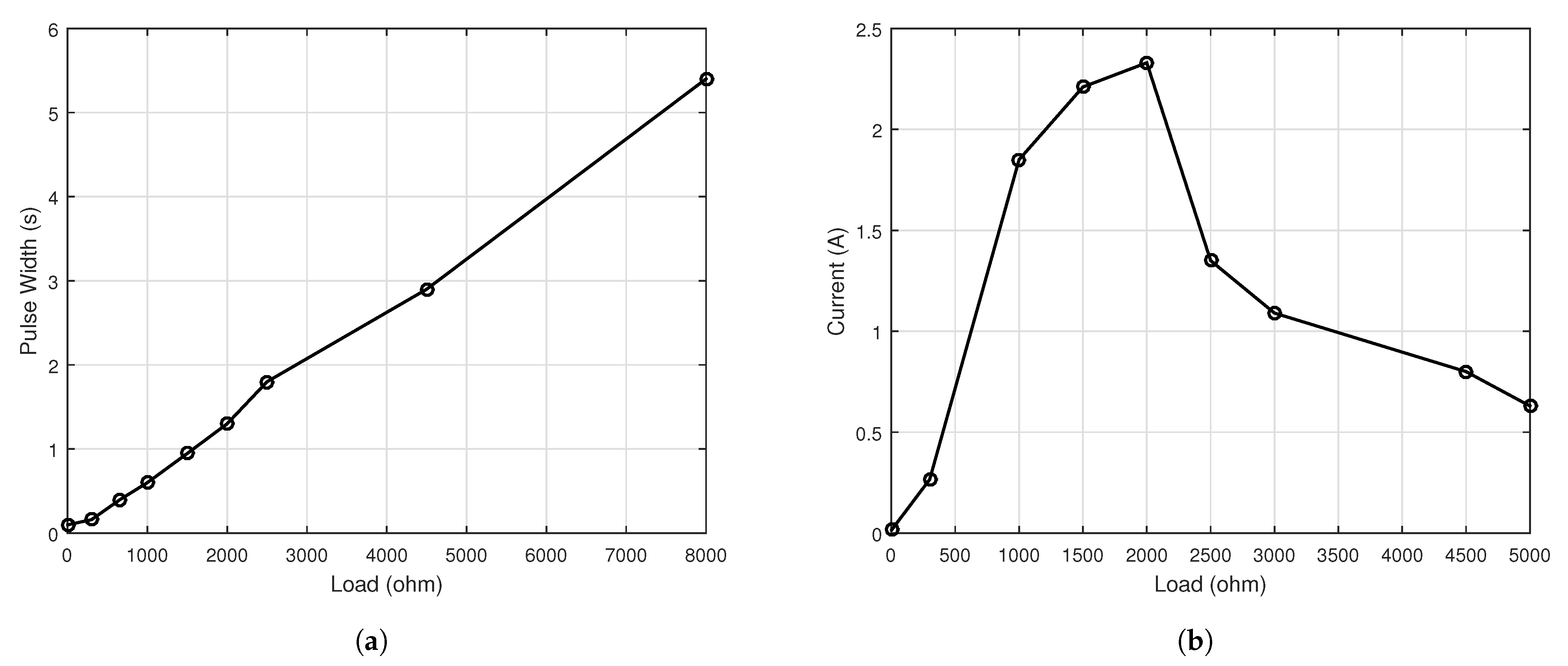
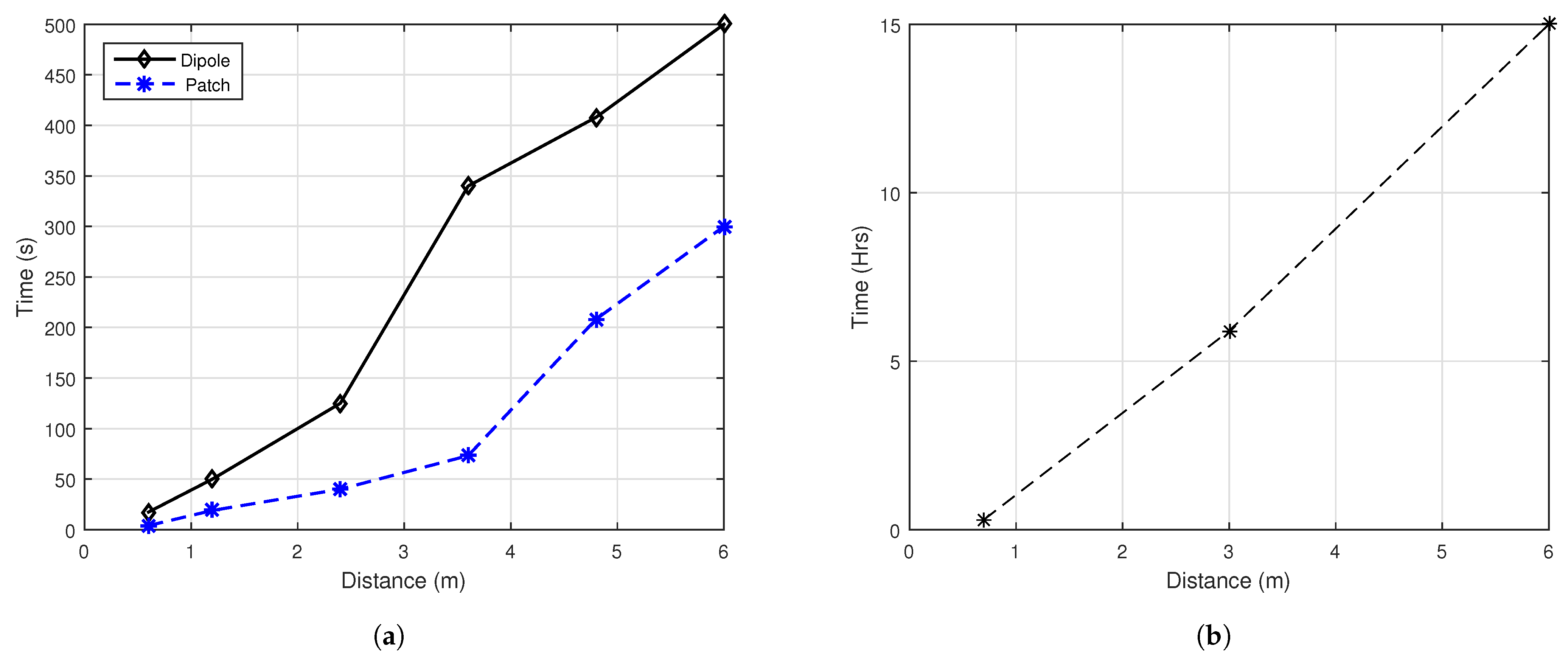
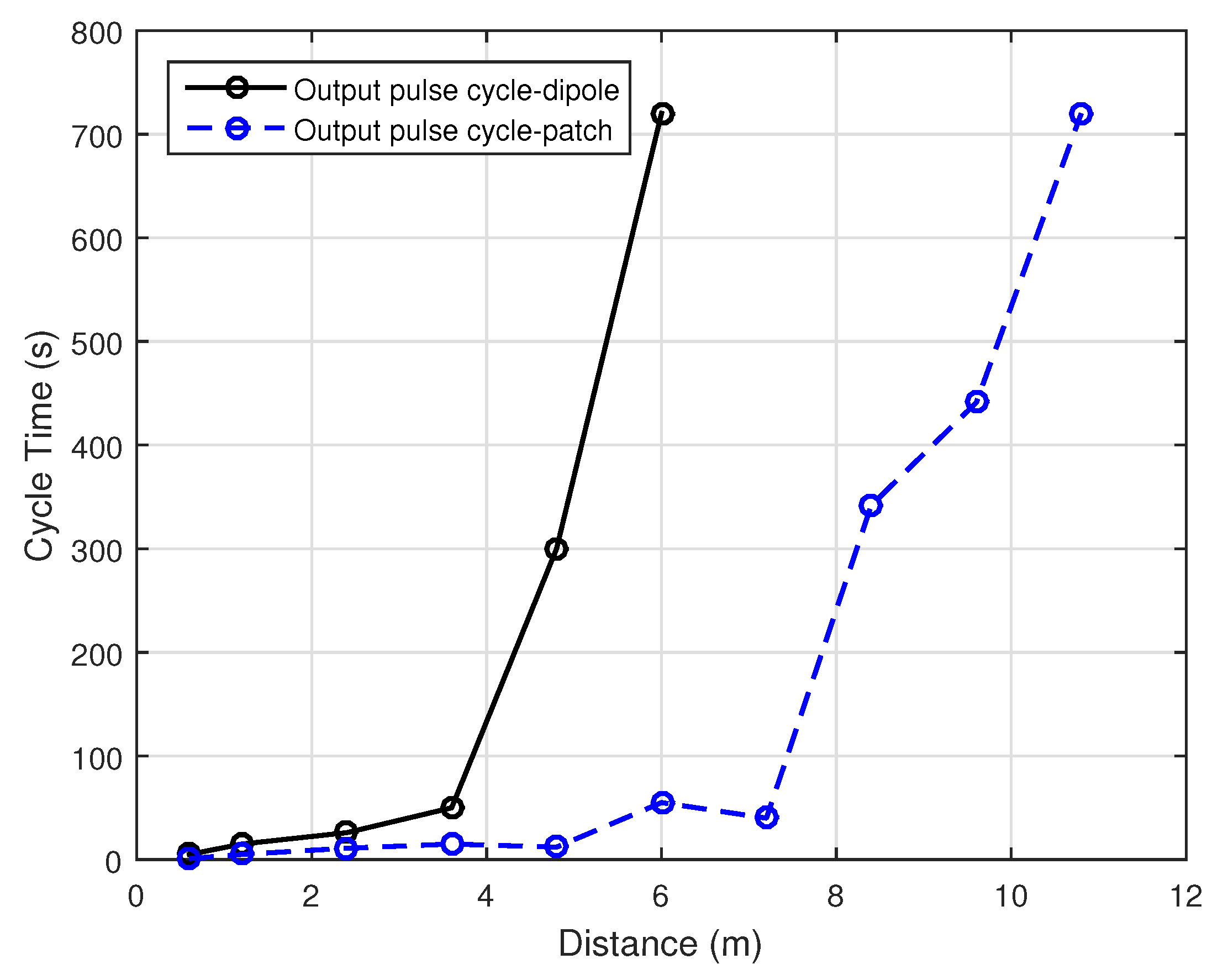
  • The current values versus the load can also be found by either using Ohms law or by measuring it using a current meter, as it is easier to view the current when the width of the pulse increases. Figure 6a,b have been provided as a general case for both antennas considering all the distances from 0.6 to 12 m. It can be noticed from the figures that the charging process exhibits same behavior for all resistance values. However, when the distance increases, the time taken to reach the threshold voltage increases as shown in Figure 8;
  • Furthermore, as depicted in Figure 7b. at the beginning, the power source was able to provide as much voltage as the load required and consequently, the current increased. For 2000 Ω , the power source could no longer provide more voltage, thus the voltage remains constant and the current in the load starts to decrease, since V = I · R , therefore, if V remained constant, and R is increased, then I should decrease. To better understand this phenomena, let us recall the relationship between the charging time T c h needed to charge the capacitor C, and the load resistance R which states that T c h = R · C . Based on this relationship, higher resistance will increase the time taken for the capacitor to charge because of the higher RC time constant. Therefore, the output voltage keeps on increasing until it reaches 3.3 V which is the default maximum voltage for the built-in booster circuit. However, we can suitably adjust the RC constant by adding resistors in order to increase or decrease V s e t ;
  • A linear relationship is seen in Figure 7a between the pulse width and the load value. As the load connected to V o u t increases, the pulse width of V o u t increases proportionately. This is because the V o u t duration depends on the capacitor discharge period. As the discharge time T d i s c h is directly proportional to the product of R and C, (i.e., T d i s c h = R · C ), an increase in R will directly increase T d i s c h . Furthermore, to quantify the measured values, for 1000 Ω load, the width of the pulse is about 0.45 s. For 6000 Ω load, the width of the pulse is 4 s, and with this information, we can approximate any load’s pulse width ( P W ) with the load value R by using the following equation: P W = 0.00071 · R , where 0.00071 is the slope of the linear line between P W and R.

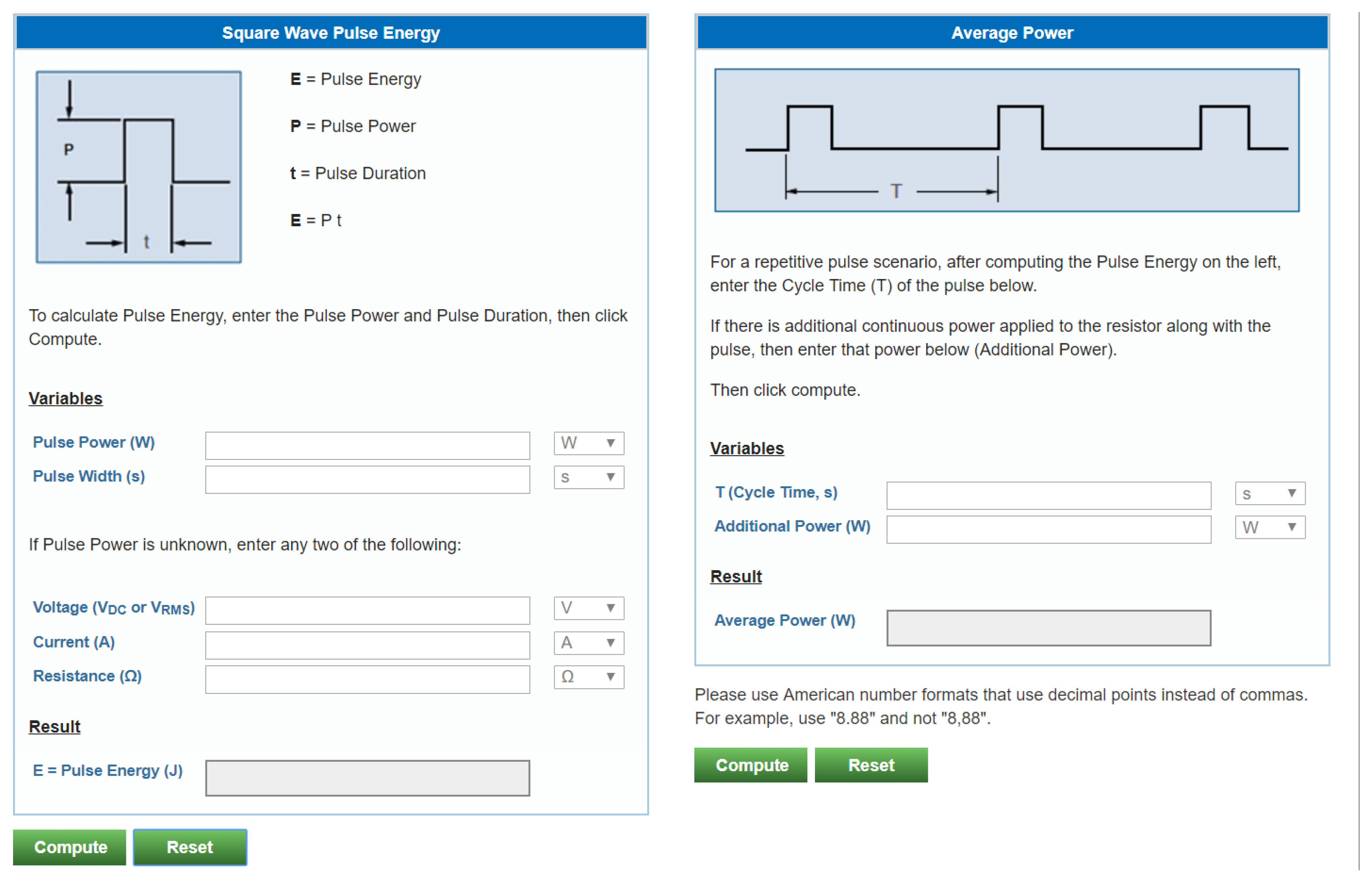
4.3. Measuring the Maximum Average Output Power

Another interesting point is the cycle time of each pulse. As already mentioned, when sufficient energy is presented to the voltage booster, it emits a pulse of 3.3 V. With increasing distance, the intensity of the electromagnetic waves decreases. Consequently, this energy scarcity leads to a longer time in the pulse cycle production. This observation was noticed by measuring the length of each cycle of the pulse. On an average, 4 readings were taken in order to be more accurate, and the outcomes of this experiment is reported in Figure 8.

4.4. The Relationship between the Recharge Time and Distance

With the aid of the previously found information, i.e., the current is maximum with 2000 Ω resistive load, the time of operation is 1.3 s, and the time of each pulse cycle at each of the distances, we could measure the maximum average power of the pulse [36]. In addition, to make sure that the calculated power is maximum, we calculated and averaged it over different resistance values to yield the maximum average power. In order to calculate the average power, we used the equations given below (Equations (9)–(11)), where p, E p , P a v g , T p , and T c are the pulse power, pulse energy, average power, pulse width, and cycle time, respectively:
p = V 2 R
E p = p T p
P a v g = E p T c ·
Furthermore, the online calculator provided by Powercast shown in Figure 9 was used to obtain the theoretical values so that they can be compared with the experimental results. We found that the power received by the patch antenna was more than that of the dipole. Also, as the distance increases, the values measured were found to be remarkably close to the theoretical ones. The theoretical power was calculated using the Friis equation and with the help of the Powercast power calculator.
The transmitter-integrated antenna has a gain of 6 dBi and the receiving antenna could be either of gain 1 dBi or 6 dBi depending on the antenna used. Figure 10 compares the theoretical and experimental results, which shows a close match especially at a large distance.

4.5. Measuring the First Charging Time

The first charging time is also an important metric to be known, since one should have an estimation of how long the process should take from the very beginning, if the capacitor has to be fully discharged before the recharging process can take place. Analog discovery hardware and a waveform software oscilloscope have been used to measure the first charging time. The line that signifies the capacitor’s voltage keeps increasing until it reaches the threshold, which in turn produces the first pulse at Vout and at this point, the threshold value was found to be 1.26 V. The first charging time of the 50 mF has been taken at six different distances and the results are shown in Figure 11a, which demonstrates that the charging time increases as the distance increases.

4.6. Charging 1 F Super Capacitor

To view how the process of charging is happening and if it is possible to actually use it to charge a battery, first, we have carried out the testing using super capacitors. Note, that, the super capacitors are used when the regular electrolytic capacitors are not enough for the application under consideration. Furthermore, super capacitors have been proposed in the literature, for use in wireless sensor nodes [37]. In the conducted experiment, 1F capacitor was used as a reference value. In the context of 1F super capacitor, it took 55 min at a distance of 0.6 m to fully charge when the dipole antenna was used. However, as can be seen from Figure 11b it took 34 min when the patch antenna was utilized. Furthermore, 15 h were needed to fully charge a 1F super capacitor when we employed the patch antenna at a 6 m distance.

5. Practical Challenges and Best Practices

In what follows, a summary of the most important technical challenges encountered while conducting the experiments are provided. Furthermore, our experience and best practices are summarized, which in turn can facilitate the widespread adoption of this new evolving technology in various fields and applications.
  • As explained in Section 3, it is important to determine the suitable path loss model that can be used to estimate the theoretical results for the harvested power, thus being able to predict precisely the amount of harvested energy. This step of utmost importance for charging the nodes in WSN network that can result in improvement in the lifetime of the network;
  • It is advised to follow Electrostatic Discharge (ESD) precautions during the use of the kit, as it is prone to damage from static charges produced by the body. We have used anti-static wrist strap and anti-static mat during the experiments. The devices were not placed on top of the mat while taking measurements as it did affect the readings, yet there is a need to discharge whenever one moves and carries the devices;
  • The kit is sensitive and influenced by the environment too, as any obstacle on the way can affect the radio wave propagation. Furthermore, since the utilized frequency is 915 MHz, it may be interfered by other devices such as mobile phones operating in the same frequency. Thus, several measurements have to be recorded and averaged to get accurate values, which is a time consuming process;
  • Another challenge we encountered was in measuring the current, especially for short distances using the multi-meter. It was not easy as the frequency of the pulsating voltage is high and the width of the pulse is very small.

6. WSN Wireless Charging-Use Case

The main purpose of this section is to demonstrate a use-case scenario for WC in the context of WSN. As previously discussed, SNs are normally distributed on the AoI and grouped into clusters. To achieve this, the Unsupervised Machine Learning K-means algorithm is utilized. The algorithm divides the SNs into K mutually exclusive clusters, such that the nodes that belong to the same cluster are as close as possible to each other, and as far as possible to the other clusters’ nodes. In this work, we used K-means algorithm to cluster the nodes into K clusters, where the centroid of each cluster specifies the location of the WC UGV. However, in order to ensure that the UGV location achieves the maximum energy charging for all the nodes within each cluster, the number of clusters K is chosen such as the nodes’ distances to their cluster centroids are less than a threshold ( α ), where its value is determined from the conducted experiments. For example, in our tests, the time needed to charge a capacitor differed according to the distance and the capacitor capacity. For instance, according to the results depicted in Figure 11, charging a 1F Super capacitor that can be used to charge the SN at a 6 m distance took around 15 h. If such a configuration is suitable for the WSN application under consideration, then α will be set to 6 m, and K will be varied from 1 till K * in a unit step, where K * is the minimum number of clusters considered in order to ensure that all of the distances between all cluster nodes and the centroids is less than α . For example, in Figure 12, we demonstrate how 80 nodes randomly distributed in an AOI were grouped into three clusters K * = 3 using α = 6. Once the number of clusters and their centroids are determined, the UGVs equipped with the wireless charging stations that supports high charging batteries will be sent to the centroids locations of each cluster to mutually collect the sensed data by the sensor nodes and perform the wireless charging process. Furthermore, since the UGV nodes will have two roles (data gathering as a CH and wireless charging station), it is important to ensure that there will be no interference between the signal sent by the SNs to the CHs, and the charging radio signal sent from the CH to the SNs. To achieve this, the SNs as well as the CHs are designed to have two separate radios, one for data transmission and the other one for the wireless charging process. Each radio module operates on different channels, and thus, the interference is avoided.

7. Conclusions and Future Work

In this paper, a study on radio frequency-based wireless charging utilizing off-the-shelf product was provided. In particular, with the aid of the Powercast power charging and harvesting circuit, a set of experiments was conducted to fully understand the technology in terms of the amount of energy received at the charged node, charging time, and charging distance. In addition, the paper provided a theoretical analysis on how to estimate the amount of the energy received for a given distance between the transmitter and receiver. Also, we presented the details on the path loss model to be used based on the crossover distance i.e., to invoke a two-ray path loss model or a Friis model. Accordingly, the amount of energy received was estimated theoretically and compared with the obtained experimental values, which showed a close match between the two results. Moreover, we compared the charging time and distance for the dipole and patch antennas, and the experimental results showed that the later one yielded better performance. Additionally, a use case in the area of WSN was demonstrated, where the sensor nodes were clustered using the Unsupervised Machine Learning K-means algorithm, and the centroid of each of the K-clusters was chosen. An Unmanned Ground Vehicle was used to act as a Cluster Head and wireless charging node to power the nodes within each of the clusters. For future work, we plan to conduct more experiments to take into consideration the potential existence of obstacles between the wireless charging station and wireless nodes. In addition, we are working toward building our own charging system and comparing it with the one used in this study.

Author Contributions

Conceptualization, A.K.; methodology, A.K.; software, A.K.; validation, M.S.; formal analysis, A.K. and K.A.D.; investigation, P.N.; resources, A.K.; data curation, M.S.; writing—original draft preparation, A.K., K.A.D., M.S., P.N.; writing—review and editing, A.K., P.N.; supervision, A.K.; funding acquisition, A.K. All authors have read and agreed to the published version of the manuscript.

Funding

This work is supported by the North Atlantic Treaty Organization (NATO) SPS Project No. SPS G4936, and the German Jordanian University.

Institutional Review Board Statement

Not applicable.

Informed Consent Statement

Not applicable.

Data Availability Statement

Not applicable.

Acknowledgments

The authors would like to thanks Eng. Khaldoun Ayoub for his assistance and efforts.

Conflicts of Interest

Not applicable.

References

  1. Del-Valle-Soto, C.; Velázquez, R.; Valdivia, L.J.; Giannoccaro, N.I.; Visconti, P. An Energy Model Using Sleeping Algorithms for Wireless Sensor Networks under Proactive and Reactive Protocols: A Performance Evaluation. Energies 2020, 13, 3024. [Google Scholar] [CrossRef]
  2. Sakkijha, Z.; Qaderi, H.; Ghatasheh, O.; Issa, A.; Shatat, A.; Jaber, H.; Alwardat, R.; Alhaj-Ali, S. An Energy Efficient WSN Implementation for Monitoring and Critical Event Detection. In Proceedings of the 2019 2nd IEEE Middle East and North Africa COMMunications Conference (MENACOMM), Manama, Bahrain, 19–21 November 2019; pp. 1–6. [Google Scholar]
  3. Khalifeh, A.; Bartolini, N.; Silvestri, S.; Bongiovanni, G.; Al-Assaf, A.; Alwardat, R.; Alhaj-Ali, S. Hybrid wireless sensor networks: A prototype. In Proceedings of the IFIP Conference on Human-Computer Interaction, Bombay, India, 14–18 September 2019; pp. 549–553. [Google Scholar]
  4. Darabkh, K.A.; Wafa’a, K.K.; Ala’F, K. LiM-AHP-GC: Life Time Maximizing based on Analytical Hierarchal Process and Genetic Clustering protocol for the Internet of Things environment. Comput. Netw. 2020, 176, 107257. [Google Scholar] [CrossRef]
  5. Del-Valle-Soto, C.; Mex-Perera, C.; Nolazco-Flores, J.A.; Velázquez, R.; Rossa-Sierra, A. Wireless Sensor Network Energy Model and Its Use in the Optimization of Routing Protocols. Energies 2020, 13, 728. [Google Scholar]
  6. Mohammad, T.; Chih-Min, Y.; Meng-Lin, K.; Kai-Ten, F. On Hybrid Energy Utilization in Wireless Sensor Networks. Energies 2017, 10, 1940. [Google Scholar]
  7. Jain, A.K. Data clustering: 50 years beyond K-means. Pattern Recognit. Lett. 2010, 31, 651–666. [Google Scholar] [CrossRef]
  8. Liu, G.; Mrad, N.; Xiao, G.; Li, Z.; Ban, D. RF-based power transmission for wireless sensors nodes. In Proceedings of the Smart Materials & Structures/NDT in Aerospace/NDT in Canada 2011, Montreal, QC, Canada, 2–4 November 2011. [Google Scholar]
  9. Darabkh, K.A.; Al-Maaitah, N.J.; Jafar, I.F.; Ala’F, K. EA-CRP: A Novel Energy-aware Clustering and Routing Protocol in Wireless Sensor Networks. Comput. Electr. Eng. 2017, 72, 702–718. [Google Scholar] [CrossRef]
  10. Al-Agtash, S.; Tanash, R.; AlQudah, M. Deploying agents for monitoring and notification of wireless sensor networks. In Proceedings of the 2016 IEEE 28th International Conference on Tools with Artificial Intelligence (ICTAI), San Jose, CA, USA, 6–8 November 2016; pp. 754–757.
  11. Penella, M.; Gasulla, M. A review of commercial energy harvesters for autonomous sensors. In Proceedings of the Instrumentation and Measurement Technology Conference Proceedings, Warsaw, Poland, 1–3 May 2007; pp. 1–5. [Google Scholar]
  12. Agbinya, J.I. Wireless Power Transfer; River Publishers Series in Communications; River Publishers: Aalborg, Denmark, 2015; Volume 45. [Google Scholar]
  13. Lu, X.; Wang, P.; Niyato, D.; Kim, D.I.; Han, Z. Wireless charging technologies: Fundamentals, standards, and network applications. IEEE Commun. Surv. Tutor. 2015, 18, 1413–1452. [Google Scholar] [CrossRef] [Green Version]
  14. Powercast Inc. Site. Available online: https://www.powercastco.com/documentation (accessed on 24 March 2020).
  15. Saadeh, M.; Darabkh, K.A.; Nagaradjane, P. Radio-Frequency Based Energy Charging-An Experimental Study. In Proceedings of the 2019 2nd IEEE Middle East and North Africa COMMunications Conference (MENACOMM), Manama, Bahrain, 19–21 November 2019; pp. 1–4. [Google Scholar]
  16. Peng, Y.; Li, Z.; Zhang, W.; Qiao, D. Prolonging sensor network lifetime through wireless charging. In Proceedings of the 2010 31st IEEE Real-Time Systems Symposium, San Diego, CA, USA, 30 November–3 December 2010; pp. 129–139. [Google Scholar]
  17. Nishimoto, H.; Kawahara, Y.; Asami, T. Prototype implementation of ambient RF energy harvesting wireless sensor networks. In Proceedings of the Sensors, Waikoloa, HI, USA, 1–4 November 2010; pp. 1282–1287. [Google Scholar]
  18. Di, X.; Xiong, K.; Zhang, Y.; Qiu, Z. Simultaneous Wireless Information and Power Transfer in Two-hop OFDM Decode-and-Forward Relay Networks. TIIS 2016, 10, 152–167. [Google Scholar]
  19. Naderi, M.Y.; Chowdhury, K.R.; Basagni, S.; Heinzelman, W.; De, S.; Jana, S. Experimental study of concurrent data and wireless energy transfer for sensor networks. In Proceedings of the Global Communications Conference (GLOBECOM), Austin, TX, USA, 8–12 December 2014; pp. 2543–2549. [Google Scholar]
  20. Zungeru, A.M.; Ang, L.M.; Prabaharan, S.; Seng, K.P. Radio frequency energy harvesting and management for wireless sensor networks. In Green Mobile Devices and Networks: Energy Optimization and Scavenging Techniques; CRC Press, Taylor and Francis Group: Boca Raton, FL, USA, 2012; pp. 341–368. [Google Scholar]
  21. Xingjian, D.; Jianxiong, G.; Deying, L.; Ding-Zhu, D. Minimum wireless charger placement with individual energy requirement. In Proceedings of the International Conference on Combinatorial Optimization and Applications, Dallas, TX, USA, 11–13 December 2020. [Google Scholar]
  22. Abhay, J.; Sai, D.M.; Hara, G.M.P. Analysis of energy harvesting techniques for wireless sensor networks deployment scenarios. In Proceedings of the International Conference on IoT and its Applications, Jamshedpur, India, 25–27 December 2017. [Google Scholar]
  23. Salim El, K.; Nejah, N.; Rehan Ullah, K.; Abdennaceur, K. An improved energy efficient clustering protocol for increasing the life time of wireless sensor networks. Wirel. Pers. Commun. 2021, 116, 539–558. [Google Scholar]
  24. Rahimi, M.; Shah, H.; Sukhatme, G.S.; Heideman, J.; Estrin, D. Studying the feasibility of energy harvesting in a mobile sensor network. In Proceedings of the 2003 IEEE International Conference on Robotics and Automation, Taipei, Taiwan, 14–19 September 2003. [Google Scholar]
  25. Dai, H.; Wang, X.; Xu, L.; Dong, C.; Liu, Q.; Meng, L.; Chen, G. Area charging for wireless rechargeable sensors. In Proceedings of the 2020 29th International Conference on Computer Communications and Networks (ICCCN), Honolulu, HI, USA, 3–6 August 2020; pp. 1–9. [Google Scholar]
  26. Luo, Y.; Pu, L. ESTS: Energy Stimulated Time Synchronization for Energy Harvesting Wireless Networks. In Proceedings of the GLOBECOM 2020-2020 IEEE Global Communications Conference, Taipei, Taiwan, 7–11 December 2020; pp. 1–6. [Google Scholar]
  27. Meile, L.; Ulrich, A.; Mayer, P.; Magno, M. Radio Frequency Power Transmission for Self-Sustaining Miniaturized IoT Devices: Survey and Experimental Evaluation. In Proceedings of the 2020 International Symposium on Power Electronics, Electrical Drives, Automation and Motion (SPEEDAM), Sorrento, Italy, 24–26 June 2020; pp. 132–137. [Google Scholar]
  28. Abid, K.; Jaber, G.; Lakhlef, H.; Lounis, A.; Bouabdallah, A. An Energy Efficient Architecture of self-sustainable WSN based on Energy Harvesting and Wireless Charging with Consideration of Deployment Cost. In Proceedings of the 16th ACM Symposium on QoS and Security for Wireless and Mobile Networks, Alicante, Spain, 16–20 November 2020; pp. 109–114. [Google Scholar]
  29. Wireless RF Energy Harvesting: RF-to-DC Conversion, Powercast Hardware Datasheet. Available online: https://www.allaboutcircuits.com/technical-articles/wireless-rf-energy-harvesting-rf-to-dc-conversion-powercast-hardware (accessed on 24 March 2020).
  30. Haslett, C. Essentials of Radio Wave Propagation; Cambridge University Press: Cambridge, UK, 2008; Volume 91. [Google Scholar]
  31. Balanis, C.A. Antenna Theory: Analysis and Design; John Wiley & Sons: Hoboken, NJ, USA, 2016. [Google Scholar]
  32. Rappaport, T.S. Wireless Communications: Principles and Practice; Prentice Hall PTR: Englewood Cliffs, NJ, USA, 1996; Volume 2. [Google Scholar]
  33. Darabkh, K.A.; Ismail, S.S.; Al-Shurman, M.; Jafar, I.F.; Alkhader, E.; Al-Mistarihi, M.F. Performance evaluation of selective and adaptive heads clustering algorithms over wireless sensor networks. J. Netw. Comput. Appl. 2012, 35, 2068–2080. [Google Scholar] [CrossRef]
  34. Yang, Y. Microchip MiWi™ P2P Wireless Protocol. Microchip Appl. Note AN1204. ix 2010, 52, 53. [Google Scholar]
  35. Powercast P2110 Harvestor Circuit Datasheet. Available online: https://www.powercastco.com/wp-content/uploads/2016/12/P2110B-Datasheet-Rev-3.pdf (accessed on 24 March 2021).
  36. Valenta, C.R.; Durgin, G.D. Harvesting wireless power: Survey of energy-harvester conversion efficiency in far-field, wireless power transfer systems. IEEE Microw. Mag. 2014, 15, 108–120. [Google Scholar]
  37. Simjee, F.; Chou, P.H. Everlast: Long-life, supercapacitor-operated wireless sensor node. In Proceedings of the 2006 International Symposium on Low Power Electronics and Design, Tegernsee, Germany, 4–6 October 2006; pp. 197–202. [Google Scholar]
Figure 1. Energy harvesting process simplified.
Energies 14 01829 g001
Figure 2. Powercast Kit components consist of: (a) TX91501-3W Transmitter; (b) access point WSN-AP-01; (c) harvester P2110-EVB; (d) wireless sensor board WSN-EVAL-01; (e) pickit-3; (f) patch antenna and (g) dipole antenna.
Energies 14 01829 g002
Figure 3. P2110 harvestor circuit block diagram [35].
Energies 14 01829 g003
Figure 4. Experiment setup.
Energies 14 01829 g004
Figure 5. (a) Testing without a load and capacitor; (b) Testing without a capacitor and with a 660 Ω load; (c) Testing with the on board capacitor C3 capacitor and a 660 Ω load; (d) Testing with the on board C5 capacitor and with a 660- Ω load.
Energies 14 01829 g005
Figure 6. Length of the Pulse using: (a) 10 Ω (b) 660 Ω , and (c) 3 K Ω .
Energies 14 01829 g006
Figure 7. The relation between the pulse width, (a) load current and (b) load.
Energies 14 01829 g007
Figure 8. Charging time vs distance.
Energies 14 01829 g008
Figure 9. Powercast online calculator.
Energies 14 01829 g009
Figure 10. The theoretical versus practical power results for different distances.
Energies 14 01829 g010
Figure 11. First charging time: (a) for the c5 built in capacitor (50 mF); (b) Charging 1F capacitor using patch antenna.
Energies 14 01829 g011
Figure 12. A total of 80 sensor nodes clustered into 3 clusters according to the K means algorithm, the centroids represent the locations of the UGVs with holding the wireless charging stations.
Energies 14 01829 g012
Table 1. Comparison of our work with other closely related works. Wireless Charging (WC); Unmanned Ground Vehicle (UGV); Wireless Sensor Networks (WSNs); and Cluster Head (CH).
Comparison
The Utilization for Off-the-Shelf WC ProductsApproachCluster Head for WCUGV as CHProsCons
Peng, Y et al. [16]NoExperimentalNoNoTolerant to localization inaccuracyExponential complexity
Naderi, M.Y. et al. [19]NoExperimentalNoNoMulti-frequency band RFenergy harvestingSmall size indoor WSN
Zungeru, A.M. et al. [20]YesExperimentalNoNoEnergy managementLacks linking circuit for direct charging
Salim El, K et al. [23]NoSimulationYesNoImproved Life span and energy usageLacks of experimental study
Dai, H. et al. [25]NoTheoretical and SimulationNoNoImproved charging timeLacks of experimental study
Meile, L. et al. [27]YesExperimentalNoNoSmall form factor antennasLimited obstacles
Our workYesExperimental and theoreticalYesYesPractical insight for WC technology adoptionLacks of obstacles between the transmitter and receiver
Publisher’s Note: MDPI stays neutral with regard to jurisdictional claims in published maps and institutional affiliations.

