Abstract
This paper proposes an adaptive fault tolerant control (FTC) design for a variable speed wind turbine (WT) operating in the high wind speeds region. It aims at mitigating pitch actuator faults and regulating the generator power to its rated value, thereby reducing the mechanical stress in the high wind speeds region. The proposed FTC design implements a sliding mode control (SMC) approach with an adaptation law that estimates the upper bounds of the uncertainties. System stability and uniform boundedness of the outputs was proven using the Lyapunov stability theory. The proposed approach was validated on a 5 MW three-blade wind turbine modeled using the National Renewable Energy Laboratory’s (NREL) Fatigue, Aerodynamics, Structures and Turbulence (FAST) wind turbine simulator. The controller’s performance was assessed in the presence of several pitch actuator faults and turbulent wind conditions. Its performance was also compared to that of a standard SMC approach. Mitigation of blade pitch actuator faults, generation of uniform power, smoother pitching actions and reduced chattering compared to standard SMC approach are among the main features of the proposed design.
1. Introduction
Wind energy is among the most promising and fastest growing sustainable energy source. The global cumulative installed capacity of wind turbines is expected to reach 817 GW by the end of 2021 [1]. However, wind turbines’ inherent nonlinear dynamics along with their operation in the presence of highly complex loads make their control a challenging problem [2]. Additionally, the control objective and wind turbine operation vary depending on the wind speed region. For wind speeds below the rated speed, wind turbines are operated to maximize the captured power by regulating the generator load torque. Whereas, in the high wind speed region, wind turbines (WTs) are operated to maintain the generated power at its nominal value by controlling the pitch angle and the generator torque. Designs such as proportional integral derivative (PID) control [3], neural network based-PI control [4], optimal control [5], linear parameter varying (LPV) control [6], gain scheduling [7], robust control [8], adaptive control [9] and fuzzy logic control [10] have traditionally been considered to control wind turbines. However, these solutions fail to operate satisfactorily and exhibit limited control action in the presence of faults. Additionally, blade pitch actuator faults slow down the dynamic response of the pitch angle and result in fluctuations in the output power and the generator’s speed. Designing advanced controls that are capable of properly mitigating the effects of such faults can lead to improved power quality and reduced maintenance cost and downtime, especially for offshore wind turbines.
Fault tolerant controls (FTCs) are control systems that are able to maintain satisfactory performance under faulty conditions and prevent faults from evolving into failures that might jeopardize system safety and reliability [11]. FTC approaches are generally classified into active and passive schemes. Active FTCs require a fault detection and identification (FDI) unit to explicitly detect and estimate the faults, whereas passive FTCs rely solely on the use of robust controls to ensure system insensitivity to certain faults without such explicit detection. A number of FTC methods have been developed for the pitch angle control of wind turbines. A model-based fault-tolerant pitch control approach was proposed in [12] for an offshore wind turbine. An adaptive sliding mode estimation-based fault tolerant wind turbine pitch control was proposed in [13]. An active FTC approach consisting of an FDI and a control reconfiguration (CR) module was proposed in [14] for the pitch and converter sub-systems of a 2MW wind turbine. The CR module was developed based on the model-predictive control (MPC) approach, whereas the Faull Detection and Diagnosis (FDD) module considered an input residual generator and an estimation filter to properly detect fault information. An active fault tolerant control combining a fuzzy gain scheduling-based proportional-integral (PI) control with a signal correction algorithm was proposed in [15] to accommodate WT’s sensor faults. A fault detection approach consisting of an observer combined with a residual signal generator was proposed in [16] for a wind system in the microgrid. An adaptive output feedback approach implementing an output feedback and a full-order compensator for fault and disturbance attenuation was proposed in [17]. The controller parameters were adjusted using a linear matrix inequality (LMI) technique. Though the approach was able to maintain the rotor speed and generated power quality, its complexity and computational cost can hinder its practical implementation. A passive FTC strategy was proposed in [18] to mitigate fault-induced saturations in a WT. It is worth noting, however, that active FTC approaches are complex and computational expensive, whereas passive approaches are conservative and can only accommodate faults that were known a priori and considered at the design stage [19].
Sliding mode control (SMC) is one of the most effective control designs for nonlinear uncertain systems [20]. The main objective of the design procedure is to enforce the trajectories of the closed-loop system to belong to a prescribed manifold or sliding surface constructed a priori to ensure the error asymptotically approaches zero in a sliding mode [21]. Attributes such as limited variance to external disturbances, robustness to parameter variations and ease of implementation with power electronics have led to wide adoption in WT control [22]. A standard SMC approach was proposed in [23] to control the blade pitch angle of a wind turbine. A robust sliding mode approach was prosed in [24] for rotor speed regulation in the presence of uncertainties and disturbances. An SMC-based approach with coefficients that have been computed via the particle swarm optimization support vector machine method was proposed in [25]. The obtained results showed that, in the presence of disturbances, the proposed design achieved better performance than the model reference adaptive control (MRAC). However, no faults were considered at the design stage. A sliding mode observer-based approach was proposed in [26] to achieve multiple fault reconstruction for a wind turbine subject to simultaneous actuator and sensor faults.
Among the shortcomings of standard SMC are its inability to guarantee the finite time convergence of the systems states and the chattering phenomena. This latter can result in lowering the accuracy of the control, mechanical wear and high heat losses [27]. Substituting the linear sliding variable in standard SMC for a nonlinear counterpart was shown to yield finite time convergence [28,29], whereas integral terminal SMC approaches were shown to mitigate the chattering problem [30]. An Integral Terminal Sliding Mode (ITSMC) approach, with gains auto-tuned using a fuzzy system, was proposed in [31] for DFIG-WT. Though it improved the wind turbine’s performance in the presence of faults and disturbances, its implementation was computationally challenging. Chattering can also be effectively and simply mitigated by reducing the magnitude of the discontinuous component. This can be done by incorporating an adaptation mechanism in the SMC approach as shown in [32].
This paper designs and implements a robust adaptive fault tolerant control approach to mitigate wind turbines’ pitch actuator faults. The main contributions of this paper are as follows:
- An adaptive sliding mode control (ASMC) approach capable of mitigating pitch actuator faults whilst ensuring system stability under faulty conditions,
- An adaptation mechanism resulting in a sliding mode approach with reduced gain compared to existing approaches [33] thereby minimizing the chattering problem,
- A fault tolerant control approach that does not require any explicit information from the fault detection unit, hence resulting in a simple and easy to implement FTC design.
The remainder the paper is organized as follows. Section 2 outlines the WT’s operation and model. Section 3 derives the control approach and provides its stability analysis based on Lyapunov theory. Section 4 illustrates the performance of the proposed approach. A comparison to another SMC approach is also carried out in this section. The conclusion is finally given in Section 5.
2. Wind Turbines’ Operation and Modeling
To determine the required control strategy and ensure that the WT’s structural health is maintained, the relationship between power and wind speed should be taken into consideration. This relationship is typically illustrated using the ideal power curve depicted in Figure 1. Here the cut-in and cut-out speeds are the operating limits of the WT. Maintaining the turbine within this range ensures that the available energy is above the minimum threshold and structural health is maintained.
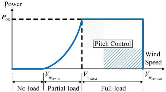
Figure 1.
Ideal wind turbine (WT) power curve [34].
As shown in Figure 1, the ideal operation of wind turbines can be categorized in two regions: partial and full load. In the partial-load region, the WT can produce an optimum amount of power using a torque control, while in the full-load region the wind is operated above its rated value. Thus, in this region, the power is kept constant and pitch control is considered to alleviate the mechanical stress while generating the rated electrical power.
Figure 2 illustrates the structure of a WT deploying pitch and torque controls.
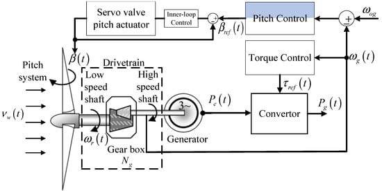
Figure 2.
Schematic of a WT with pitch and torque controls.
Since the focus of our design is on variable WTs operating in the high wind speeds region, we briefly describe in what follows the dynamic model of the WT in the full-load region.
2.1. WT’s Aerodynamic Model
The power captured by the rotor can be described by [34,35,36,37]:
Neglecting the variations of the torque with respect to the rotor speed and linearizing (1) using the first-order Taylor series yields:
where is the partial derivative of the power with respect to .
2.2. Drivetrain Model
The drivetrain can be modeled by [37]:
Maintaining the power constant, in the full-load region, yields the following generator torque:
Linearizing (4) using the first-order Taylor series yields:
Substituting (2) and (5) into (3) yields:
Using the torsion angle equation to represent the generator speed with respect to the rotor speed, yields [37].
Assuming the drivetrain to be in steady state i.e., and neglecting initial conditions, yields:
Substituting (8) into (6) yields:
2.3. Pitch Actuator Model
Each of the three pitch actuators of the pitch system can be modeled as a piston servo system that can be modeled as a closed loop transfer function between the pitch angle β and its reference value βref [38], as follows:
where, ξ is the damping factor and ωn is the natural frequency.
It is worth noting that, though all WT components may be subject to faults and failures, the frequency of their occurrence as well as their severity differ. Based on the study reported in the ReliaWind project [35], faulty pitch conditions are the leading cause in WT faults and downtime. Those faults can range from pitch sensor faults being stuck at a fixed value, to a scaling fault resulting from calibration errors in the position sensor, to parameter changes in the hydraulic pitch system resulting from incipient faults caused by high air content in the hydraulic cylinder or a sudden drop in the oil pressure [36]. If not properly mitigated, pitch actuator faults slow down the dynamic response of the pitch angle and lead to fault induced fluctuations in the generator speed, torque and output power. Under severe conditions, they can lead to failures and WT downtimes.
3. Controller Design
To properly mitigate pitch actuator faults, this paper proposes an adaptive SMC-based FTC design derived as follows.
Differentiating (9) twice and considering the error yields:
Substituting and by their expressions, yields:
It what follows, for the sake of simplicity, notational dependencies will be omitted on , , , , ,, , s.
Defining the following sliding surface:
where .
Differentiating (13) and substituting by its value yields:
where . Assuming the power sensitivity to be uncertain and expressed as , where is the power sensitivity around an operating point, and is an unknown but bounded perturbation term such that: and substituting this expression into (14), yields:
Defining , , , and substituting those expressions in (18) yields:
The pitching control law is derived by first computing the equivalent control , which is obtained when and , and synthesizing the adaptive SMC according to the steps below. The overall control is given by:
where is the equivalent control pitch input as follows:.
is given by:
where , and are respectively the adaptive and switching terms of the adaptive SMC control. and are adaptive gains expressed as follows:
where , , are positive constants.
The following assumptions are considered [32]:
Assumption 1.
The functionis norm bounded, with
Assumption 2.
The unknown termis norm bounded, with.
Assumption 3.
The termis norm bounded, with.
In what follows, we will prove that considering the control law (21) with the adaptive law (22) will yield a closed-loop system with output signals that are uniformly bounded.
Substituting (20) and (19) into (18) yields:
Substituting by, as per assumption 1, and considering . yields:
Substituting (21) into (24) yields:
For convenience, let us define:
The sign function can be approximated as follows: [32] where is a very small value. Considering , and substituting the sign function by its approximation for in (26) yields:
Assuming the function to be bounded such that:
where is unknown, we can re-write (27) as follows:
According to assumption 3 and equation (28) and can be expressed as follows:
where , and are bounded functions such that , . (29) can be rewritten as follows:
Consider the following Lyapunov function:
where is the parameter adaptation error such that, , a positive-definite matrix, with where , , and .
Computing the first derivative of (32) yields:
Such that:
where the matrix is positive-definite, provided the following inequalities are held [32]:
Developing (33) yields:
Since, , then:
Considering , (36) can be re-written as:
Considering , (22) can be expressed as follows:
Hence, (38) can be re-written as follows:
Substituting the adaptive law (22) into (40), yields:
Since , then thus confirming the uniform boundedness of all the output signals and therefore the finite time stability of the system.
Remark: It is worth noting that in this work we have opted for a quadratic Lyapunov function. However, one can also select a non-quadratic Lyapunov function, which was shown in [39] to yield better performance.
4. Simulation Results
The proposed controller was validated using a comprehensive simulation study on a 5 MW three-blade wind turbine modeled using the National Renewable Energy Laboratory (NREL) wind turbine Fatigue, Aerodynamics, Structures and Turbulence (FAST) simulator [40]. The wind inputs were generated using Turbsim software [41]. The experiments were carried out for a wind profile with average speeds of 12 and a turbulence intensity of 6 as illustrated in Figure 3a. The WT’s parameters are provided in Table A1.
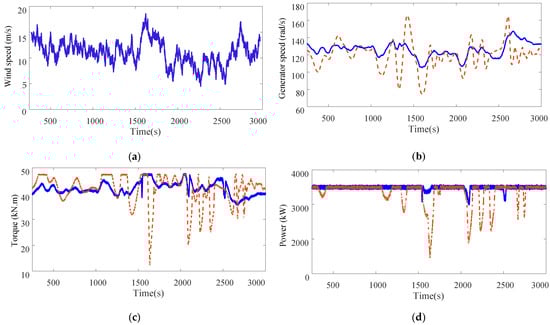
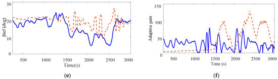
Figure 3.
Dynamics of the wind turbine system (proposed approach, approach in [33]): (a) Hub height wind speed profile; (b) Generator speed; (c) Torque; (d) Generator power; (e) Pitch angle; (f) Adaptive gain.
The following three faults are considered in the performance assessment:
- Fault 1:
- a gradual increase in the content of the actuator oil. The considered fault is modeled as a gradual variation in the parameters of the pitch actuator 1. Consequently, the parameters are varied from ωn = 11.11 rad/s and ξ = 0.6 to , .
- Fault 2:
- a hydraulic pressure drop in actuator 2. This fault is modeled as an abrupt change of the pitch system parameters from ωn = 11.11 rad/s and ξ = 0.6 to .
- Fault 3:
- a pitch sensor fixed value fault modeled by Δβ3 =. where β3 represents the measurement of the third pitch angle.
The considered actuator faults and the times at which they were introduced are illustrated in Table 1.

Table 1.
Dynamic change resulting from the faulty pitch scenarios.
A comparison analysis with a standard SMC approach [33] is also carried over to further assess the performance of the proposed adaptive SMC. The dynamic responses of both controllers are reported in Figure 3b–f.
The dynamics of the generator speed under faulty conditions are highlighted in Figure 3b. As can be seen, the generator speed exhibits smooth dynamics in the presence of the different pitch actuator faults and wind turbulences, when using the proposed adaptive SMC. When considering the SMC approach, however, one can see the noticeable fluctuations in the dynamics of the generator speed, especially upon fault occurrence and clearance. The time histories of the torque are highlighted in Figure 3c for both controllers. Here also we can notice the relatively smooth dynamics of the torque, when using the adaptive SMC. Only few fluctuations are noticeable upon fault occurrence and clearance. The generator power is depicted in Figure 3d. Note the ability of the adaptive SMC approach to regulate the generator power to its rated value. Note also the relatively smooth dynamics of the power despite the presence of various pitch actuator faults and wind turbulences. Note, in contrast, that the SMC approach is not able to regulate the generator power to its rated value. Note also the pronounced peaks and high power fluctuations observed when faults are introduced and/or cleared using the SMC approach of [33]. Compared to this latter, the dynamics obtained by the proposed ASMC are smoother and present smaller fluctuations during fault occurrence and clearance. Further, a pronounced chattering phenomena can be observed when using the standard SMC.
The time histories of the adaptation gains are depicted in Figure 3e. Note the correlation between the adaptation gain and fault occurrence and wind variations. The gain increases to accommodate for the fault and quickly compensate for its effects. Note also that the magnitude of the adaptation gain resulting from the proposed ASMC approach is much lower than that obtained with the approach in [33]. This not only results in smoother pitching actions but also prevents the heating of the power electronic components as a result of the reduced chattering compared to a standard SMC.
The above results confirm the high effectiveness and robustness of the designed control system. They also highlight the ability of the proposed adaptive SMC to successfully accommodate for the fault effects on the dynamics of the WT. It also showed the superior performance of the proposed adaptive SMC approach compared to a standard SMC design.
5. Conclusions
This paper proposed a fault-tolerant control design to mitigate pitch actuator faults and regulate the generator power to its rated value for wind turbines operating in the high wind speeds region. The design implemented a sliding mode control with an adaptation law that estimates the upper bounds of the uncertainties. The stability of the closed loop system and the uniform boundedness of the outputs was proven using the Lyapunov stability theory. Implementation of the proposed design to a 5 MW variable speed WT subject to various pitch actuator faults and turbulent wind conditions showed that the proposed ASMC approach exhibited good dynamic performance, high efficiency and was able to quickly compensate for faults and uncertainties, whilst ensuring system stability and finite time convergence. Comparison analysis with a standard SMC approach showed that the reliance on an adaptive gain in the SMC design resulted in smoother pitching actions, smaller gains and reduced chattering compared to the standard SMC approach.
Author Contributions
Conceptualization, investigation, and writing—original draft preparation, A.F.; writing—review, editing and supervision, A.F., S.M. and C.-C.C. All authors have read and agreed to the published version of the manuscript.
Funding
This work was supported in part by the Ministry of Science and Technology (MOST), Taiwan, under Grant MOST 109-2221-E-006-089-.
Data Availability Statement
Data sharing not applicable. No new data were created or analyzed in this study. Data sharing is not applicable to this article.
Acknowledgments
The authors would like to recognize the contribution of Saina Amiali, former student at the University of Louisiana at Lafayette.
Conflicts of Interest
The authors declare that they have no conflict of interest.
Nomenclature
| Rotor speed; | Rated rotor speed | ||
| Generator speed | Rated generator speed; | ||
| Generator power | Power sensitivity | ||
| Cut-in wind speed | Cut-out wind speed | ||
| Rated wind speed | Pitch angle of the ith actuator | ||
| Aerodynamic power | Aerodynamic torque | ||
| Generator torque; | Pitch angle | ||
| Power coefficient; | Adaptive gains | ||
| Torsion angle; | Gear box ratio | ||
| Drivetrain inertia; | Natural frequency | ||
| Damping ratio; | Upper bound of the perturbation | ||
| Pitch angle state vector; | Pitch angle refernce | ||
| Torque reference | Adaptive SMC control | ||
| Adaptive term | Switching term | ||
| Power sensitivity around an operating point; | Power sensitivity perturbation |
Appendix A
Table A1.
Parameters of the 5 MW baseline wind turbine [42].
Table A1.
Parameters of the 5 MW baseline wind turbine [42].
| Parameter | Value | Parameter | Value |
|---|---|---|---|
| Rated power | 5 MW | Rated wind speed | 11.4 m/s |
| Rotor orientation, configuration | Upwind, 3 blades | Cut in, cut out wind speed | 3 m/s, 25 m/s |
| Rotor, Hub diameter | 126 m, 3 m | Cut in, rated rotor speed | 6.9 rpm, 12.1 rpm |
| Hub height | 90m | Rated tip speed | 80 m/s |
| Rotor mass | 110,000 kg | Nacelle mass | 240,000 kg |
References
- World Wind Energy Association. Available online: https://gwec.net/gwec-forecasts-817-gw-of-wind-power-in-2021 (accessed on 20 February 2021).
- Johnson, S.J.; Dam, C.P.; Berg, D.E. Active Load Control Techniques for Wind Turbines; Sandia National Laboratories: Livermore, CA, USA, 2018.
- Gao, R.; Gao, Z. Pitch control for wind turbine systems using optimization, estimation and compensation. Renew. Energy 2016, 91, 501–515. [Google Scholar] [CrossRef]
- Poultangari, I.; Shahnazi, R.; Sheikhan, M. RBF neural network based PI pitch controller for a class of 5 MW wind turbines using particle swarm opotimization algorithm. ISA Trans. 2012, 51, 641–648. [Google Scholar] [CrossRef]
- AlShehri, A.; Fekih, A. Pitch control design for optimum energy capture in variable-speed wind turbines. In Proceedings of the IEEE International Multi-Conference on Systems, Signals and Devices SSD, Hammamet, Tunisia, 18–21 March 2013; pp. 1–6. [Google Scholar]
- Alsoud, Z.; Al-soud, M.; Shakarin, T. Linear parameter varying robust control for wind turbine power regulation. In Proceedings of the 2020 7th International Conference on Control, Decision and Information Technologies (CoDIT), Prague, Czech Republic, 29 June–2 July 2020; pp. 650–655. [Google Scholar]
- Jafarnejadsani, H.; Pieper, J. Gain-scheduled l1-optimal control of variable-speed-variable-pitch wind turbine. IEEE Trans. Control Syst. Technol. 2015, 23, 372–379. [Google Scholar] [CrossRef]
- Moradi, H.; Vossoughi, G. Robust control of the variable speed wind turbines in the presence of uncertainties: A comparison between H∞ and PID controller. Energy 2015, 90, 1508–1521. [Google Scholar] [CrossRef]
- Asl, H.; Yoon, J. Adaptive control of variable-speed wind turbines for power capture optimization. Trans. Inst. Meas. Control 2017, 39, 1663–1672. [Google Scholar]
- Abdel, A.; Elshafei, L. Wind-turbine collective pitch control via a fuzzy predictive algorithm. Renew. Energy 2016, 87, 298–306. [Google Scholar]
- Blanke, M.; Kinnaert, M.; Lunze, J.; Staroswiecki, M. Diagnosis and Fault-Tolerant Control, 3rd ed.; Springer: Berlin/Heidelberg, Germany, 2015. [Google Scholar]
- Badihi, H.; Hang, Y.Z.; Rakheja, S.; Pillay, P. Model-based fault-tolerant pitch control of an offshore wind turbine. IFAC Pap. 2018, 51, 221–226. [Google Scholar] [CrossRef]
- Lan, J.; Patton, R.; Zhu, X. Fault tolerant wind turbine pitch control using adaptive sliding mode estimation. Renew. Energy 2018, 116, 219–231. [Google Scholar] [CrossRef]
- Jain, T.; Yame, J. Fault-tolerant economic model predictive control for wind turbines. IEEE Trans. Sustain. Energy 2019, 10, 1696–1704. [Google Scholar] [CrossRef]
- Nadihi, H.; Zhang, Y.; Hong, H. Fuzzy gain-scheduled active fault tolerant control of a wind turbine. J. Frankl. Inst. 2014, 351, 3677–3706. [Google Scholar]
- Hosseinzade, M.; Salmasi, F. Analysis and detection of wind system failure in a microgrid. J. Renew. Sustain. Energy 2016, 8, 1–18. [Google Scholar]
- Azizi, A.; Nourisola, H.; Shoja-Majidabad, S. Fault tolerant control of wind turbines with an adaptive output feedback sliding mode controller. Renew. Energy 2019, 135, 55–65. [Google Scholar] [CrossRef]
- Acho, L.; Rodellar, J.; Tutiven, C.; Vidal, Y. Passive fault-tolerant control strategy in controlled wind turbines. In Proceedings of the 2016 3rd Conference on Control and Fault-Tolerant Systems (SysTol), Barcelona, Spain, 7–9 September 2016; pp. 1–6. [Google Scholar]
- Fekih, A. A robust fault tolerant control strategy for aircraft systems. In Proceedings of the IEEE Multi-Conference on Systems and Controls, St. Petersburg, Russia, 8–10 July 2009; pp. 1643–1648. [Google Scholar]
- Moradi, M.; Fekih, A. Adaptive PID-Sliding Mode Fault Tolerant Control Approach for Vehicle Suspension Systems Subject to Actuator Faults. IEEE Trans. Veh. Technol. 2014, 63, 1041–1054. [Google Scholar] [CrossRef]
- Steinberger, M.; Horn, M.; Fridman, L. Variable-Structure Systems and Sliding-Mode Control; Springer Nature: Berlin/Heidelberg, Germany, 2020. [Google Scholar]
- Morshed, M.J.; Fekih, A. A Sliding mode approach to enhance the power quality of wind turbines under unbalanced grid conditions. IEEE/CAA J. Autom. Sin. 2019, 6, 566–574. [Google Scholar] [CrossRef]
- Ayadi, M.; Salem, F.; Derbel, N. Sliding mode approach for blade pitch angle control wind turbine using PMSG under DTC. In Proceedings of the International Conference and Sciences and Tech. of Automatic Control and Computer Engineering, Monastir, Tunisia, 21–23 December 2015. [Google Scholar]
- Colombo, L.; Corradini, M.L.; Ippoliti, G.; Orlando, G. Pitch angle control of a wind turbine operating above the rated wind speed: A sliding mode control approach. ISA Trans. 2020, 96, 95–102. [Google Scholar] [CrossRef]
- Kamarzarrin, M.; Refan, M. Intelligent sliding mode adaptive controller design for wind turbine pitch control system using PSO-SVM in presence of disturbance. J. Control Autom. Electr. Syst. 2020, 31, 912–925. [Google Scholar] [CrossRef]
- Wang, X.; Shen, Y. Fault-Tolerant Control Strategy of a Wind Energy Conversion System Considering Multiple Fault Reconstruction. Appl. Sci. 2018, 8, 794. [Google Scholar] [CrossRef]
- Utkin, V. Chattering problem in sliding mode control system. IFAC Proc. 2006, 39, 1. [Google Scholar] [CrossRef]
- Morshed, M.J.; Fekih, A. Design of a second order sliding mode approach for DFIG-based wind energy systems. In Proceedings of the American Control Conference, Seattle, WA, USA, 24–26 May 2017; pp. 729–734. [Google Scholar]
- Morshed, M.J.; Fekih, A. A comparison study between two sliding mode based controls for voltage sag mitigation in grid connected wind turbines. In Proceedings of the IEEE Conference on Control Applications, Sydney, Australia, 21–23 September 2015; pp. 1913–1918. [Google Scholar]
- Mobayen, S.; Bayat, F.; Taheri, A.; Fekih, A. Adaptive nonsingular integral-type second order terminal sliding mode tracking controller for uncertain nonlinear systems. Int. J. Control Autom. Syst. 2021. [Google Scholar] [CrossRef]
- Morshed, M.J.; Fekih, A. Design of a Chattering-free integral terminal sliding mode approach for DFIG-based wind energy systems. Optim. Control Appl. Methods 2020, 41, 1718–1734. [Google Scholar] [CrossRef]
- Shetssel, Y.; Taleb, M.; Plestan, F. A novel adaptive-gain supertwisting sliding mode controller: Methodology and application. Automatica 2012, 48, 759–769. [Google Scholar] [CrossRef]
- Xin, W.; Wanli, Z.; Bin, Q.; Pengcheng, L. Sliding mode control of pitch angle for direct driven PM wind turbine. In Proceedings of the the 26th Chinese Control and Decision Conference (2014 CCDC), Changsha, China, 31 May–2 June 2014; pp. 1–6. [Google Scholar]
- Noshirvani, G.; Askari, J.; Fekih, A. Fractional order fault-tolerant pitch control design for a 2.5 MW Wind Turbine Subject to Actuator Faults. Struct. Control Health Monit. 2019, 26, 1–13. [Google Scholar]
- Wilkinson, M.; Harman, K.; Hendriks, B. Measuring Wind Turbine Reliability- Results of the Reliawind Project. Wind Energy 2011, 35, 102–109. [Google Scholar]
- Noshirvani, G.; Askari, J.; Fekih, A. A robust fault detection and isolation filter for the pitch system of a variable speed wind turbine. Int. J. Electr. Eng. Syst. 2018, 28, e2625. [Google Scholar] [CrossRef]
- Bianchi, F.; Battista, H.; Mantz, R. Wind Turbine Control Systems, Principles, Modeling, and Gain Scheduling Design; Springer: Berlin/Heidelberg, Germany, 2007. [Google Scholar]
- Odgaard, P.F.; Johnson, K.E. Wind turbine fault detection and fault tolerant control-An enhanced benchmark challenge. In Proceedings of the 2013 American Control Conference, Washington, DC, USA, 17–19 June 2013; pp. 4447–4452. [Google Scholar]
- Hosseinzadeh, M.; Yazdanpanah, M.J. Performance enhanced model reference adaptive control through switching non-quadratic Lyapunov function. Syst. Control Lett. 2015, 76, 47–55. [Google Scholar] [CrossRef]
- FAST Wind Research. Available online: https://www.nrel.gov/wind/nwtc/fast.html (accessed on 2 September 2019).
- Jonkman, B.J.; Buhl, M.L. TurbSim User’s Guide; Technical Report NREL/EL-500-41136; National Renewable Energy Lab (NREL): Golden, CO, USA, 2006.
- Jonkman, J.; Butterfield, S.; Musial, W.; Scott, G. Definition of a 5MW Reference Wind Turbine for Offshore System Development; Technical Report NREL/TP-500-38060, February 2009. Available online: https://www.nrel.gov/docs/fy09osti/38060.pdf (accessed on 2 September 2019).
Publisher’s Note: MDPI stays neutral with regard to jurisdictional claims in published maps and institutional affiliations. |
© 2021 by the authors. Licensee MDPI, Basel, Switzerland. This article is an open access article distributed under the terms and conditions of the Creative Commons Attribution (CC BY) license (http://creativecommons.org/licenses/by/4.0/).