
Energy Efficiency Analysis of Copper Ore Ball Mill Drive Systems


Abstract
1. Introduction
2. Directions for Ore Processing Optimization
3. Analysis of Variant Ball Mill Drive Systems
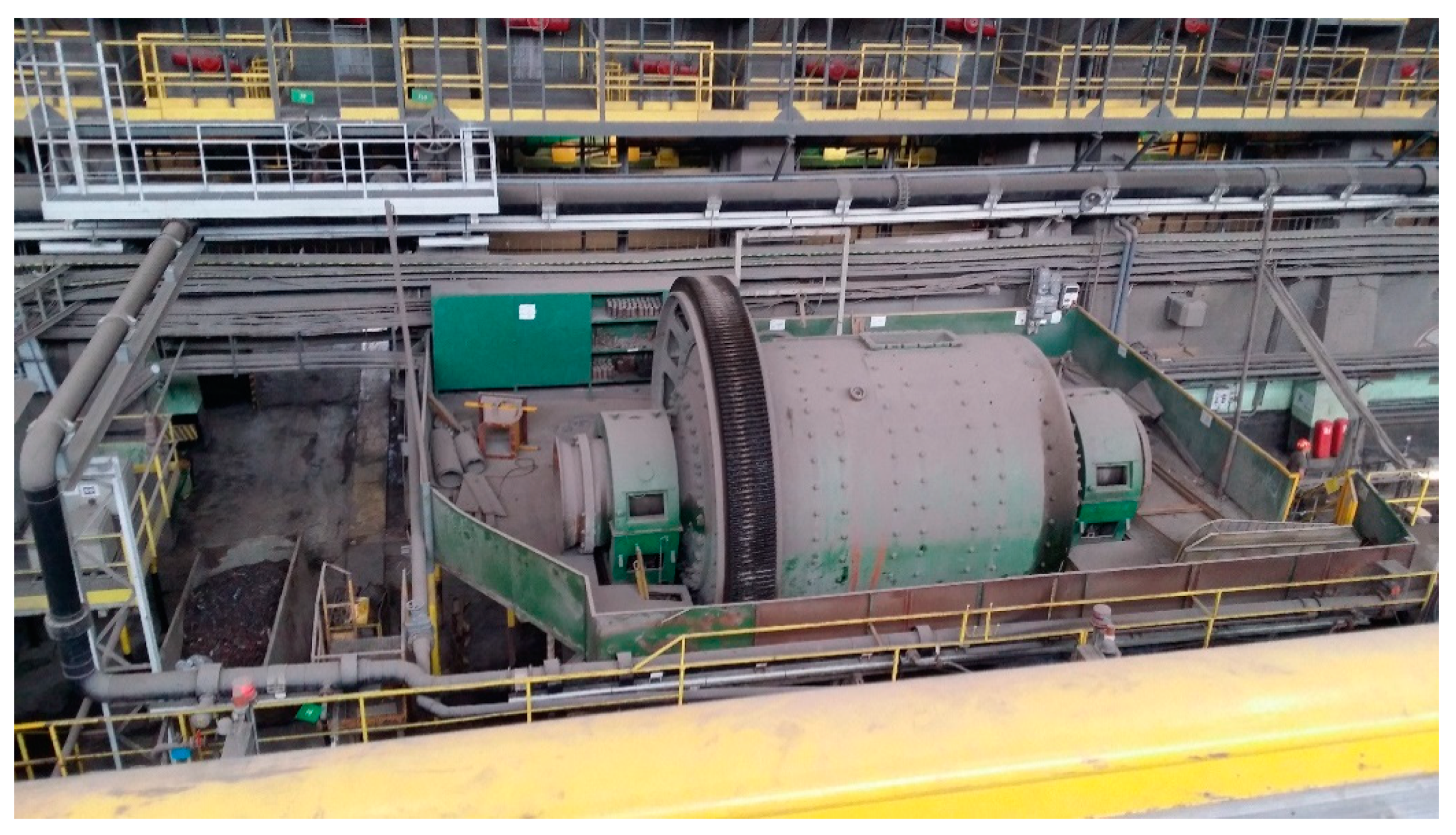
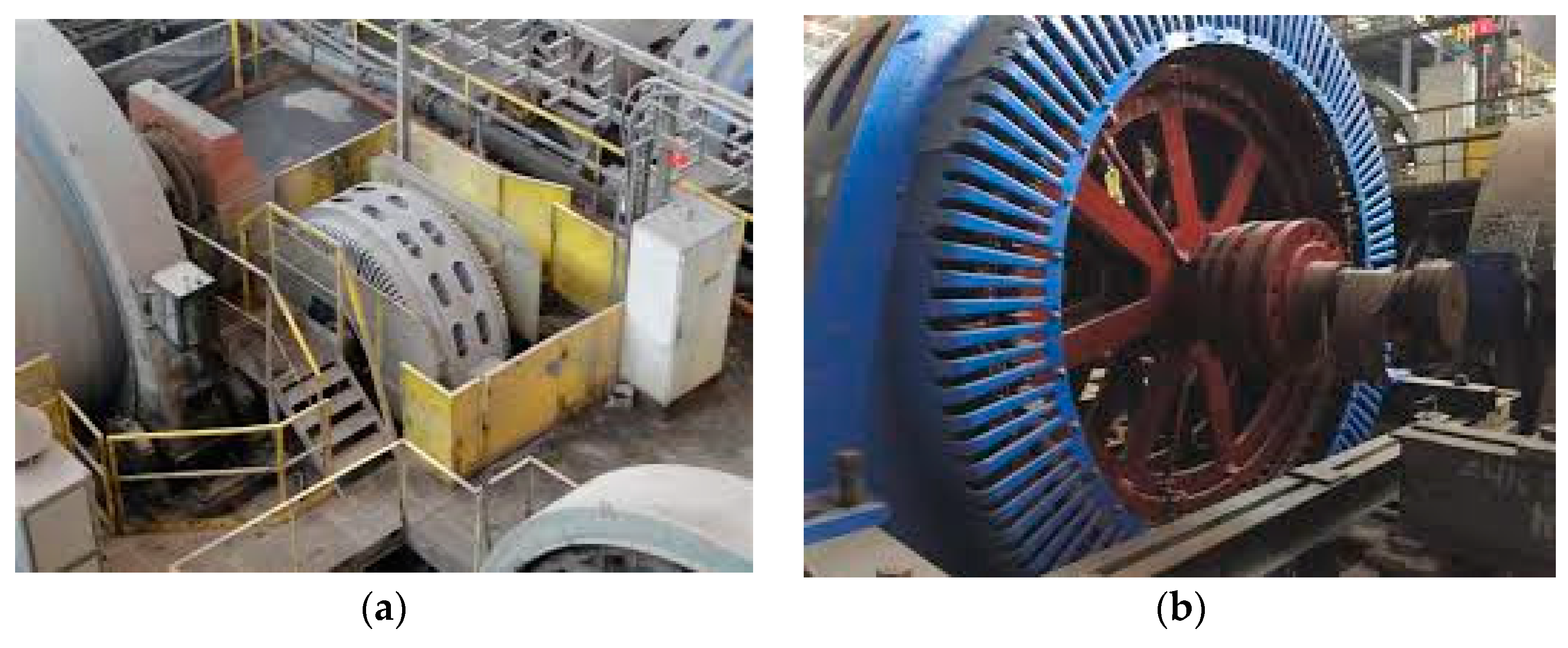
3.1. Traditional Drive System with SAS Motors
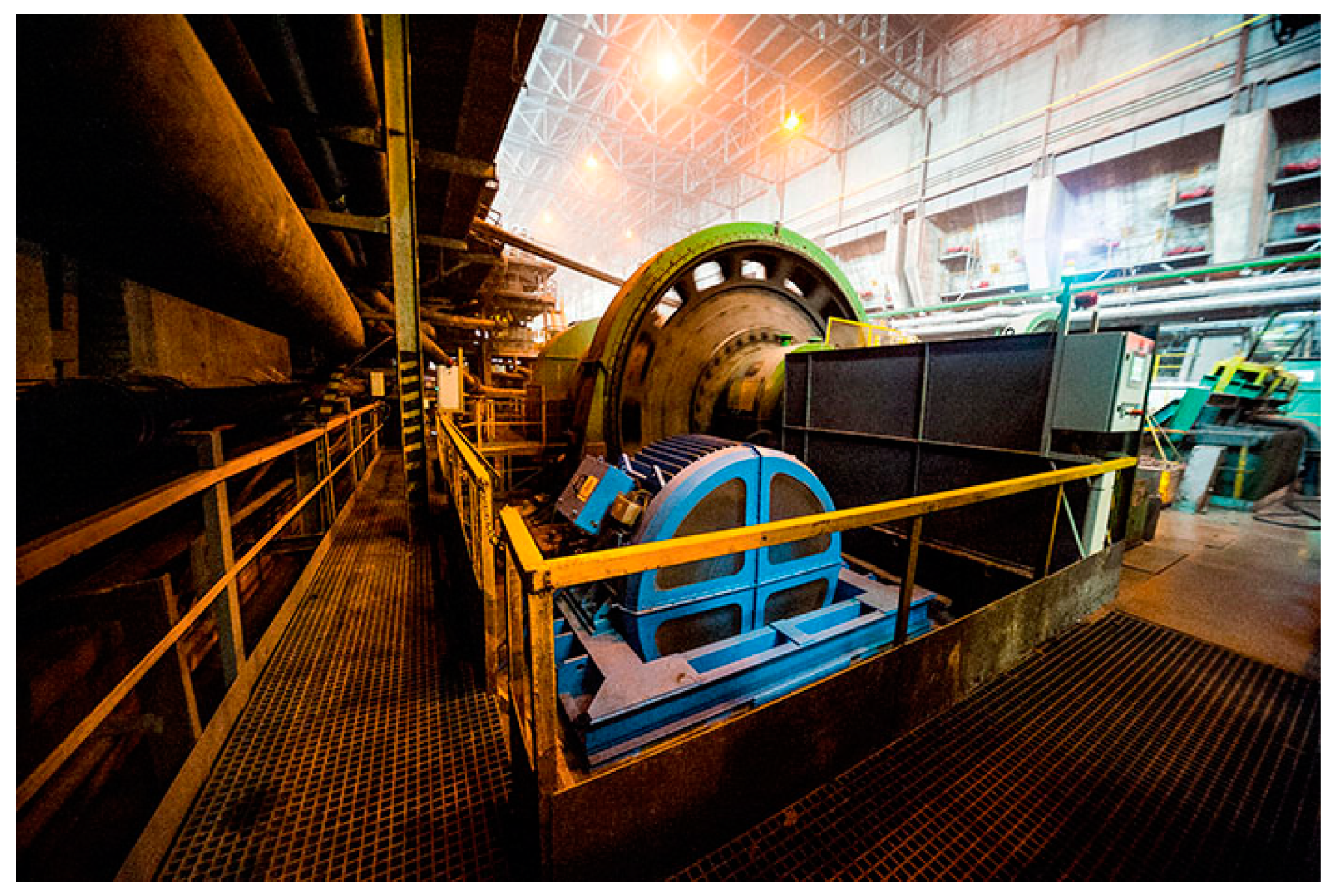
3.2. The Drive System with a Low-Speed Motor Type LSPMSM SMH-1732T
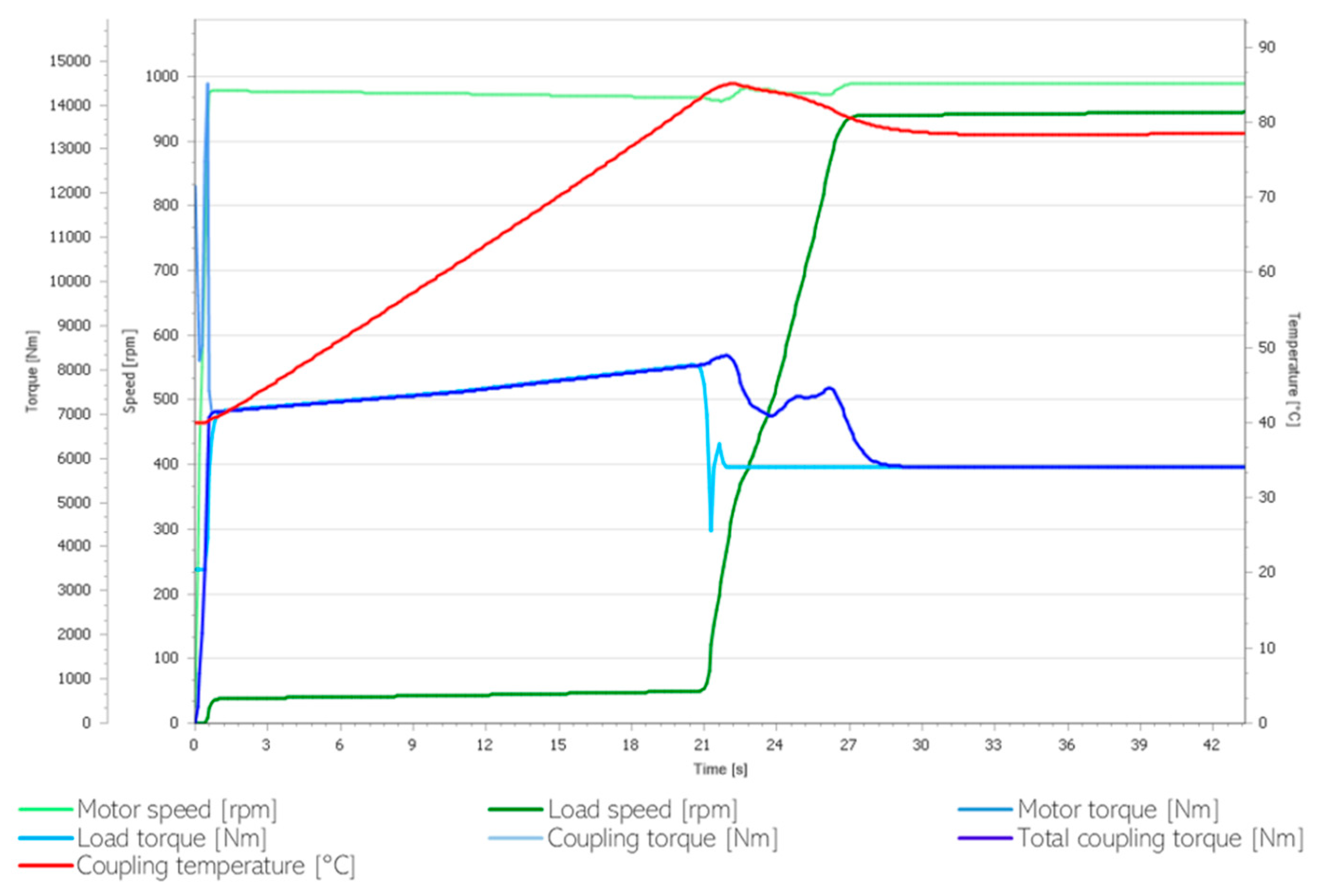
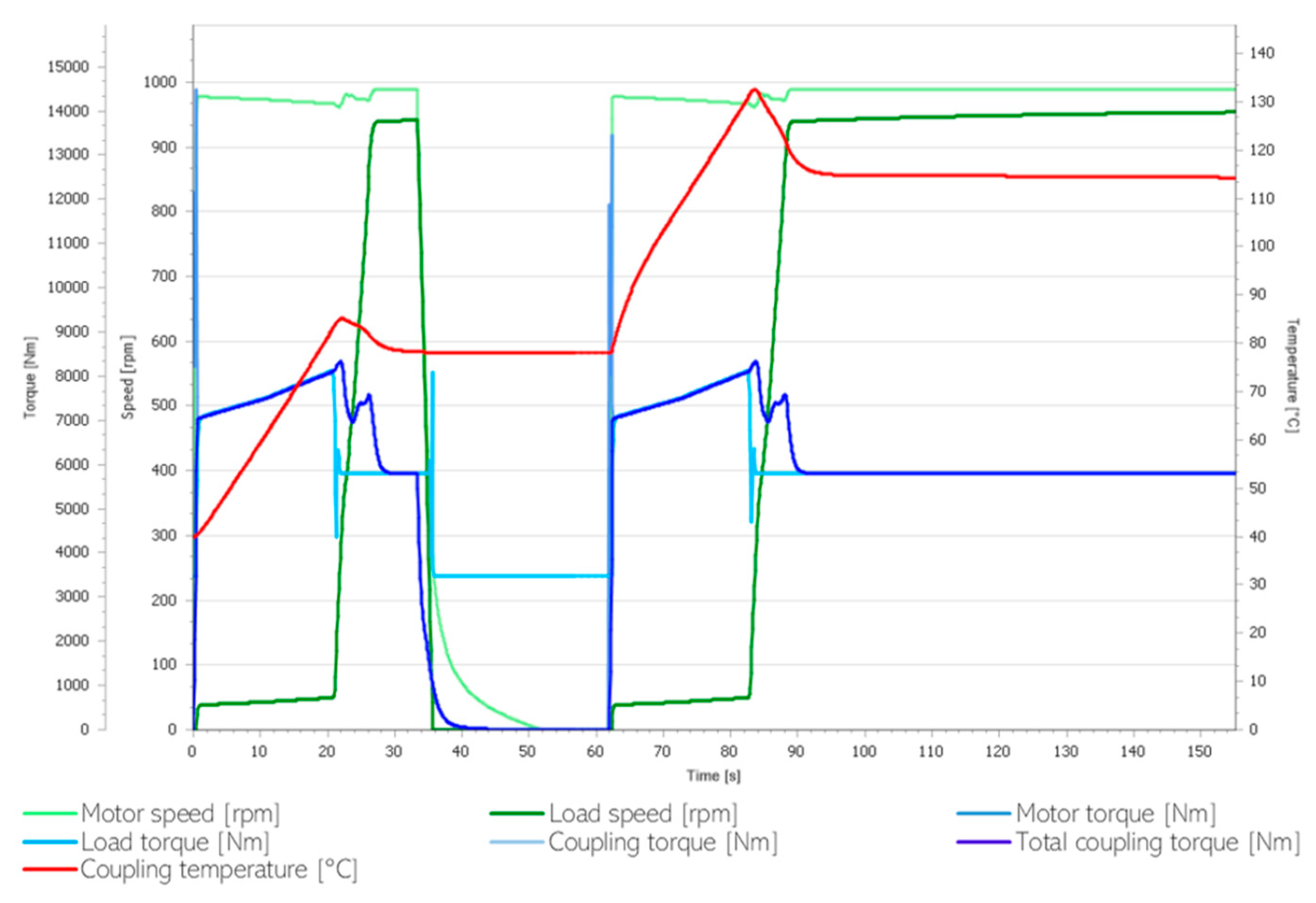
3.3. Drive System with Asynchronous High-Efficiency Motor, with Gearbox, and with Fluid Coupling
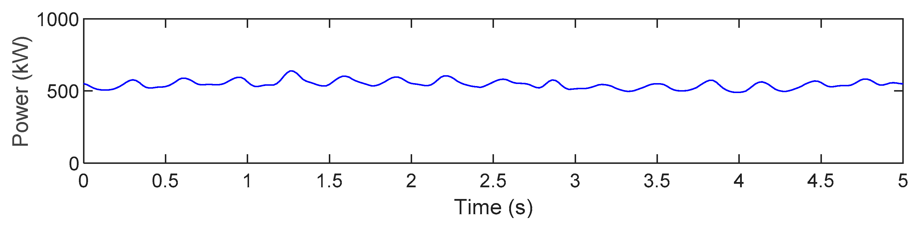
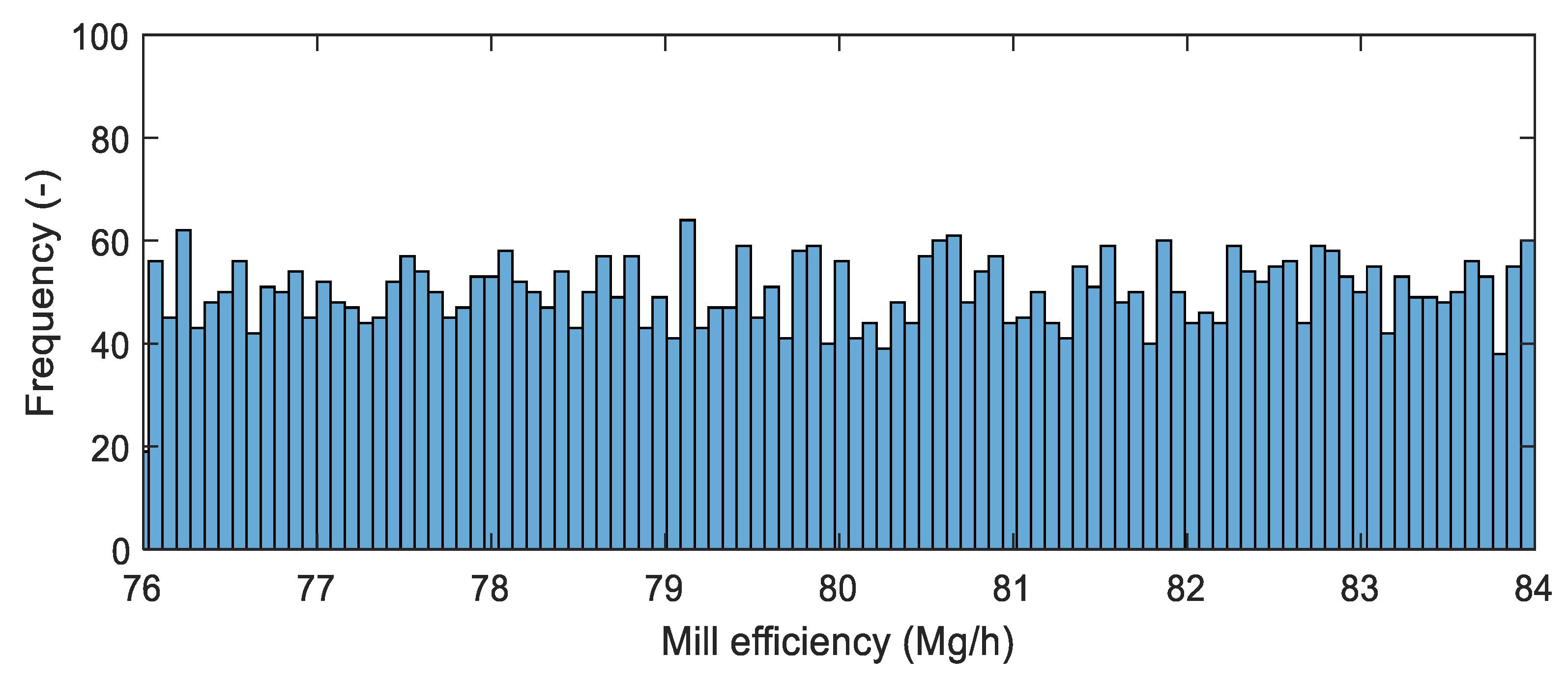
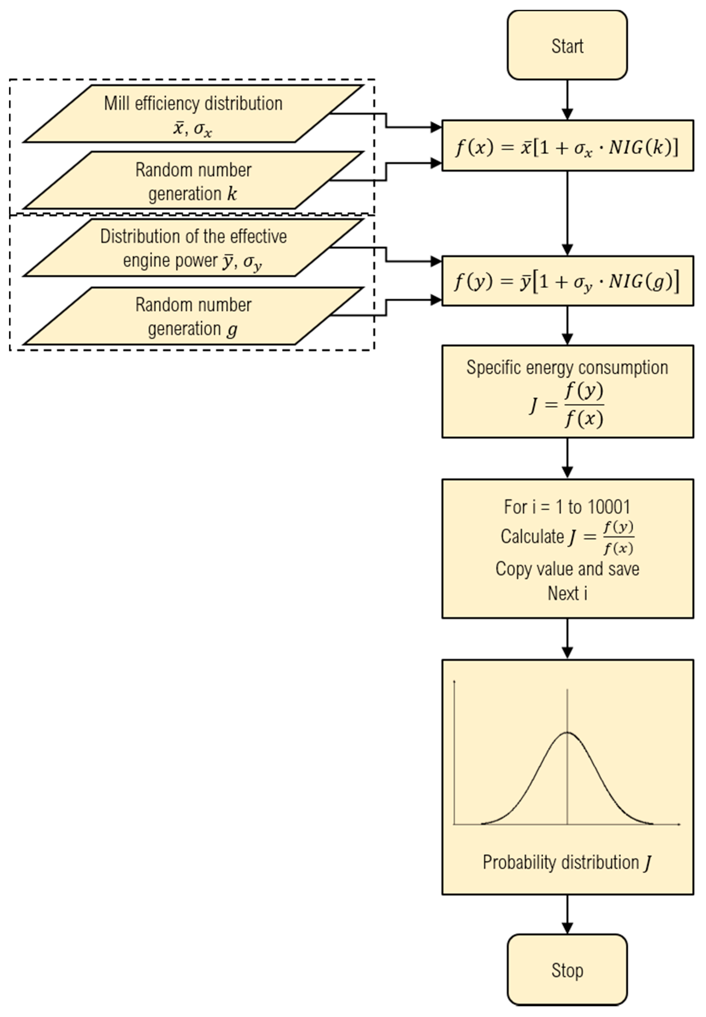
4. Energy Efficiency Evaluation of the Analyzed Drive Systems
5. Conclusions
Author Contributions
Funding
Institutional Review Board Statement
Data Availability Statement
Conflicts of Interest
References
- Malinauskaite, J.; Jouhara, H.; Ahmad, L.; Milani, M.; Montorsi, L.; Venturelli, M. Energy efficiency in industry: EU and national policies in Italy and the UK. Energy 2019, 172, 255–269. [Google Scholar] [CrossRef]
- Giridhar Kini, P.; Bansal, C.R. Energy Efficiency in Industrial Utilities. Energy Manag. Syst. 2011. [Google Scholar] [CrossRef][Green Version]
- Kumar, A. Technomine, Mining Technology. Available online: http://technology.infomine.com/reviews/comminution/welcome.asp?view=full (accessed on 4 November 2020).
- Jankovic, A.; Valery, W.; La Rosa, D. Fine Grinding in the Australian Mining Industry; Universiti Sains Malaysia: Nibong Tebal, Malaysia, 2008. [Google Scholar]
- Jeswiet, J.; Szekeres, A. Energy Consumption in Mining Comminution. Procedia CIRP 2016, 48, 140–145. [Google Scholar] [CrossRef]
- DOE. Comminution and Energy Consumption: Report of the Committee on Comminution and Energy Consumption; U.S. Department of Energy: Washington, DC, USA, 1981.
- De Bakker, J. Energy Use of Fine Grinding in Mineral Processing. Metall. Mater. Trans. E 2014, 1, 8–19. [Google Scholar] [CrossRef]
- Wojciechowski, B. Nie tylko wydobywamy. Energetyka Cieplna i Zawodowa 2015, 2, 20–23. [Google Scholar]
- Rumpf, H. Problems of scientific development in particle technology, looked upon from a practical point of view. Powder Technol. 1977, 18, 3–17. [Google Scholar] [CrossRef]
- Sidor, J. Directions in development of mills for raw materials and mineral binders grinding. Mater. Ceram. 2016, 68, 61–69. [Google Scholar]
- Tamblyn, R.J. Analysis of Energy Requirements in Stirred Media Mills. Ph.D. Thesis, University of Birmingham, Birmingham, UK, 2009. [Google Scholar]
- Krawczykowski, D.; Gawenda, T.; Foszcz, D. Comparison of real and theoretically estimated energy consumption for ball grinder. Min. Geoengin. 2006, 30, 79–90. [Google Scholar]
- Wang, M.H.; Yang, R.Y.; Yu, A.B. DEM investigation of energy distribution and particle breakage in tumbling ball mills. Powder Technol. 2012, 223, 83–91. [Google Scholar] [CrossRef]
- Mayank, K.; Malahe, M.; Govender, I.; Mangadoddy, N. Coupled DEM-CFD Model to Predict the Tumbling Mill Dynamics. Procedia IUTAM 2015, 15, 139–149. [Google Scholar] [CrossRef]
- Marchal, G. Industrial experience with clinker grinding in the HOROMILL. In Proceedings of the IEEE Cement Industry Technical Conference (Paper), Hershey, PA, USA, 20–24 April 1997; pp. 195–211. [Google Scholar]
- Tesema, G.; Worrell, E. Energy efficiency improvement potentials for the cement industry in Ethiopia. Energy 2015, 93, 2042–2052. [Google Scholar] [CrossRef]
- Telichenko, V.I.; Sharapov, R.R.; Lozovaya, S.Y.; Skel, V.I. Analysis of the efficiency of the grinding process in closed circuit ball mills. In Proceedings of the MATEC Web of Conferences, EDP Sciences, Amsterdam, The Netherlands, 23–25 March 2016; Volume 86, p. 4040. [Google Scholar]
- Rowland, C.A.; Erickson, M.T. Large Ball Mill Scale-Up Factors to Be Studied Relative to Grinding Efficiency. Miner. Metall. Process. 1984, 1, 165–172. [Google Scholar] [CrossRef]
- Fuerstenau, D.W.; Lutch, J.J.; De, A. The effect of ball size on the energy efficiency of hybrid high-pressure roll mill/ball mill grinding. Powder Technol. 1999, 105, 199–204. [Google Scholar] [CrossRef]
- Zheng, J.; Harris, C.C.; Somasundaran, P. A study on grinding and energy input in stirred media mills. Powder Technol. 1996, 86, 171–178. [Google Scholar] [CrossRef]
- Costea, C.; Silaghi, H.; Silaghi, M.; Silaghi, P. Mill speed control using programmable logic controllers. In Proceedings of the International Conference on Mathematical Methods and Computational Techniques in Electrical Engineering, Timișoara, Romania, 21–23 October 2010; World Scientific and Engineering Academy and Society (WSEAS): Stevens Point, WI, USA, 2010; pp. 26–30, ISBN 978-960-6766-60-2. [Google Scholar]
- El-Shall, H.; Somasundaran, P. Physico-chemical aspects of grinding: A review of use of additives. Powder Technol. 1984, 38, 275–293. [Google Scholar] [CrossRef]
- Pacholski, E.; Iskierski, L. The analisis of influence of start-up mode of drive motors to electric network parameters. Electr. Mach. Trans. J. 2013, 2, 99. [Google Scholar]
- Bianchi, N.; Bolognani, S.; Frare, P. Design criteria for high-efficiency SPM synchronous motors. IEEE Trans. Energy Convers. 2006, 21, 396–404. [Google Scholar] [CrossRef]
- Lu, X.; Iyer, K.L.V.; Mukherjee, K.; Kar, N.C. Development of a novel magnetic circuit model for design of premium efficiency three-phase line start permanent magnet machines with improved starting performance. IEEE Trans. Magn. 2013, 49, 3965–3968. [Google Scholar] [CrossRef]
- Stoia, D.; Chirilǎ, O.; Cernat, M.; Hameyer, K.; Ban, D. The behaviour of the LSPMSM in asynchronous operation. In Proceedings of the EPE-PEMC 2010—14th International Power Electronics and Motion Control Conference, Ohrid, North Macedonia, 6–8 September 2010; pp. T4–T45. [Google Scholar]
- Mayer, C.B.; Johnson, R.M.; Gray, D.J. Solution of a Serious Repetitive Vibration Problem on a 4500-hp Single-Pinion Synchronous Motor Ball Mill Drive. IEEE Trans. Ind. Appl. 1985, IA-21, 1039–1046. [Google Scholar] [CrossRef]
- Zawilak, T.; Zawilak, J. Energy-efficient motor in ball mill applcation. Drives Control 2017, 19, 68–72. [Google Scholar]
- Gao, X.; Wang, X.; Wei, Z. Design and control of high-capacity and lowspeed doubly fed start-up permanent magnet synchronous motor. IET Electr. Power Appl. 2018, 12, 1350–1356. [Google Scholar] [CrossRef]
- Mirošević, M.; Maljković, Z. Effect of sudden change load on isolated electrical grid. In Proceedings of the Electrical Systems for Aircraft, Railway and Ship Propulsion, ESARS, Aachen, Germany, 3–5 March 2015; pp. 1–4. [Google Scholar]
- McElveen, R.F.; Toney, M.K. Starting high-inertia loads. IEEE Trans. Ind. Appl. 2001, 37, 137–144. [Google Scholar] [CrossRef]
- Leng, S.; Ul Haque, A.R.N.M.R.; Perera, N.; Knight, A.; Salmon, J. Soft Start and Voltage Control of Induction Motors Using Floating Capacitor H-Bridge Converters. IEEE Trans. Ind. Appl. 2016, 52, 3115–3123. [Google Scholar] [CrossRef]
- Zenginobuz, G.; Çadirci, I.; Ermiş, M.; Barlak, C. Soft starting of large induction motors at constant current with minimized starting torque pulsations. IEEE Trans. Ind. Appl. 2001, 37, 1334–1347. [Google Scholar] [CrossRef]
- Pacholski, E.; Leśnik, M. Sas motors exploitation in kghm polska miedz s.a. division of concentrator. Experience, problems, priority activities. Electr. Mach. Trans. J. 2012, 1, 153–157. [Google Scholar]
- Zawilak, T. Synchronous motors excited by permanent magnets in high power drives. Przegląd Elektrotechniczny 2017, 1, 175–178. [Google Scholar] [CrossRef]
- Kisielewski, P.; Leśnik, M.; Pacholski, E.; Zawilak, J.; Zawilak, T. Design, construction and testing of prototypes series of large synchronous motors with permanent magnets. Electr. Mach. Trans. J. 2016, 3, 191–195. [Google Scholar]
- KGHM Polska Miedź S.A. Promotional Materials; KGHM Polska Miedź S.A.: Lubin, Poland, 2020. [Google Scholar]
- Start, L.; Magnet, P.; Motor, S.; Ball, I.N. Line start permanent magnet synchronous motor in ball mill application. Electr. Mach. Trans. J. 2016, 2016, 169–173. [Google Scholar]
- Ni, R.; Xu, D.; Blaabjerg, F.; Wang, G.; Li, B.; Lu, K. Synchronous switching of non-line-start permanent magnet synchronous machines between inverter and grid drives. In Proceedings of the 2016 IEEE Energy Conversion Congress and Exposition (ECCE), Milwaukee, WI, USA, 18–22 September 2016; Volume 31, pp. 3717–3727. [Google Scholar] [CrossRef]
- Brun, K.; Meyenberg, C.; Thorp, J. Hydrodynamic torque converters for oil & gas compression and pumping applications: Basc principles, performance characteristics and applications. In Proceedings of the Asia Turbomachinery & Pump Symposium, Singapore, 22–25 February 2016; Turbomachinery Laboratories, Texas A&M Engineering Experiment Station: College Station, TX, USA, 2016; p. 15. [Google Scholar]
- Heisler, H. Hydrokinetic fluid couplings and torque converters. In Advanced Vehicle Technology; Elsevier: Amsterdam, The Netherlands, 2002; pp. 98–116. ISBN 9780750651318. [Google Scholar]
- Huitenga, H.; Mitra, N.K. Improving startup behavior of fluid couplings through modification of runner geometry: Part I—Fluid flow analysis and proposed improvement. J. Fluids Eng. Trans. ASME 2000, 122, 689–693. [Google Scholar] [CrossRef]


| No. | Parameter | Variant 1 (SAS) | Variant 2 (SMH) | Variant 3 (New Drive) |
|---|---|---|---|---|
| 1 | Average | 601.77 | 429.75 | 600.04 |
| 2 | Standard error | 0.57 | 0.45 | 0.08 |
| 3 | Standard deviation | 29.68 | 7.74 | 1.43 |
| 4 | Variance | 880.93 | 59.84 | 2.04 |
| 5 | Kurtosis | 0.03 | −0.20 | −1.12 |
| 6 | Skewness | 0.50 | −0.22 | 0.09 |
| No. | Parameter | Variant 1 (SAS) | Variant 2 (SMH) | Variant 3 (New Drive) |
|---|---|---|---|---|
| 1 | Average | 601.709 | 438.141 | 598.457 |
| 2 | Standard deviation | 10.823 | 3.038 | 1.993 |
| 3 | Variance | 117.143 | 9.231 | 3.974 |
| 4 | Kurtosis | −0.012 | 0.042 | 0.041 |
| 5 | Skewness | 0.012 | −0.011 | 0.034 |
| 6 | MAE | 8.642 | 2.408 | 1.585 |
| 7 | RMSE | 10.823 | 3.038 | 1.993 |
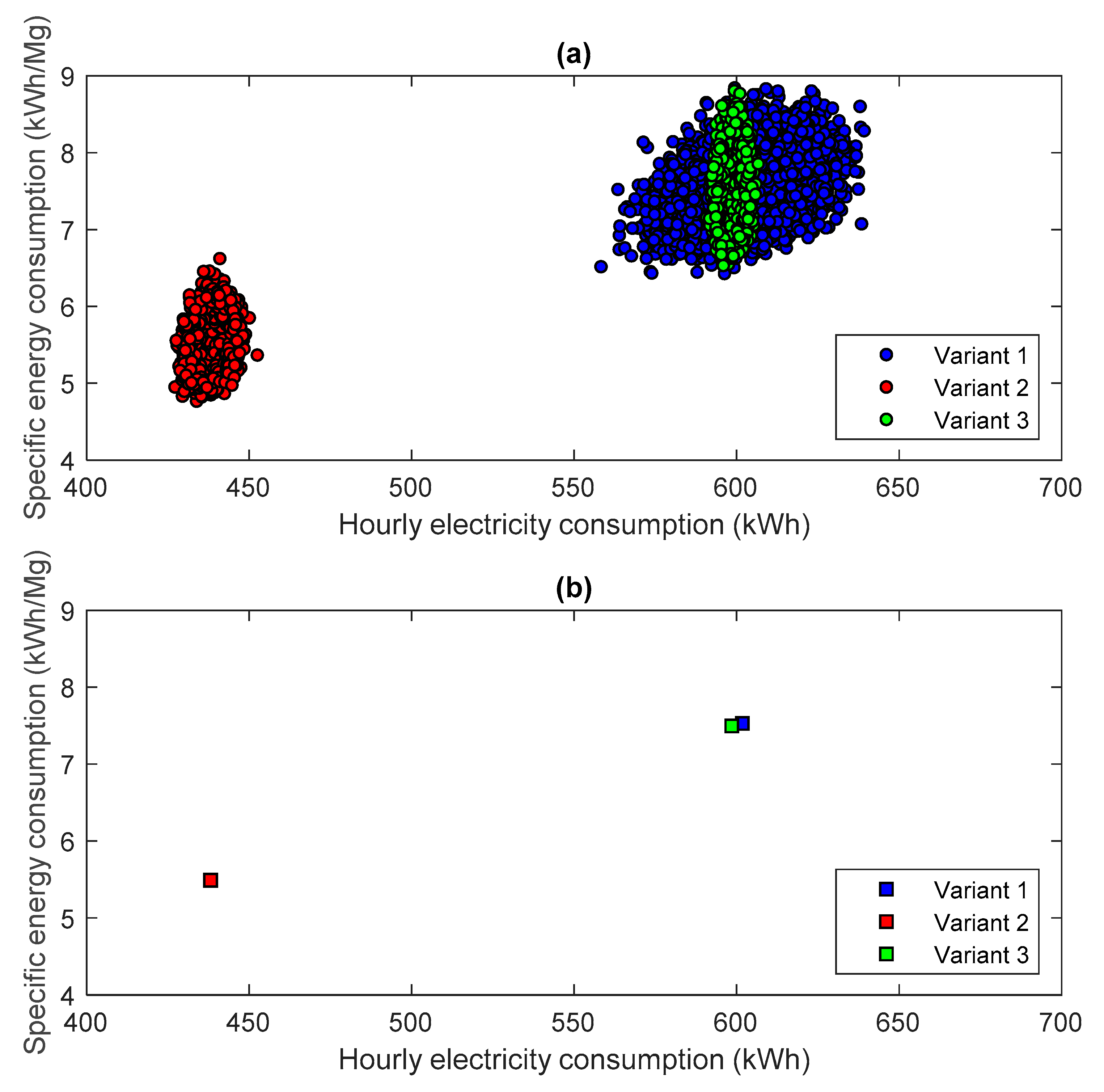
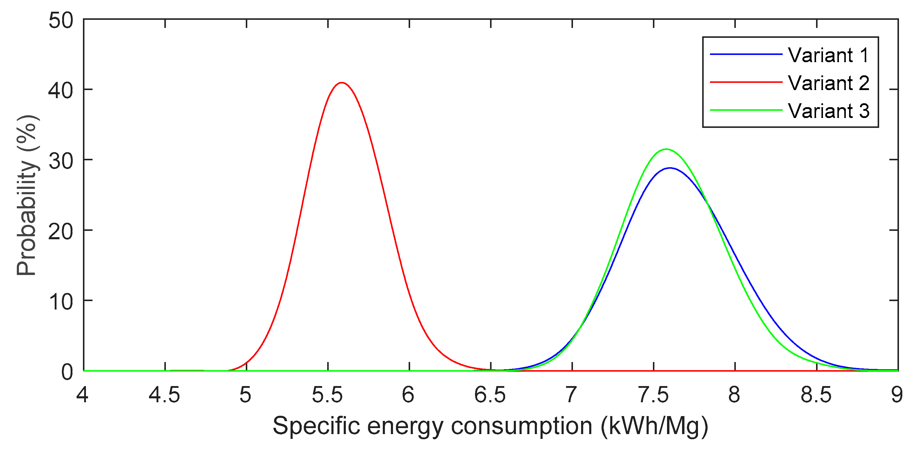
| No. | Parameter | Variant 1 (SAS) | Variant 2 (SMH) | Variant 3 (New Drive) |
|---|---|---|---|---|
| 1 | Average | 7.530 | 5.489 | 7.496 |
| 2 | Standard deviation | 0.340 | 0.230 | 0.310 |
| 3 | Variance | 0.116 | 0.053 | 0.096 |
| 4 | Kurtosis | 0.030 | 0.129 | 0.101 |
| 5 | Skewness | 0.224 | 0.237 | 0.256 |
| 6 | MAE | 0.272 | 0.183 | 0.247 |
| 7 | RMSE | 0.340 | 0.230 | 0.310 |
Publisher’s Note: MDPI stays neutral with regard to jurisdictional claims in published maps and institutional affiliations. |
© 2021 by the authors. Licensee MDPI, Basel, Switzerland. This article is an open access article distributed under the terms and conditions of the Creative Commons Attribution (CC BY) license (http://creativecommons.org/licenses/by/4.0/).
Share and Cite
Bortnowski, P.; Gładysiewicz, L.; Król, R.; Ozdoba, M. Energy Efficiency Analysis of Copper Ore Ball Mill Drive Systems. Energies 2021, 14, 1786. https://doi.org/10.3390/en14061786
Bortnowski P, Gładysiewicz L, Król R, Ozdoba M. Energy Efficiency Analysis of Copper Ore Ball Mill Drive Systems. Energies. 2021; 14(6):1786. https://doi.org/10.3390/en14061786
Chicago/Turabian StyleBortnowski, Piotr, Lech Gładysiewicz, Robert Król, and Maksymilian Ozdoba. 2021. "Energy Efficiency Analysis of Copper Ore Ball Mill Drive Systems" Energies 14, no. 6: 1786. https://doi.org/10.3390/en14061786
APA StyleBortnowski, P., Gładysiewicz, L., Król, R., & Ozdoba, M. (2021). Energy Efficiency Analysis of Copper Ore Ball Mill Drive Systems. Energies, 14(6), 1786. https://doi.org/10.3390/en14061786