Article

Tribo-Electrostatic Separation Analysis of a Beneficial Solution in the Recycling of Mixed Poly(Ethylene Terephthalate) and High-Density Polyethylene

by
Wieslaw Lyskawinski
1,
Mariusz Baranski
1,*,
Cezary Jedryczka
1,
Jacek Mikolajewicz
1,
Roman Regulski
2,
Dariusz Sedziak
2,
Krzysztof Netter
2,
Dominik Rybarczyk
2,
Dorota Czarnecka-Komorowska
3 and
Mateusz Barczewski
3
1
Faculty of Control, Robotics and Electrical Engineering, Institute of Electrical Engineering and Electronics, Poznan University of Technology, 60-965 Poznan, Poland
2
Faculty of Mechanical Engineering, Institute of Mechanical Technology, Poznan University of Technology, 60-965 Poznan, Poland
3
Faculty of Mechanical Engineering, Institute of Materials Technology, Poznan University of Technology, 60-965 Poznan, Poland
*
Author to whom correspondence should be addressed.
Energies 2021, 14(6), 1755; https://doi.org/10.3390/en14061755
Submission received: 27 February 2021 / Revised: 15 March 2021 / Accepted: 19 March 2021 / Published: 22 March 2021
(This article belongs to the Section B: Energy and Environment)

Abstract

:
The aim of this study was to investigate and analyze the impact of selected parameters during the tribocharging process of shredded poly(ethylene terephthalate) (PET) and high-density polyethylene (PE-HD) plastics on accumulated electric charge and electrostatic separation effectiveness. The accumulation of electric charge on surfaces of polymer particles as a result of their circular motion forced by the airflow cyclone container was investigated. The impact of the container material, time of tribocharging and the airflow intensity were experimentally examined. A container in which the particles of the considered polymers are electrified with opposite charges was selected. A high ability to accumulate surface charge on small particles of both polymers was demonstrated. The electrified mixed PET/PE-HD was subjected to a separation process. An electrostatic separator designed and constructed by the authors was used for to the separation. In turn, to assess the effectiveness of this separation, a dedicated vision system was used. Based on the result of the carried out tests, it has been assumed that the proposed approach’s effectiveness has been demonstrated by means of empirical validation.

1. Introduction

The increased mass consumerism observed in recent years has led to many serious problems related to the environmental pollution of our planet [1,2,3,4]. One of the most crucial problems is the drastic increase in the generation of polymer waste. Inappropriate waste management, including low recovery rates, can have serious environmental effects. Landfills occupy large areas and can cause air, water and soil pollution. Waste incineration, on the other hand, can result in the emission of pollutants into the atmosphere. For these reasons, efforts are undertaken to reduce the impact of waste on the environment and human health by effectively recycling it for reuse. Post-consumer waste processing is a difficult task for organizational and technical reasons and necessitates a need to develop new solutions in mechanical recycling technologies [5].
Today, plastics are widely used in various industries, which, compared to metals, are characterized by low density and resistance to corrosion. These materials have excellent insulating properties, both electrical and thermal. The easy formation of complex shapes by the use of fillers, dyes or foaming agents allows the combination of materials with different properties. For these reasons plastics are widely used in all areas of the economy, to some extent replacing metal, glass, wood or ceramics [6,7,8]. Unfortunately, the resulting wastes are characterized by a different chemical composition and, consequently, different properties. Therefore, wastes require the use of different recycling technologies. In order to obtain a pure material from the waste material suitable for further use in the recycling process, it is necessary to perform a number of operations such as: accumulation, cleaning, sorting, shredding, separation, washing, drying [9]. Undoubtedly, the most troublesome and significant stage is separation. Separation is a process of separating a heterogeneous system, e.g., mixed polymer fractions on the basis of differences in certain physical properties, e.g., specific density, hardness, particle size, wettability [10]. In recycling polymeric waste, electrostatic separation, i.e., separation using an electric field is used [11,12,13,14,15]. It is an environmentally friendly technique that uses electric field forces exerted on electrified plastic particles.

1.1. Electrostatic Separation Method

Electrostatic separation is a well-known and increasingly used method for dry sorting of mixed polymers, which has become a focus of scientific and industrial communities [16,17,18]. It consists of three stages. In the first stage, the polymer waste is shredded into fractions with dimensions not exceeding a few millimeters. The second stage consists of electrifying particles of plastics by the corona discharge or in cylindrical mixers, shaking conveyors or fluidized beds using the contact-friction method, resulting in the creation of electric charges on the surface of the mixture components. The formation of electric charges is a consequence of the contact between surfaces of two solids and occurs due to their mutual friction by sliding, rolling, impact, vibration or deformation. The process is called tribo-electric charging or simply tribocharging [19,20,21,22]. As a result of the electrification of particles of mixed plastics in the contact-friction process, positive and negative electric charges accumulate on the surface of the plastics. This method takes advantage of the phenomenon of different electrical permeability of separated plastics, which is an indirect measure of the ability of a given plastic to accumulate electrostatic charge on its surface as a result of friction with another plastic. This method of electrification creates the possibility of application of electrostatic separation for a wide range of materials, including poly(ethylene terephthalate) (PET), polychloride vinyl (PVC) and high-density polyethylene (PE-HD) [23,24,25,26]. In the third stage, the mixture is separated in a strong electrostatic field depending on the size and polarity of the electrostatic charge accumulated on the surface of the separated polymer material [27].

1.2. Triboelectrification Process

The process of triboelectrification takes advantage of differences in the triboelectric properties of polymers, i.e., the ability to accumulate electrostatic charge on their surface due to rubbing against another material. Several particle electrification methods can be distinguished: mechanical triboelectrification, fluidization triboelectrification, electrification in a stream of electrons and ions created by the corona discharge, electrification by induction, or electrification occurring in an electrostatic field [28]. The most common method is mechanical triboelectrification, in which two different polymers obtain negative and positive charges as a result of mutual rubbing. Such electrified material undergoes a separation process. Mixtures are separated in an electrostatic field between two electrodes, e.g., a high voltage electrode and a grounded electrode. Separating devices called separators are used for this purpose.

1.3. Types of Electrostatic Separators

Two groups of separators are most commonly used: free-fall separators (see Figure 1) or separators with rotating cylindrical electrodes (see Figure 2) [27].
The free-fall electrostatic separator is characterized by the fact that electrified material particles fall freely in the electrostatic field of the separation system. Most often in the construction of the free-fall separator there are two positive and negative electrodes, which generate a strong electrostatic field. [21,28,29].
The charged particles are then introduced into an electric field generated between the plate electrodes by various means of transport (gravity, pneumatics, vibration). In electric field, the charged particles move towards the oppositely charged electrodes and are collected in the corresponding boxes. The fraction containing a mixture of particles of both polymers may or may not be collected, depending on the configuration of the separation device.
Spinning electrode separators are high voltage drum (roller) or belt separators. They are the most common separator designs reported in the literature [30,31,32]. Particle charging mechanisms take place primarily using triboelectricity or corona charging.
High voltage electrostatic drum (roller) separators are used in many industries. Many variations and geometries are used in high voltage roller systems, but they generally operate on similar principles.
Particles of different conductivities electrify in the relief field and fall onto the drum, which is electrically grounded. The well-conducting particles give up their charge, are pulled away from the drum surface, and are placed in collection boxes in the zone furthest from the drum. In contrast, the poorly conductive particles retain their charge and are held on the drum surface. Eventually the electrical charge on the poorly conductive particles dissipates or the particles are brushed off the drum after the drum is rotated. These particles are deposited in the collection boxes closest to the drum.
Forces acting on particles placed in an electric field [33] can be described by the following equation:
F e = 2 π R 3 ε 1 ε 2 ε 1 ε 2 2 ε 1 E 2 + QE
where: Fe is the electric force (N), R is the radius of the particle, ε1 is the relative permittivity of the particle, ε2 is the relative permittivity of the medium, E is the electric field intensity (Vm−1), Q is the electric charge of the particle (C).
The first component of Equation (1) describes the diaphoresis force appearing only in inhomogeneous fields, while the second component of this equation describes the electrophoresis force acting on the charged particle. The diaphoresis force occurs in non-uniform fields. Using it for separation purposes is problematic because it requires a large electric field gradient, which creates many technical difficulties. The second component of Equation (1) determines the electrophoresis force, which is the force of an electric field acting on a previously charged particle [33].
The main subject of the study was the analysis of the influence of selected parameters of the mechanical tribocharging process on the polarization and value of electric charge accumulated on the particle surface. The focus of the conducted research was paid on searching conditions allowing to obtain the highest possible electrostatic charge. The influence of blower air flow rate, size and mass of the particles subjected to the tribocharging process and the material of the containers were studied. Effectiveness of the electrostatic separation of mixture of waste materials, i.e., PET and PE-HD was tested using a proprietary computerized vision system described in [27]. A detailed analysis of the obtained results of tribocharging of the tested materials were presented and discussed.

2. Materials and Methods

2.1. Materials and Samples Preparation

The success of material recycling of plastic waste is determined by an effective process of obtaining as many thermoplastics as possible, preferably without changing their structure and properties, so that they can be reused in the production of the same or new products [17,26]. The most crucial aspect in recycling materials is their proper preparation, i.e., shredding, sorting, and identifying specific types to obtain the highest possible purity of the separated materials. The study investigated mixed post-consumer waste of poly(ethylene terephthalate) (PET) and high-density polyethylene (PE-HD), two different polymers which, from the point of view of the physico-chemistry of polymers, are immiscible under processing conditions. A Shini SG 1411 CE X X (Shini Plastics Technologies Inc. Taiwan) slow-speed mill was used to grind the investigated plastics (Figure 3). The granulator is designed for grinding polymer waste materials. It is characterized by easy, quiet operation, high durability, efficiency, and low dustiness of the final grounded product. Small crushing blades and milling modules (Figure 3a) made of high-quality steel with high hardness ensure obtaining particles of small size. The granulator is driven by a 0.37 kW geared motor.
As a result of comminution, polymer fractions with different particle sizes were obtained and subjected to sieve analysis using sieves with nominal dimensions (d) is 4 mm, 2.8 mm and 1.8 mm, as vibratory sieve shaker ANALYSETTE 3 (FRITSCH GmbH, Idar-Oberstein, Germany)(see Figure 4)., four fractions with different particle sizes (smaller than 1.8 mm, between 1.8 and 2.8 mm, between 2.8 and 4 mm and larger than 4 mm) were obtained as a result of the separation (Figure 5). The percentages of the particular fractions of the investigated PET and PE-HD polymers are summarized in Table 1.

2.2. Electrification of Polymer Fractions

Next, studies related to the electrification ability of the obtained fractions of both materials (PET and PE-HD) were carried out. A humidity of 29% and a temperature of 22 °C of the polymer particles were kept constant during the tests. These parameters corresponded to the ambient humidity and temperature. Each fraction of both polymers was tribocharged by circulation in one of several containers (Figure 6) made of different materials.
The dimensions of the containers were comparable (see Figure 7a). The circulatory (swirling) air movement inside the containers (see Figure 7b) was obtained using an OK-1680 type blower with a power of 1400 W that adjusted airflow in the range of 1.27–2.19 m3/min cubic meters per minute, (cpm) generating a suction of 21 kPa. In the containers shown in Figure 6 the air is introduced tangentially to their center and circulated in a cyclone manner. The blower drew the air from the containers through an outlet opening in the suction head (Figure 6e), which caused the particles placed in the container to whirl due to the cyclone effect. A cylindrical filter (Figure 6b) with a diameter of 70 mm and a length of 100 mm was placed at the outlet head. As a result, the usable volume of the containers used in the tribocharging process is about 0.7 L. The filter attached to the outlet head protects the plastic particles from being sucked out by the blower. In the tribocharging process of both polymers, containers made of poly(ethylene terephthalate) glycol-modified (PET-G), acrylic-styrene-acrylonitrile copolymer (ASA) polypropylene copolymer (PP), acrylonitrile-butadiene-styrene (ABS), and polylactic acid (PLA) were used.
After tribocharging, the electrified particles of both plastics were poured into a Faraday pail connected to the Charge Measuring Unit JCI 178X (Chilworth Technology Ltd. PHI House, Southampton Science Park, UK) and the charge accumulated in these particles was measured (see Figure 8). A container made of such material was sought in order to make PET and PE-HD particles electrified with electric charges of opposite polarity and to obtain the highest possible charge density (Q/m (nC/g)).
In the last stage of the study, separation tests were carried out for both materials mixed in equal amounts. Such a mixture of PET/PE-HD particles was tribocharged in several containers and separated using a prototype electrostatic separator (see Figure 9a) designed and built by the authors and described in detail in previous work [27]. The quality of the separation was evaluated using a vision system to assess the effectiveness of the separation. The advantages of the applied vision system (Figure. 9b) developed by the authors are discussed in detail in [27].

3. Results and Discussion

Preliminary studies have shown that PET particles electrify negatively in a polypropylene (PP) container and PE-HD electrify positively in a poly(ethylene terephthalate) (PET-G) container. Figure 10 and Figure 11 show the result of the electrification of PET and PE-HD particles of the two different fractions, that appeared in the most significant number (Table 1). Tribocharging was carried out at a constant airflow of about 1.6 cpm and varying tribocharging time. Based on the results, it can be concluded that electrified PET particles with negative charge appear much more often than PE-HD particles with positive charge. One can also observe a significantly greater increase in charge during short tribocharging than during long tribocharging. A smaller number of polymer particles subjected to tribocharging electrify more strongly because they rub against both the walls and the bottom of the containers, thus having a larger friction area.
In further experiments, the impact of different airflows while maintaining a constant tribocharging time of t = 30 s was examined. Selected results of the charging of particles in both materials for four fractions are summarized in Figure 12. Based on the analysis of the obtained results it can be concluded that the increase in the airflow during a tribocharging process causes greater electrification of particles of both materials. Out of the fractions studied, particles with small dimensions (fraction 1.8–2.8 mm and <1.8 mm) are the most electrified ones. On the other hand, particles with larger dimensions (fraction above 4 mm) are quite difficult to electrify in both materials. Both increasing the time and increasing the airflow for tribocharging results in very uneven electrification of the particles of both materials. Most of the particles are relatively weakly electrified 1–2 nC/g, however with a high airflow and long tribocharging time, a small number of particles become strongly electrified even above 50 nC/g. It was found that with a short time and lower airflow from the blower, the electrification of PET and PE-HD particles is quite uniform.
Studies of the electrification of the two materials in containers made of selected materials were also performed. It was tested in which of the containers both polymers would electrify with opposite charges—Figure 13. In addition to poly(ethylene terephthalate) glycol-modified (PET-G and polypropylene copolymer (PP) containers, containers made of acrylonitrile-butadiene-styrene terpolymer (ABS), acrylonitrile-styrene-acrylate terpolymer (ASA) and polylactide (PLA) were used. PET particles were not able to electrify in the PET-G container. Hence, the tests were conducted in the other four containers. The highest electrification of these particles was obtained using a container made of ASA and a PLA. Due to the similar level of electrification of PE-HD particles in these two containers, the results obtained for the ABS, ASA, PET-G and PP containers are summarized in Figure 13b. From the results shown in Figure 13, it can be seen that PET particles obtain a negative charge and PE-HD particles obtain a positive charge only in a PP container.
In further investigations, several separation tests were performed on a physical mixture of the two polymers with a particle size of 1.8–2.8 mm, with a weight share of 50% each. Such a particle size of the polymers can be electrified very well. First, the separation ability of such a 100 g mixture (50 g PET + 50 g PE-HD) was tested without a tribocharging process. In 17 boxes of material collectors, the separated particles accumulated mainly in one place with a small number of PET particles deflected towards the positive electrode of the separator (Figure 14a). Due to similar electrification effects of both polymers in ASA, PLA, PET-G, and ABS tribocharging containers, further separation tests of the mixture for both polymers were performed in PET-G, ASA and PP tribocharging containers. The tribocharging time was 60 s and the airflow was 2.19 cpm. The results of these trials are summarized in Figure 14b–c, while the evaluation of the separation efficiency of the particles for both plastics using the vision system developed by the authors is shown in Figure 15a–c. During the separation of both polymers on the separator (Figure 9a), constant settings of the corona electrode voltage of 27.4 kV, the distance between the electrodes d = 90 mm, and the feeder and the drum speed were assumed experimentally.
The degree of separation of the tested material was determined based on a dedicated vision system. The image was filtered using the HSV color space model (Figure 15). The HSV model parameters were selected experimentally and separately for each material. Next, the image was divided into segments (ROI—Region of Interest). For each segment, the percentage ratio of pixels of one material to the other was determined. The results are shown in Figure 15.
As can be observed, the developed vision system allows one, among others, to estimate quite precisely the percentage of one material over another in each box of a collector, i.e., to illustrate the dominance of one material over another (Figure 15—Sec. II). The results seem quite similar. However, the assessment of the content of a given polymer in each box (Figure 15—Sec.III) indicates that the most well-separated particles of both polymers were obtained when using a PP container for tribocharging. In this case, most particles of both materials were separated in extremely distant boxes. It means that during the tribocharging process in this container, more PET particles obtained a large negative charge and deviated towards the positive electrode. A high number of PE-HD particles obtained a large positive charge and deviated towards the negative electrode (remaining with the separator roller connected to the ground).

4. Conclusions

The presented research confirms the necessity to conduct works on increasing the effectivity and benefits of plastics recycling. The paper proposes and verifies the improvement of the electrostatic separation process of mixed polymer waste. The analysis covers the influence of time and air expenditure in the tribocharging process of ground plastic particles, i.e., poly(ethylene terephthalate) (PET) and high-density polyethylene (PE-HD) on the electric charge accumulated on their surfaces. For tribocharging, containers made of several polymeric materials were used, i.e., PET-G, ABS, ASA, PP with different electrifying properties. In PET-G, ABS and PP containers, the efficiency of the separation of the particles of both materials was assessed with the use of a vision system developed by the authors. The research showed that the high electrifying capacity of the particles of both tested polymers was obtained after crushing them into fractions of 1.8–2.8 mm. It has been found that in a tribocharching process, it is important to select an appropriate type of material the container is made of, ensuring high electrification of separated polymers with opposite charges. The results of the experimental tests showed that during tribocharging in a polypropylene container, PET particles are well charged with negative charges and PE-HD with positive charges, which ensures the effective separation of the mixed PET / PE-HD.
Authors would like to highlight that the environmental problem of the low level of waste management (approx. 23%) in Poland in practice translates into the collection of high amount of the waste on landfills, which, as is known, causes a high impact on the environment, such as methane and CO2 emissions. To increase the level of recovery, the approach proposed by the authors can be valuable. The improvement of the electrostatic separation technique will increase the degree of separation of mixed polymer waste, and thus the production of re-granulates.
Authors of this paper are currently working on automating the mechanical tribocharging process, which will allow to analyze not only the tribocharging process itself, but also enable the research on electrostatic separation of different types of materials.

Author Contributions

Conceptualization, W.L., M.B. (Mariusz Baranski) and C.J.; methodology, W.L., M.B. (Mariusz Baranski) and C.J.; software, D.R.; validation, R.R., D.R., D.S., M.B. (Mariusz Baranski) and J.M.; investigation, D.C.-K., K.N., M.B. (Mateusz Barczewski); resources, D.C.-K.; data curation, W.L.; writing—original draft preparation, W.L., M.B. (Mariusz Baranski); writing—review and editing, R.R., D.C.-K., C.J., M.B. (Mateusz Barczewski) and D.R.; visualization, R.R., W.L.; project administration, D.C.-K. All authors have read and agreed to the published version of the manuscript.

Funding

This research was funded by Rector’s Grant of Poznan University of Technology, grant number 33/32/SIGR/0005.

Data Availability Statement

Not applicable.

Conflicts of Interest

The authors declare no conflict of interest.

References

  1. Zaleski, P.; Chawla, Y. Circular Economy in Poland: Profitability Analysis for Two Methods of Waste Processing in Small Municipalities. Energies 2020, 13, 5166. [Google Scholar] [CrossRef]
  2. Duda, A.; Fenicki, A.; Molski, P.; Szostak, E.; Duda, P. Design and Operation of a Modern Polish Plant for Plastic Waste Recycling through the Degradative Depolymerization Process. A Case Study. Energies 2020, 13, 6620. [Google Scholar] [CrossRef]
  3. Rolewicz-Kalińska, A.; Lelicińska-Serafin, K.; Manczarski, P. The Circular Economy and Organic Fraction of Municipal Solid Waste Recycling Strategies. Energies 2020, 13, 4366. [Google Scholar] [CrossRef]
  4. Herceg, S.; Pinto Bautista, S.; Weiß, K.-A. Influence of Waste Management on the Environmental Footprint of Electricity Produced by Photovoltaic Systems. Energies 2020, 13, 2146. [Google Scholar] [CrossRef]
  5. Czarnecka-Komorowska, D.; Wiszumirska, K.; Garbacz, T. FILMS LDPE/LLDPE MADE FROM POST—CONSUMER PLASTICS: PROCESSING, STRUCTURE, MECHANICAL PROPERTIES. Adv. Sci. Technol. Res. J. 2018, 12, 134–142. [Google Scholar] [CrossRef]
  6. Saxena, M.; Morchhale, R.K.; Asokan, P.; Prasad, B.K. Plant Fiber—Industrial Waste Reinforced Polymer Composites as a Potential Wood Substitute Material. J. Compos. Mater. 2008, 42, 367–384. [Google Scholar] [CrossRef]
  7. Sommerhuber, P.F.; Welling, J.; Krause, A. Substitution Potentials of Recycled HDPE and Wood Particles from Post-Consumer Packaging Waste in Wood–Plastic Composites. Waste Manag. 2015, 46, 76–85. [Google Scholar] [CrossRef]
  8. Markowska, O.; Markowski, T.; Sobczyk, M. Analysis of the Mechanical Properties of Polymer Composites for the Production of Machine Parts Used as Substitutes for Elements Obtained from Metals. Polimery 2020, 65. [Google Scholar] [CrossRef]
  9. Dascalescu, L.; Zeghloul, T.; Iuga, A. Chapter 4—Electrostatic Separation of Metals and Plastics From Waste Electrical and Electronic Equipment. In WEEE Recycling; Chagnes, A., Cote, G., Ekberg, C., Nilsson, M., Retegan, T., Eds.; Elsevier: Amsterdam, The Netherlands, 2016; pp. 75–106. ISBN 978-0-12-803363-0. [Google Scholar] [CrossRef]
  10. Use of Recycled Plastics in Eco-Efficient Concrete—1st Edition. Available online: https://www.elsevier.com/books/use-of-recycled-plastics-in-eco-efficient-concrete/pacheco-torgal/978-0-08-102676-2 (accessed on 22 February 2021).
  11. Kim, B.-U.; Park, C.-H. Electrostatic Separation of Copper and Glass Particles in Pretreated Automobile Shredder Residue. Metals 2018, 8, 879. [Google Scholar] [CrossRef] [Green Version]
  12. Catinean, A.; Dascalescu, L.; Lungu, M.; Dumitran, L.M.; Samuila, A. Improving the Recovery of Copper from Electric Cable Waste Derived from Automotive Industry by Corona-Electrostatic Separation. Part. Sci. Technol. 2020, 1–8. [Google Scholar] [CrossRef]
  13. Kim, B.; Han, O.; Jeon, H.; Baek, S.; Park, C. Trajectory Analysis of Copper and Glass Particles in Electrostatic Separation for the Recycling of ASR. Metals 2017, 7, 434. [Google Scholar] [CrossRef]
  14. Benabderrahmane, A.; Medles, K.; Zeghloul, T.; Renoux, P.; Dascalescu, L.; Parenty, A. Triboelectric Charging and Electrostatic Separation of Granular Polymers Containing Brominated Flame Retardants. IEEE Trans. Ind. Appl. 2021, 57, 915–922. [Google Scholar] [CrossRef]
  15. Kelly, E.G.; Spottiswood, D.J. The Theory of Electrostatic Separations: A Review Part I. Fundamentals. Miner. Eng. 1989, 2, 33–46. [Google Scholar] [CrossRef]
  16. Silveira, A.V.M.; Santana, M.P.; Tanabe, E.H.; Bertuol, D.A. Recovery of Valuable Materials from Spent Lithium Ion Batteries Using Electrostatic Separation. Int. J. Miner. Process. 2017, 169, 91–98. [Google Scholar] [CrossRef]
  17. Dias, P.; Schmidt, L.; Gomes, L.B.; Bettanin, A.; Veit, H.; Bernardes, A.M. Recycling Waste Crystalline Silicon Photovoltaic Modules by Electrostatic Separation. J. Sustain. Metall. 2018, 4, 176–186. [Google Scholar] [CrossRef]
  18. Felsing, S.; Kochleus, C.; Buchinger, S.; Brennholt, N.; Stock, F.; Reifferscheid, G. A New Approach in Separating Microplastics from Environmental Samples Based on Their Electrostatic Behavior. Environ. Pollut. 2018, 234, 20–28. [Google Scholar] [CrossRef]
  19. Richard, G.; Nadjem, A.; Medles, K.; Kachi, M.; Zeghloul, T.; Dascalescu, L. Tribocharging of PP Granules after Ex- Posure to a Dielectric Barrier Discharge (DBD). Effect of Exposure Duration, Voltage Amplitude and Frequency. Proc. Electrost. Soc. Am. Annu. Meet. ESA 2017, 7, 8–11. [Google Scholar]
  20. Iuga, A.; Samuila, A.; Morar, R.; Bilici, M.; Dascalescu, L. Tribocharging Techniques for the Electrostatic Separation of Granular Plastics from Waste Electric and Electronic Equipment. Part. Sci. Technol. 2016, 34, 45–54. [Google Scholar] [CrossRef]
  21. Calin, L.; Caliap, L.; Neamtu, V.; Morar, R.; Iuga, A.; Samuila, A.; Dascalescu, L. Tribocharging of Granular Plastic Mixtures in View of Electrostatic Separation. IEEE Trans. Ind. Appl. 2008, 44, 1045–1051. [Google Scholar] [CrossRef]
  22. Landauer, J.; Foerst, P. Influence of Particle Charge and Size Distribution on Triboelectric Separation—New Evidence Revealed by In Situ Particle Size Measurements. Processes 2019, 7, 381. [Google Scholar] [CrossRef] [Green Version]
  23. Wang, K.; Zhang, Y.; Zhong, Y.; Luo, M.; Du, Y.; Wang, L.; Wang, H. Flotation Separation of Polyethylene Terephthalate from Waste Packaging Plastics through Ethylene Glycol Pretreatment Assisted by Sonication. Waste Manag. 2020, 105, 309–316. [Google Scholar] [CrossRef]
  24. Bonifazi, G.; Capobianco, G.; Serranti, S. A Hierarchical Classification Approach for Recognition of Low-Density (LDPE) and High-Density Polyethylene (HDPE) in Mixed Plastic Waste Based on Short-Wave Infrared (SWIR) Hyperspectral Imaging. Spectrochim. Acta. Part A Mol. Biomol. Spectrosc. 2018, 198, 115–122. [Google Scholar] [CrossRef]
  25. Park, C.-H.; Jeon, H.-S.; Yu, H.-S.; Han, O.-H.; Park, J.-K. Application of Electrostatic Separation to the Recycling of Plastic Wastes: Separation of PVC, PET, and ABS. Environ. Sci. Technol. 2008, 42, 249–255. [Google Scholar] [CrossRef]
  26. Singh, N.; Hui, D.; Singh, R.; Ahuja, I.P.S.; Feo, L.; Fraternali, F. Recycling of Plastic Solid Waste: A State of Art Review and Future Applications. Compos. Part B Eng. 2017, 115, 409–422. [Google Scholar] [CrossRef]
  27. Rybarczyk, D.; Jędryczka, C.; Regulski, R.; Sędziak, D.; Netter, K.; Czarnecka-Komorowska, D.; Barczewski, M.; Barański, M. Assessment of the Electrostatic Separation Effectiveness of Plastic Waste Using a Vision System. Sensors 2020, 20, 7201. [Google Scholar] [CrossRef]
  28. Younes, K.; Younes, M.; Meziane, R.; Samuila, A.; Dascalescu, L. Modified Tribo-Charging Device for the Electrostatic Separation of Plastics from Granular Industrial Wastes. Sep. Sci. Technol. 2017, 52, 1246–1256. [Google Scholar] [CrossRef]
  29. Zeghloul, T.; Mekhalef Benhafssa, A.; Richard, G.; Medles, K.; Dascalescu, L. Effect of Particle Size on the Tribo-Aero-Electrostatic Separation of Plastics. J. Electrost. 2017, 88, 24–28. [Google Scholar] [CrossRef]
  30. Skowron, M.; Syrek, P.; Surowiak, A. The Application of the Electrodynamic Separator in Minerals Beneficiation. IOP Conf. Ser. Mater. Sci. Eng. 2017, 200, 012017. [Google Scholar] [CrossRef] [Green Version]
  31. Lu, H.; Li, J.; Guo, J.; Xu, Z. Movement Behavior in Electrostatic Separation: Recycling of Metal Materials from Waste Printed Circuit Board. J. Mater. Process. Technol. 2008, 197, 101–108. [Google Scholar] [CrossRef]
  32. Veit, H.M.; Diehl, T.R.; Salami, A.P.; Rodrigues, J.S.; Bernardes, A.M.; Tenório, J.A.S. Utilization of Magnetic and Electrostatic Separation in the Recycling of Printed Circuit Boards Scrap. Waste Manag. 2005, 25, 67–74. [Google Scholar] [CrossRef]
  33. Cieśla, A.; Kraszewski, W.; Skowron, M.; Surowiak, A.; Syrek, P. Application of electrodynamic drum separator to electronic wastes separation. Gospod. Surowcami Miner. 2016, 32, 155–174. [Google Scholar] [CrossRef]
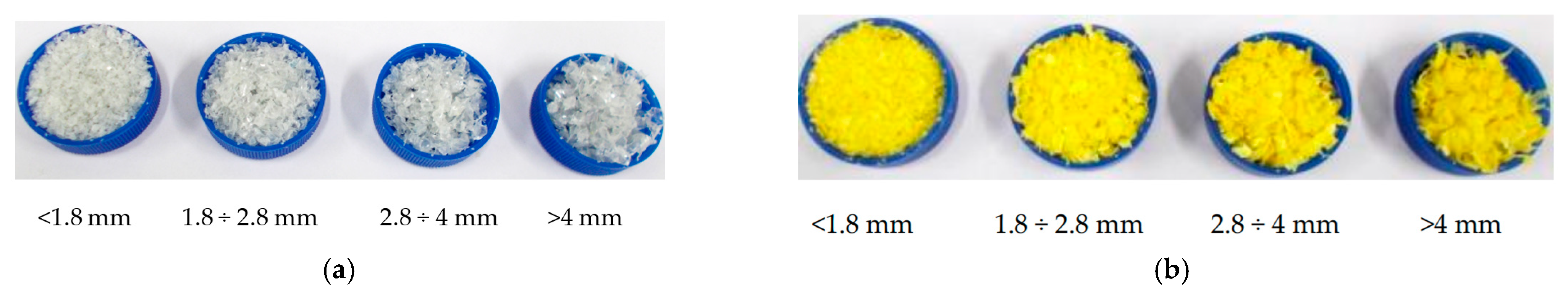
Figure 1. A free-fall triboelectrostatic separator (a) parallel plate, (b) skew plate.
Energies 14 01755 g001
Figure 2. The scheme of a high voltage roll separator.
Energies 14 01755 g002
Figure 3. The granulator (a) with crushing blades and milling modules (b) for grinding the mixed plastic waste.
Energies 14 01755 g003
Figure 4. The view of vibratory sieve shaker (a) and sieves (b) used for the sieve analysis of the mixed plastic waste.
Energies 14 01755 g004
Figure 5. The sieved polymer fractions for electrification process: (a) PET, (b) PE-HD.
Energies 14 01755 g005
Figure 6. The view of tribocharging containers made of: (a) PET-G, (b) PLA/ABS, (c) ASA, (d) PP, (e) assembled container, air filter and airflow in suction head.
Energies 14 01755 g006aEnergies 14 01755 g006b
Figure 7. (a) Dimensions of the container for circulation of the tested mixed polymers and (b) movement of polymer particles during the tribocharging process.
Energies 14 01755 g007
Figure 8. A system for measuring the accumulated charge on particles of (a) PET and (b) PE-HD polymers.
Energies 14 01755 g008
Figure 9. The view of electrostatic separator (a) and stand for the vision system (b).
Energies 14 01755 g009
Figure 10. Charge density per mass as a function of time t of tribocharging in a container for PET with fractions (a) 1.8–2.8 mm and (b) 2.8–4 mm at airflow V = 1.6 cpm.
Energies 14 01755 g010
Figure 11. Charge density per mass as a function of time t tribocharging in a PET-G container for PE-HD with fraction (a) 1.8–2.8 mm and (b) 2.8–4 mm at airflow V = 1.6 cpm.
Energies 14 01755 g011
Figure 12. Charge density per mass as a function of airflow for tribocharging process of (a) PET in the container made of PP; (b) PE-HD in the container made of PET-G for a constant time of the charging process t = 30 s for fraction mass 10 g.
Energies 14 01755 g012
Figure 13. Charge density per mass as a function of airflow for tribocharging process of (a) PET, size of material 1.8–2.8 mm in the container made of PP, ABS, ASA, PLA; (b) PE-HD, size of material 1.8–2.8 mm, in the container made of PET-G, ABS, ASA and PP for a constant time of the charging process t = 30 s for fraction mass 10 g.
Energies 14 01755 g013
Figure 14. The separation result of (a) without charging and after tribocharging for t = 60 s in a container with (b) PET-G, (c) ASA, (d) PP at an airflow of 2.19 cpm.
Energies 14 01755 g014
Figure 15. Electrostatic separator (a), the percentage ratio of PET (gray) to PE-HD (yellow) particles as determined by the image from a dedicated vision system in a container with (b) PP, (c) PET-G, (a) ASA (Sec. I—splitting the mixture of plastics into two sets of materials; Sec. I—percentage share of PET and PE-HD in each box; Sec. III—percentage content of PET and PE-HD in relation to the surface of the boxes).
Energies 14 01755 g015
Table 1. The percentage share of each fraction in the total mass of polymers investigated after grinding and sieving.
Samples<1.8 mm1.8–2.8 mm2.8–4 mm>4 mm
PET~30%~40%~24%~6%
PE-HD~17%~37%~28%~18%
Publisher’s Note: MDPI stays neutral with regard to jurisdictional claims in published maps and institutional affiliations.

