1. Introduction
The increase of energy demand and the concern about the climate change has led to extensive research for renewable energy sources (RES). Hence, microgrids are used to integrate different RES and electrify the remote areas continuously. A microgrid is a small scale power system that consists of loads, distribution generation units (DGUs) and other units for storage which is interconnected with power lines of the grid [
1]. In a DC microgrid, a Buck converter contributes an important role for the efficient performance of the DC microgrid. The main advantage of using DC microgrid over AC microgrid is that it can be operated in grid connected or in islanded mode. DC microgrids [
2,
3,
4] are more in demand than AC microgrids due to its attractive features like availability of converters, interfacing of batteries and DC energy sources. DC microgrid is smaller in installation size and more cost effective as compared to AC microgrid. It requires a lesser number of power electronic converters; hence, the overall efficiency is improved. In addition, AC/DC converters do not require a transformer, which reduces the size of the DC microgrid significantly. An increasing use of DC microgrids is also in trains, ships, charging facilities for electric vehicles [
5]. The occurrence of faults in the physical and communication network layer in the power system can create an imbalance in the overall system. Hence, to maintain the reliability and stability of the overall power system, fault detection forms an important aspect of the overall monitoring systems. For protecting the DC microgrid system from different types of faults, fault detection techniques [
6,
7] are studied and advanced protection schemes are implemented. The possible faults in a DC microgrid can be categorized as actuator fault, sensor fault, component fault and interconnection fault between the subsystems. The detection of these faults in multiple interconnceted DGUs [
8] are explained.
The increased use of sensor network software has drawn many research attentions recently. The quality of the collected data from the sensor readings plays an important role in driving the overall system uninterruptedly. Sensor faults are defined as a data-centric point of view. These faults can be caused by malfunction of hardware or software. The hardware sensor faults can occur due to damage of sensor, short circuits, low battery and errors due to calibration. The software faults can occur due to data logging process and results in abnormal data or short faults. Generally, sensor fault detection methods are categorized into four different types. They are a rule-based detection method, estimation-based method, time series analysis-based method and learning-based method [
7]. The errors due to sensor faults should be detected immediately so that there is no loss of any network information and remedial actions are promptly taken. Most of the existing works on sensor fault detection work well with additive faults, but fail to work with multiplicative sensor faults. A validation of the sensor for a structural system with multiplicative sensor fault [
9] is presented. Single sensor faults are more likely to occur in small scale systems, however, in interconnected systems like a DC microgrid, the occurrence of both voltage and current sensor faults should be considered along with actuator faults, interconnected line faults and component faults.
Sensor fault detections are discussed in grid connected or islanded operation mode using model-based and data driven techniques [
10,
11]. In the model-based fault diagnosis method [
12], a state observer is designed to generate the residuals and a common threshold is selected. An alarm will be triggered when the generated residual exceeds the threshold [
13]. In model-based fault detection, an identification method for switching power converters is designed using a model-based state estimator method. This type of approach is used to detect arbitrary faults in the sensor and components of the switching power converters in a nanogrid. The faults in the components, actuators and sensors of a DC microgrid are modeled by using additive terms in the state space and measurement equations. However, due to fluctuations in load and parameter uncertainties, the generated residuals may trigger a false alarm and accurate detection of fault will not be accomplished. Hence, to encounter this issue, different techniques like
[
12,
14] criteria can be used for the design of observers. This criteria gives a balance trade off between the robustness of the residual and sensitivity from the faults to the generated residual in the presence of disturbance. This criteria can also be used as an attenuation of disturbance and thus enhance the robustness and stability of the system. Similarly, in [
15], a bank of Linear Parameter Varying (LPV) observers are designed to detect, estimate and diagnose faults on every subsystem of the microgrid. The solutions of those observers are found by the
/
sensitivity minimization problem which can guarantee robustness towards load disturbance and insensitivity to measurement noise. However, this criteria is mostly dependent on frequency domain aspects and provide less information about the stability condition of the observer. In [
16], a wireless sensor network (WSN)-based wind turbine is considered for discussion of sensor fault detection and isolation. In [
17], three types of communication delays and the states of the inverter in the microgrid are estimated using sliding mode estimation technique.
In [
18], a linear observer based on Kalman Filter is designed to generate the sensor fault residuals and hence detect the faults. This method uses online recursive model estimation to detect a normal and a faulty sensor. However, the changes of load current in the power distribution decreases the robustness of the system performance. In [
19], a sliding mode observer (SMO) for fault detection is designed based on the current and measured voltage of the capacitor in a modular multilevel converters. Adaptive SMO-based fault tolerant control strategy is designed to reject the influence of faults in the pitch of a wind turbine in [
20]. Similarly, in [
21], multiple SMO is used for the estimation of state and unknown input for a class of MIMO nonlinear systems. In [
22], a sensor fault was diagnosed in an electric traction pulse width modulated rectifier based on SMO. However, the SMO approaches based on first-order approaches suffer from the chattering effect caused due to measurement noise and unknown loads. Hence, to reduce the noise induced chattering, a higher order sliding mode observer (HOSM) [
23,
24] based on Supertwisting Algorithm (STA) has been used. In [
25], sensor faults are considered in a nonlinear aircraft model and estimated using a second order sliding mode observer and active fault tolerant control scheme is used. This observer can guarantee finite time convergence, reconstruct the unknown input and also provide robustness against bounded uncertainties. In [
8], event triggered STA is used in sliding mode controller design for suppressing the matched and unmatched uncertainties in a grid connected and islanded mode microgrid. In [
26], possible faults like actuator fault, sensor fault, component faults and interconnected lines fault are detected by using a distributed observer along with a hierarchical controller in a DC microgrid. Motivated by the aforementioned works, an HOSM observer is designed for sensor fault detection and attenuation of unknown loads in the DC microgrid.
In this proposed work, two HOSM observers based on STA are designed for every DGU to estimate current and voltage and generate the residuals for detection of faulty sensors. Two separate observers are designed for estimation of the current and voltage dynamics for each DGU. The selection of threshold plays an important role due to the interconnections of DGUs and for multi-fault occurrence scenarios. Multiple simulations are performed under on load and off load conditions with a multiplicative sensor fault for various DGU configurations and combinations of sensor faults. The changes in the generated residuals are observed and a common threshold for fault detection is finally identified for the DGUs. Simulations for various fault scenarios are conducted to validate the approach. The rest of the paper is organized as follows: The problem formulation is discussed in
Section 2.
Section 3 covers the HOSM observer design and
Section 4 follows up with fault detection.
Section 5 presents the simulation results whereas the discussion is provided in
Section 6. Finally
Section 7 concludes the paper.
2. Problem Formulation
The DC microgrid model with
N interconnected DGUs is shown in
Figure 1. The DGUs in a DC microgrid are interconnected via power lines. The DGUs represent the nodes,
and the power lines represent the edges,
of a graph
which represent the microgrid. The interaction between the neighboring DGUs
i and
j can be represented by an adjacency matrix
where
is the possibility of interaction and
T represents the topology of the power system network. If there exists an interconnection between the DGUs
i and
j,
otherwise
. Applying Kirchoff’s voltage and current law to the electrical scheme in the block diagram as shown in
Figure 2, the dynamics of the
ith DGU can be represented as follows:
where
,
,
,
,
,
and
denote the load voltage, current generated, capacitor of the shunt, inductance, resistance, resistance of the line and overall current demand, respectively. The system states are represented by
,
and the input is represented by
. The point of common coupling (PCC) voltage of the DGU
i’s neighbors can be represented by
and
denotes the conductance of the power line connected to the DGU
i with its neighboring DGU. The DGU consists of a source voltage, which is a renewable resource, and the Buck converter acts as a supplier of local load connected to the PCC through a series of LC filters. The DC loads are unknown and can be treated as current disturbance
.
The state space equations of the dynamics of each DGU can be represented as follows:
where the local states can be represented by
, control input can be represented by
, unknown input can be represented by
, unknown disturbance can be represented by
and the output by
with
as the output matrix. The disturbance matrices can be represented by
and
. The DC microgrid state model can be represented as follows:
A local primary controller is designed to ensure asymptotic stability for an augmented system. The primary controller, which is a decentralized sate feedback controller, regulates the voltage at each PCC and ensures that the microgrid is stable. An integrator term is used in the primary controller and its dynamics can be represented as follows:
where
is the reference voltage and
represents the secondary control input. The state feedback controller
can be represented as
, where
and it should ensure that
is Hurwitz. The state matrix can be represented as
and
is a design parameter chosen using the Linear Matrix Inequality (LMI) conditions [
27]. The DGUs can supply uninterrupted loads only when the proportional current sharing among the DGUs is ensured. Hence, at the steady state condition, the sharing of load current is proportionally done among all the other DGUs. Thus a secondary controller is designed for the
ith DGU as follows:
where
represents the integral coefficient of the
ith DGU. The stability of the controller can be proved similar to [
28].
The objective of the paper was to design an HOSM-based observer for current and voltage estimation for the system dynamics (1)–(2) for fault identification. Two separate observers are designed for estimation of the current and voltage dynamics for each DGU i that will be discussed in the later sections. The selection of threshold plays an important role due to the interconnections of DGUs and multi-fault occurrence scenarios. In this paper, only a multiplicative sensor fault is considered for sensor fault detections. A hierarchical control scheme is used to maintain stability of the subsystem with an equal distribution of current among the DGUs. A decentralized primary controller is designed which guarantees the asymptotic stability of the connection between the DGUs. A secondary controller is also designed to ensure equal sharing of current between the DGUs and common value of average voltage is maintained in all the PCCs.
3. HOSM Observer Design and Fault Detection
In this section, an HOSM observer [
29] is designed to estimate the voltage and the current of the DGUs. The HOSM observer for voltage estimation can be designed by considering the current to be a known quantity and the voltage as an unknown quantity. The HOSM observer for estimating the unknown voltage from the current dynamics can be designed as follows:
where
,
,
,
, denote the corrective term of the super twisting (STA) [
30], inductance and resistance of the power lines and control input to the Buck converter, respectively. The estimation error,
, is defined as follows:
where
and
are the estimated and actual currents, respectively. The corrective terms of the STA can be designed according to [
31], as
where
,
and
are the properly chosen positive gains. The sliding mode error dynamics can be represented in the following form:
where
represents the perturbation terms and can be expressed in the form
. Hence, the boundedness of the voltage can be assumed as
and
, where
and
denotes the positive bounds of the perturbations. Based on the above boundedness conditions, the error convergence to zero can be proven to be asymptotic in finite time
and the proof is similar to [
31]. Thus, it can be seen that
in finite time. The finite time convergence of the sliding surface, i.e.,
to the origin can be proved as shown in [
30]. The positive gains
,
and
based on STA are designed as [
32]. After the convergence of the sliding surface to the origin, the voltage of the
ith DGU can be reconstructed as:
The HOSM observer based on STA for the estimation of current can be designed as follows:
where
is the corrective term of the STA.
,
,
,
and
are the capacitance, current in the DGU, load current, resistance between the interconnected DGUs and voltage of the interconnected DGU, respectively. The current estimation error can be defined as
. The robust HOSM terms are given as:
where
,
and
are the positive chosen gains designed similar to the voltage observer. The estimation error dynamics can be written as:
The boundedness of current,
, can be established with the positive constants
and
as
and
. Considering this condition, the finite time convergence of
can be ensured similar to [
31]. Hence, the estimation of current can be achieved as:
5. Simulation Results
In this section, the simulation results are presented to demonstrate the efficiency and robustness of the HOSM observers for fault detection in a DC microgrid. The specification of the electrical and line parameters similar to [
26] for DGUs are considered in
Table 1 and
Table 2. A microgrid is comprised of 5 DGUs as shown in
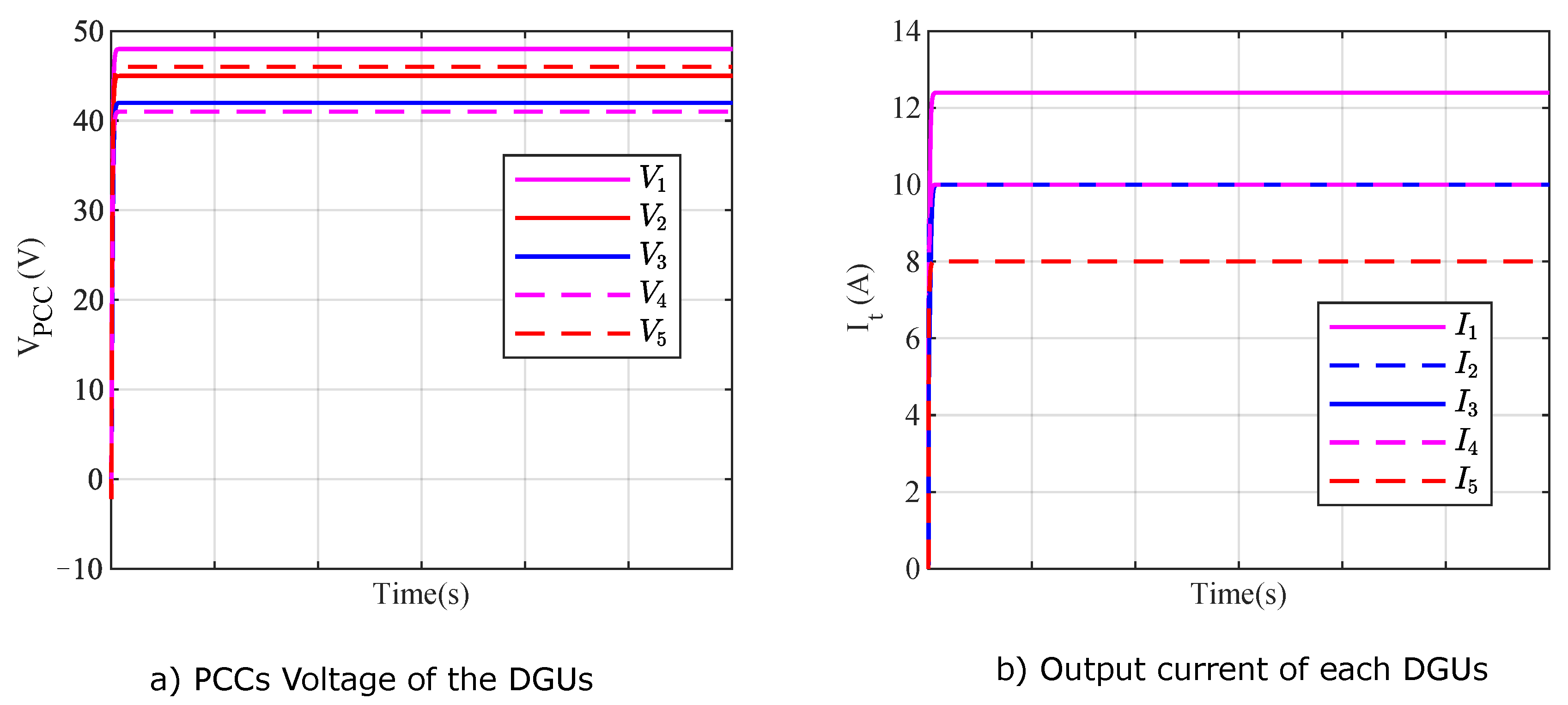
Figure 3. The HOSM observer based on Supertwisting algorithm (STA) is designed to generate the residuals of the faulty sensors. To check the robustness of the proposed methodology, a band limited white noise of 0.5 dB is considered for overall microgrid. The primary controller output of each DGU is shown in
Figure 4 and the response of the HOSM observers for each DGU with healthy sensors is shown in
Figure 5. Multiple cases of sensor faults are considered for analysis and graphically represented in this section.
Threshold Selection
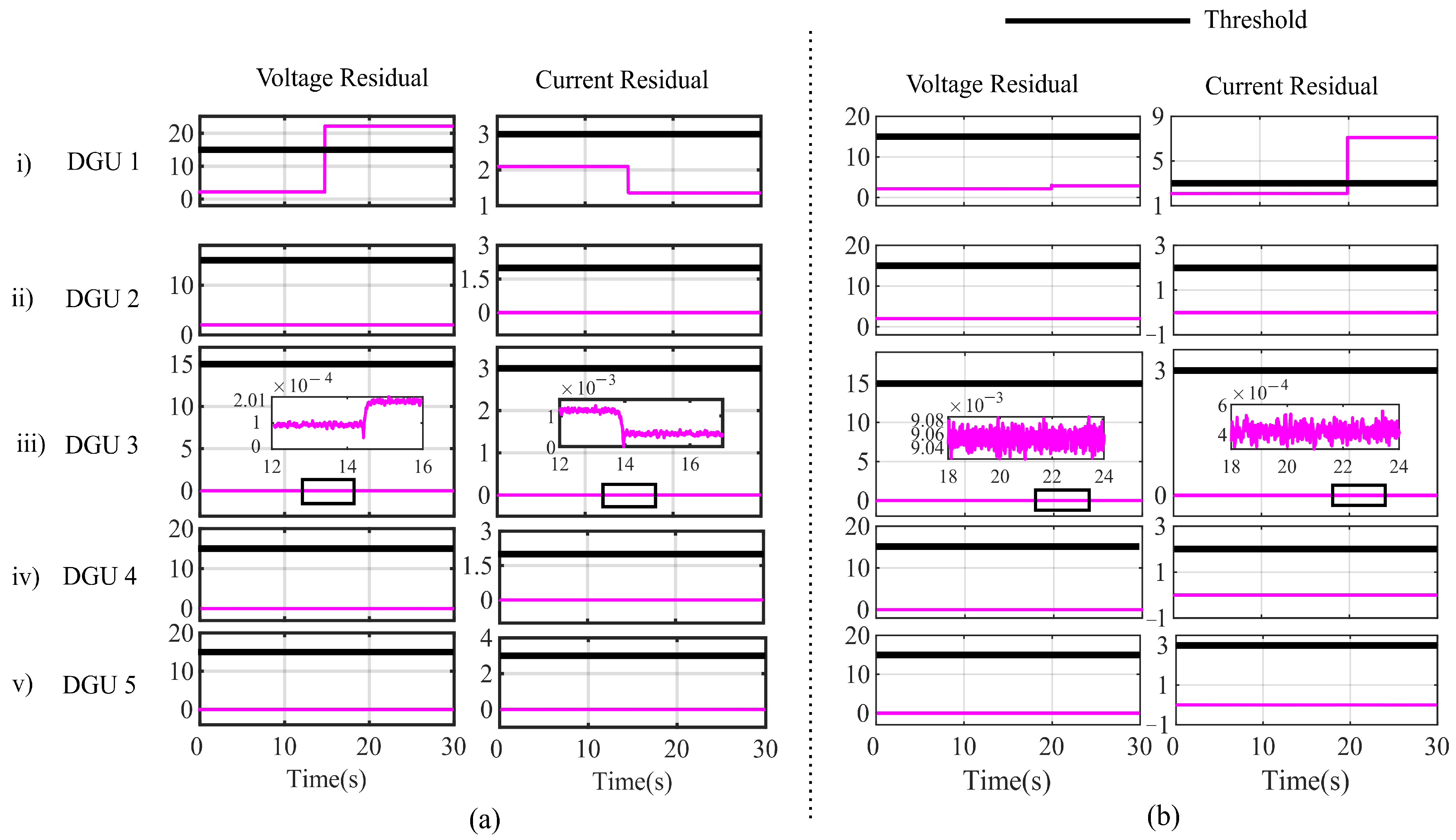
In this subsection, the selection of the threshold for single and multiple sensor faults under different load conditions are evaluated. First, voltage sensor faults are considered for each DGU with an unknown load. Under this condition, the residuals of the estimated states and the faulty states are considered. Secondly, a current sensor fault is considered in all the DGUs at different time instants and a random noise of 1% to 3% is introduced in the faulty sensor. Due to current sensor fault in the DGUs, the voltage sensor also gets affected. The generated residuals are checked for all the current sensor faults. Thirdly, multiple sensor faults in a DGU and its interconnected DGUs are considered. The residuals of the faulty sensors are observed. After undergoing multiple simulations, the threshold for the voltage and current sensor faults are selected for accurate fault detection in a DC microgrid. Several rounds of simulations under different load, noise conditions are conducted to statistically validate the threshold values. After extensive analysis, the threshold values for the voltage and current sensor fault detections are identified as 15 V and 4 A, respectively.
Case 1: Voltage sensor fault in a single DGU
In this case, a voltage sensor fault occurs in a single DGU and the response of all the DGUs are presented. As shown in
Figure 5a(i), a voltage sensor fault occurs in DGU 1 at t = 15 s. Before fault, the voltage residuals lie below the threshold, however, after the occurrence of fault, the voltage residual in DGU 1, cross the threshold. A change in the residual of DGU 1 can be seen after t = 15 s. As DGU 1 is interconnected to DGU 3, there is a change in residual of the respective voltage and current sensor. However, the voltage and current residuals of DGU 2, DGU 3, DGU 4 and DGU 5 lie below the threshold. Similarly, when there is a voltage and current sensor fault in DGU 2, DGU 3, DGU 4 and DGU 5, the interconnected DGUs also get effected. The residuals of the faulty sensors cross the threshold, however, the residuals of the non faulty sensor lie below the threshold. From these observations, the faulty sensor can be detected immediately and hence the overall system can be protected.
Case 2: Current sensor fault in a single DGU
In this case, a current sensor fault occurs in each DGU and the responses are observed. In
Figure 5b(i), a current sensor fault occurs in DGU 1 at t = 20 s. The current residual cross the threshold after the occurrence of fault. At this instant, the fault can be detected using the fault detection algorithm. The effect of current sensor fault can be seen in the voltage sensor residual of DGU 1, however, it remains below the threshold. As DGU 1 is interconnected to DGU 3, the effect of the faulty current sensor can be seen in
Figure 5b(iii). Similarly, when there is a current sensor fault in DGU 2, DGU 3, DGU 4 and DGU 5, the residuals of the faulty current sensors cross the threshold, indicating that a fault has occurred. Hence, the residual-based fault detection algorithm can differentiate a faulty sensor from a non faulty one.
Case 3: Voltage and current sensor faults
When both voltage and current sensor fault occurs in the DGUs of the microgrid, the respective voltage and the current sensor fault residuals cross the threshold and the flag raises at the instant of fault. The flag raises to 1 when a fault is detected and remains at 0 when there is no fault in the sensors. In
Figure 6, a multiplicative voltage sensor fault
occurs at t = 15 s and for a current sensor
occurs at t = 20 s. The voltage and current sensor faults are marked as
and
, respectively. At the instants of fault occurrence, the flags,
and
of the voltage and current sensor fault, respectively, raise to 1 as shown in
Figure 6(ii). The changes in the interconnected DGU 3 are shown in
Figure 6(iv). It can be seen that the residuals of the voltage and the current sensors in non-faulty DGUs lie below the threshold. In
Figure 7a,
occurs at t = 15 s and
occurs at t = 20 s. Similarly, in
Figure 8a, the voltage and current sensor faults occur in the DGU 3 of the microgrid which is interconnected to DGUs 1, 2 and 4. The voltage fault in DGU 3 occurs at t = 10 s and the current fault occurs at t = 15 s. The flag raises to 1 at that instants, indicating the occurrence of faults. The residual changes of the interconnected DGUs is portrayed in
Figure 8(iii)–(v), respectively. Simulations are also done by considering 10% of load changes and introducing a random noise of 2% in the dynamics of the DC microgrid. A delay of 3 ms is also considered to check the robustness of HOSM observer-based sensor fault detection as shown in
Figure 9. Faults are also considered in both the voltage sensors in DGU 1 and DGU 2 and the change in the residuals for the respective voltage and current sensor in all the DGUs is shown in
Figure 10.
6. Discussion
The proposed method is analyzed with different sensor fault conditions and the results show that the proposed approach is successful in identification of single and multiple sensor faults in the interconnected DC microgrid system. In the voltage and current sensors, a multiplicative sensor faults with different values of and is considered in DGUs under various load conditions. A single sensor and multiple sensor fault scenarios are considered and multiple simulations are done to select a proper threshold for fault detection.
A random noise of 1–2% is considered along with the voltage and current sensor faults in all the DGUs and simulations are performed to check the residuals. It is seen that the residuals of the faulty sensors in the respective DGUs and its interconnected DGUs lie below the threshold. The optimal gain selection in HOSM significantly effects the residual-based fault detection performance of the DGUs. An incorrect choice of observer gains can raise the residual above the threshold thereby creating a false alarm of fault. To mitigate this issue of false alarm, the proper selection of observer gains is important. However, to check the robustness of the proposed methodology, a random noise of 1–3% is introduced in DGU 1 and DGU 2. Optimal gain selection multiple voltage sensor faults occur in both the DGUs at t = 15 s and t = 20 s as shown in
Figure 10(iii). At the instant of faults,
and
, the voltages in each residual cross the threshold. The impact of the voltage sensor faults of DGU 1 and DGU 2 in its common interconnected DGU 3 can be seen in
Figure 10. The impact on the residuals of DGU 4 due to voltage sensor fault in DGU 2 is shown in the zoomed portion in
Figure 10(iv). Thus, it can be ensured that the proposed method is robust to a noisy environment.
In this work, a constant delay between the Buck converter and the local controller is used to check the impact on the overall system. A delay of 3 samples equivalent to 0.03 s is considered in the voltage sensor of the DGU 1. It can be observed that the estimated voltage of the HOSM observer tries to track the original voltage even in the presence of delay. Similarly, the influence of the voltage sensor delay can be seen in the estimated current of DGU 1. As DGU 1 is interconnected to DGU 3 of the microgrid system, the estimated voltage and current tracks the actual voltage and current after a certain time delay. This proves the robustness of the HOSM observer. If the delay is increased then the system becomes unstable and the fault detection is further delayed. It can be seen that the voltage sensor fault is detected at t = 15.03 s for the three samples’ delay as shown in
Figure 9.
A change in 10% load in all the DGUs show a change in RMSE % of 0.6%, 0.11%, 0.005%, 0.0126% and 0.0288% in DGU 1-DGU 5 respectively from its nominal value. Similarly, the load changes of 15–20% are introduced in the DGUs and simulated. The HOSM observer is used to generate the residuals for faulty sensors. The faults with the said load conditions can be detected when the residuals cross the threshold. However, a change in 25% of the load causes a large deviation in the errors of the sensor estimations and the fault is not detected with the selected threshold. The RMSE values for 25% load changes in DGU 1-DGU 5 are 1.3469%, 1.7508%, 1.9951%, 1.5871% and 1.7369%. To test the robustness of the proposed method, , and of the random noises are added to the actual measured signals. For the case of noise, the proposed method was unable to detect the fault with the selected threshold. The proposed methodology is sensitive to higher sensor noise levels.


