Abstract
Concern over the asymmetric phenomena in the core region has increased considering safety issues that are highly possible to reduce the thermal margin significantly in nuclear power plants. Since the seized reactor coolant pump (RCP) accident of an advanced power reactor 1400 (APR1400) can be regarded as a representative core asymmetric event with respect to core inlet flow, the departure from nucleate boiling ratio (DNBR), which is a regulatory acceptance criterion in nuclear safety, should be evaluated with consideration of the uncertainty range of the core inlet flow reflecting the actual geometry. This study investigates the DNBR quantitatively in the entire fuel assemblies in the core using several codes for system behavior, computational flow dynamics, sub-channel analysis, and uncertainty evaluation. Based on the results from a system thermal-hydraulic analysis of a seized RCP accident of APR1400, this study presents the uncertainty range calculated by computational fluid dynamics on the asymmetry of the core inlet flow. Damaged fuel rods are quantitatively identified through a sub-channel analysis, which presents statistic relevance to obtain the DNBR at 95% reliability and 95% accuracy level. Additionally, an optimized evaluation methodology of a non-loss of coolant accident (non-LOCA) is realized by several nuclear codes.
1. Introduction
Non-loss of coolant accident (non-LOCA) safety analysis methodology has been evolved from a deterministic methodology to an optimized evaluation methodology to ensure adequate safety margins as regulatory acceptance criteria have been strengthened around the world after the Fukushima nuclear accident [1,2]. The optimized evaluation methodology is overall framework of deriving uncertainties in critical physical phenomena affecting acceptance criteria during the transient of an accident and statistically quantifying the impact on the accident’s outcome [1,2,3]. One of the important physical phenomena in the non-LOCA area is core asymmetry, and a seized reactor coolant pump (RCP) accident can be regarded as a representative transient from the point of view of the core inlet flow.
According to the final safety analysis report (FSAR) of advanced power reactor 1400 (APR 1400) [4], a seized RCP accident leads to a rapid reduction of the flow rate of the core inlet immediately after the accident, thereby increasing the temperature of the core inlet. Currently, the rapidly reduced core inlet flow rate has an adverse effect on the regulatory acceptance criterion, the departure from nucleate boiling ratio (DNBR) [5]. However, it has been hypothesized that the flow path in the loop with the seized RCP is fully blocked in both directions at the same time of accident. Thus, the FSAR result appears to have failed to fully consider the core inlet flow asymmetry because reverse flow was not considered [4].
There have been no experiments in a large facility simulating core asymmetry, but such experiments have been carried out in small-scale facilities, such as MATIS-H experimental facility [6]. Accordingly, there is difficulty in applying the obtained data directly to actual plant design. As an alternative, some researchers have reported that a computational fluid dynamics (CFD) interpretation can provide information about the phenomena in the core lower plenum [7,8,9,10].
In order to investigate the appropriateness of the lower core support plate (LCSP) design, Kim et al. [11] and Bae et al. [12] calculated the core inlet flow rate in an integral type reactor, system-integrated modular advanced reactor (SMART), using CFD. They concluded that the CFD showed asymmetry within about 2.3% of the conservative conditions through a sensitivity analysis of the turbulence mode. They also found that the degree of core flow asymmetry was fairly the same for the different mesh sizes, Reynolds numbers, and turbulence models. Jeong and Han [13] calculated the distribution of the core inlet flow using CFD under steady-state conditions of the Korea standard nuclear power plant (KSNP). They found that the non-uniform flow was observed below the cold-leg inlet nozzle. They concluded there was a standard deviation of about ± 20% on the average flow rate. Sun et al. [14] carried out optimization of a flow mixing chamber by estimating the temperature and pressure at the core inlet using CFD. They found that the operation of a steam generator (SG) under low power conditions could cause core asymmetry on the coolant velocity and temperature owing to large hole size.
Additionally, there have been some activities to evaluate nuclear safety precisely employing the development of an integrated code with the capability to simultaneously analyze parameters ranging from fuel performance to containment response or using a coupling method of several codes [15,16]. Related to these activities, the Korea Atomic Energy Research Institute (KAERI) [17] has been developing a code that calculates the system and sub-channel behaviours. However, the code needs to be validated by experimental data.
According to the results of the literature survey, the asymmetry of the core flow rate is strongly influenced by the real geometry. Therefore, the CFD analysis should be used to model the actual geometry. Furthermore, almost all the current findings are the results of the distribution of flow rates in steady-state operation, and there are still difficulties to use the currently developed technology directly in a seized RCP transient analysis. In particular, because it has not been possible to conduct a simultaneous analysis from the sub-channel to the system behaviours at the current technical level, the present study uses a method of sequentially linking the codes for the system analysis, CFD, and sub-channel analysis reflecting uncertainties.
The aims of this study are to determine the uncertainty range on the asymmetry of the core inlet flow in a seized RCP accident of APR1400 and to quantify failed fuel rods from the viewpoint of the regulation. An optimized evaluation methodology of a non-LOCA was established based on several nuclear codes. The inlet flow distribution on 241 fuel assemblies was investigated and a statistic uncertainty range was obtained based on the thermal-hydraulic system behaviors of a seized RCP accident. In addition, the DNBR was specifically evaluated by considering realistic fuel thermal power to understand how many of the damaged fuel rods described in the FSAR failed and whether there was conservatism.
2. Analysis Method for DNBR Evaluation
2.1. System Description
Figure 1 shows the nodalization of APR1400 under investigation. The APR1400 includes a reactor vessel and a reactor coolant system (RCS) with two closed loops connected in parallel. The reactor core consists of 241 fuel assemblies with a core thermal power of 3983 MWt. Each loop has one SG, two RCPs, and a pressurizer (PZR) connected to one of the RCS loops. The RCS operates at a nominal pressure of 158.2 kg/cm2A. The reactor coolant enters the reactor vessel, flows downward between the reactor vessel shell and core barrel, flows up through the core, leaves the reactor vessel, and flows through the tube side of the two SGs where heat is transferred to the secondary system. The RCPs return the reactor coolant to the reactor vessel.
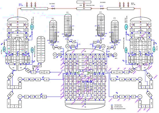
Figure 1.
Nodalization of APR1400.
2.2. Analysis Method
This study evaluated the asymmetric events with at least four codes: system code, CFD software, sub-channel analysis code, and uncertainty tool. First, the system behaviour of asymmetric events was analyzed using a system code, multi-dimensional analysis for reactor safety—KINS standard (MARS-KS) [18]. The main outputs were the mass flow rate, temperature, and pressure in the cold leg and hot leg, where it is essential to evaluate asymmetric phenomena in the core region during a transient. Second, a commercial CFD code was used to calculate the distribution of the mass flow rate and temperature at the core inlet based on the system results from MARS-KS. This step was able to identify the three-dimensional distribution of coolant at the core inlet. It played a key role in investigating the pattern of the core flow distribution and the range of uncertainty of the flow rates. The uncertainty tool generated 124 inputs for sub-channel analysis code to obtain the DNBR at 95% reliability and 95% accuracy level over the uncertainty range and form [19,20]. Finally, the sub-channel analysis code numerically calculated the DNBR based on the uncertainty range with respect to the asymmetric mass flow rate and temperature. Figure 2 shows the code system and flow of information to evaluate the DNBR in this study.
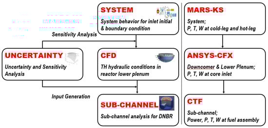
Figure 2.
Code system and flow of information for DNBR.
3. DNBR Evaluation of Seized RCP Accident Considering Uncertainty of Core Flow Asymmetry
According to the seizure of an RCP rotor, the core flow rapidly decreased to the value that would occur with the operation of only three RCPs. The rapid reduction of the primary coolant flow rate caused an increase in the average core coolant temperature, a corresponding reduction in the margin to DNB, and an increase in the primary system pressure. The reactor heat was removed by means of natural circulation in the reactor coolant system according to the coast down of the intact RCPs. During the progress of decreasing the reactor coolant flow, the primary parameter of concern is the minimum DNBR [4,5]. This parameter determines whether the fuel damage can be anticipated.
The major factors for decreasing local DNBR are as follows: decreasing coolant flow, increasing coolant temperature, decreasing coolant pressure, and increasing local heat flux. The above operating parameters were used as initial conditions for system behaviors based on the sensitivity study to ensure conservatism. Dissimilar to operating parameters, core flow asymmetry is one of the important physical phenomena related to momentum change in the lower plenum. Thus, it was necessary to evaluate the degree of core flow asymmetry in detail using uncertainty methods [21].
3.1. System Behavior
Apart from that one RCP was seized, loss of off-site power was assumed according to the sequence of events described in the FSAR. This was also considered in the present calculation. In addition, the initial and additional conservative conditions were consistent with those of the FSAR. The steady-state results were properly obtained by the MARS-KS code with a maximum deviation of 2.1% in the steam pressure [22,23].
Figure 3 shows the mass flow rate transient up to 1800 s in each loop. The reactor coolant flow rate showed significant core asymmetry between the affected and unaffected loops. Moreover, a large amount of reverse flow was observed for several seconds in the loop where the RCP was locked, in contrast to the FSAR assumption. However, the mass flow rate was temporarily increased in the unaffected loop due to the high driving force compared to the affected loop.
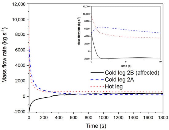
Figure 3.
Mass flow rate in each loop.
Figure 4 presents the total mass flow fraction between the calculation and FSAR results. The FSAR results were identified as being more conservative than the regulatory calculation in terms of the total mass flow rate into the core inlet.
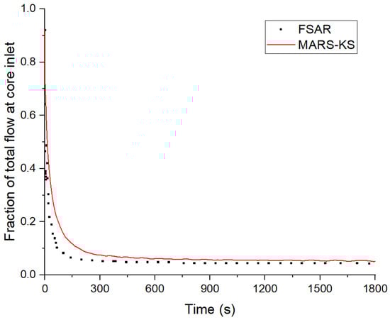
Figure 4.
Comparison of total mass flow rate.
3.2. Asymmetric Distribution of Core Flow
This study also conducted a three-dimensional CFD analysis focused on the reactor vessel of the APR1400 applied as boundary conditions of the cold and hot legs based on the sensitivity study of the system behaviour. It is realistically impossible to simulate the whole transient period of a single RCP rotor seizure accident by the CFD code alone. The minimum DNBR is known to have occurred between 1 and 4 s after the accident. In this study, unsteady CFD simulations were conducted on the reactor internal flow up to 5 s after the RCP rotor seizure, and the flow rate distribution was evaluated at the core inlet. Figure 5 shows the computational domain of the reactor vessel used in this study. Table 1 presents the initial conditions for a transient based on the results from the steady-state of the APR1400 reactor using the one-dimensional MARS-KS code.
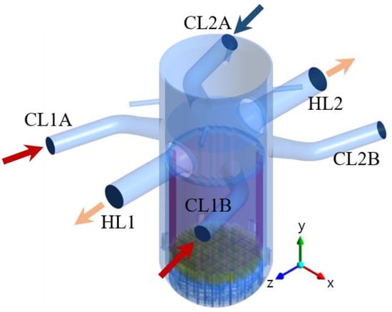
Figure 5.
Schematic domain of reactor vessel of APR1400 (CL: cold-leg, HL: hot-leg).

Table 1.
Initial transient conditions for CFD calculation.
In the CFD study, a porous medium for fuel assemblies was applied to efficiently calculate the flow field, which was predicted to have almost no effect on the flow at the lower plenum of the reactor. The unsteady Reynolds-Averaged Navier-Stokes (RANS) equations were solved using the ANSYS-CFX code. The standard k-ε model was applied with consideration of the turbulence [24].
The geometries of the structures inside the reactor vessel should be considered to perform a CFD analysis on the thermal flow mixing in the APR 1400 reactor. The internal structures located in the upstream of the reactor core support the fuel assemblies and distribute the coolant flow uniformly. Thus, the coolant flow in the lower plenum exhibits complex thermal-hydraulic characteristics owing to these structures. In this study, the geometries of the downcomer, ICI nozzles, and lower support structures in the reactor vessel were considered to analyze the flow mixing characteristics in the lower plenum. The upper plenum for the reactor vessel, fuel assemblies, and bypass flow of the reactor core was not considered because it has minimal effects on the flow and temperature distribution at the reactor core inlet and the thermal flow mixing at the lower plenum.
The tetrahedral mesh was adopted for the internal flow region, and the prism mesh was generated near the wall to enhance the accuracy of the wall model. The upper plenum and fuel assemblies were considered as a simple, bulky volume (porous domain). Porosity and resistance models were applied to the porous domain to estimate the velocity and pressure drop in the upper plenum and fuel assemblies.
Figure 6 shows the number of fuel assemblies on the flow rate distribution at the core inlet. During the RCP rotor seizure event, the flow distribution in the reactor became slightly uniform as the coolant flowed toward the core. However, the flow rates in some fuel assemblies were lower than those in the normal operation conditions. The minimum flow rates were calculated as 65% and 66% in two assemblies at around 0.4 s.
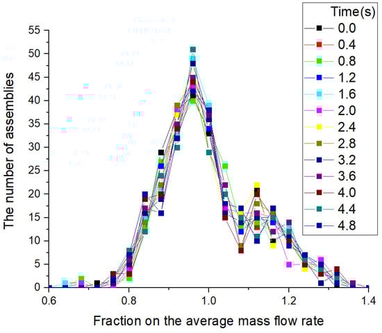
Figure 6.
The distribution of the core inlet flow for each assembly.
Figure 7 shows the range of core inlet flow over transient time to determine the uncertainty of the core flow asymmetry. As final values of the uncertainty, a mean value of 1.0 and a standard deviation of 0.230 were identified with a normal distribution. At 2.1 s, when the DNBR showed a minimum value from the system results, the fraction range of core inlet flow calculated by the CFD was from 0.699 to 1.325. Compared with the FSAR results of APR 1400, the total inlet flow into the entire core was more conservative than that of the MARS-KS results, because the FSAR assumed there was no flow in both directions as soon as the transient initiated. However, given the reverse flow rate bypassing the core immediately after the accident, the MARS-KS results could be smaller than the FSAR values with respect to the inlet flow to a fuel assembly. In other words, when the reverse flow of core inlet flow was more realistic, it could be concluded that the DNBR at fuel assemblies of the FSAR was likely to be less conservative.
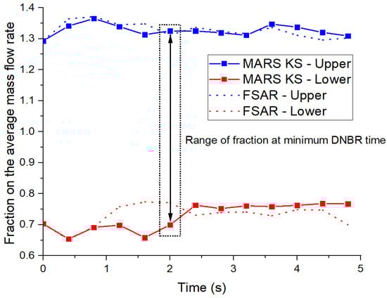
Figure 7.
Minimum DNBR for five transient seconds using MARS-KS.
Based on the uncertainty range predicted by CFD, the one side Wilks [19] formula was applied, and the uncertainty tool produced 124 input data to achieve 95% reliability and 95% accuracy of the DNBR. The reason for the use of the one side Wilks formula was that a smaller core inlet flow led to a decrease of the DNBR. The detailed theory can be found in the reference [19]. Therefore, 124 inputs using the uncertainty range on the core inlet flow would be used for the calculation of the sub-channel, with results in meaningful statistics.
3.3. Sub-Channel Analysis for DNBR
In this study, the detailed DNBR is determined by a sub-channel analysis, and therefore the coolant boiling in rod arrays two fluids (CTF) sub-channel analysis are described in more detail. Detailed modelling is required to precisely calculate many fuel rods and multiple sub-channels in one fuel assembly. One of the most important phenomena could be crossflow in each sub-channel due to a lateral pressure difference and the effect of grid spacers, including mixing vanes, turbulent mixing, and void drift [6,25,26].
Within the sub-channel code, three main conservation equations are solved for each phase (mass, momentum, and energy). For each of the following conservation equations, the subscript k is used to denote the phase.
Mass
Momentum
Energy
The final term in the right-hand side of Equation (1), , is the source term representing grid-directed crossflow effects. The definition of this source term is shown in Equation (4) and represents a lateral mixing factor. Lateral mixing factors were provided at each axial location from the available experimental data [6,27], which were used for each gap in the sub-channel model.
The turbulent mixing model allows the user to supply a multiplicative factor for the two-phase component of turbulent mixing corresponding to in Equation (1), in Equation (2), and in Equation (3). They are defined in the sub-channel code for a transverse mass flow caused by turbulent mixing as follows:
The grid-induced turbulent mixing model is applied by modifying the mixing coefficient, .
This factor is a function of the distance downstream of the grid y-direction. The single-phase mixing coefficient values were determined using the CFD results [28,29], which were analyzed utilizing the heat balance method between adjacent sub-channels of a five by five fuel lattice of APR1400. The detailed information can be found in the reference [29,30].
APR1400 consists of 241 assemblies that have 16 by 16 fuel rods and 289 sub-channels. The active core length was 3.81 m nuclear fuel equipped with nine grid spacers and five guide tubes. Figure 8 illustrates a three-dimensional overview of the 289 modelled sub-channels.
Figure 8.
Three-dimensional overview of a fuel assembly.
The primary considerations used in the sub-channel modelling were as follows: (1) the geometry and heating surface were exactly copied as they were in the case of a single fuel assembly. The area of the sub-channels was divided according to locations such as the centre, corner, and edge. Four guide tubes and one support tube without heat generation were modelled. (2) The crossflow modelling considered forced crossflow with support grids, forced mixing with mixing vane influence, and turbulent mixing with turbulent influence. (3) It was assumed that the lateral flow by both the pressure difference along the radial direction and the two-phase bubble drift was negligible. This was because the upward flow was so dominant that lateral flow could be negligible.
This sub-channel analysis was conducted at the time when the minimum DNBR occurred. The DNBR was evaluated for the range of uncertainty on the core inlet flow. The other initial conditions with the exception of the axial and radial power distributions were derived from the MARS-KS results. Table 2 shows the initial conditions obtained from MARS-KS for the sub-channel analysis.
Table 2.
Initial conditions for sub-channel analysis.
The power distribution of the entire core fuel assemblies of the APR 1400 was investigated and divided into 14 groups to provide crucial thermal boundary conditions for the sub-channel analysis. Figure 9 illustrates the number of assemblies on the relative power density for 14 groups. The number of fuel assemblies does not show normal distribution. Thus, the thermal boundary condition to obtain 124 samples for the power range was assumed to be uniformly distributed to ensure conservative results.
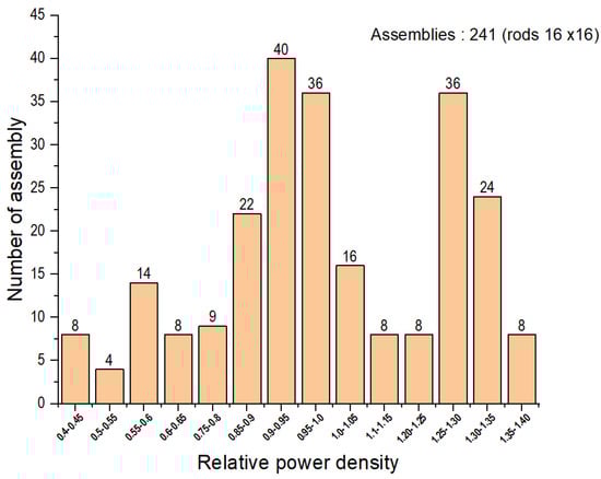
Figure 9.
The number of assemblies according to the relative power density.
Figure 10 shows the calculated DNBR according to the length of the fuel assembly when both the distribution of the core inlet flow rate and the uniformed power distribution of 124 inputs to all fuel assemblies were applied. The DNBR properly reflected the thermal power trend. Six cases including 3rd DNBR did not meet the acceptance level of 1.29. Furthermore, they failed to satisfy the acceptance criteria at higher elevations above 300 cm. One can observe that the larger the thermal power was, the faster the DNBR occurred. As shown in Figure 10, it was expected that there would be several damaged fuel assemblies. However, this result did not show the exact place where the damaged fuel assemblies were located.
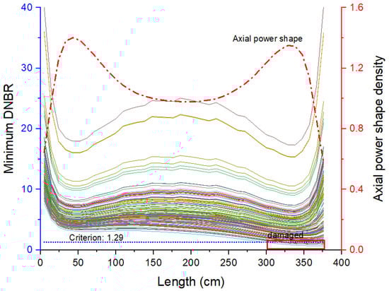
Figure 10.
The minimum DNBR on the axial length of 14 assembly groups (124 runs).
To figure out the exact locations and number of damaged fuel assemblies, the minimum core flow rate that did not cause the DNBR was analyzed by applying gradually increasing flow rate in the individual range of core inlet flow on the 14 power groups. The DNBR up to power group 11 met the acceptance criteria even though the minimum core flow was applied to the individual power groups. However, it was shown that power groups 12, 13, and 14 must increase the core flow rate by 72.6%, 76.4%, and 80.6%, respectively, to meet the acceptance criteria. Based on these screening, three fuel assemblies with location numbers of 179, 202, and 232 in the 14 power groups did not meet both the power density and core flow criteria. Table 3 shows the fuel power density and individual core flow range of the fuel assembly that is expected to be damaged. In addition, Figure 11 illustrates the locations of the damaged fuel assembly.
Table 3.
Screened fuel assemblies expecting to be damaged in the whole core.
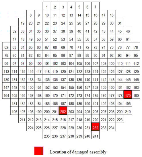
Figure 11.
Location of damaged fuel assembly.
It can be confirmed that the fuel assembly is damaged if the third minimum DNBR of 124 runs at location numbers of 179, 202, and 232 does not meet the acceptance criterion while the individual ranges of core inlet flows are applied. Figure 12 shows the third minimum DNBR of 124 runs in the individual flow range, and it is observed that all cases do not meet the acceptance criterion.
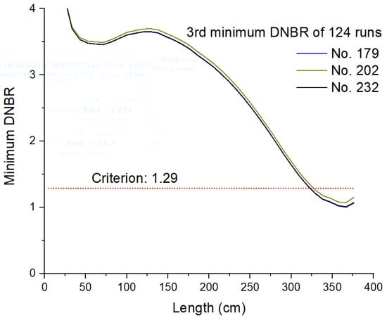
Figure 12.
The results of the third minimum DNBR on the three fuel assemblies.
When converted to the number of fuel rods, 769 rods account for 1.24% of the total rods. This result clearly represented that the number of damaged fuel rods was less than that of the FSAR results, which was 7% of the total rods. For these quantitative results, the possibility of slight variation in accordance with the sampling method and technique should be noted.
4. Conclusions
This study was a new attempt to evaluate the departure from nucleate boiling ratio (DNBR) with realistic simulations of a core flow distribution in a single seized reactor coolant pump (RCP) accident. The conclusions of this study can be summarized as follows:
- (1)
- In contrast with assumptions made in the conventional accident analysis, this study reproduced the physical behavior of all four RCPs and evaluated the flow rate of reversing the core in the affected loop.
- (2)
- In order to obtain the uncertainty range on the core inlet flow at the reactor lower plenum, the advanced power reactor 1400 (APR 1400) geometry was reproduced realistically with computational fluid dynamics (CFD).
- (3)
- A sub-channel analysis considering the entire fuel assemblies was carried out, and a quantitative result for the DNBR at 95/95 was obtained from 124 runs of sub-channel code considering the uncertainty of the core inlet flow.
- (4)
- An optimized evaluation methodology of a non-loss of coolant accident (non-LOCA) was implemented from the perspective of uncertainty on the core inlet flow by inter-linking the system behavior, a three-dimensional thermal-hydraulic analysis, and the precise sub-channel code and uncertainty tool.
Author Contributions
Conceptualization, I.S.L.; methodology, I.S.L., D.H.Y., and T.H.K.; writing—original draft preparation, I.S.L.; writing—review and editing, Y.S.B. and Y.C.K.; supervision, I.S.L. and Y.C.K. All authors have read and agreed to the published version of the manuscript.
Funding
The Nuclear Safety Research Program through the Korea Foundation of Nuclear Safety (KOFONS) and the Nuclear Safety and Security Commission (NSSC), Republic of Korea grant number 1805004-0320-SB120.
Institutional Review Board Statement
Not applicable.
Informed Consent Statement
Not applicable.
Data Availability Statement
Not applicable.
Conflicts of Interest
The authors declare no conflict of interest.
References
- Wilson, G.E. Historical insights in the development of Best Estimate Plus Uncertainty safety analysis. Ann. Nucl. Energy 2013, 52, 2–9. [Google Scholar] [CrossRef]
- Zhang, J.; Kovtonyuk, A.; Schneidesch, C. Towards a graded application of best estimate plus uncertainty methodology for non-LOCA transient analysis. Nucl. Eng. Des. 2019, 354, 110189. [Google Scholar] [CrossRef]
- Cheng, Z.; Rao, Y.F. Strategies for developing subchannel capability in an advanced system thermal-hydraulic code: A literature review. AECL Nucl. Rev. 2014, 4, 23–41. [Google Scholar] [CrossRef]
- Korea Institute of Nuclear Safety. Evaluation of ECCS Performance for Large Break Loss of Coolant Accident of Shinkori Units 3&4; KINSL: Daejeon, Korea, 2008. [Google Scholar]
- Nuclear Regulatory Commission. Transient and Accident Analysis Methods, Regulatory Guide 1.203; USNRC: Washington DC, USA, 2005.
- Smith, B.L.; Song, C.H.; Chang, S.K.; Lee, J.R.; Kim, J.W. Report of the OECD/NEA KAERI Rod Bundle CFD Benchmark Exercise; OECD: Paris, France, 2013. [Google Scholar]
- Höhne, T. Numerical simulation of coolant mixing in a pressurized water reactor with different CFD methods based on complex meshes. Int. J. Nucl. Energy Sci. Tech. 2017, 3, 399–412. [Google Scholar] [CrossRef]
- Rohde, U. Application of CFD codes in nuclear reactor safety analyses. Sci. Tech. Nucl. Install. 2009, 2010, 1–8. [Google Scholar]
- Rohde, U.; Höhne, T.; Kliem, S.; Hemström, B.; Scheuerer, M.; Toppila, T.; Aszodi, A.; Boros, I.; Farkas, I.; Mühlbauer, P.; et al. Fluid mixing and flow distribution in a primary circuit of a nuclear pressurized water reactor—Validation of CFD codes. Nucl. Eng. Des. 2007, 237, 1639–1655. [Google Scholar] [CrossRef]
- Tian, Z.; Yang, L.; Han, S.; Yuan, X.; Lu, H.; Li, S.; Liu, L. Numerical Investigation on the Flow Characteristics in a 17 × 17 Full-Scale Fuel Assembly. Energies 2020, 13, 397. [Google Scholar] [CrossRef]
- Kim, K.M.; Lee, B.I.; Cho, H.H.; Park, J.S.; Chung, Y.-J. Numerical study on thermo-hydrodynamics in the reactor internals of SMART. Nucl. Eng. Des. 2011, 241, 2536–2543. [Google Scholar] [CrossRef]
- Bae, Y.; Kim, Y.I.; Park, C.T. CFD analysis of flow distribution at the core inlet of SMART. Nucl. Eng. Des. 2013, 258, 19–25. [Google Scholar] [CrossRef]
- Jeong, J.H.; Han, B.S. Coolant flow field in a real geometry of PWR downcomer and lower plenum. Ann. Nucl. Energy 2008, 35, 610–619. [Google Scholar] [CrossRef]
- Sun, L.; Peng, M.; Xia, G.; Lv, X.; Li, R. Numerical Study on Coolant Flow Distribution at the Core Inlet for an Integral Pressurized Water Reactor. Nucl. Eng. Technol. 2017, 49, 71–81. [Google Scholar] [CrossRef][Green Version]
- Zhang, K. The multiscale thermal-hydraulic simulation for nuclear reactors: A classification of the coupling approaches and a review of the coupled codes. Int. J. Energy Res. 2020, 44, 3295–3315. [Google Scholar] [CrossRef]
- Wang, C.; Cao, L.; Zhang, X.; Shen, C.; Chen, H. Development and application of CFD and subchannel coupling analysis code for lead-cooled fast reactor. Int. J. Energy Res. 2019, 43, 8447–8462. [Google Scholar] [CrossRef]
- Yoon, S.J.; Kim, S.B.; Park, G.C.; Yoon, H.Y.; Cho, H.K. Application of CUPID for subchannel-scale thermal–hydraulic analysis of pressurized water reactor core under single-phase conditions. Nucl. Eng. Technol. 2018, 50, 54–67. [Google Scholar] [CrossRef]
- Korea Institute of Nuclear Safety. MARS-KS Code Manual; KINS: Daejeon, Korea, 2015. [Google Scholar]
- Wilks, S.S. Determination of Sample Sizes for Setting Tolerance Limits. Ann. Math. Stat. 1941, 12, 91–96. [Google Scholar] [CrossRef]
- Heo, J.; Kim, K.D. PAPIRUS, a parallel computing framework for sensitivity analysis, uncertainty propagation, and estimation of parameter distribution. Nucl. Eng. Des. 2015, 292, 237–247. [Google Scholar] [CrossRef]
- Lemaire, M. Chapter 2: Modelling Uncertainty. Mechanics and Uncertainty; Wiley: Hoboken, NJ, USA, 2014. [Google Scholar]
- Lee, I.S. Regulatory Audit Assessment of Non-LOCA (MSLB and LR) on the Fuel Damage for APR1400; KINS: Daejeon, Korea, 2019. [Google Scholar]
- Lee, I.S. Development of Regulatory Audit Methodology and Criteria on Core Coolability for Design Basis Accidents; KINS: Daejeon, Korea, 2019. [Google Scholar]
- Ansys Inc. ANSYS CFX-19 Manual; Ansys Inc.: Canonsburg, PA, USA, 2018. [Google Scholar]
- Avramova, M. Development of an Innovative Spacer Grid Model utilizing Computational Fluid Dynamics within a Subchannel Analysis Tool. Ph.D. Thesis, Pennsylvania State University, Malvern, PA, USA, 2007. [Google Scholar]
- Blyth, T. Improvement of COBRA-TF Subchannel Thermal-Hydraulics Code (CTF) Using Computational Fluid Dynamics; Pennsylvania State University: Malvern, PA, USA, 2014. [Google Scholar]
- Salko, R.; Avramova, M. COBRA-TF Subchannel Thermal-Hydraulic Code (CTF) Theory Manual; Pennsylvania State University: Malvern, PA, USA, 2015. [Google Scholar]
- KEPCO Nuclear Fuel. PLUS7 Fuel Design and Safety Evaluation for Korean Standard Nuclear Power Plants; KEPCO Nuclear Fuel: Daejeon, Korea, 2006. [Google Scholar]
- Lee, G.H. Numerical Analysis of Flow Distribution inside a Fuel Assembly with Split-Type Mixing Vanes for the Development of CFD Best Practice Guideline; KINS: Daejeon, Korea, 2017. [Google Scholar]
- Takemoto, M.; Sakai, S.; Wakai, K.; Sumida, I.; Kondou, T.; Inatomi, T. Investigation of two-phase flow mixing between two subchannels. Heat Transf.-Asian Res. 2000, 29, 412–426. [Google Scholar] [CrossRef]
Publisher’s Note: MDPI stays neutral with regard to jurisdictional claims in published maps and institutional affiliations. |
© 2021 by the authors. Licensee MDPI, Basel, Switzerland. This article is an open access article distributed under the terms and conditions of the Creative Commons Attribution (CC BY) license (http://creativecommons.org/licenses/by/4.0/).