1. Introduction
The increasing use of modern devices has increased the energy crisis to meet the energy demands of the world’s growing population [
1,
2,
3,
4,
5]. Modern power systems integrated with information and communication technology (ICT) add flexibility for consumers but more challenges for stockholders due to their operation and control [
6,
7,
8]. The reliable operation of modern power systems depends on many factors, such as accurate system modeling, control, disturbance-handling capabilities, and so forth [
9,
10,
11,
12].
Interconnected power systems (INPSs) consist of several subgeneration units or areas that can operate individually. Each area of an INPS has separate generation units connected by a tie line. The function of this line is to manage the flow of power between the areas [
13,
14,
15].
Maintaining the tie-line power at its nominal value is a challenge and requires a great deal of attention [
16,
17,
18,
19]. Frequency deviation due to improper matching between the generation and demand may result in the loss of harmony and a complete blackout. Frequency deviation and tie-line power mismatch may introduce load damage, a reduction in production, overheating, and so on [
12,
20,
21].
Experts have reported several methods to compensate for the frequency deviation of INPSs [
17,
22,
23,
24,
25,
26]. These methods mitigate deviation against the uncertainty, disturbance, and nonlinear behavior of the system but not against a cyberattack (CA). The mitigation of a CA on power systems has brought a new research dimension for researchers. If the CA is realistic, the malefactors can easily provide false data through the communication link to the power system control station. The injection of false data may increase the possibility of unrealistic system performance [
27,
28,
29,
30].
The rate of CAs on cyberphysical systems (CPSs) has increased significantly over the last decade. Recent news has attracted the attention of the researchers to develop strong security for CPSs. The CA on the U.S. gas pipeline and smart grid, as well as on the Ukraine power system, indicates the frequent and regular occurrence of attacks on power systems [
31,
32,
33]. Grid reliability and resiliency were largely affected by this CA. Unauthorized access, false data injection, data integrity, sensitive data collection, etc., are some of the objectives of attackers to hamper power systems [
34,
35,
36].
Although several load frequency controllers (LFCs) are designed to minimize frequency deviation, they may also be largely affected by CAs. The function of LFCs is to collect data from the frequency sensor and regulate the speed of the generation units. Any changes in the speed regulator by the governor make the governor’s speed uncontrollable and produce a large frequency as well as a tie-line power deviation of the INPS. Again, any changes in the associated control parameters are also responsible for reducing the stability margin and reliability of the system. Thus, the speed regulator and control variables are critical parameters that attract the attackers’ attention [
37,
38,
39].
Conventional control methods can only control the system performance against system dynamics and different disturbances. The control of a CA is rarely possible with the help of these control methods. The parameters of the system and the controller are sensitive data that can easily be modified by attackers. Thus, alone, the controller cannot assure the stability of the system during a CA, which ensures the requirement of a cybersecurity-based control algorithm [
40].
A CA on the parameters and settings of the system can be mitigated by analyzing the behavior of the circuit breaker, protection devices, and logics [
41]. The detection of false data injection based on the measurement variation method is proposed in [
42]. The control algorithm detects the presence of a CA by measuring the distances between two probability distributions. Reference [
43] proposes a transformation-based scheme used to find the modification or injection of false data into the smart grid. The investigation of a CA is carried out by proper estimation of the measurement variation based on the Kullback–Leibler distance algorithm. The power system has a quasistatic nature that reduces the detection capability of this method.
Reference [
38] considers a technique to provide false data to the power system and investigates its impact on production costs and demands. Positively and negatively biased CAs and their impacts on the power system are discussed in [
40]. This work proposes a switching technique to control a LFC with an integrator controller. Another switching algorithm is investigated in [
44]. The authors of [
45] analyzed the frequency deviation of a single-area power system with a LFC and an automatic generation control (AGC) against positively and negatively biased CAs. The positively biased CA produced a greater impact on both the LFC and AGC compared to the negatively biased CA.
The aforementioned research articles provide control structures against CAs for a single-area power system, although they are unable to protect the operation of the INPS during a CA. Although the integrator-based AGC confirms the reliable operation for a single-unit LFC, the use of INPSs can be questionable due to their multiple control parameters, and these controllers are also sensitive to change in operating conditions. Therefore, a separate protection unit for INPS must be considered during a CA. Inspired by the above issues, this work proposes a novel security unit, called the automatic intrusion mitigation unit (AIMU), to protect INPSs during a CA. The contributions of this article are:
The design of a fractional-order PID (FPID) controller to compensate for frequency deviation and the tie-line power mismatch of an interconnected power system.
The investigation of the closed-loop interconnected power system’s behavior due to changes in sensitive parameters such as the speed regulator, biasing factor, and parameters of the controller.
The design of a novel security unit for the INPS to mitigate the frequency deviation and tie-line power discrepancy against the parameter changes of both the system and controller due to a CA.
This paper is organized as follows.
Section 2 models the INPS, and
Section 3 discusses the load frequency controller design. The impacts of a CA, the proposed switching technique, and the performance of the AIMU are investigated in
Section 4,
Section 5 and
Section 6. The conclusions are presented in
Section 7.
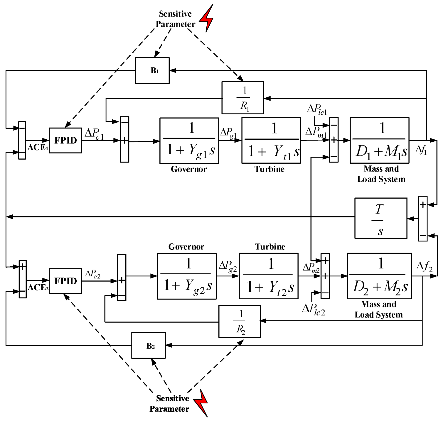
2. Interconnected Power System Modeling
The control structure of the INPS is constructed by using two control loops; e.g., the primary and secondary loops for controlling frequency. The primary loop acts as a proportional loop that decreases the frequency deviation produced due to load and demand change, but it is unable to regain zero frequency deviation. The frequency deviation returns to a nominal value (i.e., zero deviation) by implementing another control loop, known as the secondary frequency control loop.
Figure 1 presents a model of an INPS that has three main components: a governor, a turbine, and a mass-load system. The mass-load system produces an impact on the INPS, the model of which can be represented by [
12,
14,
16,
46,
47]
where
M and
D are the inertia and damping constant. The governor can be modeled as
The performance of the governor largely depends on the parameter known as the speed regulator (R). Any variation of this parameter is responsible for deviating the speed of the generation unit and increasing the frequency and power deviation. Another element known as the turbine can be modeled as
For an INPS, two or more areas are connected to each other and deliver power through the tie line, the model of which can be represented by
where
is the reluctance of the tie line and areas. The load change is usually kept small; e.g., 2%. Thus, the delivered tie-line power due to the small perturbation of load where
can be represented by
The reference signal and feedback construct the area control error (
ACE) that feeds the error measurement to the controller to minimize the frequency and power deviation. The model of
ACE can be given as
where
B is a biasing factor that can be represented by
In an INPS, there are nine total state variables. There are three state variables for each area; i.e.,
,
,
, and
,
, and
. There is one state variable for the tie line; i.e.,
. Finally, there are two state variables for the inputs
and
. Thus, the dynamic model of the INPS can be represented by
Thus, the INPS in the form of state space can be written as
Table 1 lists the values of the parameters of the INPS.
3. Load Frequency Controller Design
In an INPS, the frequency and ACE are two crucial pieces of data that need to be controlled to increase the level of protection of the power system. Any change in the supply-to-demand ratio or the speed regulator of the governor is responsible for deviations from the nominal frequency. A frequency controller is implemented to control these frequency deviations in the power system with an additional control approach. In this work, we designed a FPID controller for load frequency control.
The
FPID controller is a modified conventional integer-order
PID controller based on the fractional calculus used to design the integral and derivative mode of the
FPID controller [
48,
49,
50]. Thus, the construction of the
FPID controller provides two more controlling parameters that enhance the tuning performance of the
FPID controller.
The dynamic model of an integral part of the
FPID controller can be written as
Here, is the function of the FI controller having fractional order .
Similarly, the derivative part of this controller can be defined as
From the above two equations, the output of the
FPID controller can be given as
Thus, the
FPID controller in the frequency domain can be represented by
where
a and
b are the power of the I and D of the
FPID controller. The
FPID controller has five modes of operation:
- (i)
The FPID acts as a FPID controller when a is a fractional number and b is a fractional number;
- (ii)
The FPID acts as a P controller when a = 0 and b = 0;
- (iii)
The FPID acts as a PI controller when a = 1 and b = 0;
- (iv)
The FPID acts as a PD controller when a = 0 and b = 1;
- (v)
The FPID acts as a PID controller when a = 1 and b = 1.
a and
b of the
FPID controller enhance the system quality and performance compared to the
PID and
PI controllers in the case of a smaller processing time and larger bandwidth, as well as being suitable for higher-order systems [
51,
52,
53]. In this work, we selected
a1 = 0.995,
b1 = 1.5 and
a2 = 2,
b2 = 1.5 to design the
FPID controller and compared the results with those of the integer-order
PI and
PID controllers, considering
a = 1,
b = 0 and
a = 1,
b = 1, respectively.
The high performance of the
FPID controller compared to the
PI and
PID controllers can be investigated from
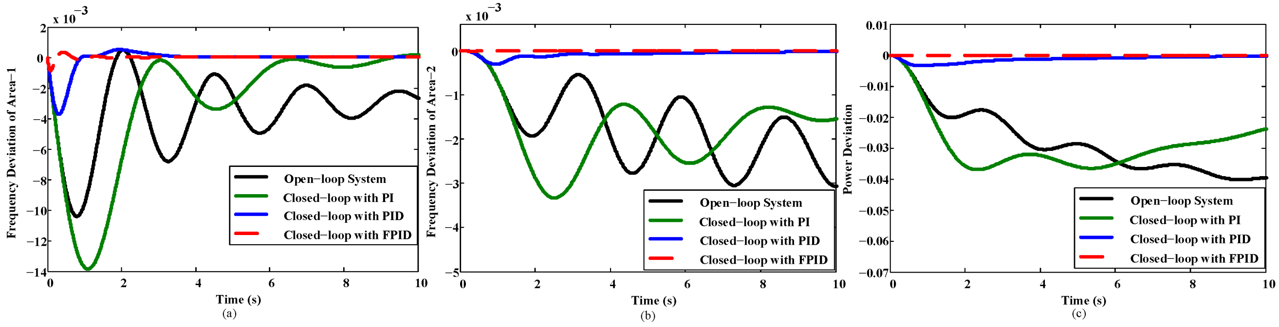
Figure 2. As presented in
Figure 2, the studied open-loop system indicates a high level of oscillation against a step input and deviates by a large frequency and tie-line power from the reference, whereas the
FPID controller has approximately zero deviation of frequency and tie-line power from the reference, which is the lowest compared to the integer-order
PI and
PID controllers.
4. Effects of a Cyberattack
The design of the LFCs only for the INPS is not enough to guarantee protection against a CA. This is because the control parameters can also be targeted by attackers.
Figure 2 shows that although the system is efficiently controlled by implementing different control approaches, any change in the controller or system parameters may lead to deviation from the nominal operation of the system. This work aimed to address the causes of parameter changes and present a solution to overcome these problems. Misleading information about the frequency measurement, speed regulator, or controller parameters due to a CA are responsible for generating false
ACE signals, and the power system may produce or supply an undesirable amount of power. Thus, system frequency, as well as the power of the system, will be greatly affected [
28].
The adverse effect on the INPS due to a parameter variation was investigated. The variation of sensitive parameters, such as the speed regulator, the biasing factor of the system, and , , , a, and b of the FPID, PID, and PI controllers is considered. This case study is essential to address the need for INPS security and mitigate the effects of the unwanted changing of the parameters.
4.1. Case Study 1: Variation of the Speed Regulator
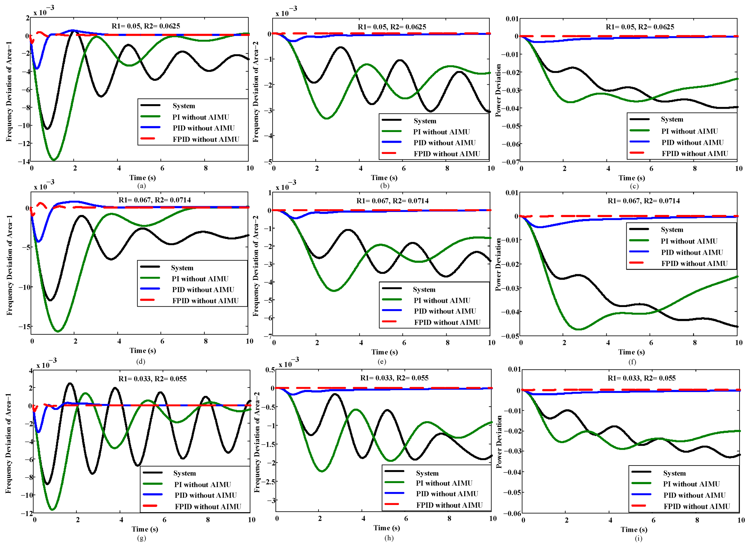
The speed regulator (R) is a sensitive parameter. The change of
R produces an impact on the speed of the governor responsible for deviating the system frequency and power.
Figure 3 shows that any small change of
R is responsible for deviating the performance of the INPS and making the system operation unreliable.
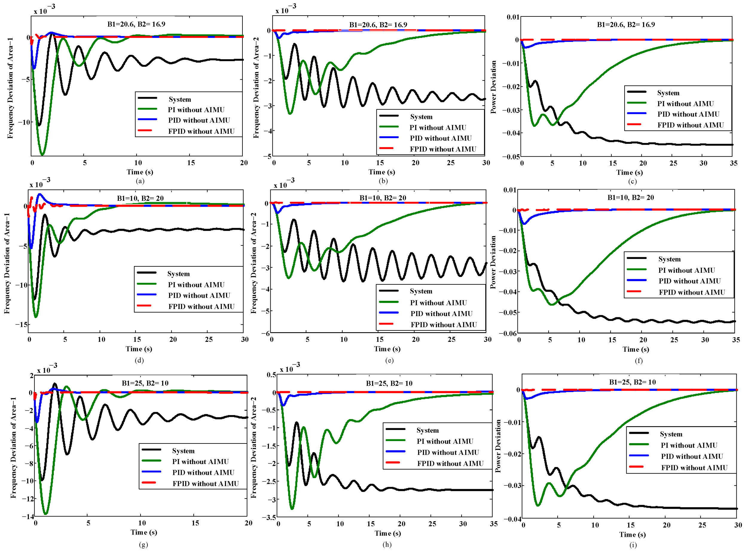
4.2. Case Study 2: Variation of the Biasing Factor
The biasing factor (B) is another critical parameter that produces an impact on the construction of the
ACE signal. The change of
B1 and
B2 is responsible for producing the wrong error signal fed to the controller. Thus, a wrong control signal is produced by the associated controller and may increase fluctuations in the INPS performance. The impact due to the change of
B is shown in
Figure 4.
Figure 4 shows a huge change in the performance of the INPS due to the variable value of
B that may cause the system to become unstable and damage the load.
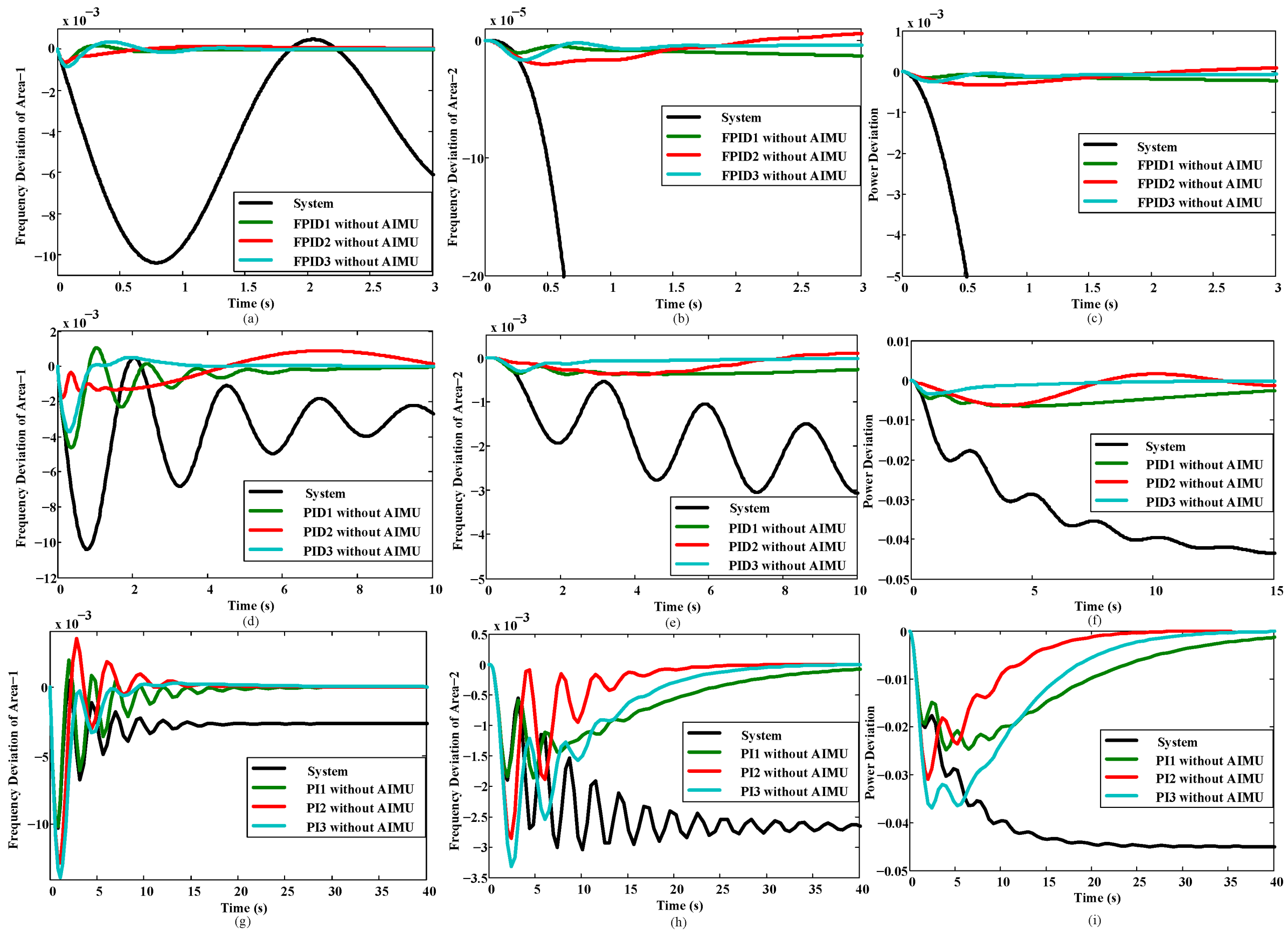
4.3. Case Study 3: Variation of the Controller Parameter
The performance of the INPS largely depends on the efficient design of the controller. The stable and reliable operation of the whole system and loads is directly related to the control efficiency and structure. Any change of this control structure will make the controller unable to produce the required control signals.
Table 2 was used to test the controller performance without an AIMU.
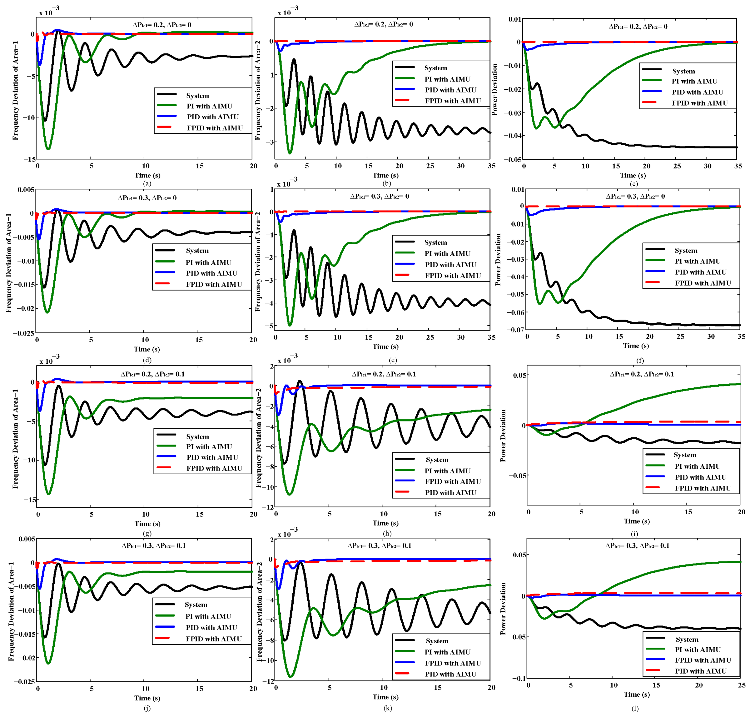
Figure 5 presents the variation of the controller parameters and their impacts on the deviation of area frequency and power.
Table 3 presents the impacts of the parameter changes on the power system.
The findings of these case studies present the evidence of the lack of system security in conventional power systems. Any change of the sensitive parameters is responsible for deviating system performance, as shown in
Figure 3 and
Figure 4. Researchers are always interested in developing different control algorithms to control system performance against any disturbance, uncertainties, or system dynamics.
PI,
PID,
FPID, or other control algorithms are inventions of researchers to control system stability under system parameter variation or disturbance.
Today’s research not only focuses on the design of any controller but also accounts for the security issue because it is rarely possible to control modern devices with a single controller due to the development of ICT. At present, ICT makes it possible to easily access any modern system. Controllers such as
PI,
PID, or
FPID are able to control system performance but are unable to ensure the cybersecurity of the system. Thus, choosing only the controller without considering a CA hampers both the system and controller parameters because attackers can attack both the system and controller, as shown in
Figure 3,
Figure 4 and
Figure 5. To address these issues, it is essential to design a cybersecurity-based controller that not only stabilizes system performance but also diminishes the adverse effects of false data injection into both the system and controller.
5. Design Methodology of the Proposed Automatic Intrusion Mitigation Unit
It is obvious from the aforementioned discussion that the biasing factor and speed regulator of the governor, as well as the variables of the associated control unit of the INPS, are attracting parameters to attackers. By changing these parameters through the CA, they can destroy the power system and interrupt the delivery of power to the customer.
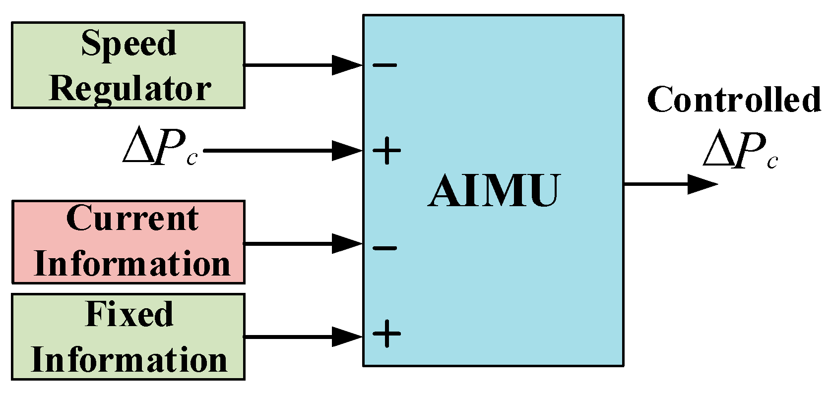
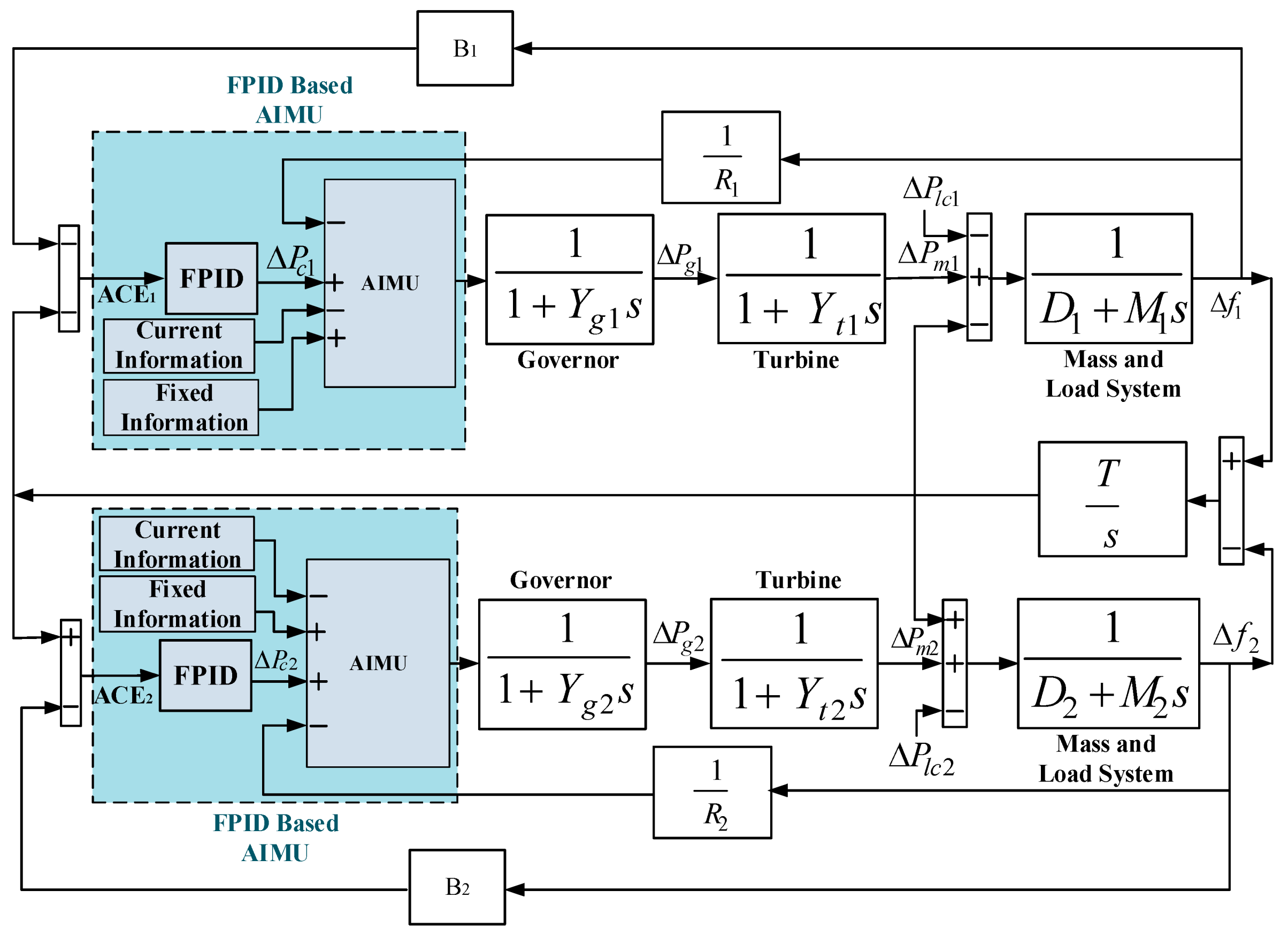
In this paper, an automatic intrusion mitigation unit (AIMU), as shown in
Figure 6, is proposed that mitigates the effects of a CA and enhances the security of the INPS, the construction of which is shown in
Figure 7 and is the main contribution of this paper. This control technique has both a network and hardware connection. The control structure of the proposed AIMU has four input terminals that account for the speed regulator, control signal from the
FPID controller, current, and fixed information of the sensitive data collected from the network and hardware. The fixed data stored in the AIMU are termed hardware data. The data information of the system may change against the system dynamics, uncertainties, and disturbance, as well as the CA. Thus, the present data information of the system and controller at every moment is considered networked data.
The detection of the current information about sensitive data is important to identify the presence of a CA. The collection of information from both the hardware and network is essential to maintain the safe and reliable operation of a power system. To regulate the balance between supply and demand, the service provider manually modifies hardware data such as the parameters and setup of the system and controller. Once the data are modified, the service provider will make the data fixed to overcome illegal data modification or injection.
The data of a nominal system and the parameter values of a controller at which it provides better performance are considered fixed data. The fixed data for both the system and controller are listed in
Table 1 and
Table 4. The speed regulator and biasing factor of the INPS, as well as
,
,
,
a, and
b of the
FPID,
PID, and
PI controllers, are sensitive parameters usually affected by a CA. Thus, it is necessary to protect these parameters from attackers. To secure these parameters from attackers, hardware with an offline connection can be used to store the data, which acts as an input to the AIMU. The AIMU can only read data from this hardware for its further comparison process. This control unit cannot write or update these fixed hardware data without the permission of the service providers. This way, the proposed AIMU prevents the unauthorized access of attackers to the fixed data.
The AIMU then continuously monitors the present situation of these sensitive networked data of the INPS, and the controller and compares these networked data with the fixed hardware data at every moment to calculate the difference between the monitored data and fixed data.
The AIMU acts as a control unit that performs a mathematical calculation between the hardware and networked data. The polarity of the four input terminals such as R, , the fixed, and the current information of the AIMU is selected in such a way that all the monitored network data such as R, , and the current information are subtracted from the fixed hardware data to find any change between them, and their algebraic summation always generates the required constant value of the parameters for the system and controller. If it finds no changes between the measured data and the fixed data, it ensures the absence of a CA on the system. If any changes of these parameters are noticed by the AIMU, it generates a control signal to indicate the presence of a CA on the system or controller, makes the algebraic summation of R, , and the current information equal zero, and allows the fixed hardware data to control the system. Thus, any change of the data can be overcome automatically, and the system always exhibits a fixed performance with the aid of the AIMU, which protects the system against the diverse effects of an unauthorized CA.
Thus, the AIMU is designed considering its hardware is protected from a cyberattack due to its fixed offline operation. This means attackers can only attack the network data, which may change the system or controller parameters. The proposed AIMU detects changes in the network data, minimizes the effects on the system performance due to the parameter variations, and reduces the error to zero, based on the fixed hardware data.
6. Performance Evaluation
The performances of the INPS with and without the implementation of the AIMU are inspected here. The open-loop performance of the INPS, as shown in
Figure 2, demonstrates the necessity for the controller design to make the system stable and reduce the oscillations in the INPS performance. For the stable operation of the INPS, a
FPID controller is designed in this paper, which is further compared with conventional
PI and
PID controllers. To understand the impact of a CA on the INPS, a mimic environment of a CA is created, and the performance of the INPS is inspected in
Figure 3,
Figure 4 and
Figure 5. For further improvement, the performance of the controller-based AIMU is investigated under load and wind power change.
6.1. Performance Analysis with the AIMU
The parameter variations and their effects were inspected in Case Studies 1–3, which are presented in
Figure 3,
Figure 4 and
Figure 5, and their impacts are listed in
Table 3. These ensure the necessity for the implementation of the AIMU to protect the system from CA and confirm the constant behavior of the INPS.
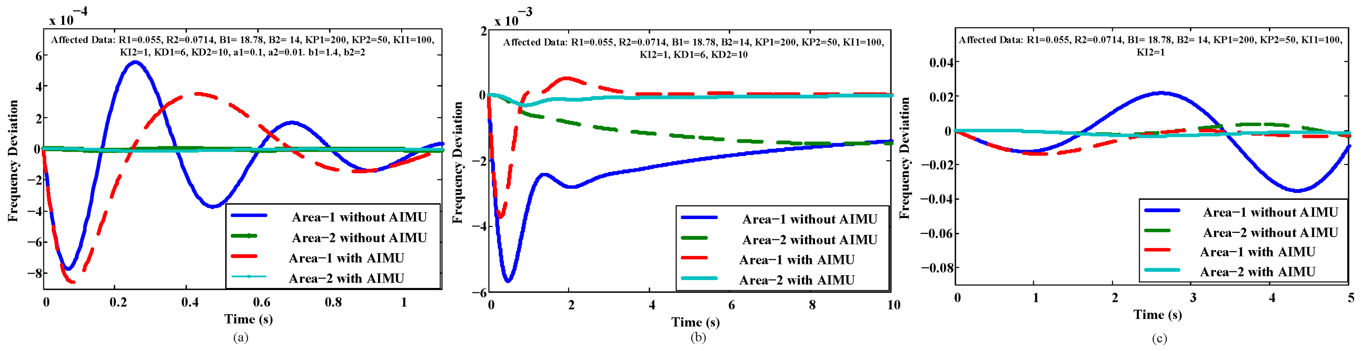
To evaluate the reliable and fixed behavior of the AIMU,
Table 4 is used to list some affected and fixed data of the speed regulator and controller parameters. The affected data of
Table 4 are used to produce a mimic environment of a CA to evaluate the effectiveness of the proposed AIMU. With these affected data, the performance of the INPS deviates from its fixed operation, which may damage the system and load.
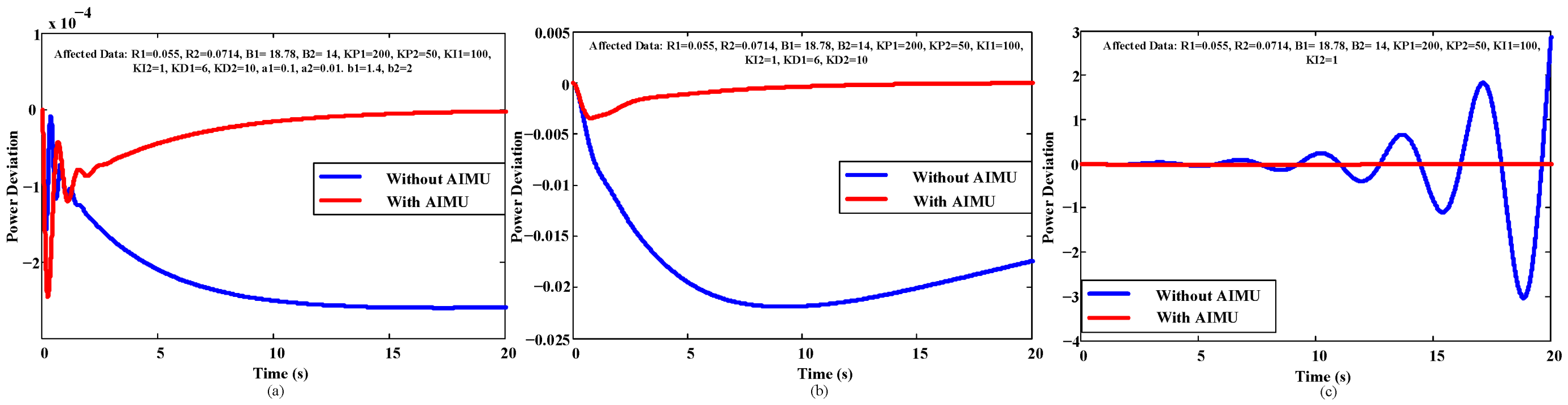
Figure 8 and
Figure 9 show the performance of the affected and secured systems. The implementation of the AIMU completely eliminates the affected data from the power system and feeds the fixed data from the hardware to exhibit constant frequency and power deviation control similar to the responses before a cyberattack. Thus,
Figure 8 and
Figure 9 ensure the robust performance of the INPS with any changes of the system and control unit.
Table 5 shows the performance of the different control algorithms with the AIMU.
6.2. Performance Evaluation under Load Change
The load change connected to the INPS is also responsible for diverging the performance of the INPS. The effects due to the change of in the power system need to be controlled efficiently to maintain favorable INPS behavior.
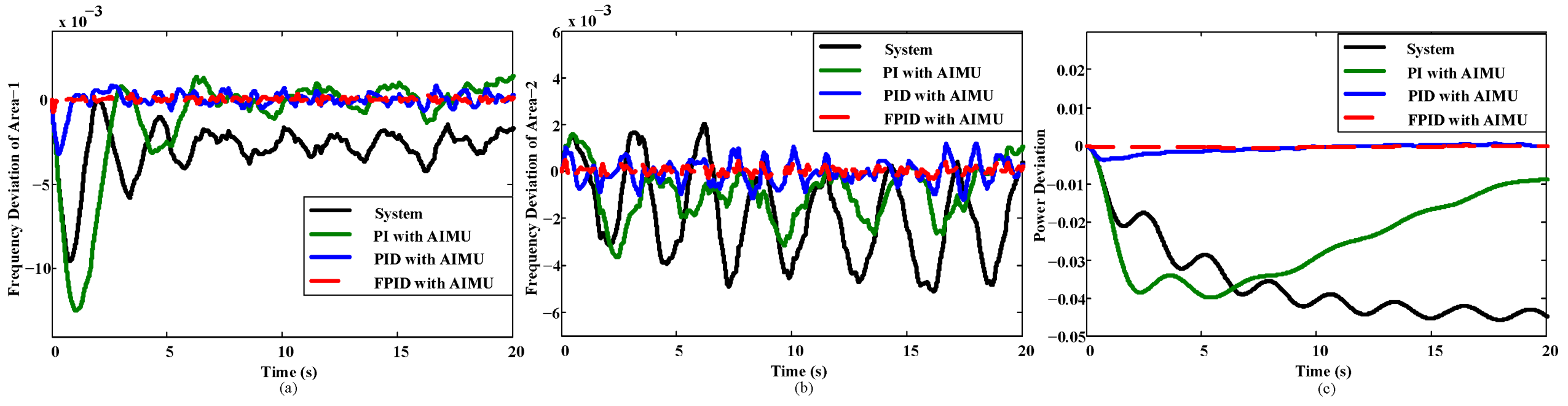
The performance of the INPS in the case of load change is presented in
Figure 10, exhibiting a huge deviation of INPS performance due to the load variation. The
FPID controller efficiently minimizes the frequency and power deviation compared to the
PI and
PID controllers.
Table 6 ensures the better performance of the
FPID controller with AIMU with respect to rise time (RT), settling time (ST), and overshoot (OS).
6.3. Performance Evaluation under Wind Power Change
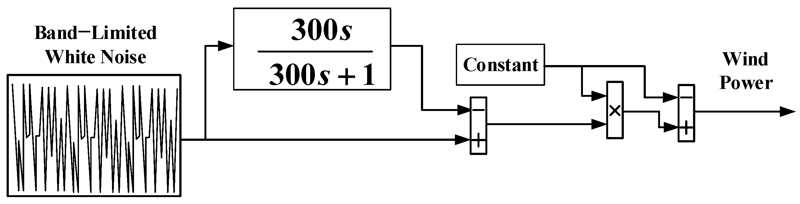
The performance of the INPS in this paper is also investigated under the presence of a renewable energy source. As a renewable energy source, wind energy is considered here. The variation of wind power, as presented in
Figure 11, provides an inconsiderable impact on the frequency and power deviation and makes the system unstable [
54].
Figure 12 presents the performance of the power system in the case of a wind power variation. The better performance of the
FPID controller in the presence of the wind power variation makes it a high-performance control approach for INPS.
7. Conclusions
The cybersecurity of modern power systems is crucial to empower their reliability, stability, and resilience. The dissimilarity of any element out of the reference increases the possibility of partially or completely damaging a power grid. In this paper, we proposed a novel intrusion mitigation unit to diminish the modification of all critical elements during the cyberattack of an interconnected power system. A two-area interconnected power system is modeled and stabilized by designing a
FPID controller to compensate for frequency deviation and tie-line power mismatch. The closed-loop performance of the designed
FPID controller over the conventional integer-order
PI and
PID controller remains superior in managing frequency deviation and tie-line power against no cyberattack. On the other hand, the
FPID controller has no control over a cyberattack and executes undesirable performance. To limit and compensate for the effect of a cyberattack, the proposed security unit was designed using the status of the
FPID controller and others. The effectiveness of the proposed AIMU is tested and compared with that of the
PI and
PID controller against a cyberattack, load variations, and the incorporation of noises. The proposed AIMU diminishes the diverse effects of a CA and efficiently minimizes the effect of load change and noise, the importance of which are listed in
Table 7. The design of the proposed AIMU by AI techniques will be investigated further in the future.
Author Contributions
Conceptualization, F.R.B. and S.K.S.; methodology, F.R.B., S.K.S. and S.R.F.; formal analysis, F.R.B., Z.N. and D.D.; investigation, F.R.B., S.K.S., S.K.D. and S.M.M.; writing—original draft preparation, F.R.B. and S.K.D.; writing—review and editing, F.R.B., S.K.S., S.K.D., S.M.M. and M.R.I.S.; supervision, S.K.D., S.M.M. and M.R.I.S. All authors have read and agreed to the published version of the manuscript.
Funding
This research received no external funding.
Institutional Review Board Statement
Not applicable.
Informed Consent Statement
Not applicable.
Data Availability Statement
Not applicable.
Conflicts of Interest
The authors declare no conflict of interest.
References
- Gurrala, G.; Sen, I. Power System Stabilizers Design for Interconnected Power Systems. IEEE Trans. Power Syst. 2010, 25, 1042–1051. [Google Scholar] [CrossRef]
- Sarkar, S.K.; Badal, F.R.; Das, S.K. A comparative study of high performance robust PID controller for grid voltage control of islanded microgrid. Int. J. Dyn. Control. 2017, 6, 1207–1217. [Google Scholar] [CrossRef]
- Guha, D.; Roy, P.K.; Banerjee, S. Load frequency control of interconnected power system using grey wolf optimization. Swarm Evol. Comput. 2016, 27, 97–115. [Google Scholar] [CrossRef]
- Sarker, S.K.; Badal, F.R.; Das, P.; Das, S.K. Multivariable integral linear quadratic Gaussian robust control of islanded microgrid to mitigate voltage oscillation for improving transient response. Asian J. Control. 2019, 21, 2114–2125. [Google Scholar] [CrossRef]
- Badal, F.R.; Das, P.; Sarker, S.K.; Das, S.K. A survey on control issues in renewable energy integration and microgrid. Prot. Control. Mod. Power Syst. 2019, 4, 8. [Google Scholar] [CrossRef] [Green Version]
- Armin, M.; Rahman, M.; Rahman, M.; Sarker, S.K.; Das, S.K.; Islam, R.; Kouzani, A.Z.; Mahmud, M.A.P. Robust Extended H∞ Control Strategy Using Linear Matrix Inequality Approach for Islanded Microgrid. IEEE Access 2020, 8, 135883–135896. [Google Scholar] [CrossRef]
- Sarkar, S.K.; Badal, F.R.; Das, S.K.; Miao, Y. Discrete time model predictive controller design for voltage control of an islanded microgrid. In Proceedings of the 2017 3rd International Conference on Electrical Information and Communication Technology (EICT), Piscataway, NJ, USA, 7–9 December 2017; pp. 1–6. [Google Scholar]
- Mohanty, P.K.; Sahu, B.K.; Pati, T.K.; Panda, S.; Kar, S.K. Design and analysis of fuzzy PID controller with derivative filter for AGC in multi-area interconnected power system. IET Gener. Transm. Distrib. 2016, 10, 3764–3776. [Google Scholar] [CrossRef]
- Kiran, D.; Amani, G. Load Frequency Control of a Two-Area Power System Using FOPID with Harmony Search Algorithm. Int. J. Adv. Eng. Res. Sci. 2017, 6495, 12–17. [Google Scholar]
- Badal, F.R.; Subrata, K.S.; Sajal, K.D. Transient Stabilization Improvement of Induction Generator Based Power System using Robust Integral Linear Quadratic Gaussian Approach. Int. J. Smart Grid-ijSmartGrid 2019, 3, 73–83. [Google Scholar]
- Tasneem, Z.; Al Noman, A.; Das, S.K.; Saha, D.K.; Islam, R.; Ali, F.; Badal, F.R.; Ahamed, H.; Moyeen, S.I.; Alam, F. An analytical review on the evaluation of wind resource and wind turbine for urban application: Prospect and challenges. Dev. Built Environ. 2020, 4, 100033. [Google Scholar] [CrossRef]
- Ahmed, S.H.A. Load Frequency Control for a Two Area Power System. Ph.D. Thesis, University of Khartoum, Khartoum, Sudan, 2017. [Google Scholar]
- Pan, I.; Das, S. Fractional-order load-frequency control of interconnected power systems using chaotic multi-objective opti-mization. Appl. Soft Comput. 2015, 29, 328–344. [Google Scholar] [CrossRef] [Green Version]
- Chuang, N. Robust H-infinite load-frequency control in interconnected power systems. IET Control Theory Appl. 2016, 10, 67–75. [Google Scholar] [CrossRef]
- Thirukkovulur, A.K.; Nandagopal, H.; Parivallal, V. Decentralized control of multi-area power system restructuring for LFC optimization. In Proceedings of the 2012 IEEE International Conference on Computational Intelligence and Computing Research, Bengaluru, India, 16–19 December 2012; pp. 1–6. [Google Scholar]
- Shah, N.N.; Kotwal, C.D. The state space modeling of single two and three ALFC of power system using integral control and optimal LQR control method. IOSR J. Eng. 2012, 2, 501–510. [Google Scholar] [CrossRef]
- Farhangi, R.; Boroushaki, M.; Hosseini, S.H. Load–frequency control of interconnected power system using emotional learn-ing-based intelligent controller. Int. J. Electr. Power Energy Syst. 2012, 36, 76–83. [Google Scholar] [CrossRef]
- Shabani, H.; Vahidi, B.; Ebrahimpour, M. A robust PID controller based on imperialist competitive algorithm for load-frequency control of power systems. ISA Trans. 2013, 52, 88–95. [Google Scholar] [CrossRef] [PubMed]
- Fahim, S.R.; Yeahia, S.; Subrata, K.S.; Rafiqul, I.S.; Sajal, K.D. Self attention convolutional neural network with time series imaging based feature extraction for transmission line fault detection and classification. Electr. Power Syst. Res. 2020, 187, 106437. [Google Scholar] [CrossRef]
- Mu, C.; Tang, Y.; He, H. Improved Sliding Mode Design for Load Frequency Control of Power System Integrated an Adaptive Learning Strategy. IEEE Trans. Ind. Electron. 2017, 64, 6742–6751. [Google Scholar] [CrossRef]
- Saxena, S.; Hote, Y.V. Load Frequency Control in Power Systems via Internal Model Control Scheme and Model-Order Reduction. IEEE Trans. Power Syst. 2013, 28, 2749–2757. [Google Scholar] [CrossRef]
- Shayeghi, H.; Jalili, A.; Shayanfar, H. Multi-stage fuzzy load frequency control using PSO. Energy Convers. Manag. 2008, 49, 2570–2580. [Google Scholar] [CrossRef]
- Cam, E.; Gorel, G.; Mamur, H. Use of the Genetic Algorithm-Based Fuzzy Logic Controller for Load-Frequency Control in a Two Area Interconnected Power System. Appl. Sci. 2017, 7, 308. [Google Scholar] [CrossRef] [Green Version]
- Prakash, S.; Sinha, S. Simulation based neuro-fuzzy hybrid intelligent PI control approach in four-area load frequency control of interconnected power system. Appl. Soft Comput. 2014, 23, 152–164. [Google Scholar] [CrossRef]
- Giri, S.P.; Sinha, S.K. Four-Area Load Frequency Control of an Interconnected Power System Using Neuro-Fuzzy Hybrid Intelligent Proportional and Integral Control Approach. J. Intell. Syst. 2013, 22, 131–153. [Google Scholar] [CrossRef]
- Prakash, S.; Sinha, S. Application of artificial intelligence in load frequency control of interconnected power system. Int. J. Eng. Sci. Technol. 2011, 3, 3. [Google Scholar] [CrossRef]
- Teixeira, A.; Dan, G.; Sandberg, H.; Berthier, R.; Bobba, R.B.; Valdes, A. Security of smart distribution grids: Data integrity attacks on integrated volt/VAR control and countermeasures. In Proceedings of the 2014 American Control Conference, Portland, OR, USA, 4–6 June 2014; pp. 4372–4378. [Google Scholar]
- Tan, R.; Nguyen, H.H.; Foo, E.Y.S.; Yau, D.K.Y.; Kalbarczyk, Z.; Iyer, R.K.; Gooi, H.B. Modeling and Mitigating Impact of False Data Injection Attacks on Automatic Generation Control. IEEE Trans. Inf. Forensics Secur. 2017, 12, 1609–1624. [Google Scholar] [CrossRef]
- Esfahani, P.M.; Vrakopoulou, M.; Margellos, K.; Lygeros, J.; Andersson, G. Cyber-attack in a two-area power system: Impact identification using reachability. In Proceedings of the 2010 American Control Conference, Baltimore, MD, USA, 30 June–2 July 2010; pp. 962–967. [Google Scholar]
- Sridhar, S.; Manimaran, G. Data integrity attack and its impacts on voltage control loop in power grid. In Proceedings of the IEEE PES General Meeting, Detroit, MI, USA, 24–28 July 2011; pp. 1–6. [Google Scholar]
- Stuxnet Style Attack on US Smart Grid. 2018. Available online: https://www.scmagazineuk.com/stuxnet-style-attack-on-us-smart-gridcould-cost-government-1-trillion/article/535452/ (accessed on 12 January 2021).
- Ukraine’s Power Outage Was a Cyber Attack; Ukrenergo: Kyiv, Ucraina, 2017; Available online: http://www.reuters.com/article/.us-ukraine-cyber-attack-energyidUSKBN1521BA (accessed on 12 January 2021).
- US Gas Pipeline Hit by Cyber Attack. 2018. Available online: https://www.infosecurity-magazine.com/news/us-gas-pipelines-hit-by-cyberattack/ (accessed on 12 January 2021).
- Wadhawan, Y.; Almajali, A.; Neuman, C. A Comprehensive Analysis of Smart Grid Systems against Cyber-Physical Attacks. Electronics 2018, 7, 249. [Google Scholar] [CrossRef] [Green Version]
- Wood, P.; Bagchi, S.; Hussain, A. Defending against strategic adversaries in dynamic pricing markets for smart grids. In Proceedings of the 2016 8th International Conference on Communication Systems and Networks (COMSNETS), Bangalore, India, 5–10 January 2016; pp. 1–8. [Google Scholar]
- Wadhawan, Y.; Neuman, C.; Almajali, A. Analyzing cyber-physical attacks on smart grid systems. In Proceedings of the 2017 Workshop on Modeling and Simulation of Cyber-Physical Energy Systems (MSCPES), Pittsburgh, PA, USA, 21 April 2017; pp. 1–6. [Google Scholar] [CrossRef]
- Ten, C.W.; Manimaran, G.; Liu, C.C. Cybersecurity for critical infrastructures: Attack and defense modeling. In IEEE Transactions on Systems, Man, and Cybernetics-Part A: Systems and Humans; IEEE: Piscataway, NJ, USA, 2010; Volume 40, pp. 853–865. [Google Scholar]
- Deng, R.; Xiao, G.; Lu, R.; Liang, H.; Vasilakos, A.V. False data injection on state estimation in power systems—Attacks, im-pacts, and defense: A survey. IEEE Trans. Ind. Inf. 2016, 13, 411–423. [Google Scholar] [CrossRef]
- Ten, C.-W.; Liu, C.-C.; Manimaran, G. Vulnerability Assessment of Cybersecurity for SCADA Systems. IEEE Trans. Power Syst. 2008, 23, 1836–1846. [Google Scholar] [CrossRef]
- Hassan, M.; Roy, N.K.; Sahabuddin. Mitigation of frequency disturbance in power systems during cyber-attack. In Proceedings of the 2016 2nd International Conference on Electrical, Computer & Telecommunication Engineering (ICECTE), Rajshahi, Bangladesh, 8–10 December 2017; pp. 1–4.
- Liu, X.; Shahidehpour, M.; Li, Z.; Liu, X.; Cao, Y.; Li, Z. Power System Risk Assessment in Cyber Attacks Considering the Role of Protection Systems. IEEE Trans. Smart Grid. 2017, 8, 572–580. [Google Scholar] [CrossRef]
- Chaojun, G.; Jirutitijaroen, P.; Motani, M. Detecting False Data Injection Attacks in AC State Estimation. IEEE Trans. Smart Grid 2015, 6, 2476–2483. [Google Scholar] [CrossRef]
- Singh, S.K.; Khanna, K.; Bose, R.; Panigrahi, B.K.; Joshi, A. Joint-Transformation-Based Detection of False Data Injection Attacks in Smart Grid. IEEE Trans. Ind. Inform. 2017, 14, 89–97. [Google Scholar] [CrossRef]
- Yan, Y.; Qian, Y.; Sharif, H.; Tipper, D. A Survey on Cyber Security for Smart Grid Communications. IEEE Commun. Surv. Tutorials 2012, 14, 998–1010. [Google Scholar] [CrossRef] [Green Version]
- Sahabuddin; Dutta, B.; Hassan, M. Impact of cyber-attack on isolated power system. In Proceedings of the 2016 3rd International Conference on Electrical Engineering and Information Communication Technology (ICEEICT), Dhaka, Bangladesh, 22–24 September 2016; pp. 1–4. [Google Scholar]
- Mohamed, T.; Bevrani, H.; Hassan, A.; Hiyama, T. Decentralized model predictive based load frequency control in an inter-connected power system. Energy Convers. Manag. 2011, 52, 1208–1214. [Google Scholar] [CrossRef]
- Alhelou, H.H.; Golshan, M.E.H.; Fini, M.H. Wind Driven Optimization Algorithm Application to Load Frequency Control in Interconnected Power Systems Considering GRC and GDB Nonlinearities. Electr. Power Compon. Syst. 2018, 46, 1223–1238. [Google Scholar] [CrossRef]
- Shah, P.; Agashe, S. Review of fractional PID controller. Mechatronics 2016, 38, 29–41. [Google Scholar] [CrossRef]
- Li, C.; Zhang, N.; Lai, X.; Zhou, J.; Xu, Y. Design of a fractional-order PID controller for a pumped storage unit using a grav-itational search algorithm based on the Cauchy and Gaussian mutation. Inform. Sci. 2017, 396, 162–181. [Google Scholar] [CrossRef]
- Senberber, H.; Bagis, A. Fractional PID controller design for fractional order systems using ABC algorithm. In Proceedings of the 2017 Electronics, Palanga, Lithuania, 19–21 June 2017; pp. 1–7. [Google Scholar]
- Khezri, R.; Oshnoei, A.; Hagh, M.T.; Muyeen, S. Coordination of Heat Pumps, Electric Vehicles and AGC for Efficient LFC in a Smart Hybrid Power System via SCA-Based Optimized FOPID Controllers. Energies 2018, 11, 420. [Google Scholar] [CrossRef] [Green Version]
- Babaei, M.; Abazari, A.; Muyeen, S.M. Coordination between Demand Response Programming and Learning-based FOPID Controller for Alleviation of Frequency Excursion of Hybrid Microgrid. Energies 2020, 13, 442. [Google Scholar] [CrossRef] [Green Version]
- Ahmed, S.M.; Khalid, H.M.; Muyeen, S.M.; Al-Durra, A. A Prediction Algorithm to Enhance Grid Resilience Towards Cyber Attacks in WACS Applications. IEEE Syst. J. 2019, 13, 710–719. [Google Scholar]
- Li, X.; Hui, D.; Lai, X.; Yan, T. Power Quality Control in Wind/Fuel Cell/Battery/Hydrogen Electrolyzer Hybrid Micro-grid Power System. In Applications and Experiences of Quality Control; IntechOpen: London, UK, 2011. [Google Scholar] [CrossRef] [Green Version]
Figure 1.
Model of an interconnected power system.
Figure 1.
Model of an interconnected power system.
Figure 2.
Comparison of frequency deviations and tie-line power for open- and closed-loop systems. (a) Frequency deviation for Area 1; (b) frequency deviation for Area 2; (c) tie-line power.
Figure 2.
Comparison of frequency deviations and tie-line power for open- and closed-loop systems. (a) Frequency deviation for Area 1; (b) frequency deviation for Area 2; (c) tie-line power.
Figure 3.
Performance of the interconnected power system against the speed regulator variation without an automatic intrusion mitigation unit (AIMU).
Figure 3.
Performance of the interconnected power system against the speed regulator variation without an automatic intrusion mitigation unit (AIMU).
Figure 4.
Performance of the interconnected power system against the biasing factor variation without an AIMU.
Figure 4.
Performance of the interconnected power system against the biasing factor variation without an AIMU.
Figure 5.
Performance of the interconnected power system against the controller parameter variation without an AIMU.
Figure 5.
Performance of the interconnected power system against the controller parameter variation without an AIMU.
Figure 6.
Construction of an automatic intrusion mitigation unit.
Figure 6.
Construction of an automatic intrusion mitigation unit.
Figure 7.
Model of an AIMU-based INPS.
Figure 7.
Model of an AIMU-based INPS.
Figure 8.
Control of the frequency of the AIMU-based INPS with (a) FPID, (b) PID, and (c) PI controllers.
Figure 8.
Control of the frequency of the AIMU-based INPS with (a) FPID, (b) PID, and (c) PI controllers.
Figure 9.
Control of the tie-line power of the AIMU-based INPS with (a) FPID, (b) PID, and (c) PI controllers.
Figure 9.
Control of the tie-line power of the AIMU-based INPS with (a) FPID, (b) PID, and (c) PI controllers.
Figure 10.
Performance of the interconnected power system with PI, PID, and FPID controllers against load change with the AIMU.
Figure 10.
Performance of the interconnected power system with PI, PID, and FPID controllers against load change with the AIMU.
Figure 11.
Wind speed model.
Figure 11.
Wind speed model.
Figure 12.
Performance of the AIMU-based interconnected power system with (a) FPID, (b) PID, and (c) PI controllers against a wind power variation.
Figure 12.
Performance of the AIMU-based interconnected power system with (a) FPID, (b) PID, and (c) PI controllers against a wind power variation.
Table 1.
Description of the interconnected power system (INPS) parameters.
Table 1.
Description of the interconnected power system (INPS) parameters.
| Description | Notation | Unit | Area 1 | Area 2 |
|---|
| Speed regulator | R | pu | 0.05 | 0.0625 |
| Biasing factor for frequency | B | pu/Hz | 20.6 | 16.9 |
| Generator inertia constant | M | s | 10 | 8 |
| Load-damping factor | D | - | 0.6 | 0.9 |
| Governor time constant | | s | 0.2 | 0.3 |
| Turbine time constant | | s | 0.5 | 0.6 |
| Synchronizing power coefficient | T | pu | - | 2 |
| Load change | | pu | 0.2 | 0 |
Table 2.
Parameter values for Case Study 3.
Table 2.
Parameter values for Case Study 3.
| Data Type | | | | | | | | | | |
|---|
| FPID1 | 100 | 15 | 150 | 0.01 | 5 | 5 | 0.995 | 2 | 1.5 | 1.5 |
| FPID2 | 80 | 20 | 130 | 0.1 | 7 | 5 | 0.1 | 1 | 1.5 | 1.5 |
| FPID3 | 70 | 150 | 80 | 10 | 8 | 4 | 1.6 | 0.001 | 1.5 | 1.7 |
| PID1 | 3.5 | 4 | 6 | 2 | 2 | 2 | - | - | - | - |
| PID2 | 5 | 1 | 1 | 4 | 1 | 4 | - | - | - | - |
| PID3 | 1 | 10 | 3 | 2 | 9 | 2 | - | - | - | - |
| PI1 | 0.001 | 0.0005 | 0.2 | 0.01 | - | - | - | - | - | - |
| PI2 | 1 | 0.3 | 0.2 | 0.01 | - | - | - | - | - | - |
| PI3 | 0.11 | 0.0005 | 0.4 | 0.1 | - | - | - | - | - | - |
Table 3.
Impacts of a cyberattack (CA) on the INPS.
Table 3.
Impacts of a cyberattack (CA) on the INPS.
| Parameters | Increased Value | Decreased Value |
|---|
| R | (i) Increased overshoot (OS), (ii) decreased oscillation, (iii) increased steady-state error (SSE) | (i) Decreased OS, (ii) increased oscillation, (iii) decreased SSE |
| B | (i) Decreased OS, (ii) increased oscillation, (iii) decreased SSE | (i) Increased OS, (ii) decreased oscillation, (iii) increased SSE |
| (i) Decreased OS, (ii) decreased SSE, (iii) increased settling time (ST) | (i) Increased OS, (ii) increased SSE, (iii) decreased ST |
| (i) Increased OS, (ii) decreased SSE, (iii) increased ST | (i) Decreased OS, (ii) increased SSE, (iii) decreased ST |
| (i) Decreased OS, (ii) decreased ST | (i) Increased OS, (ii) increased ST |
| a | (i) Decreased SSE | (i) Increased SSE |
| b | (i) Decreased oscillation | (i) Increased oscillation |
Table 4.
Fixed and chosen affected parameters of R and the controller for the interconnected power system.
Table 4.
Fixed and chosen affected parameters of R and the controller for the interconnected power system.
| Data Type | | | | | | | | | | | | |
|---|
| Affected data | 0.055 | 0.0714 | 200 | 50 | 100 | 1 | 6 | 10 | 0.1 | 0.01 | 1.4 | 2 |
| Fixed FPID | 0.05 | 0.0625 | 100 | 15 | 150 | 0.01 | 5 | 5 | 0.995 | 2 | 1.5 | 1.5 |
| Fixed PID | 0.05 | 0.0625 | 3.5 | 4 | 6 | 2 | 2 | 2 | - | - | - | - |
| Fixed PI | 0.05 | 0.0625 | 0.001 | 0.0005 | 0.2 | 0.01 | - | - | - | - | - | - |
Table 5.
Performance of the INPS with PI-, PID-, and fractional order PID (FPID)-controller-based AIMUs. [rise time (RT), settling time (ST), and overshoot (OS)].
Table 5.
Performance of the INPS with PI-, PID-, and fractional order PID (FPID)-controller-based AIMUs. [rise time (RT), settling time (ST), and overshoot (OS)].
| Controller | | | |
|---|
| RT (s) | ST (s) | OS | RT (s) | ST (s) | OS | RT (s) | ST (s) | OS |
|---|
| PI | 7.1 | 17.3 | −0.0133 | 27.3 | 29.01 | −0.0033 | 30.5 | 34.02 | −0.037 |
| PID | 1.1 | 3.9 | −0.0038 | 3.9 | 10.2 | −0.0003 | 7.02 | 12.01 | −0.0031 |
| FPID | 0.2 | 0.7 | −0.0009 | 0.01 | 0.2 | −0.00001 | 0.011 | 0.1 | −0.0001 |
Table 6.
Performance of the INPS under load change.
Table 6.
Performance of the INPS under load change.
| Load | Controller | | | |
|---|
| RT (s) | ST (s) | OS | RT (s) | ST (s) | OS | RT (s) | ST (s) | OS |
|---|
| PI
PID
FPID | 7.1
1.1
0.2 | 17.3
3.9
0.7 | −0.0133
−0.0038
−0.0009 | 27.3
3.9
0.01 | 29.02
10.2
0.2 | −0.0033
−0.0003
−0.0001 | 30.5
7.01
0.011 | 34.01
12.02
0.1 | −0.037
−0.0031
−0.0001 |
| PI
PID
FPID | 6.5
1.01
0.1 | 12.7
3.8
0.5 | −0.021
−0.0051
−0.001 | 28.1
7.01
0.01 | 31.1
10.01
0.011 | −0.005
−0.0003
−0.00002 | 28.5
10.03
0.01 | 31.9
12.9
0.11 | −0.057
−0.005
−0.0001 |
| PI
PID
FPID | 35.2
1.1
0.2 | 39.8
4.7
0.9 | −0.0148
−0.0039
−0.0008 | 36.1
1.9
1.7 | 40.2
5.2
2.3 | −0.015
−0.0027
−0.0007 | 5.2
3.01
2.7 | 45.7
3.5
3.1 | −0.01
−0.0032
−0.0001 |
| PI
PID
FPID | 35.2
1.7
0.23 | 40.1
4.1
0.95 | −0.022
−0.0005
−0.0001 | 38.3
2.8
1.8 | 45.1
4.5
3.5 | −0.0119
−0.0028
−0.0009 | 9.02
1.8
1.2 | 36.9
3.2
3.01 | −0.003
−0.0001
−0.00001 |
Table 7.
Comparison of power systems based on an AIMU.
Table 7.
Comparison of power systems based on an AIMU.
| Case | Advantages | Limitation |
|---|
| Power system without an AIMU | - (i)
Easy to install and operate, - (ii)
Easy to maintain
| - (i)
Easily affected by a CA; - (ii)
Unauthorized access of the cyber attackers; - (iii)
Collect sensitive data; - (iv)
Injection of false data, - (v)
Change the sensitive parameters of the system and controller; - (vi)
Decreases the resilience, reliability, and stability of the system, - (vii)
Partially or completely damages the load and grid; - (viii)
Increases the utility costs; - (ix)
Largely deviates the frequency and power of the power system.
|
| Power system with an AIMU | - (i)
Mitigates the diverse effects of unauthorized access to the power system; - (ii)
Creates a security wall to mitigate the collection and changing of sensitive data; - (iii)
Maintains a fixed level of system frequency and power; - (iv)
Increases system reliability, resilience, stability, and security; - (v)
Prevent sudden load shedding, power shortages, and a system breakdown.
| - (i)
Requires advanced knowledge and experience to operate and control the system.
|
| Publisher’s Note: MDPI stays neutral with regard to jurisdictional claims in published maps and institutional affiliations. |
© 2021 by the authors. Licensee MDPI, Basel, Switzerland. This article is an open access article distributed under the terms and conditions of the Creative Commons Attribution (CC BY) license (http://creativecommons.org/licenses/by/4.0/).


 ,
, 


