Identification of the Effects of Fire-Wave Propagation through the Power Unit’s Boiler Island

Abstract
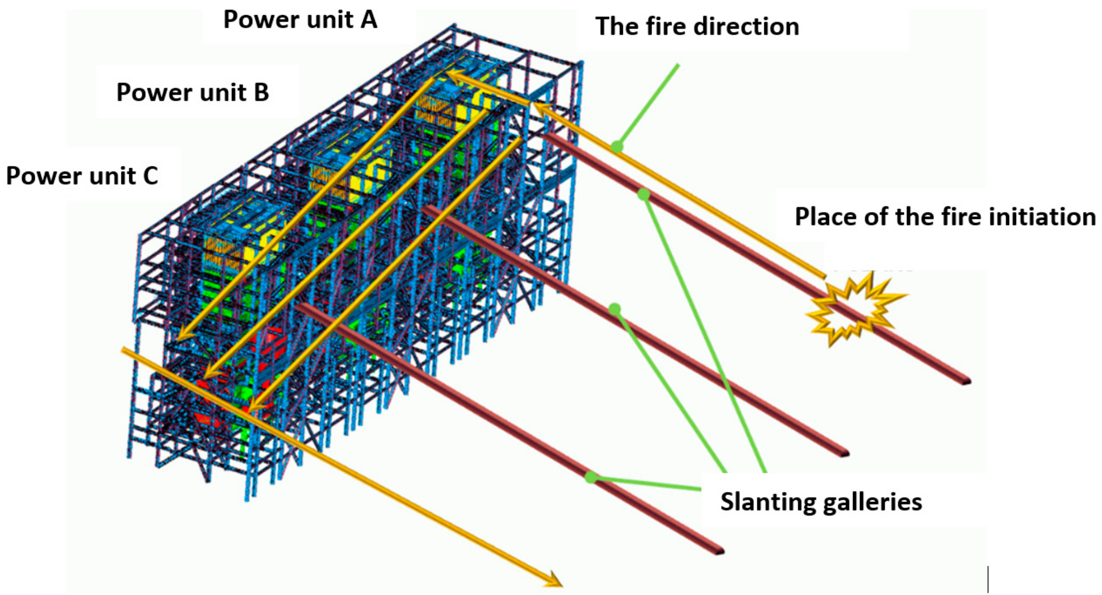
1. Introduction
- -
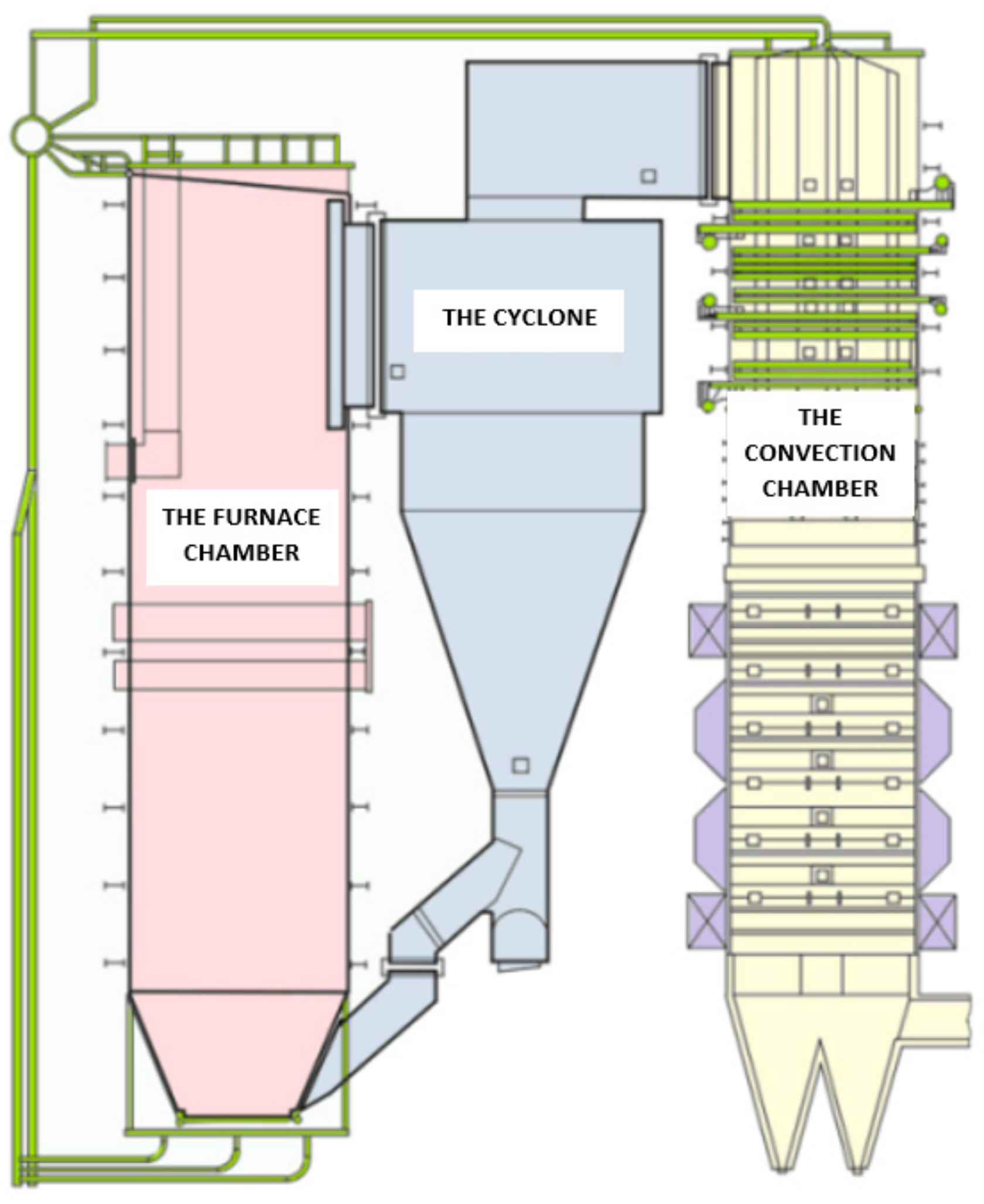
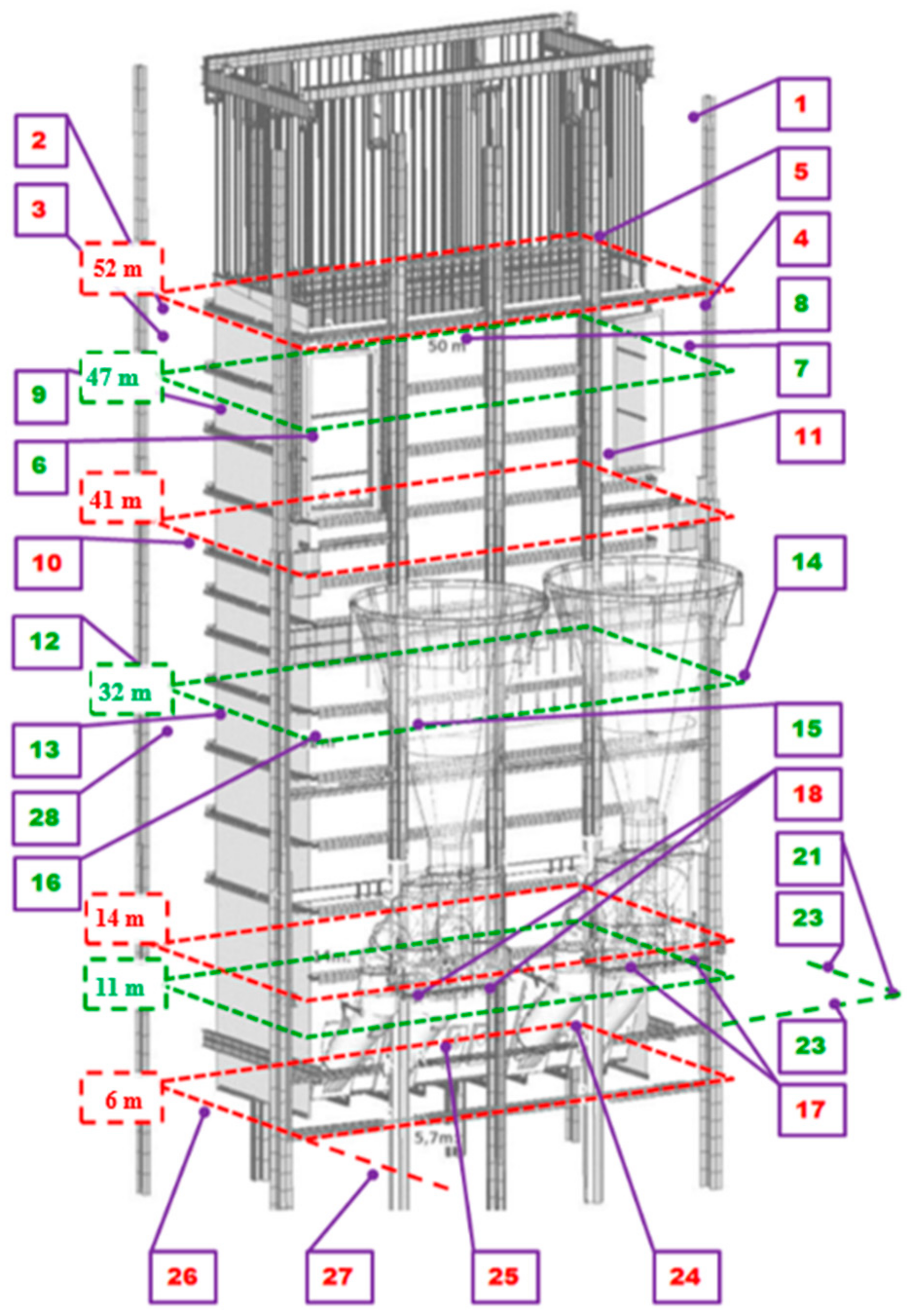
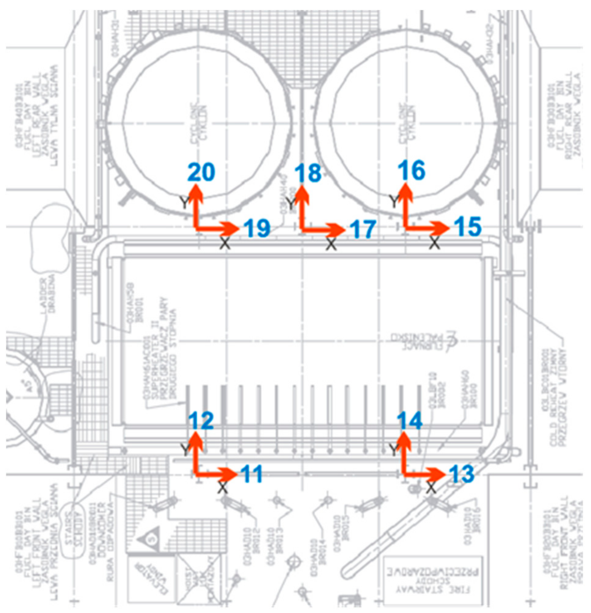
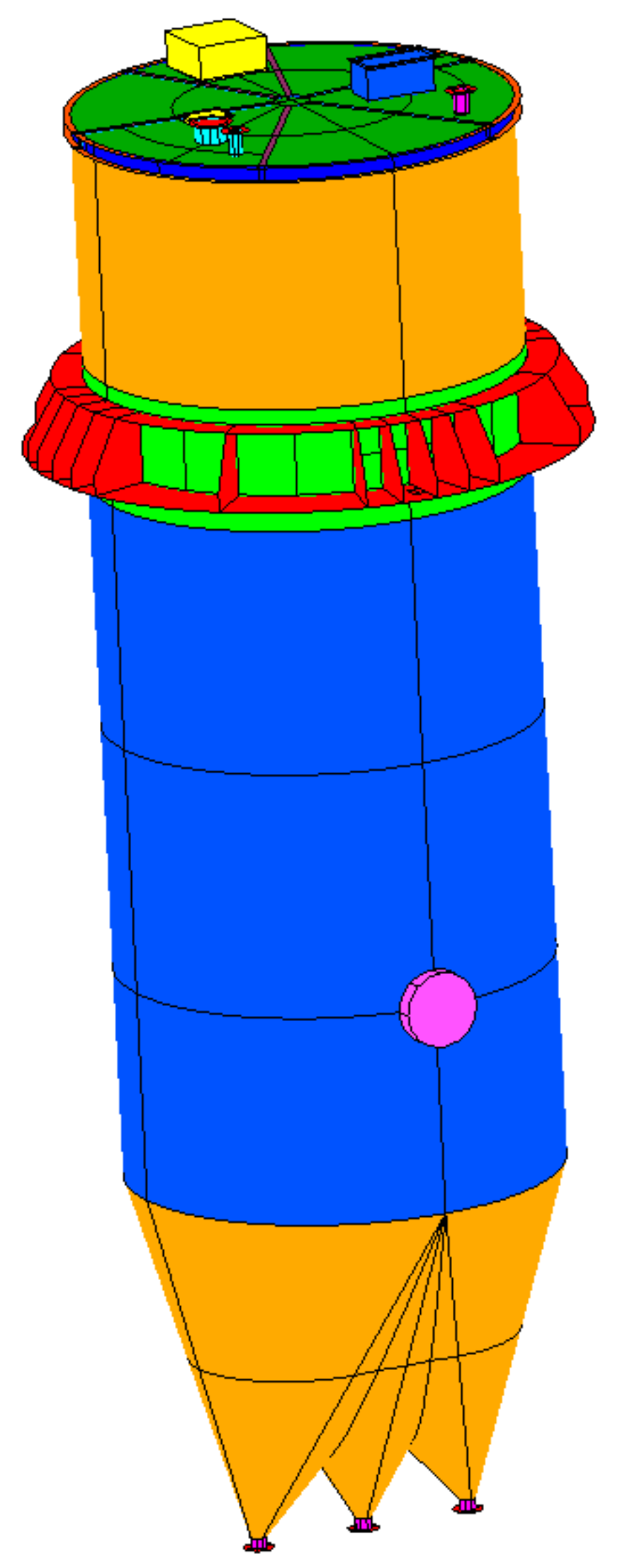
- Geometric measurements of the power unit’s main components: load-bearing structure, second pass chamber, cyclone, ash removal system, air ducts, accessory elements, etc.;
- -
- Identification of deviations from technical documentation and measurement results prior to the fire;
- -
- Non-destructive measurements of accessible welded joints in the power unit’s main components, load-bearing structure, second pass convection chamber, cyclone, ash removal system, air ducts, and auxiliary elements, etc., in order to find potential material discontinuities;
- -
- Evaluation of damage levels for selected spots of the investigated power unit’s elements after the fire;
- -
- Weld quality tests (continuity tests) regarding geometric welding imperfections [7];
- -
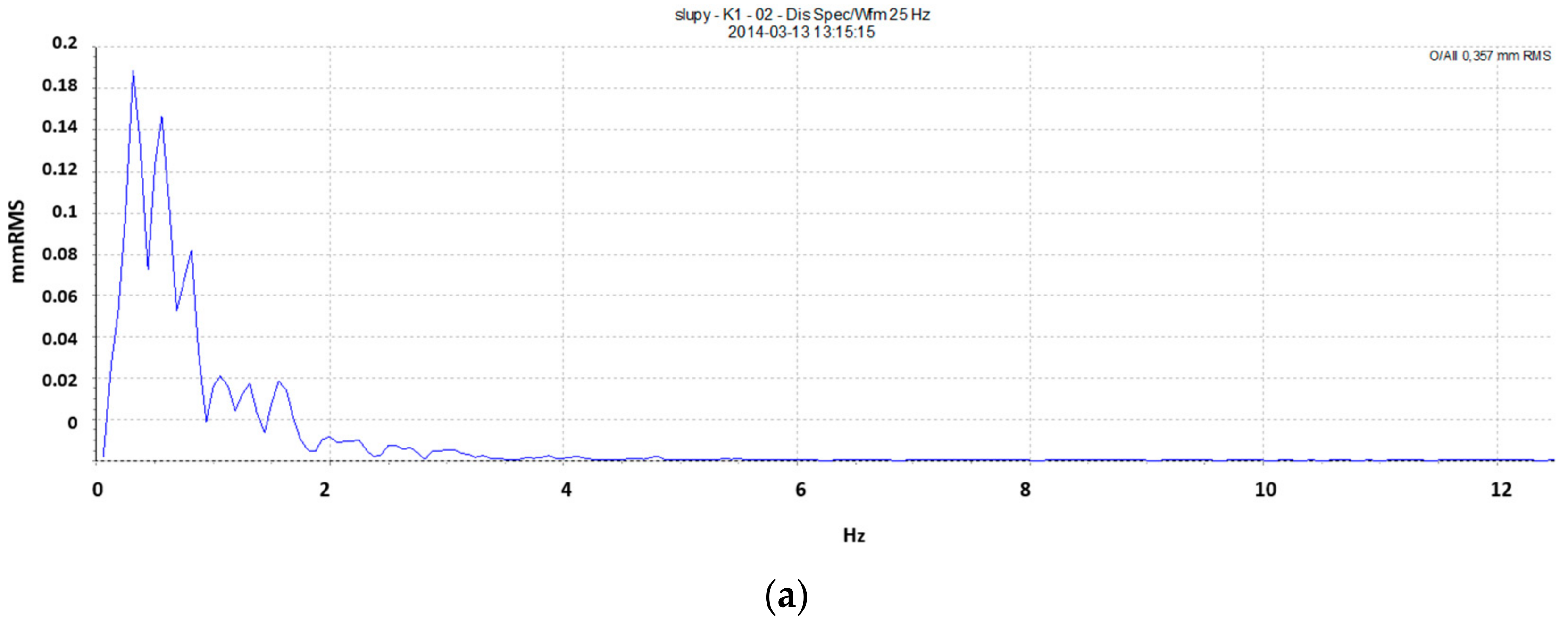
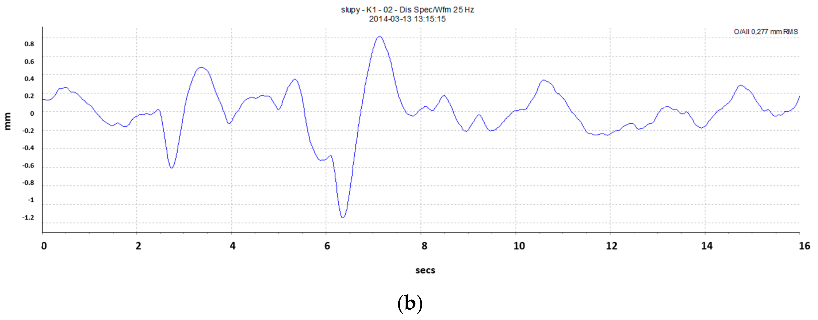
- Measurement of vibration levels for the power unit’s load-bearing structure in order to identify vibration amplitude;
- -
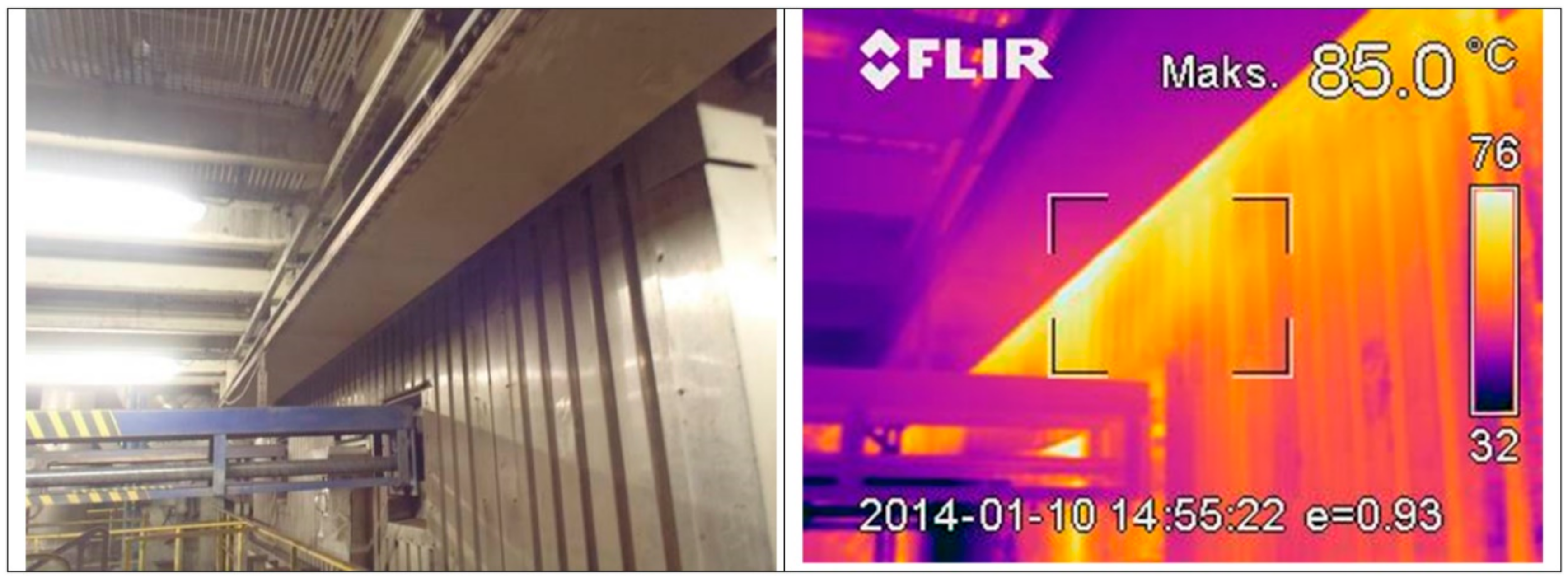
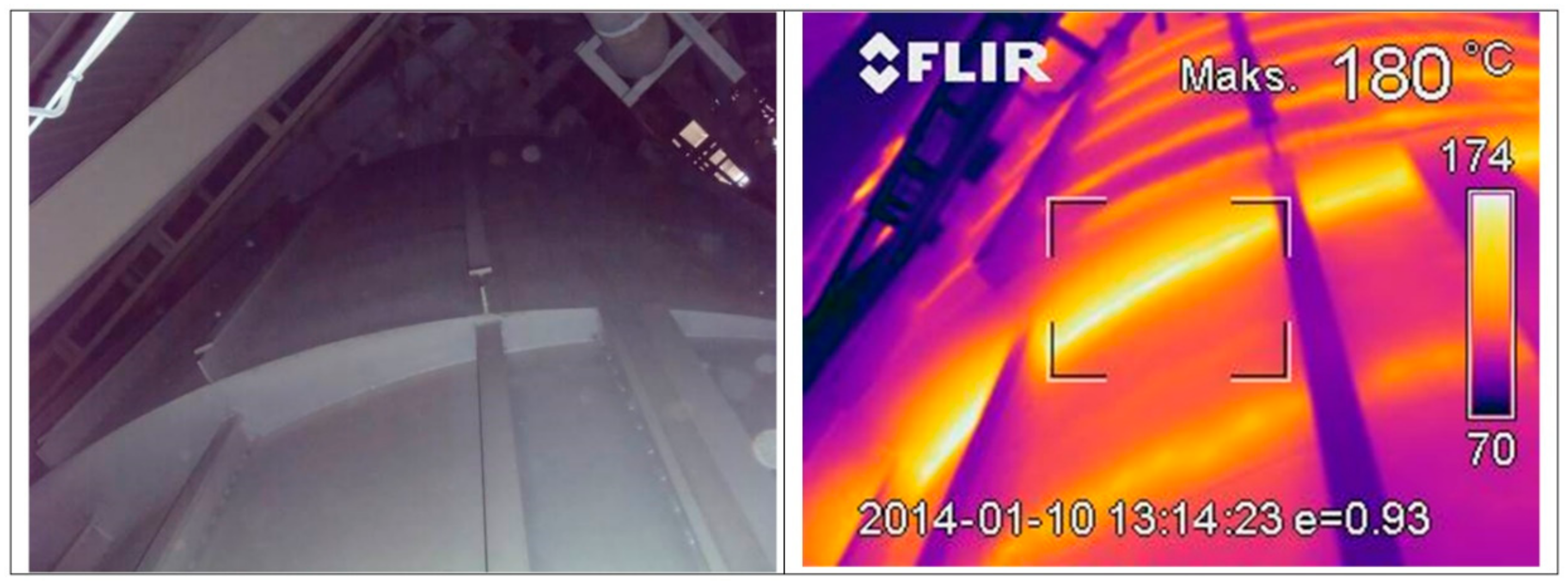
- Thermal imaging measurements of temperature distribution on particular elements of the inspected power unit;
- -
- Noise level measurements, in particular, selected spots of the power unit;
- -
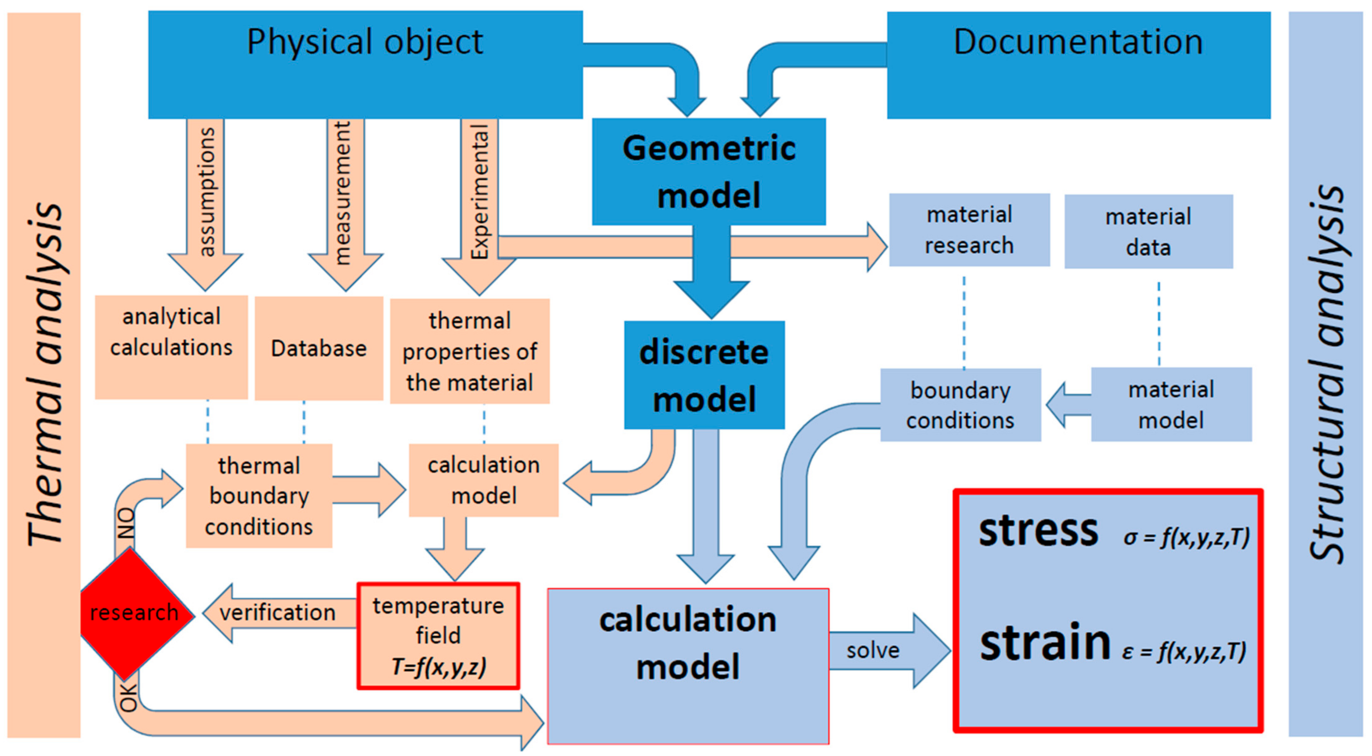
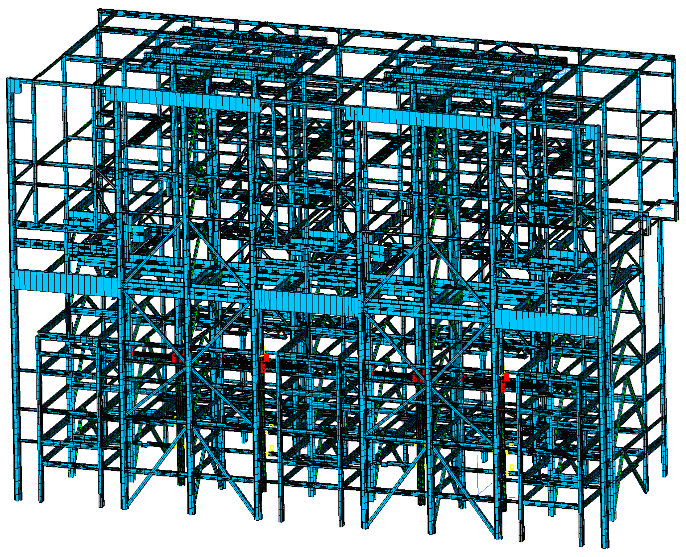
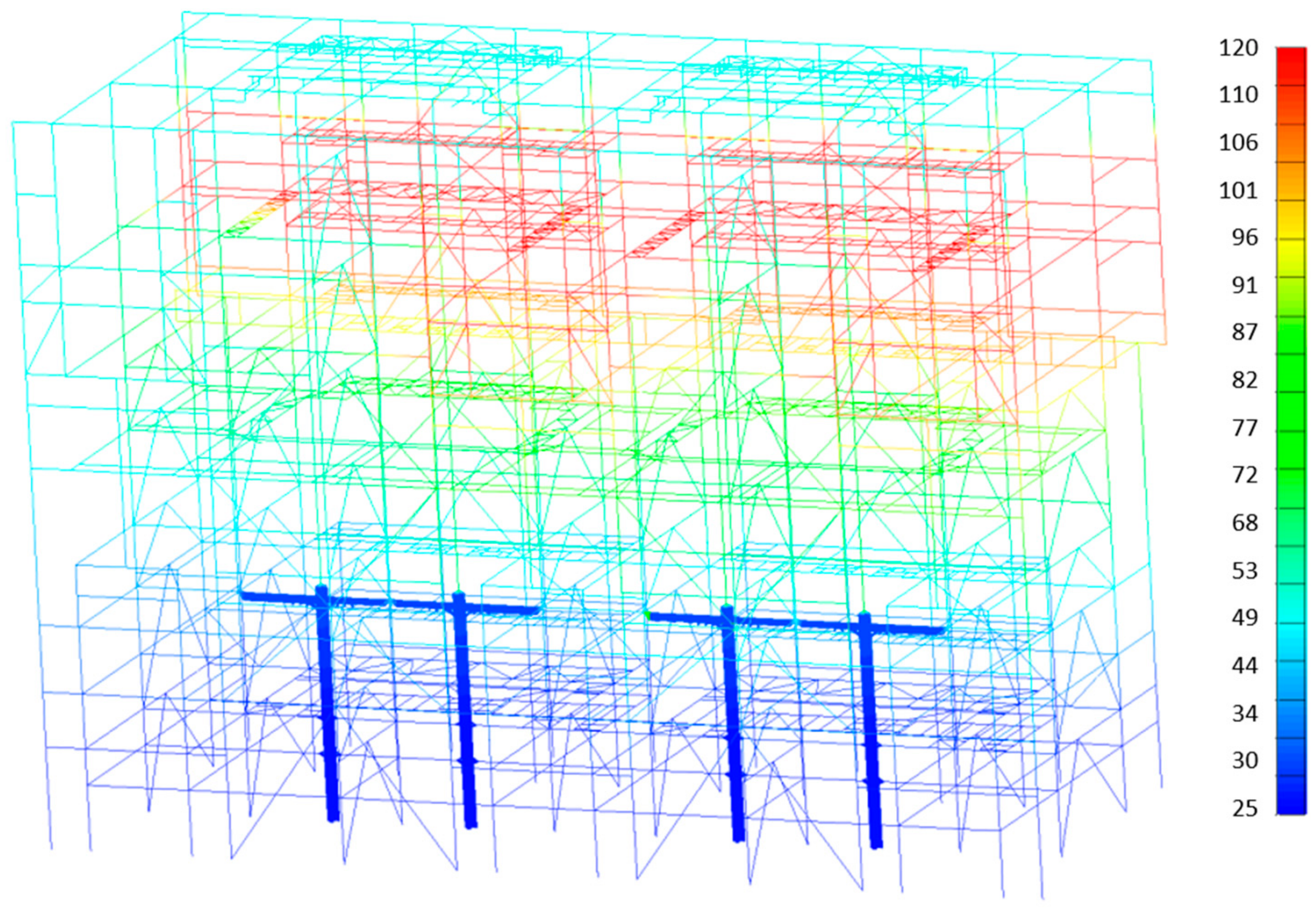
- Development of necessary selected computational models for the power unit’s components that allow for computer simulations of the impact of fire wave on the structure’s shape. Numerical analysis of the likelihood that load-bearing structure, furnace chamber and second pass, cyclone, ash removal system, air ducts, auxiliary elements, etc., suffered from permanent deformations caused by fire wave.
- -
- T—medium temperature;
- -
- λij—matrix of thermal conductivity coefficients;
- -
- ρ—density;
- -
- qv—heat generated in the medium;
- -
- c—pecific heat;
- -
- t—time.
2. Operating Parameters of Fluidized Bed Power Unit
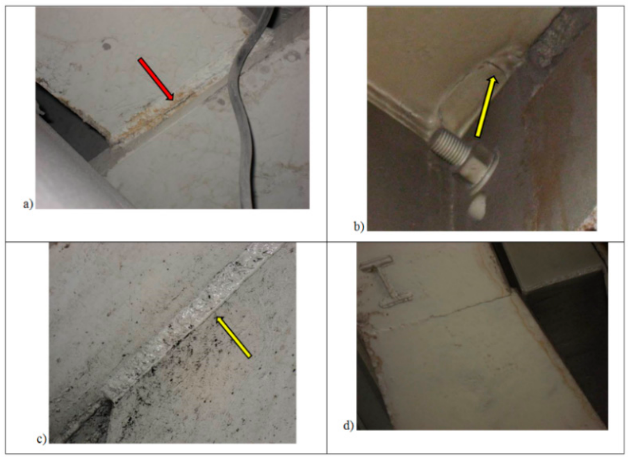
3. Non-Destructive Tests
- -
- Cracks of weld line in many places (Figure 5);
- -
- Insufficient quality of welding and weld repairs, welded joints made in inappropriate places;
- -
- Elastic buckling of lattice work in the load bearing structure;
- -
- Repairs done during power unit’s operation were not protected against corrosion;
- -
- Inappropriate bracing, which may cause stress concentration in the areas of their construction;
- -
- Additionally, a great number of welded joints is accumulated on a small area, which leads to the change in material structure, as a lot of heat is supplied and, therefore, the material loses its strength characteristics;
- -
- Deplanation (warping) of flanges and webs in support beams, as well as deformation of reinforcing ribs in I-beam girders;
- -
- Forbidden process holes (mount holes) in load-bearing girders and posts.
4. Measurement of Vibration Levels in the Load-Bearing Structure of the Power Units
5. Measurements of Temperature Distribution on Particular Elements of the Power Unit
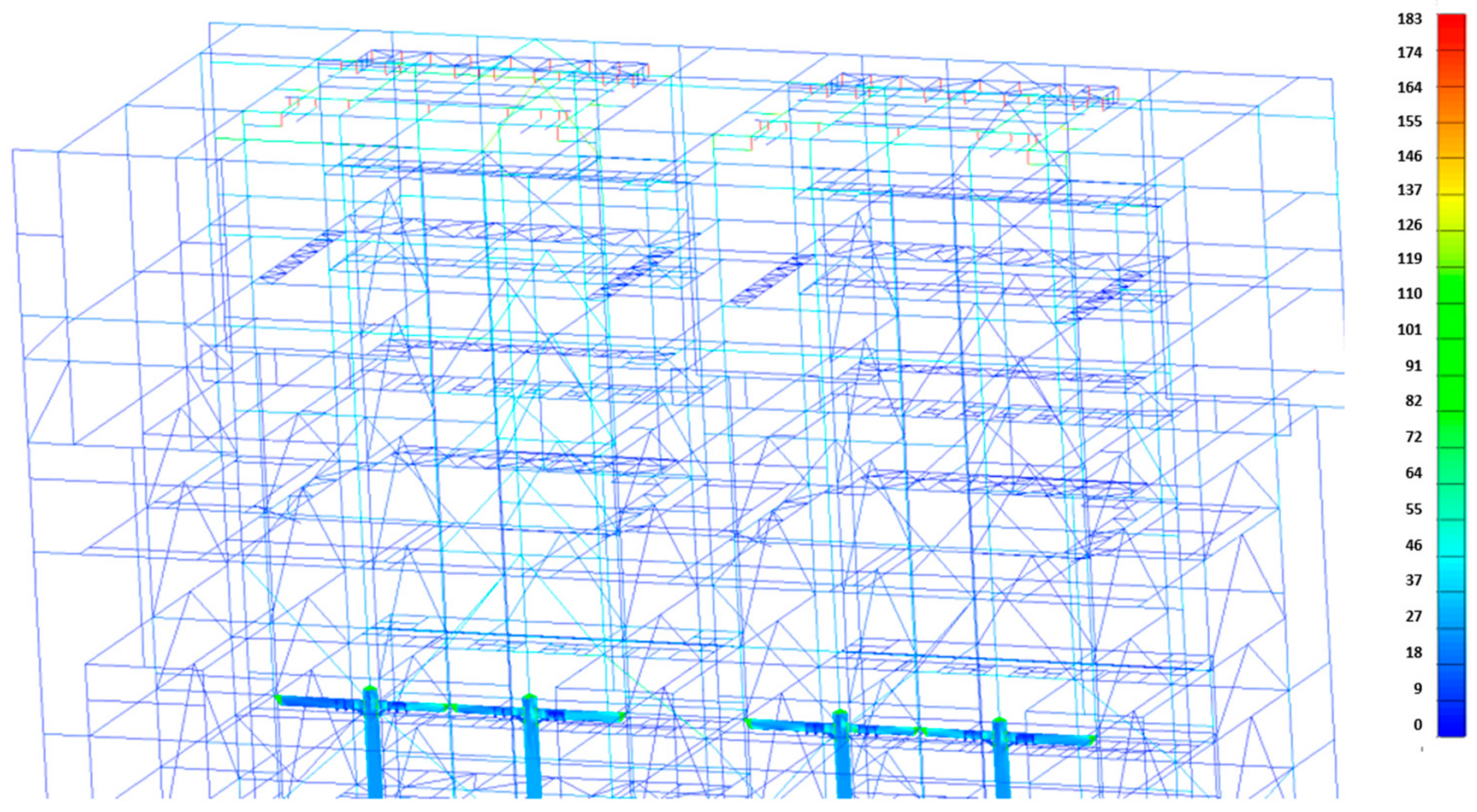
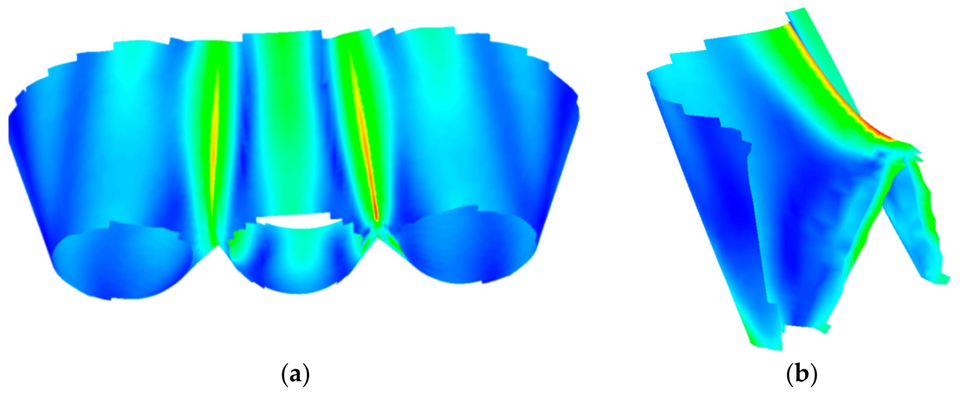
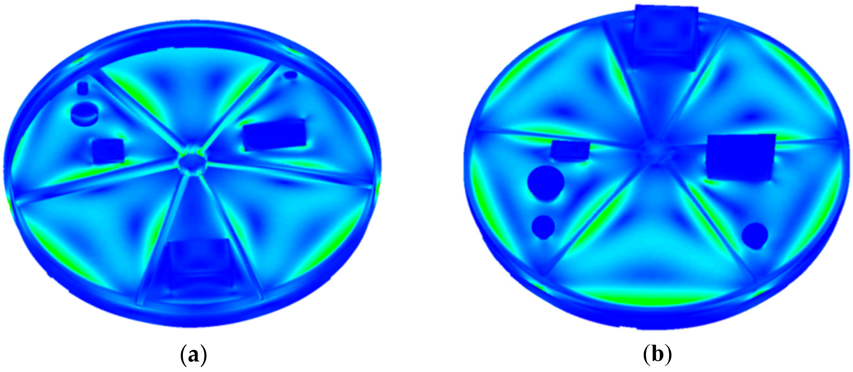
6. Strength Calculations for the Load-Bearing Structure of the Power Unit and Its Elements
- σred—reduced stress according to Huber and Mises [MPa];
- σdop—allowable stress assumed in the analysis [MPa];
- Re—yield strength of the container structure’s material [MPa].
7. Summary and Conclusions
- -
- Investigation of the damage that the passing fire wave caused to the load-bearing structure of the power unit’s elements, together with the equipment located in the technological line. As a parallel task, on-site inspections included the power unit’s main elements that remained in service for many years.
- -
- Problematic or damaged main elements found during inspection allowed us to estimate the technical condition of the investigated structure and to establish the scope of necessary repair works.
- -
- Inspections of welded joints were performed only in available places, on the unit’s main elements, i.e., on the load-bearing structure, second pass chamber, cyclone, ash removal system, air ducts, auxiliary elements, etc. As indicated in the article, much attention was paid to the levels on which the fire wave passed.
Author Contributions
Funding
Data Availability Statement
Acknowledgments
Conflicts of Interest
References
- Schröder-Hinrichs, J.U.; Baldauf, M.; Ghirxi, K.T. Accident investigation reporting deficiencies related to organizational factors in machinery space fires and explosions. Accid. Anal. Prev. 2011, 43, 1187–1196. [Google Scholar] [CrossRef] [PubMed]
- Zhu, Y.; Wang, D.; Shao, Z.; Xu, C.; Zhu, X.; Qi, X.; Liu, F. A statistical analysis of coalmine fires and explosions in China. Process Saf. Environ. Prot. 2019, 121, 357–366. [Google Scholar] [CrossRef]
- Czmochowski, J.; Górski, A.; Iluk, A.; Wyszyński, J. Numeryczna weryfikacja wytężenia przegrzewacza grodziowego kotła energetycznego. Syst. J. Transdiscip. Syst. Sci. 2002, 7, 105–112. [Google Scholar]
- Czmochowski, J.; Górski, A.; Paduchowicz, M.; Rusiński, E. Diagnostic method of measuring hanger rods tension forces in the suspension of the power boilers combustion chamber. J. Vibroeng. 2012, 14, 129–134. [Google Scholar]
- Kowalczyk, M.; Czmochowski, J.; Derlukiewicz, D. Diagnostic Models of the States of Developing Fault for Working Parts of the Excavator. Solid State Phenom. 2010, 165, 285–289. [Google Scholar] [CrossRef]
- Li, L.; Qin, B.; Ma, D.; Zhuo, H.; Liang, H.; Gao, A. Unique spatial methane distribution caused by spontaneous coal combustion in coal mine goafs: An experimental study. Process Saf. Environ. Prot. 2018, 116, 199–207. [Google Scholar] [CrossRef]
- Mi, C.; Li, W.; Xiao, X.; Berto, F. An energy-based approach for fatigue life estimation of welded joints without residual stress through thermal-graphic measurement. Appl. Sci. 2019, 9, 397. [Google Scholar] [CrossRef]
- Coimbra, R.N.; Escapa, C.; Otero, M. Comparative thermogravimetric assessment on the combustion of coal, microalgae biomass and their blend. Energies 2019, 12, 2962. [Google Scholar] [CrossRef]
- Zhou, C.; Gao, F.; Yu, Y.; Zhang, W.; Liu, G. Effects of Gaseous Agents on Trace Element Emission Behavior during Co-combustion of Coal with Biomass. Energy Fuels 2020, 34, 3843–3849. [Google Scholar] [CrossRef]
- Krolczyk, J.B.; Gapiński, B.; Krolczyk, G.M.; Samardžić, I.; Maruda, R.W.; Soucek, K.; Legutko, S.; Nieslony, P.; Javadi, Y.; Stas, L. Topographic inspection as a method of weld joint diagnostic. Teh. Vjesn. 2016, 23, 301–306. [Google Scholar] [CrossRef]
- Landowski, M.; Świerczyńska, A.; Rogalski, G.; Fydrych, D. Autogenous fiber laser welding of 316L austenitic and 2304 lean duplex stainless steels. Materials 2020, 13, 2930. [Google Scholar] [CrossRef] [PubMed]
- Górka, J.; Stano, S. Microstructure and properties of hybrid laser arc welded joints (laser beam-MAG) in thermo-mechanical control processed S700MC steel. Metals 2018, 8, 132. [Google Scholar] [CrossRef]
- Tabatabaeipour, M.; Hettler, J.; Delrue, S.; Van Den Abeele, K. Non-destructive ultrasonic examination of root defects in friction stir welded butt-joints. NDT E Int. 2016, 80, 23–34. [Google Scholar] [CrossRef]
- Vibrations, N.M.; Bergamo, E.; Fasan, M. Efficiency of Coupled Experimental—Numerical Predictive Analyses for Inter-Story Floors Under Non-Isolated Machine-Induced Vibrations. Actuators 2020, 9, 87. [Google Scholar]
- Shittu, S.; Li, G.; Zhao, X.; Akhlaghi, Y.G.; Ma, X.; Yu, M. Comparative study of a concentrated photovoltaic-thermoelectric system with and without flat plate heat pipe. Energy Convers. Manag. 2019, 193, 1–14. [Google Scholar] [CrossRef]
- Ren, K.; Chew, Y.; Zhang, Y.F.; Bi, G.J.; Fuh, J.Y.H. Thermal analyses for optimal scanning pattern evaluation in laser aided additive manufacturing. J. Mater. Process. Technol. 2019, 271, 178–188. [Google Scholar] [CrossRef]
- NX-Ideas. Producer: Siemens PLM Software, Distributor: ATA ENGINEERING INC. Available online: https://www.ata-plmsoftware.com/ (accessed on 22 February 2021).
- Doronin, S.V.; Reizmunt, E.M. Multi-Model Interval Estimators of the Strength State of Structurally Complex Load-Bearing Units of Production Equipment. Chem. Pet. Eng. 2018, 53, 604–609. [Google Scholar] [CrossRef]
- Ortlepp, R.; Ortlepp, S. Textile reinforced concrete for strengthening of RC columns: A contribution to resource conservation through the preservation of structures. Constr. Build. Mater. 2017, 132, 150–160. [Google Scholar] [CrossRef]
- Liu, J.; Xu, T.; Guo, Y.; Wang, X.; Frank Chen, Y. Behavior of circular CFRP-steel composite tubed high-strength concrete columns under axial compression. Compos. Struct. 2019, 211, 596–609. [Google Scholar] [CrossRef]


| Parameter | Value |
|---|---|
| Air excess factor l | 1.1–1.2 |
| Temperature in the bed, Tz | 850–870 °C |
| Burnup fraction | 96–98% |
| Sulfur fixation efficiency | 90% |
| NOx emission (NOx content in flue gas) | (Ca/S = 1.5–2.6) |
| 200–400 mg/m3 |
Publisher’s Note: MDPI stays neutral with regard to jurisdictional claims in published maps and institutional affiliations. |
© 2021 by the authors. Licensee MDPI, Basel, Switzerland. This article is an open access article distributed under the terms and conditions of the Creative Commons Attribution (CC BY) license (http://creativecommons.org/licenses/by/4.0/).
Share and Cite
Paduchowicz, M.; Górski, A. Identification of the Effects of Fire-Wave Propagation through the Power Unit’s Boiler Island. Energies 2021, 14, 1231. https://doi.org/10.3390/en14051231
Paduchowicz M, Górski A. Identification of the Effects of Fire-Wave Propagation through the Power Unit’s Boiler Island. Energies. 2021; 14(5):1231. https://doi.org/10.3390/en14051231
Chicago/Turabian StylePaduchowicz, Michał, and Artur Górski. 2021. "Identification of the Effects of Fire-Wave Propagation through the Power Unit’s Boiler Island" Energies 14, no. 5: 1231. https://doi.org/10.3390/en14051231
APA StylePaduchowicz, M., & Górski, A. (2021). Identification of the Effects of Fire-Wave Propagation through the Power Unit’s Boiler Island. Energies, 14(5), 1231. https://doi.org/10.3390/en14051231