Article

Mathematical Modeling of the Coaxial Quadrotor Dynamics for Its Attitude and Altitude Control

by
Wojciech Giernacki
1,*,
Jarosław Gośliński
2,
Jagoda Goślińska
3,
Tadeo Espinoza-Fraire
4 and
Jinjun Rao
5
1
Institute of Robotics and Machine Intelligence, Faculty of Control, Robotics and Electrical Engineering, University of Technology, Piotrowo 3a, 60-965 Poznan, Poland
2
Aisens Sp. z o.o., Lubeckiego 23A, 60-348 Poznań, Poland
3
Department of Rehabilitation and Physiotherapy, University of Medical Sciences, 28 Czerwca 1956 Str., No 135/147, 60-545 Poznań, Poland
4
Facultad de Ingenieria, Ciencias y Arquitetura, Universidad Juarez del Estado de Durango, Universidad Str., Filadelfia, Gomez Palacio, Durango 35010, Mexico
5
Shanghai Key Laboratory of Intelligent Manufacturing and Robotics, School of Mechatronic Engineering and Automation, Shanghai University, Shanghai 200444, China
*
Author to whom correspondence should be addressed.
Energies 2021, 14(5), 1232; https://doi.org/10.3390/en14051232
Submission received: 24 January 2021 / Revised: 12 February 2021 / Accepted: 17 February 2021 / Published: 24 February 2021
(This article belongs to the Special Issue Modelling of Aerospace Vehicle Dynamics)

Abstract

:
In this paper, an easily implementable coaxial quadrotor model and its validation on data from a real unmanned aerial vehicle (UAV), are presented. The proposed mathematical model consists of two parts: description of orientation and position of the UAV in the three-dimensional space. It takes into consideration the gyroscopic effect, influence of the Coriolis force, viscous friction and a several drag-like effects (blade flapping, rotor drag, translational drag and profile drag). In contrast to multirotor models available in the literature, this one is characterized by complementarity in relation to the available control techniques. Depending on selection of these techniques, the model can be narrowed (simplified) to meet the needs without the loss of behaviour adequacy to a real UAV.

1. Introduction

Coaxial quadrotor (coaxial quadcopter, octoquad) is usually defined as a multidimensional control plant, strongly non-linear, highly dynamic (because of the use of eight independent drive units located in pairs on the common cross-frame) and in general with parameters which are non-stationary. In some works, it is called octarotor, though it may be confusing since octarotors have in general a planar mechanical structure. Literature studies in the field of modeling coaxial quadrotors allow one to extract a number of key concepts. The first of them is accompanied by practical (constructional) terms, where the representation of a mathematical model of unmanned aerial vehicle (UAV) is intended to reflect the behaviour of a real quadrotor at the maximum simplification of its physical structure [1], neglect of certain aspects of aerodynamics—for instance: viscous friction [2] or drag-like effects [3]. In many cases, even basic laws of physics are sufficient for control purposes.
On the other side of available modeling concepts appears an approach, where one wishes to obtain a complete model—with possibly complete description of all physical laws that affect the quadrotor [4]. Thus object can be described using a wide range of mathematical techniques and benefits (e.g., quaternion notation [5]). This approach is justified and practically necessary, since it permits in a major way in simulation conditions to check aspects difficult to verify on the real UAV (e.g., aggressive maneuvers [6]) and those that are expensive. It may be noted that in order to seek for a “complete model” one can fall into the endless search for the sources and effects of physical laws that may still be relevant and have not been considered so far in already existing models of multirotor UAVs and coaxial units (analysis of the aerodynamic complexities [7], ground effect issues [8], hover/low-speed bare airframe dynamics [9], blade element momentum theory selected issues [10]). The passage of time provides new aspects for modeling (hitherto unknown phenomena, analyzed incorrectly or insufficiently precise). The technology development (measurements in wind tunnels [11], the use of Finite Element Method [12], new vision systems [13], parallelization of calculations, etc.) and software development [14] open new doors and opportunities for further research. Unfortunately, very complex models generate a high demand for computing power, which greatly limits their application in terms of time corresponding to a real coaxial quadrotor flight.
There are naturally also more consensual ways in modeling than the relationship: simple model vs. complex, and developed mathematical models are characterized more by their focused use (e.g., estimation and rejection of dynamic disturbances [15,16], payload improvement [17], multi-layered drift-stabilization [18]). A distinct center of gravity is placed for example in models developed for the purposes of control algorithms design (e.g., cascaded PD control [19], gain scheduling-based PID control [20], adaptive [21] and hierarchical integrating backstepping control [22], fault tolerant control [23], self-tuning fuzzy PID control [24], LQR control [25], multi-model control using fuzzy techniques [26]). Their complexity is lower than of the models used for simulation analysis only. Here the aim is to provide the highest control quality in a coaxial quadrotor, while modeling is limited only to the aspects needed for a potentially applied control algorithm [27]. Position and attitude control approaches from the last 10 years of UAV research may be found in [28].
Model simplification entails certain consequences, which however can be minimized through the use of estimation algorithms [29] to estimate neglected or unmeasurable values and state variables. Therefore, in accordance with the authors’ proposal, it is advantageous to adopt reasoning based on the search for balance between modeling, estimation and the used type of control. To make it easier, a new and relatively complex model is proposed. It is predefined in the designing of control algorithms and can be simplified or expanded with a more comprehensive analysis of the dynamics and electrical aspects [30].
To articulate contribution of the paper, to the authors’ best knowledge, this is the first journal paper about coaxial quadrotor UAVs that summarizes all necessary details of model (with the proposed important physical aspects) for control purposes in one place. The work presents a step-by-step method for modeling a quadrotor equipped with rotors whose number and location are nonstandard (rotors are in coaxial configuration and displaced in relation to the UAV’s center of gravity). From the idea, through the physical effects to mathematical conventions and formulas, the authors explain the model, tune it and validate it on real data from a coaxial quadrotor. This dynamical model takes into consideration the gyroscopic effect, influence of the Coriolis force, viscous friction and a several drag-like effects (blade flapping, rotor drag, translational drag and profile drag). In contrast to multirotor models available in the literature, this one is characterized by complementarity in relation to the available control techniques. Depending on selection of these techniques, the model can be narrowed (simplified) to meet the needs without the loss of behaviour adequacy to a real UAV.
The article is organized as follows: Section 2 presents principles of UAV control and the ways of defining quadrotor position and orientation in the 3D space. Section 3 contains the proposed coaxial quadrotor model. A brief description of the physical phenomena affecting the UAV, is given. Section 4 presents validation tests with the use of a proposed model of the Falcon V5 robot. Conclusions are provided in Section 5.

2. Coaxial Quadrotor Control Basics

2.1. Physical Construction of Coaxial Quadrotor

Each coaxial quadrotor is a multirotor UAV equipped with eight propellers. They are placed coaxially on the robot’s frame [31] (see Figure 1). This results in an increased payload at the similar mechanical structure compared to classical quadrotor. Thrust and torque are generated by the rotational movement and appropriate geometrical construction of propellers mounted directly on the Brushless Direct Current (BLDC) motor.
The propeller rotates in one direction, which is due to a constant pitch of the blade. Changes of voltages transmitted to the BLDC motor, i.e., Pulse-Width Modulation (PWM) duty cycles from the Electronic Speed Controller (ESC), result in corresponding changes of the rotational speed of the propeller.
Avionics of the UAV is based first and foremost on measurements from the available inertial measurement unit (IMU) containing three gyroscopes and triaxial accelerometer and magnetometer, which are used for the stabilization of the UAV’s position and orientation. More precisely, gyroscopes are used to determine the orientation relative to the base, and accelerometers with magnetometers are used to reset the gyro drift. Gyroscopes provide measurements of the angular velocity in the local coordinate system of the quadrotor, while accelerometers and magnetometers provide measurements of linear acceleration and magnetic induction, with respect to the global coordinate system ( EF —Earth Frame), projected onto the axes of the local coordinate system ( BF —Body Frame).

2.2. Change of the UAV’s Position and Orientation

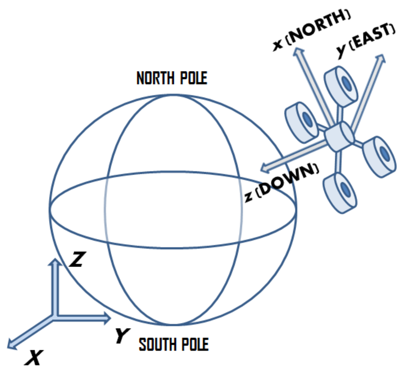
The coaxial quadrotor can be considered as a flying robot with six degrees of freedom (DOFs). Three degrees are used to describe position, and the next three, orientation (via Euler or so-called Tait–Bryan angles). These angles allow the mathematical description to be converted from BF to the EF coordinate system. In the modeling process presented in the next chapters, the North–East–Down (NED) configuration of the reference system is used (Figure 2).
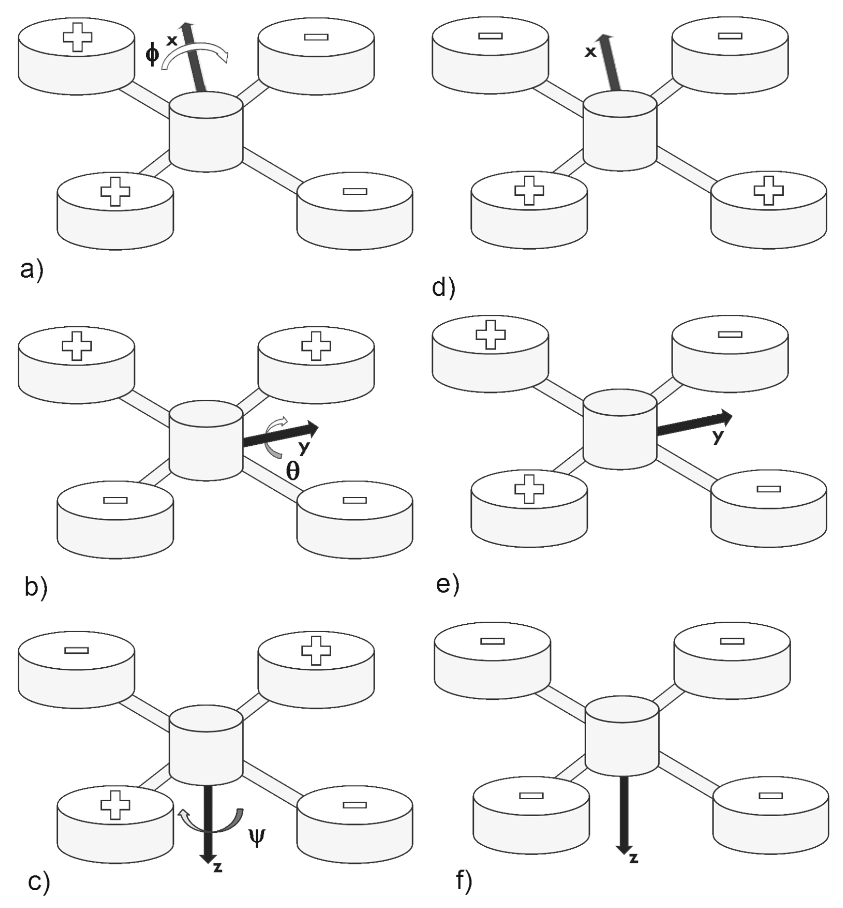
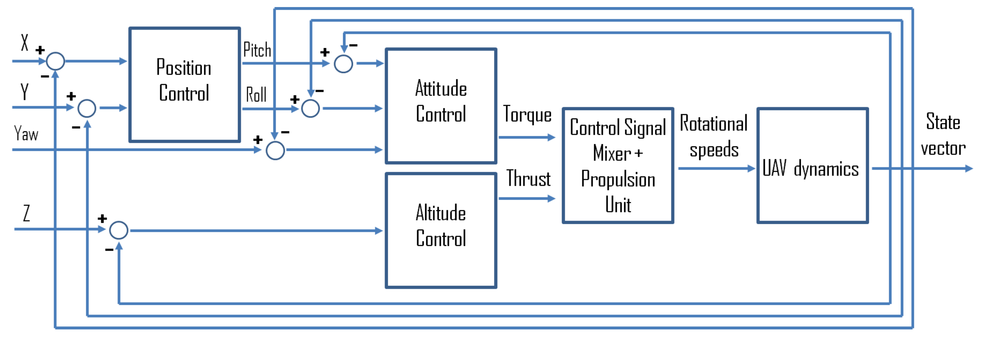
Every change of the UAV’s position x , y , z expressed in relation to the beginning of the global coordinate system X , Y , Z , and every change of its orientation (rotations about Roll, Pitch and Yaw angles) measured in the local coordinate system and implemented in relation to the axis of the global coordinate system from Figure 2, is possible only by changing the rotational speed of appropriate propulsion units (and thus by the change of thrust and torque). Figure 3 shows how this is accomplished. From the perspective of control, the preferred solution is the architecture from Figure 4 which is based on a cascade control loop realization of movement and orientation of the UAV.
Thanks to this solution (cascade control structure), the problem of control of a plant with six DOFs becomes simplified to the problem of X, Y, Z position control with automatic conversion of proper orientation and adjustment of rotational speed that will ensure this. Six controllers are used for this purpose.
Note, that an interesting approach to the problem of UAV attitude control in cascade control structure, when there are discrepancies in the characteristics of the 4 actuators (electrical motors and propellers) with the use of cascade control strategy with a PD controller in the inner loop (to achieve stabilization), and PI controller in the outer loop (to ensure disturbance rejection), one may find in [32]. In [33], a model of constrained control scheme to steer an UAV to the desired position while ensuring constraints satisfaction at all times (based on the Explicit Reference Governor framework), is presented.
In order to facilitate the tuning of real UAV controllers, mathematical modeling based on physical phenomena affecting the coaxial quadrotor and physical modeling of the robot itself is used. In following sections key aspects necessary to build the models of coaxial quadrotor are shown.

3. The Coaxial Quadrotor Model

The mathematical model of coaxial quadrotor proposed by the authors describes the orientation and position of a robot in the 3D space. The basic formulas are as follows:
ω ˙ = I 1 τ ω × ( I ω ) τ gyro τ d τ t ,
v ˙ = 1 m f f g f co f d f t ,
where left sides of (1) and (2) are angular and linear accelerations respectively. The components of (1) are input torque (from propellers), gyroscope torque due to the robot’s frame and propulsion units system, as well as aerodynamical effects and friction ( τ d and τ t ). In case of Equation (2), the elements are similar to the torques (those with the same subscripts), extended with projected gravitational force and Coriolis force ( f g and f c o , respectively). The presented model is explained in the further part of the section. It is divided into two basic parts: the position model (relates to positions, linear velocities and accelerations in reference and local Cartesian coordinate systems) and the orientation model (describes angular velocities and angles in X, Y and Z axis).

3.1. Euler Angles

The Formulas (1) and (2) describe the relation between the quadrotor state and input forces/torques. These equations are expressed in the local coordinate system. It means that all state variables are directly linked with the UAV. However, in case of control tasks, inertial coordinate systems are used. Thus, one needs to transfer the quadrotor state to the reference system chosen based upon the purposes. Basically, two methods are used: quaternions and Euler angles (or Tait–Bryan angles). A rotation matrix transferring an arbitrary vector from BF to EF is needed [34]. In this work, the authors have chosen the flight notation (“3–2–1”), which assumes that the final rotation matrix R e b is a result of multiplication of three basic rotation matrices, in the following order:
R e b = R x ( ϕ ) R y ( θ ) R z ( ψ ) .
Note that the basic rotation matrix in a given axis transfers a vector from an old coordinate system SF to a new one, SF (see Remark no. 1 in Appendix A):
v { S F } = R x | y | z v { S F } .
This rule enforces the following rotations matrices forms:
R x ( ϕ ) = 1 0 0 0 c o s ϕ s i n ϕ 0 s i n ϕ c o s ϕ ,
R y ( θ ) = c o s θ 0 s i n θ 0 1 0 s i n θ 0 c o s θ ,
R z ( ψ ) = c o s ψ s i n ψ 0 s i n ψ c o s ψ 0 0 0 1 .
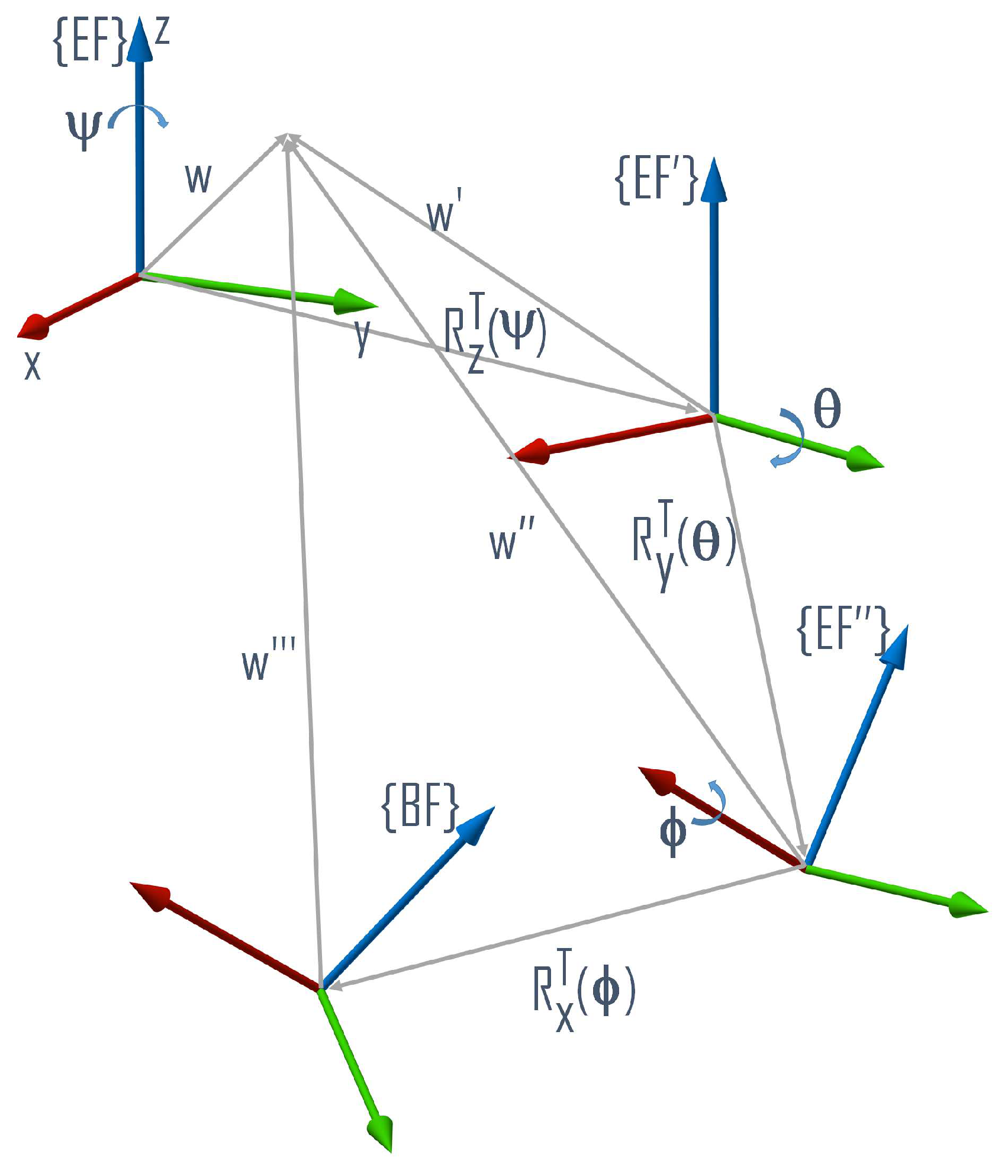
The “3–2–1” assumes that during the rotations, the following steps are performed (Figure 5):
  • Rotation Yaw about angle ψ in the z axis of the EF (global coordinate system),
  • Rotation Pitch about angle θ in the y axis of the EF (new coordinate system),
  • Rotation Roll about angle ϕ in the x axis of the EF (new local coordinate system), yielding BF as a product.
Under this assumption, the transformation matrix given in (3) may be written as:
R e b = R x ( ϕ ) R y ( θ ) R z ( ψ ) = = c θ c ψ c θ s ψ s θ s ϕ s θ c ψ c ϕ s ψ s ϕ s θ s ψ + c ϕ c ψ s ϕ c θ c ϕ s θ c ψ + s ϕ s ψ c ϕ s θ s ψ s ϕ c ψ c ϕ c θ ,
where s and c stands for s i n and c o s , respectively.
In case of control tasks, the reverse transformation is needed. The required matrix R b e transforms any given vector v b from BF to EF , yielding v e EF . Since the R e b is an orthonormal matrix, it can be written that:
R e b = R b e T .
In the notation, Euler (or Tait–Bryan) angles vector θ is as follows:
θ = ϕ θ ψ T .
Euler angle vector θ from Equation (16) is used in the paper (in angular velocities derivation) for the definition of the transformation matrices.

3.2. Angular Velocities

Euler’s notation presented in the previous subsections is the base for the mathematical formulas for angular velocities of a coaxial quadrotor. The vector θ ˙ (Euler rates) expresses the projections of the UAV’s angular velocities (written in the BF ) onto the axes of the EF . It is an alternative notation to ω BF (from gyroscopes one may directly measure the angular velocity ω ), but to obtain the Euler rates, one must project ω on axes of the EF .
The algorithm for the Euler rates calculation has been described in [35] (for more information see also Remark no. 2 in Appendix A). The first step is the calculation of the angular velocity ω in a local coordinate system BF :
ω = ω x ω y ω z T = = ϕ ˙ 0 0 + R x ( ϕ ) 0 θ ˙ 0 + R x ( ϕ ) R y ( θ ) 0 0 ψ ˙ .
A convenient representation of (11) may be given in a matrix form:
ω = P e b θ ˙ ,
where:
P e b = 1 0 s θ 0 c ϕ s ϕ c θ 0 s ϕ c ϕ c θ .
Since an inverse transformation ( BF EF ) is needed, the P b e matrix must be derived:
P b e = ( P e b ) 1 = 1 s ϕ s θ c θ c ϕ s θ c θ 0 c ϕ s ϕ 0 s ϕ c θ c ϕ c θ .
The matrix P b e is used directly to determine the Euler rates:
θ ˙ = P b e ω .
Note that in case of multirotor sensory system, the value of ω is provided from measurements.

3.3. Angular Acceleration

In the derivation it is assumed that the UAV is considered as a perfectly stiff object in the 3D space. That allows the description of the angular acceleration of the UAV to use the basic Euler equation for the motion of a rigid body ([34], p. 168), and in general form one can write that:
d L d t + ω × L = τ ,
where angular momentum L for a rigid body is
L = I ω .
Based on the constancy of the inertia moments and by substituting (17) to (16), one obtain the torque equation:
τ = I ω ˙ + ω × ( I ω ) .
Using (18), the angular acceleration is written as:
ω ˙ = I 1 ( τ ω × ( I ω ) ) .
Equation (29), however, due to the gyroscopic effect, viscous friction and several drag-like effects, must be extended (described in the following subsections) to the complete form presented in subsection Equation (1).

3.3.1. Input Torques

The forces generated by the propellers can be written as
f i = 0 0 b i ω i 2 T ,
where f i BF and b i are the force and thrust factor of the i-th propulsion unit, respectively.
The input torque vector τ is a sum of torques ( τ i ) due to subsequent propellers. A particular i-th torque defined as a cross-product of the i-th propeller position ( p i ) in respect to the BF (22) and the i-th force (20) can be calculated as
τ i = τ x i τ y i τ z i T = p i × f i ,
p 1 / 2 = l w l w h T ,
p 3 / 4 = l w l w h T
p 5 / 6 = l w l w h T ,
p 7 / 8 = l w l w h T ,
where l w = 2 2 l and l-arm’s length in the UAV cross-frame, h-distance between the arm and propeller’s plane in respect to the Z axis of BF .
Equation (21) covers the torques generated in the X and Y axes in BF , while the Z axis will also suffer from the reaction torques, given in (23):
τ z = d 1 ( ω 2 2 + ω 3 2 + ω 6 2 + ω 7 2 ) d 2 ( ω 1 2 + ω 4 2 + ω 5 2 + ω 8 2 ) .
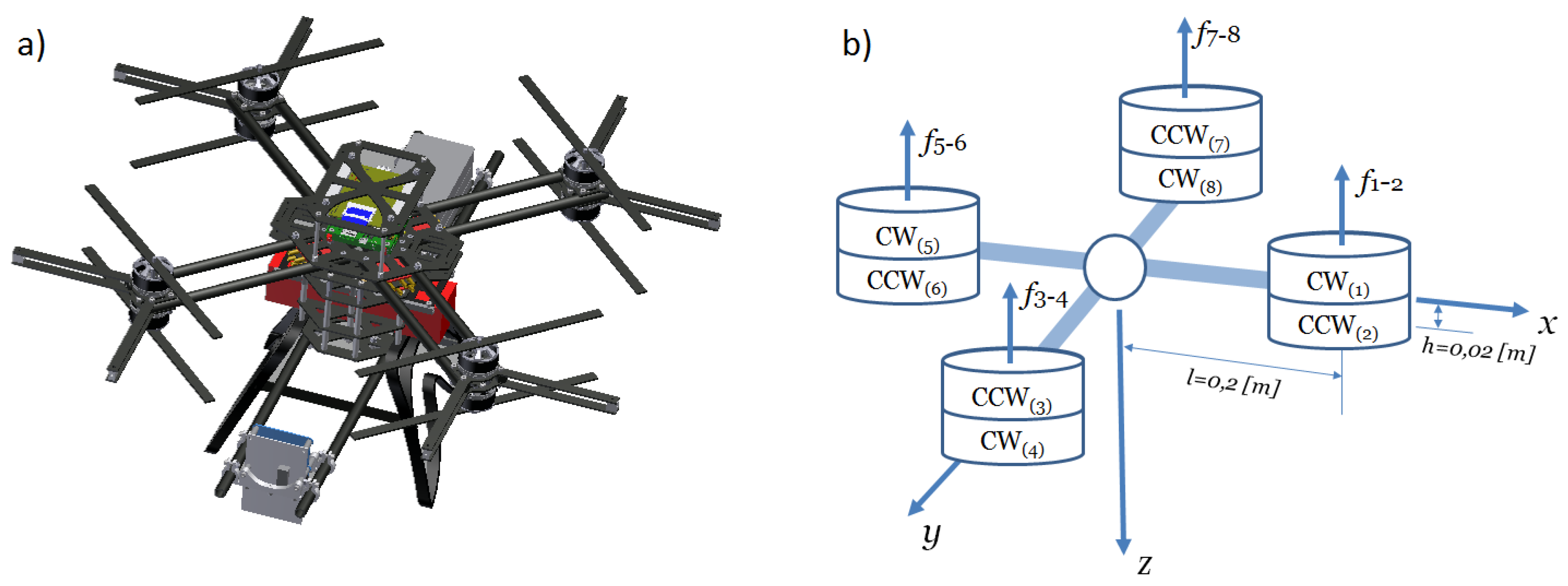
In Equation (23), the parameters d i refer to the reaction torque gains. Two of them are introduced, which stems from the opposite type of propellers system. Propellers 1, 4, 5, 8 rotate clockwise (CW) and propellers 2, 3, 6, 7 rotate counterclockwise (CCW) (Figure 6). Note that CW rotation contributes to counterwise reaction torque.
ω ˙ = I 1 ( τ ω × ( I ω ) ) .

3.3.2. Gyroscopic Effect

The gyroscopic effect is described by the basic equation of the gyroscope:
τ g y r o = ω p × L r ,
where: L r —rotors–propellers angular momentum vector, ω p —angular velocity precession vector.
Each object with a spinning mass is subjected to a gyroscopic precession motion effect, so it can be written that
ω p = ω .
Similarly to the angular momentum of the robot frame, given in Equation (17) the angular momentum of the propulsion unit can be expressed as follows:
L r = I r ω r .
In Equation (27), I r scalar denotes simplified motor–propeller inertia, while ω r refers to the sum of the rotors’ angular velocities (in the Z-axis). The angular momentum vector (27) is obtained by multiplying the moment of inertia ( I r ) by the rotor’s angular velocity about the axis where the rotation occurs ( ω r ):
ω r = 0 0 ω 1 ω 2 ω 3 + ω 4 + ω 5 ω 6 ω 7 + ω 8 .
The rotor angular velocity vector ( ω r ) contains zeros for the components in the axes X, Y and the sum of the rotors angular velocities ω i (where i varies in the range of [ 1 , 8 ] ) in the Z axis. Knowing L r and ω r , Equation (25) can be rewritten as follows:
τ g y r o = ω x ω y ω z × 0 0 I r ω r z = ω y I r ω r z ω x I r ω r z 0 .

3.3.3. Viscous Friction

According to [36], friction model for air flows has to include viscous friction. In a standard form, with respect to the UAV’s angular velocity, viscous friction can be expressed as (30):
τ t = b w ω ω ω = b w ω x ω x 2 b w ω y ω y 2 b w ω z ω z 2 .

3.3.4. Drag-Like Effects

As it may be found in [37], there are a number of drag-like effects: blade flapping, rotor drag, translational drag, profile drag and parasitic drag (which may be ignored for speeds up to 10 m / s [37]).
The blade flapping effect is especially noticeable on multirotor UAVs, when its rotors undergoes translational motion. This effect is seen on the rotor’s tip path plane which deviates by an angle called as flapping angle β f l a p . More information about the flapping effect can be found, among others in [38], and further in the article, the final form of the equation for the i-th rotor is introduced:
δ i = f i A f l a p v p ω i + B f l a p ω ω i ,
where v p = v x v y 0 T is horizontal velocity in BF , and A f l a p , B f l a p are lumped parameter matrices defined as:
A f l a p = 1 r A 1 c A 1 s 0 A 1 s A 1 c 0 0 0 0 ,
B f l a p = B 2 B 1 0 B 1 B 2 0 0 0 0 ,
where r—rotor radius, A 1 c and A 1 s are positive scalar constants that depend on the geometry of the rotor blades (see Equation (4.45) and Equation (4.47) in [39]). In practice agile coaxial quadrotors require stiff rotors in order that rotation in the airframe is directly translated into rotation in the thrust vector. That is to reduce the magnitude of B f l a p [40]. Note that parameters: A 1 c , A 1 s , B 1 , B 2 needs to be identified from flight tests [38]. In the paper [29], the authors provided example of the identification of matrix parameters using the Particle Swarm Optimization method for a typical quadrotor attached on a special testbed that allows to record measurement data for the used propulsion units with propellers, on which drag-like effects were analyzed.
The second important drag-like effect is so-called rotor drag, which usually occurs in small multirotor UAV, where its rigid or semirigid rotor blades causes an inbalance in flapping forces. Mathematically it is modeled as:
D I = K I v p ,
where K I is a scalar parameter and v p -planar velocity.
Another effect depends on speed in the air and is called translational drag. It is observed when the air is redirected from any translational movement to the downward of BF . During slow movements (according with [37]), this effect can be modelled via following equation:
D T = K T 1 v p .
Considering fast maneuvers, one needs to add the air velocity v i induced by the i-th rotor:
D T = K T 2 ( v z + v i ) 4 v p ,
where K T 1 , K T 2 are scalar parameters, and v z is translational the speed in z axis.
There are two more important drag-like effects: parasitic drag and profile drag (37). The first one comes from nonlifting surfaces of the multirotor UAV only for high speeds (>10 m / s ). Therefore one can ignore it in the case considered in this paper [37] and applied in to the model just the profile drag. This drag effect is gained with the transverse velocity of the rotor blades in the air and can be formalized as:
D P = K P v p ,
where K P is a lumped parameter.
After considering all of the above-mentioned drag effects, the total drag effect force acting on the i-th rotor is:
D i = δ i + D I + D T + D P ,
and the torques corresponding to them, for the i-th rotor are:
τ D i = p i × D i .
The net torque τ D is the sum of all τ D i , where i = 1 , , 8 and i Z .

3.3.5. Orientation Model—Angular Acceleration

The final form of upgraded Euler’s equation given as (1) is:
τ = I ω ˙ + ω × ( I ω ) + τ g y r o + τ d + τ t = I ω ˙ + ω × ( I ω ) + + ω × I r ω r + i = 1 8 τ d i + b w ω ω ω .
In (40), the resulting quantity is the angular acceleration, so after simple algebra it may be written that:
ω ˙ = I 1 ( τ ω × ( I ω ) ω × I r ω r + i = 1 8 τ d i b w ω ω ω ) .
Analysis of previous and present sections sugests that using measurements of angular accelerations from gyroscopes (to retrieve the UAV’s orientation in EF ), one needs to integrate angular acceleration and after that, transform obtained result into the Euler rates (15). Note that Euler (or Tait–Bryan) angles are given by the second integration of the Euler rates.

3.4. Linear Acceleration

The basic equation for linear acceleration includes the sum of forces acting on a body with a certain mass, which stems from Newton’s law. Since the UAV can rotate and translate in 3D, the dynamics of both of these types of motion has to be captured. There are several types of forces explained below. All of them act directly on the UAV in BF .

3.4.1. Thrust Force

Thrust force or simply input force is the sum of all forces generated by the propulsion units. If the force of the i-th rotor is given as f i :
f i = 0 0 b i ω i 2 T ,
then the total thrust force vector f is as follows:
f = i = 1 8 f i .
Note that b i is the thrust coefficient of the i-th propeller. These parameters may change according to the spatial location of the propellers (especially in coaxial multirotors), and what is more, they can differentiate the type of flight, for example the ground effect can be reflected in a proper change of b i .

3.4.2. Gravitational Force

The force of gravity is normally provided in EF . Since the NED is chosen as the configuration of EF , the gravity force is as follows:
f g e = 0 0 m g T .
In BF , a projection of f g e is used:
f g = f g b = R e b f g e = m g sin θ m g sin ϕ cos θ m g cos ϕ cos θ .

3.4.3. Coriolis Force

The Coriolis force is a pseudo force, which occurs only in the local coordinate system:
f c o = 2 m ω × v .

3.4.4. Drag Forces

Drag forces are due to aerodynamic effects, explained in the previous subsection. The f d is a sum of all drag-like effects of all propulsion units:
f d = i = 1 8 D i .

3.4.5. Friction in Linear Motion

The friction force f t is results from the viscous drag:
f t = b v v v v = b v v x v x 2 b v v y v y 2 b v v z v z 2 .

3.4.6. Linear Motion Model—Linear Acceleration

The overall model of linear motion is given by (49). Note that the left side of the equation is a linear acceleration in the local coordinate system, i.e., v ˙ BF .
v ˙ = 1 m ( i = 1 8 f i R e b f g e + 2 m ω × v + i = 1 8 D i b v v v v ) .
It is important to mention that the presented mathematical model is still just a simplification, which means that in general, the main sources of potential uncertainties and disturbances need to be considered, analyzed and remembered in its application for control purposes. The main source of disturbances is the flapping effect, while the key role in the model uncertainty is played by thrust coefficients which change in time, and dynamic states due to air stream coupling between coaxial propellers. The impact and scale of uncertainty, as well as unmeasured (stochastic) disturbances have been assessed in experiments on data from a real robot (Section 5, Experiment no. 3).

4. Model Validation

4.1. Introduction

In the following part, the paper presents test results obtained for the Falcon V5 flying robot (see Figure 7), which is the octoquad based on a X-shape skeleton construction made of Carbon Fiber Reinforced Polymer (CFRP). It has eight propulsion units protected by additional covers. Based on conducted research results [41], it was decided that the robot should be driven by BLDC engines from RC Tiger Motors (model: MN10–15) in conjunction with the company’s electronic speed controllers (model: Opto–Pro) and 10 × 3.3 carbon fiber propellers. The main computing unit was based on the ARM microcontroller (Cortex M4F family). The sensing system uses the ADIS16488 sensor and the additional BMP085 pressure sensor (for more accurate altitude and vertical speed estimation of the robot).
The proposed model of the Falcon V5 was implemented in Matlab 2015a in order to verify the adequacy of the model behaviour to simulate dynamic properties of a real coaxial quadrotor (i.e., correlation between the current orientation and position of model and real UAVs). For this purpose, a series of experiments was conducted.
In the first stage, it was necessary to obtain the values of parameters in the mathematical equations. By having access to the full technical documentation of the Falcon V5 robot, the authors could use its 3D model developed in the Inventor software (Figure 6a) to determine all the necessary geometric dimensions, masses and moments of inertia. The transparency of the model is guaranteed by the knowledge of:
  • the total mass of the flying robot (m),
  • the mass of the individual propulsion unit ( m w ),
  • the arm’s length in the robot cross frame (l),
  • the distance between propeller’s plane and the arm in respect to the Z axis of the BF (h),
  • moments of inertia in X, Y, Z axes, respectively: I x x , I y y , I z z , I x y , I y z , I x z , I w ,
  • coefficients ( b 1 , b 2 , d 1 , d 2 , A f l a p , B f l a p ) used in input torques, viscous friction and drag effects models.
For the purpose of further tests, appropriate measurements were gathered and numerical values of coefficients were identified (see [31]). For control of position and orientation in the 3D space, one can use six PID controllers. This solution is still the most popular in coaxial quadrotors because of its universality, tuning simplicity and effectiveness. In the research the controller parameters are tuned via a heuristic algorithm, i.e., the Particle Swarm Optimization (PSO) method. All necessary information about the PSO method is found in [29]. The coaxial quadrotor’s PID controller tuning is outside the scope of this paper, but to give a brief insight into the main configuration parameters of the PSO algorithm and the PID tuning strategy, some of these are shown.
During the optimization, 18 different gain values were searched for i.e., the gains K P , K I and K D of six controllers. Due to the complexity of the search space, the optimization was performed as follows:
  • Simultaneous search for controller gains for orientation in the axes: X, Y and Z, where the minimized cost function is defined as a sum of squared errors between the set and obtained angle (note that ϕ [ π / 2 , π / 2 ] ),
  • Search for the Z-axis position controller gains. The minimized cost function is a sum of squared errors between the set and measured altitude.
  • Search for the position controller gains in the X and Y axes, the minimized cost function is a sum of squared errors between the set and measured position.
The PSO basic velocity equation was prepared according to the original one [42], with modified weights:
v k i = ξ ω v k 1 i + c 1 r a n d ( p b e s t i p r e s e n t k 1 i ) + c 2 r a n d ( g b e s t i p r e s e n t k 1 i ) ,
where c 1 = c 2 = 1.8 , ξ = 0.73 and ω = 1.2 .

4.2. Experiment No. 1

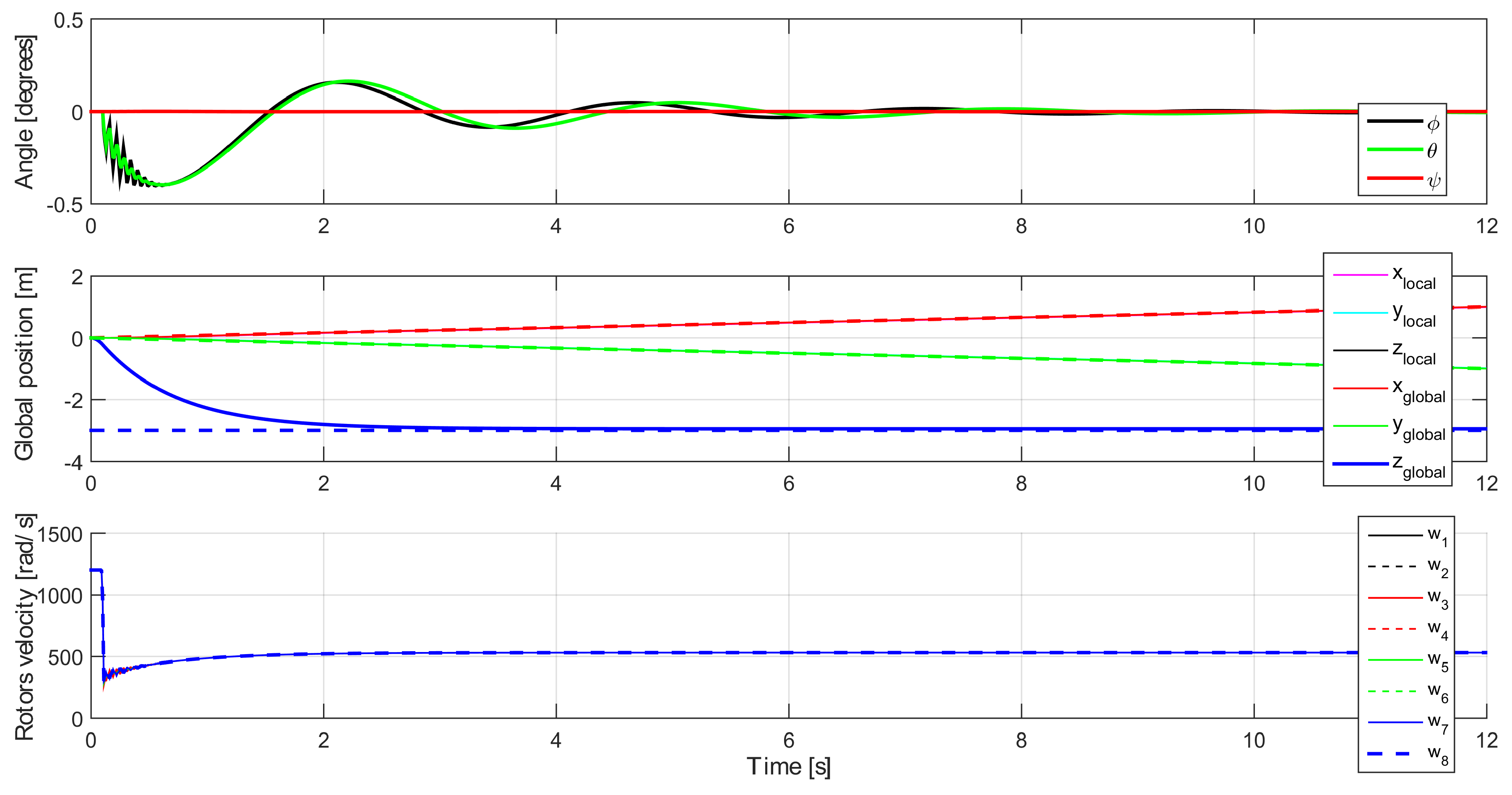
The behaviour of the coaxial quadrotor model within the time horizon equal to 50 s was analyzed. At the moment of beginning, the local reference system coincided with the system of the observer. The aim of the test was to maintain the desired altitude of 3 m at simultaneously linear change of position in the other reference system axis. The behaviour of the inner control loop (angles) and changes in rotational speed of particular propulsion units of the robot were analyzed. It was also assumed that the coaxial quadrotor cannot rotate about the z axis. The rotational speeds of particular propulsion units were limited to 1200 rad / s (equivalent of 11 , 459.16 RPM ).
Figure 8 shows the results obtained in the first 12 s of flight. The applied control system allowed the quadrotor (after about 3 s ) to rise to the fixed altitude with simultaneous adjustment of ϕ and θ angles.

4.3. Experiment No. 2

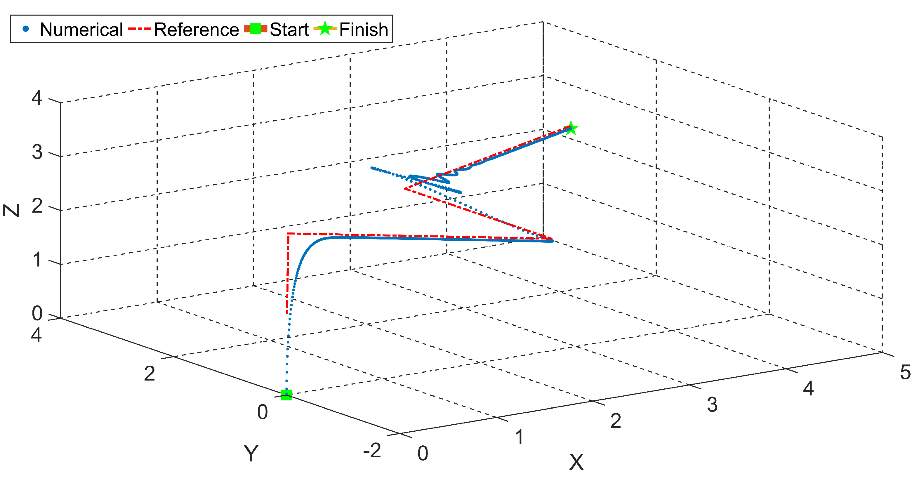
Experiment no. 2 extended the previous test, ie. in the 21 s of flight (at the altitude of 3 m ) a step change of the set position in the Y axis was forced in the opposite direction to the current flight. Furthermore, the rotation of the coaxial quadrotor about the ψ angle was introduced during the movement of the robot relative to the z axis. The experiment results are provided in Figure 9 and Figure 10.
The stated goals of these two tests allowed us to evaluate both the behaviour of a real quadrotor through the implementation of its mathematical model, as well as the effectiveness of control of continuous rotation of the coaxial quadrotor during the change of its position in 3D (without a cascade control system, manual maneuverability by the change of quadrotor’s angles and thrust is a challenge in itself). Experiment results highlight that the rapid changes of rotational speed of particular UAV’s units allow us to effectively compensate the tilt of robot after the change of set position. Naturally, the effectiveness of the control system can be increased (for example, through the selection of a different strategy for controllers tuning or using a different type of controller than the one used for tests).

4.4. Experiment No. 3 (with Real-World Data from the Falcon V5 Flying Robot)

Tests of the proposed coaxial quadrotor model would not be complete without the validation with real, measured data recorded from the Falcon V5 flying robot. The experiment of length of 40 s was performed (see Supplementary Materials). The semi-autonomously controlled Falcon V5 moved to a fixed altitude (2 m ). Then he flew forward about 4–5 m and return to the base point on the set altitude. In the next stage, the UAV was tasked to fly about 4–5 m to the left and return to the base point, ending the attempt with landing near the starting point. In straight flight, the altitude was changed simultaneously, and in flight from side to side—it remained unchanged.
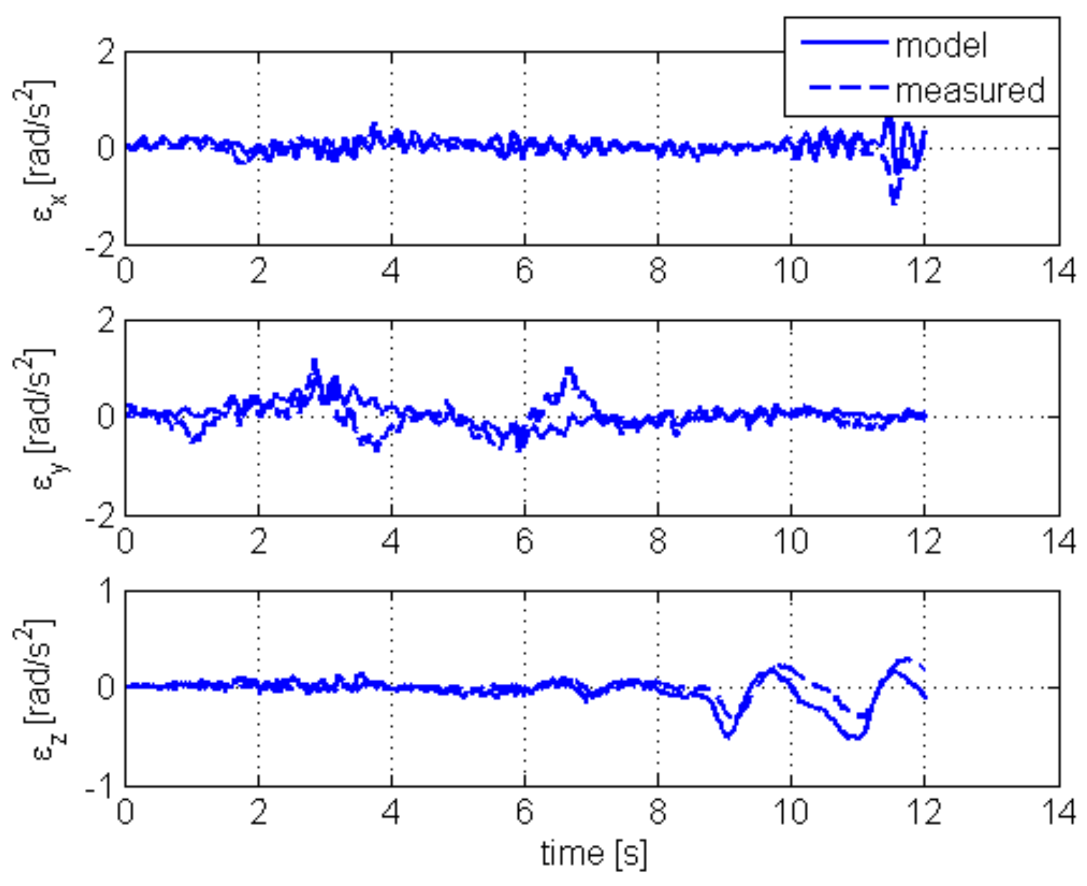
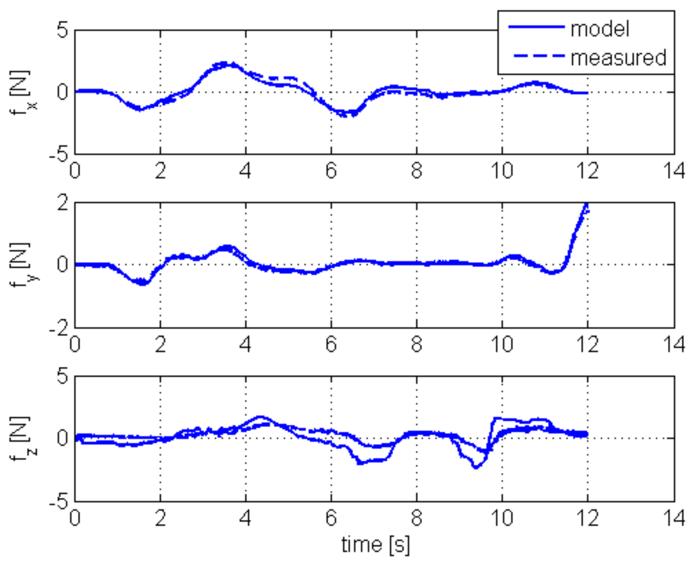
In Figure 11, angular accelerations (in x,y,z EF coordinates) calculated for the Falcon V5 UAV model and real, measured data (i.e., the derivative of measured angular velocity), are shown. Figure 12 presents, respectively, forces (in x , y , z EF coordinates) calculated from the model and measured by the accelerometer (precisely: accelerometer measurements after filtration and subtraction of the force of gravity projected on its axies). It should be remembered that during the hovering (when the force of gravity is equal to the thrust), the accelerometer does not show the state of equilibrium (zero on axes). It returns the value of the force of gravity.
The obtained results are promising, but it should be noted that the UAV model requires continuous modification of rotors thrusts gains [31]. Otherwise one will not be able to obtain precise estimates of model parameters. The experiments conducted by the authors did not cover this estimation issue.

5. Summary

It is said that modeling is the key to a better understanding of the world around us. The more difficult and more complex behavioral aspect is analyzed, the more complex mathematical-physical formulas accompan its description.
From the perspective of efficient control algorithms design, it is necessary to build models that are flexible enough to be compared to one another and to be simplified according to predefined requirements. The model of coaxial quadrotor proposed in this paper fulfills this task as it can be used effectively both to analyze the orientation of the robot in the 3D space and to verify the quality of the estimation algorithms [31], as well as for control design.
The obtained results allowed the authors to plan further research—specifically, on increase of the universality of coaxial quadrotor model. These studies include modeling of the dynamics of drive units mounted in pairs (so far approximated in tests by simple, linear, inertial mathematical models) and research on the effects of aerodynamic behaviour of UAVs during the flight by use of such a solution. Initial trials and results are presented in [41].
The second equally interesting, priority direction of research already begun by the authors is a quantitative investigation the role of small aerodynamic effects (usually neglected are known to be small) on controllers (especially relying only on basic inertial measurements).

Supplementary Materials

Recorded video (Experiment no. 3 with real-world data from the Falcon V5 Flying robot), is available online at https://youtu.be/rvK13uIxkns.

Author Contributions

Conceptualization, W.G. and J.G. (Jarosław Gośliński); methodology, W.G., J.G. (Jarosław Gośliński), J.G. (Jagoda Goślińska), T.E.-F. and J.R.; software, J.G. (Jarosław Gośliński); validation, W.G., J.G. (Jarosław Gośliński), J.G. (Jagoda Goślińska), T.E.-F., J.R.; formal analysis, T.E.-F.; investigation, W.G., J.G. (Jarosław Gośliński); resources, W.G., J.G. (Jarosław Gośliński); data acuration, W.G., J.G. (Jarosław Gośliński); writing—original draft preparation, W.G.; writing—review and editing, W.G., J.G. (Jarosław Gośliński), J.R.; visualization, W.G.; supervision, W.G.; project administration, W.G.; funding acquisition, W.G. All authors have read and agreed to the published version of the manuscript.

Funding

This research was financially supported as a statutory work of Poznan University of Technology (No. 0214/SBAD/0210).

Institutional Review Board Statement

Not applicable.

Informed Consent Statement

Not applicable.

Data Availability Statement

Data available on request due to restrictions.

Acknowledgments

The authors would like to thank Stanislaw Gardecki and Adam Bondyra for their contribution on the experiment configuration.

Conflicts of Interest

The authors declare no conflict of interest.

Abbreviations

The following abbreviations are used in this manuscript:
BLDCBrushless Direct Current Electric Motor
CCWCounter-Clockwise
CFRPCarbon Fiber Reinforced Polymer
CWClockwise
DOFDegree of Freedom
ESCElectronic Speed Controller
IMUInertial Measurement Unit
LQRLinear-Quadratic Regulator
NEDNorth-East-Down
PDProportional–Derivative Controller
PIDProportional–Integral–Derivative Controller
PSOParticle Swarm Optimization
PWMPulse-Width Modulation
UAVUnmanned Aerial Vehicle

Appendix A

Remark no. 1 (Rotation matrix in “3–2–1” sequence)
Assume that w EF , w EF , w EF and w BF . Then:
w = R z T ( ψ ) w ,
w = R y T ( θ ) w ,
w = R x T ( ϕ ) w ,
thus:
w = R z T ( ψ ) R y T ( θ ) R x T ( ϕ ) w ,
w = R x ( ϕ ) R y ( θ ) R z ( ψ ) T w ,
w = R x ( ϕ ) R y ( θ ) R z ( ψ ) w .
Remark no. 2 (Euler rates in “3–2–1” convention)
If the Euler rates vector, given as:
θ ˙ = ϕ ˙ θ ˙ ψ ˙ T
comprises derivatives of Euler angles, and if the consecutive operations in the sequence “3–2–1” provide the transformation:
EF R z T ( ψ ) EF R y T ( θ ) EF R x T ( ϕ ) BF
then, based on vectors parallelism in adjacent coordinate systems, the projections of Euler rates on axes of BF are:
ω ϕ = ϕ ˙ 0 0 T ,
ω θ = R x ( ϕ ) 0 θ ˙ 0 T ,
ω ψ = R x ( ϕ ) R y ( θ ) 0 0 ψ T ,
which is equal to (11).

References

  1. Haddadi, S.-J.; Zarafshan, P. Attitude control of an autonomous octorotor. In Proceedings of the 2014 Second RSI/ISM International Conference on Robotics and Mechatronics (ICRoM), Tehran, Iran, 15–17 October 2014; pp. 540–545. [Google Scholar]
  2. Raharja, G.; Kwangjoon, Y. Design and implementation of coaxial quadrotor for an autonomous outdoor flight. In Proceedings of the 2011 8th International Conference on Ubiquitous Robots and Ambient Intelligence (URAI), Incheon, Korea, 23–26 November 2011; pp. 61–63. [Google Scholar]
  3. Kim, G.; Nguyen, T.; Budiyono, A. Design and Development of a Class of Rotorcraft-based UAV. J. Adv. Robot. Syst. 2013, 131, 1–9. [Google Scholar] [CrossRef] [Green Version]
  4. Bermes, C. Design and Dynamic Modeling of Autonomous Coaxial Micro Helicopters. Ph.D. Thesis, ETH Zurich, Zurich, Switzerland, 2010. [Google Scholar]
  5. Liu, H.; Wang, X.; Zhong, Y. Quaternion-based robust attitude control for uncertain robotic quadrotors. IEEE Trans. Ind. Inform. 2015, 11, 406–415. [Google Scholar] [CrossRef]
  6. Huang, H.; Hoffmann, G.; Waslander, S. Aerodynamics and control of autonomous quadrotor helicopters in aggressive maneuvering. In Proceedings of the 2009 IEEE International Conference on Robotics and Automation, Kobe, Japan, 12–17 May 2009; pp. 3277–3282. [Google Scholar]
  7. Lei, Y.; Bai, Y.; Xu, Z. An experimental investigation on aerodynamic performance of a coaxial rotor system with different rotor spacing and wind speed. Exp. Therm. Fluid Sci. 2013, 44, 779–785. [Google Scholar] [CrossRef]
  8. Sharf, I.; Nahon, M.; Harmat, A. Ground effect experiments and model validation with draganflyer rotorcraft. In Proceedings of the 2014 International Conference on Unmanned Aircraft Systems (ICUAS), Orlando, FL, USA, 27–30 May 2014; pp. 1158–1166. [Google Scholar]
  9. Cho, S.H.; Bhandari, S.; Cheung, K.K.; Tischler, M.B. System Identification and Controller Optimization of a Coaxial Quadrotor UAV in Hover. In Proceedings of the AIAA Scitech 2019 Forum, San Diego, CA, USA, 7–11 January 2019; pp. 1–14. [Google Scholar]
  10. Tsadok, T. Thruster Modeling for Small Unmanned Aerial Vehicles with Coaxial-Rotors. Ph.D. Thesis, McGill University, Montreal, QC, Canada, 2014. [Google Scholar]
  11. Clark, A.; Walker, M. Quadrotor Aerodynamic Test; Technical Report UW 1961; Aeronautical Laboratory, University of Washington: Seattle, WA, USA, 2010. [Google Scholar]
  12. Wei, P.; Yang, Z.; Wang, Q. The design of quadcopter frame based on finite element analysis. In Proceedings of the 3rd International Conference on Mechatronics, Robotics and Automation (ICMRA), Shenzhen, China, 20–21 April 2015; pp. 1353–1356. [Google Scholar]
  13. Zhang, D.; Qi, H.; Wu, T. The quadrotor dynamic modeling and indoor target tracking control method. Math. Probl. Eng. 2014, 1, 1–9. [Google Scholar] [CrossRef] [Green Version]
  14. Kuric, M.; Osmic, N.; Tahirovic, A. Multirotor Aerial Vehicle modeling in Modelica. In Proceedings of the 12th International Modelica Conference, Prague, Czech Republic, 15–17 May 2017; pp. 373–380. [Google Scholar]
  15. Chen, Z.; Peng, Z.; Zhang, F. Attitude control of coaxial tri-rotor UAV based on linear extended state observer. In Proceedings of the 26th Chinese Control and Decision Conference (CCDC), Changsha, China,, 31 May–2 June 2014; pp. 4204–4209. [Google Scholar]
  16. Liu, W.; Huo, X.; Liu, J.; Wang, L. Parameter Identification for a Quadrotor Helicopter Using Multivariable Extremum Seeking Algorithm. Int. J. Control. Autom. Syst. 2018, 16, 1951–1961. [Google Scholar] [CrossRef]
  17. Tofigh, M.A.; Mahjoob, M.J.; Ayati, M. Dynamic modeling and nonlinear tracking control of a novel modified quadrotor. Int. J. Robust Nonlinear Control. 2018, 28, 552–567. [Google Scholar] [CrossRef]
  18. Jeong, H.; Hwang, M.; Jung, H. Mathematical modeling of a multilayered drift-stabilization method for micro-UAVs using inertial navigation unit sensor. J. Appl. Math. 2014, 1, 1–11. [Google Scholar] [CrossRef]
  19. Subudhi, C.S.; Ezhilarasi, D. Modeling and Trajectory Tracking with Cascaded PD Controller for Quadrotor. Procedia Comput. Sci. 2018, 133, 952–959. [Google Scholar] [CrossRef]
  20. Elkholy, H. Dynamic Modeling and Control Techniques for a Quadrotor; IGI Global Publisher: Hershey, PA, USA, 2019. [Google Scholar]
  21. Bouadi, H.; Mora-Camino, F. Modeling and Adaptive Flight Control for Quadrotor Trajectory Tracking. J. Aircr. 2018, 55, 666–681. [Google Scholar] [CrossRef]
  22. Bodo, S.; Lantos, B. Modeling and Control of Outdoor Quadrotor UAVs. In Proceedings of the IEEE 16th International Symposium on Intelligent Systems and Informatics, Subotica, Serbia, 13–15 September 2018; pp. 111–116. [Google Scholar]
  23. Saied, M.; Shraim, H.; Lussier, B.; Fantoni, I.; Francis, C. Local Controllability and Attitude Stabilization of multirotor UAVs: Validation on a coaxial Octorotor. RObotics Auton. Syst. 2017, 91, 128–138. [Google Scholar] [CrossRef] [Green Version]
  24. Gautam, D.; Ha, C. Control of a quadrotor using a smart self-tuning fuzzy PID controller. J. Adv. Robot. Syst. 2013, 10, 1–9. [Google Scholar] [CrossRef]
  25. Kurak, S.; Hodzic, M. Control and Estimation of a Quadcopter Dynamical Model. Period. Eng. Nat. Sci. 2018, 6, 63–75. [Google Scholar] [CrossRef]
  26. Grau, A.; Bolea, Y.; Sanfeliu, A. Quadrotor Multi-model for Control Purposes. Int. Conf. Math. Model. Phys. Sci. 2018, 1141, 1–6. [Google Scholar] [CrossRef]
  27. Lee, H.; Kim, H.J. Trajectory tracking control of multirotors from modelling to experiments: A survey. Int. J. Control. Autom. Syst. 2017, 15, 281–292. [Google Scholar] [CrossRef]
  28. Nascimento, T.P.; Saska, M. Position and attitude control of multi-rotor aerial vehicles: A survey. Annu. Rev. Control 2019, 48, 129–146. [Google Scholar] [CrossRef]
  29. Goslinski, J.; Giernacki, W.; Gardecki, S. An efficient PSO-based method for an identification of a quadrotor model parameters. Adv. Intell. Syst. Comput. 2015, 351, 95–104. [Google Scholar]
  30. Szafranski, G.; Czyba, R.; Blachuta, M. Modeling and identification of electric propulsion system for multirotor unmanned aerial vehicle design. In Proceedings of the 2014 International Conference on Unmanned Aircraft Systems, Orlando, FL, USA, 27–30 May 2014; pp. 470–476. [Google Scholar]
  31. Goslinski, J.; Giernacki, W.; Kasinski, A.; Owczarek, P.; Gardecki, S. A study on coaxial quadrotor model identification and parameter estimation: The improved square root unscented Kalman filter. J. Intell. Robot. Syst. 2019, 95, 491–510. [Google Scholar] [CrossRef] [Green Version]
  32. Njinwoua, B.J.; Wouwer, A.V. Cascade attitude control of a quadcopter in presence of motor asymmetry. Sci. Ifac Pap. 2018, 51, 113–118. [Google Scholar]
  33. Hermand, E.; Nquyen, T.W.; Hosseinzadeh, M.; Garone, E. Constrained Control of UAVs in Geofencing Applications. In Proceedings of the 26th Mediterranean Conference on Control and Automation (MED), Zadar, Croatia, 19–22 June 2018; pp. 217–222. [Google Scholar]
  34. Craig, J.; Walker, M. Introduction to Robotics: Mechanics and Control; Pearson Education International: London, UK, 2005. [Google Scholar]
  35. Goldstein, H.; Poole, C.; Safko, J. Classical Mechanics, 3rd ed.; Addison Wesley: Reading, MA, USA, 2005. [Google Scholar]
  36. Olsson, H.; Astrom, K.; Wit, C.; Gfvert, M.; Lischinsky, P. Friction models and friction compensation. Eur. J. Control 1998, 4, 176–195. [Google Scholar] [CrossRef] [Green Version]
  37. Bangura, M.; Mahony, R. Nonlinear dynamic modeling for high performance control of a quadrotor. In Proceedings of the Australasian Conference on Robotics and Automation, Victoria University of Wellington, Wellington, New Zealand, 3–5 December 2012; pp. 1–9. [Google Scholar]
  38. Mahony, R.; Kumar, V.; Corke, P. Multirotor aerial vehicles: Modeling, estimation and control of quadrotor. IEEE Robot. Autom. Mag. 2012, 19, 20–32. [Google Scholar] [CrossRef]
  39. Leishman, J.G. Principles of Helicopter Aerodynamics; Cambridge Aerospace Series; Cambridge Aerospace: Cambridge, MA, USA, 2002. [Google Scholar]
  40. Bangura, M. Aerodynamics and Control of Quadrotors. Ph.D. Thesis, The Australian National University, Canberra, Australia, 2017. [Google Scholar]
  41. Bondyra, A.; Gardecki, S.; Gasior, P.; Giernacki, W. Performance of coaxial propulsion in design of multi-rotor UAVs. Adv. Intell. Syst. Comput. 2016, 440, 523–531. [Google Scholar]
  42. Kennedy, J.; Eberhart, R. Particle swarm optimization. J. Appl. Math. 1995, 1, 1–11. [Google Scholar]
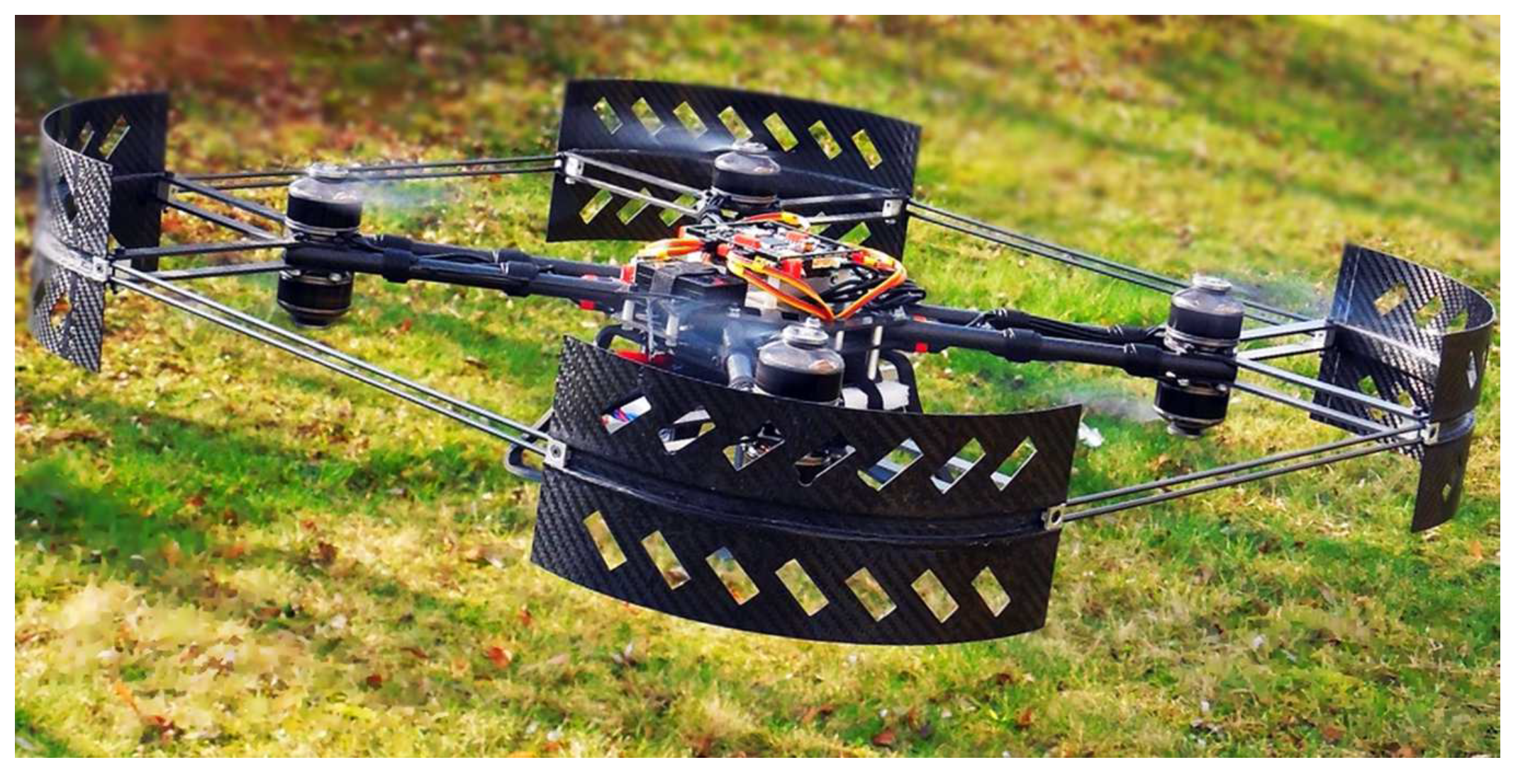
Figure 1. The Falcon V5 coaxial quadrotor developed at the Institute of Robotics and Machine Intelligence of Poznan University of Technology.
Energies 14 01232 g001
Figure 2. North–East–Down (NED) configuration.
Energies 14 01232 g002
Figure 3. Rotation around the axis x,y,z about Roll (a), Pitch (b) and Yaw (c) angle and translations along x (d), y (e), z (f) axis through the increase (+) and/or reduction (−) of rotational speed of coaxial propulsion units (pairs: one above the other).
Energies 14 01232 g003
Figure 4. A block diagram of the coaxial quadrotor control.
Energies 14 01232 g004
Figure 5. “3–2–1” rotations sequence. Note: Four coordinate systems have a common origin. For better graphical presentation they have been shifted.
Energies 14 01232 g005
Figure 6. Falcon V5 (a) 3D model, (b) scheme ( ω : CW/CCW).
Energies 14 01232 g006
Figure 7. Block diagram illustrating the following steps to obtain the unmanned aerial vehicle (UAV) model in control system.
Energies 14 01232 g007
Figure 8. Results of experiment no. 1. From above: Euler’s angles, positions (in X,Y,Z BF and in x,y,z EF coordinates) and rotors velocity for simulated UAV.
Energies 14 01232 g008
Figure 9. Results of experiment no. 2. From above: Euler’s angles, positions (in X,Y,Z BF and in x,y,z EF coordinates) and rotors velocity for simulated UAV.
Energies 14 01232 g009
Figure 10. Reference and recorded flight paths (Exp. no. 2).
Energies 14 01232 g010
Figure 11. Results of experiment no. 3: angular accelerations in x,y,z EF coordinates for Falcon V5 real UAV (measured) and its model.
Energies 14 01232 g011
Figure 12. Results of experiment no. 3: forces in x,y,z EF coordinates for Falcon V5 real UAV (measured) and its model.
Energies 14 01232 g012
Publisher’s Note: MDPI stays neutral with regard to jurisdictional claims in published maps and institutional affiliations.