Article

CTF and FLOCAL Thermal Hydraulics Validations and Verifications within a Multiscale and Multiphysics Software Development

1
School of Engineering, University of Liverpool, Liverpool L69 3GH, UK
2
Institute of Innovation, Helmholtz Zentrum Dresden Rossendorf, 01328 Dresden, Germany
3
EDF Energy, Gloucester GL4 3RS, UK
*
Author to whom correspondence should be addressed.
Energies 2021, 14(5), 1220; https://doi.org/10.3390/en14051220
Submission received: 22 January 2021 / Revised: 15 February 2021 / Accepted: 18 February 2021 / Published: 24 February 2021
(This article belongs to the Special Issue Turbulence and Fluid Mechanics)

Abstract

:
Simulation codes allow one to reduce the high conservativism in nuclear reactor design improving the reliability and sustainability associated with nuclear power. Full-core coupled reactor physics at the rod level are not provided by most simulation codes. This has led in the UK to the development of a multiscale and multiphysics software development focused on LWRS. In terms of the thermal hydraulics, simulation codes suitable for this multiscale and multiphysics software development include the subchannel code CTF and the thermal hydraulics module FLOCAL of the nodal code DYN3D. In this journal article, CTF and FLOCAL thermal hydraulics validations and verifications within the multiscale and multiphysics software development have been performed to evaluate the accuracy and methodology available to obtain thermal hydraulics at the rod level in both simulation codes. These validations and verifications have proved that CTF is a highly accurate subchannel code for thermal hydraulics. In addition, these verifications have proved that CTF provides a wide range of crossflow and turbulent mixing methods, while FLOCAL in general provides the simplified no-crossflow method as the rest of the methods were only tested during its implementation into DYN3D.

1. Introduction

A nuclear renaissance in the UK (United Kingdom) is on the verge of occurring due the reliability and sustainability associated with nuclear power which makes it ideal as an energy source to conform part of the future energy plan of the country. Its reliability depends on its capability to answer the local or national electricity demands by providing the intended output. In addition, its reliability depends on its capability to operate under safety limits by using either active or passive safety systems. Finally, its reliability depends on its capability to avoid nuclear proliferation by minimising the possibilities of theft and terrorism activities. Its sustainability depends on its capability to behave cost effectively by becoming economically competitive when compared to renewable energy sources. In addition, its sustainability depends on its capability to operate under environment friendly standards by using different types of fuel cycles. Finally, its sustainability depends on its capability to evolve by providing alternative technologies.
All these capabilities have been improved in the UK through the different generations of nuclear reactors. Generation I nuclear reactors were developed through the 1950s and 1960s to prove the applicability of nuclear power to provide electricity consisting of the previously used MAGNOX (magnesium oxide gas reactor). Generation II nuclear reactors were developed through the 1970s to improve the reliability and sustainability associated with nuclear power by increasing the production of electricity, including active safety systems, encompassing a closed fuel cycle, and extending the lifespan to 60 years consisting of the currently used AGR (advanced gas reactor) and PWR (pressurised water reactor). Generation III and III+ nuclear reactors were developed in the 1990s to improve the reliability and sustainability associated to nuclear power by enhancing fuel technology and thermal efficiency, adding modular components, including passive safety systems, and extending the lifespan to further than 60 years consisting on the currently-under-construction EPR (European pressurised reactor) and the currently planned SMR (small modular reactor). Generation IV nuclear reactors are being currently developed to improve the reliability and sustainability associated with nuclear power by including full actinide recycling consisting of the envisioned SFR (sodium fast reactor), MSR (molten salt reactor) and HTR (high-temperature reactor).
Nuclear reactor analysis [1] provides the necessary methodology to describe the wide phenomena that occur in nuclear reactors. It is mainly subdivided into neutronics, which analyses power production by solving the neutron transport equation, and into thermal hydraulics, which analyses heat transfer by solving the fluid and solid dynamics equations. No heat transfer in a nuclear reactor occurs unless there is power production, and hence, the neutronics are said to be coupled to the thermal hydraulics. The neutronics can be analysed through different methods ranging from simplified neutron diffusion to full neutron transport. The thermal hydraulics can be analysed through different methods ranging from simplified fluid dynamics to full fluid dynamics.
Simulation codes provide the necessary accuracy to describe the correct phenomena that occur in nuclear reactors. The neutronics of nuclear reactors can be modelled through lattice and transport codes [2,3] with high accuracy at the rod level, with some of them offering homogenisation procedures to provide the necessary neutronics data for use in other simulation codes. The thermal hydraulics of nuclear reactors can be modelled through fluid dynamics codes such as system codes [4,5] with low accuracy at several levels and through subchannel codes [6,7] with high accuracy at the rod level, as well as through CFD (computational fluid dynamics) codes [8,9] with high accuracy at less than the rod level. Coupled reactor physics in nuclear reactors can be modelled through nodal codes [10,11] with variable accuracy at the assembly level, with some of them offering rod power reconstruction to provide improved accuracy at the rod level.
Existing computational constraints during the times when most simulation codes were originally developed led to the inability to provide full-core direct (no reconstruction) coupled reactor physics at the rod level. Rod power reconstruction has always been limited in terms of accuracy and methodology through its inability to encapsulate all the coupled reactor physics phenomena, because it is applied after calculations at the assembly level. The fuel behaviour and nuclear reactor risks analysis is also limited in terms of accuracy and methodology either through their simplification or neglection. The mentioned issues have had an impact on the credibility of simulation codes as safety parameters are based at the assembly level rather than at the rod level, which has resulted in high conservativism in nuclear reactor design.
Full-core direct (no reconstruction) coupled reactor physics at the rod level can be achieved if high accuracy and innovative methodology are considered, which would allow one to redefine safety parameters at the rod level and hence reduce the high conservativism in nuclear reactor design improving the reliability and sustainability associated with nuclear power. The next generation of simulation codes are aimed at providing the mentioned with special emphasis on the world spread LWR (light water reactor). Some of these simulation codes include CASL (consortium for advanced simulation of LWRS) [12,13] and NURESIM (nuclear reactor simulator) [14,15] both of which include high accuracy and innovative methodology to provide full-core coupled reactor physics with several accuracy levels. CASL is too computationally expensive for the UK, while NURESIM does not offer coupled reactor physics at the rod level.
Hence, a multiscale and multiphysics software development between CASL and NURESIM (multiscale multiphysics software development) [16] for LWR has been presented which will include high accuracy and innovative methodology to deliver full-core coupled reactor physics from the assembly level to the rod level. This multiscale and multiphysics software development will acknowledge the requests of the UK by reducing the high conservativism in nuclear reactor design to improve the reliability and sustainability associated with nuclear power; creating a code-coupling environment for data exchange between the simulation codes to provide coupled reactor physics; expanding the simulation codes coupling to the rod level to improve the description of the phenomena that occur in nuclear reactors; and finally, improving the user friendliness of the code coupling environment to reduce user induced mistakes. This multiscale and multiphysics software development will be made computationally inexpensive for the UK by providing coupled reactor physics at the rod level only in certain assemblies and providing coupled reactor physics at the assembly level in all the reactor core.
Several codes will be incorporated into this multiscale and multiphysics software development to include high accuracy and innovative methodology through the following: full neutron-transport codes such as the LTS (Liverpool transport solver) [17] used at the UOL (University of Liverpool) to provide neutronics at the rod level; full fluid-dynamics codes, specially subchannel codes such as CTF (coolant boiling in rod arrays) [18], extensively used for research and commercial purposes to provide thermal hydraulics at the rod level; simplified neutron diffusion and simplified fluid-dynamics nodal codes such as DYN3D (dynamical 3 dimensional) [19], extensively used as well for research and commercial purposes to provide coupled neutronics and thermal hydraulics in general at the assembly level; and finally, fuel-performance codes such as ENIGMA [20], extensively used for commercial purposes to provide thermo mechanics as well as risk assessment codes, such as COSSAN [21], used at the UOL (University of Liverpool) to provide an estimation of nuclear reactor risks. Finally, the mentioned codes will be coupled to provide coupled reactor physics both at the assembly level and the rod level. The mentioned multiscale and multiphysics software development can be observed in Figure 1.
The aim is to create the coupling between the nodal code DYN3D and the subchannel code CTF within the mentioned multiscale and multiphysics software development to provide improved neutronics and thermal hydraulics at the rod level. The first objective into achieving this aim consists of evaluating the accuracy and methodology available to obtain thermal hydraulics at the rod level in both the subchannel code CTF and the thermal-hydraulics module FLOCAL of the nodal code DYN3D, as the accuracy and methodology available to obtain thermal hydraulics at the assembly level in the thermal-hydraulics module FLOCAL of the nodal code DYN3D are known in research. This evaluation will allow one to justify why the subchannel code CTF has been selected to provide high-accuracy thermal hydraulics at the rod level, as well as to justify when FLOCAL rather than CTF should be used to provide improved thermal hydraulics at the rod level. This initial journal article therefore covers the CTF and FLOCAL accuracy and methodology validations and verifications of the thermal hydraulics at the rod level, while the coupling between DYN3D and CTF at the rod level will be covered in future journal articles.
Thermal hydraulics at the rod level are available by default in the subchannel code CTF [22] but not in the thermal hydraulics module FLOCAL of the nodal code DYN3D [23] where thermal hydraulics at the assembly level are in general available. A possibility in the thermal hydraulics module FLOCAL consists of modelling heater-cell-scaled nodes containing one rod instead of assembly-scaled nodes containing many rods to obtain improved thermal hydraulics at the rod level. However, the improved thermal hydraulics at the rod level in the thermal hydraulics module FLOCAL are in general limited in terms of crossflow and mixing methods as opposed to in the high-accuracy thermal hydraulics at the rod level in the subchannel code CTF.
The layout of this journal article is divided into several steps. First, a CTF description has been presented [24,25], and hence general aspects and approach are mentioned to describe the first code used in the accuracy and methodology validations and verifications. Second, a FLOCAL description has been presented [26,27], and hence general aspects and approach are mentioned to describe the second code used in the methodology verification. Third, the tabulation of the specifications used in the CTF accuracy validation and verification has been presented consisting on the PSBT (PWR subchannel and bundle tests) benchmark [28,29,30,31]. Fourth, the tabulation of the specifications used in the FLOCAL and CTF methodology verification has been presented consisting of the FLOCAL developer benchmark. Fifth, the description of the models used in the CTF accuracy validation and verification has been presented according to the specifications. Sixth, the description of the models used in the CTF and FLOCAL methodology verification has been presented according to the specifications.
The results and analysis obtained for the CTF accuracy validation and verification through the PSBT benchmark is comprised by CTF to experimental data comparisons as well as CTF to other codes comparisons. It is divided into the void distribution and the DNB (departure from nucleate boiling) benchmarks. Tests presented include results for the void fraction in a 1 × 1 bundle and results for the void fraction and departure from nucleate boiling in a 5 × 5 bundle with guide tube, although the full benchmark was originally covered in the simulations. The mentioned magnitudes have been chosen as these allow to analyse accuracy in nuclear reactors from a thermal-hydraulics perspective. It can be seen how the mentioned comparisons allow one to show the high accuracy available in CTF compared to other codes.
The results and analysis obtained for the CTF and FLOCAL methodology verification through the FLOCAL developer benchmark are comprised by CTF to FLOCAL comparisons. It is divided into power variation and mass-flux-blockage exercises. Tests presented include results for the void fraction and departure from nucleate boiling in 2 × 1 fuel cells. The mentioned magnitudes have been chosen as these allow one to analyse methodology in nuclear reactors from a thermal-hydraulics perspective. It can be seen how the mentioned comparisons show the innovative methodology available in CTF and in FLOCAL.
Conclusions related to the CTF and FLOCAL accuracy and methodology validations and verifications have been presented to confirm that the first objective in the aim of creating a coupling between CTF and DYN3D within the multiscale and multiphysics software development has been fulfilled by validating and verifying the accuracy of CTF, as well verifying the methodology available in both CTF and FLOCAL. Finally, future work that remains is presented to provide an insight of the next objectives in the aim to create a coupling between CTF and DYN3D within the multiscale and multiphysics software development.

2. Codes Used in the Validations and Verifications

As previously mentioned CTF and FLOCAL are the codes selected as they are extensively used for research and commercial purposes, and hence their main aspects and approach are described in the following subsections.

2.1. CTF Subchannel Code

COBRA-TF [24,25] is a subchannel code created to study both general LWR (square geometry) behaviour and accident-related scenarios. It was coded in FORTRAN in the 80s and 90s by PNL (Pacific Northwest Laboratories), funded by the NRC (Nuclear Regulation Commission) and has since been upgraded by NCU (North Carolina University) and PSU (Pennsylvania State University) to conform CTF. It is widely employed both for steady and transient state analysis due to its capabilities, such as 3D simulation. Most systems, except pressurizers, can be simulated in CTF with these being described through vertical stacks of nodes which represent subchannels. Either rectangular or subchannel coordinates can be used to describe the mentioned system.
A two-fluids (liquid, vapor) and three-flow-fields (liquid film, liquid droplets, and vapor) simulation scheme is employed aided by flow regime/heat-transfer phenomena including two-phase heat, mass and momentum transfer between phases and nodes, entrainment, and quench front tracking. The simulation scheme is set on the nodes where each field is simulated through its own set of mass, momentum, and energy equations. Exceptionally, the liquid and droplet fields remain in thermal equilibrium and therefore share the same energy equation. Finally, the solution to the equations is obtained by employing finite differences and numerical techniques. The SIMPLE (semi-implicit method for pressure-linked equations) algorithm is used to solve the conservation equations which conform a type of homogeneous equilibrium method.
Several settings are necessary to provide results such as the following: stating the time dependence of the simulation in addition to preconditions to carry these out; guessing the flow regime to determine the contact area between phases required to obtain the heat and mass transfer between phases as well as the correct macro and micro nodes closure terms necessary to include the appropriate aggregate physical effects; obtaining the micro node closure terms that link the conservation equations for distinct phases in an equivalent node yielding physical effects between phases, including phase change and entrainment; obtaining the macro node closure terms that link the conservation equations for a same phase in distinct nodes yielding physical effects such as void drift and turbulent mixing; determining the solution to the transport equation associated to the area between phases to acknowledge the mentioned for the droplet field; determining the solution to the conservation equations for the rod to obtain the heat transfer and departure from nucleate boiling necessary to acknowledge the heat conductance; and guessing several solid thermal and mechanical aspects through lists and included models.

2.2. FLOCAL Thermal Hydraulics Module

FLOCAL [26,27] is the thermal hydraulics module of the nodal code DYN3D created to study general LWR-VVER (square and hexagonal geometries) behaviour. It was coded in FORTRAN in the 90s by HZDR (Helmholtz Zentrum Dresden Rossendorf) and has since been upgraded to conform part of DYN3D. It is widely employed both for steady and transient state analysis due to its capabilities, such as 3D simulation. Either a reactor core or a smaller system can be simulated in FLOCAL, with these being described through vertical stacks of nodes which generally represent full channels. Either rectangular or hexagonal coordinates can be used to describe the mentioned system.
A two-fluids (liquid, vapor) simulation scheme is utilized aided by heat-transfer phenomena including: two-phase heat, mass, and momentum transfer between phases. The simulation scheme is set on the nodes where the fluid mixture is simulated through its set of mass, momentum, and energy equations. Exceptionally, the fluid–vapor mass equation is solved apart from the other equations. Finally, the solution to the equations is obtained by employing finite differences and numerical techniques. An implicit-method algorithm is implemented to solve the conservation equations
Several settings are necessary to provide results such as the following: stating the time dependence of the simulation in addition to preconditions to these out; obtaining the constitutive relations that link the conservation equations for distinct phases in the nodes yielding physical effects including phase change; determining the solution to the conservation equations for the rod to obtain the heat transfer and departure from nucleate boiling necessary to acknowledge the heat conductance; and guessing several solid thermal and mechanical aspects through lists and included models.

3. Specifications Used in the Validations and Verifications

As previously mentioned, the CTF accuracy validation and verification have been performed through the replication of the PSBT benchmark. The FLOCAL and CTF methodology verification has been performed through the replication of the FLOCAL developer benchmark. Hence, the specifications used in the mentioned are described in the following subsections.

3.1. PSBT Benchmark

The PSBT benchmark [28,29,30,31] is a validated benchmark for LWR thermal-hydraulics simulation. Experimental data has been obtained by NUPEC at their facilities in Japan using a test rig and several test sections using gamma-ray transmission methods. Code results have been provided by many academic and industrial partners using CFD codes as well as subchannel and system codes. It is divided into the void distribution and the DNB benchmarks. Series of tests carried out include the following: steady-state fractional and full 1 × 1 bundles with uniform axial and radial power distributions, and steady-state 5 × 5 and 6 × 6 bundles with either uniform or cosine axial power distributions and variable radial power distributions, as well as different spacer-grids arrangements and possibility of a central guide tube. The PSBT benchmark includes a wide range of accuracy tests with different outlet pressures, powers, mass fluxes, and inlet temperatures. Only the data for certain test series has been presented, such as test series S1, which corresponds to the full 1 × 1 bundle of the void distribution benchmark, and test series B7 and A8, which correspond to the 5 × 5 with guide-tube bundles of the void distribution and DNB benchmarks.
Specifications include the geometry, materials, spacer grids, power distributions, and initial and boundary conditions. The geometry is described for the 1 × 1 and 5 × 5 bundles as observed in Table 1:
The materials are described for all the bundles as observed in Table 2:
Spacer grids can be any of 3 types including nonmixing vane, mixing vane, and simple, which are represented using pressure-loss coefficients stated for the 5 × 5 bundle in Table 3:
The power distributions are described for the 1 × 1 and 5 × 5 bundles as observed in Table 4:
The initial and boundary conditions for each test are described first for Test Series S1 of the void distribution benchmark, then for Test Series B7 of the void distribution benchmark, and finally for Test Series A8 of the DNB benchmark, as observed in Table 5:

3.2. FLOCAL Developer Benchmark

The FLOCAL developer benchmark is a proposed benchmark for LWR thermal-hydraulics simulation. Code results have been provided by the FLOCAL developer. It is divided into power variation and mass-flux-blockage exercises. Tests carried out include steady-state 2 × 1 heater cells with uniform axial power distribution and variable radial power distribution as well as possibility of local blockage. The FLOCAL developer benchmark includes two methodology tests with different power but same outlet pressures, mass fluxes, and inlet temperatures. All the data for the tests has been presented.
Specifications include the geometry, power distributions and initial and boundary conditions. The geometry is described the two heater cells as observed in Table 6:
The local blockage is represented using a pressure-loss coefficient stated for the mass-flux-blockage exercise in Table 7:
The power distributions are described first for the power variation and then the mass-flux-blockage exercises as observed in Table 8:
The initial and boundary conditions first for the power variation and then the mass-flux-blockage exercises are described as observed in Table 9:

4. Models Used in the Validations and Verifications

As previously mentioned, the CTF accuracy validation and verification have been performed through the replication of the PSBT benchmark. The FLOCAL and CTF methodology verification has been performed through the replication of the FLOCAL developer benchmark. Hence, the models used in the mentioned are described in the following subsections.

4.1. PSBT Benchmark

In CTF, the models comprise in the 1 × 1 bundle one subchannel containing one heater rod while in the 5 × 5 bundle 36 subchannels (subchannel-cantered system) linked by 60 gaps between them containing 24 heater rods and one guide tube. These have been incorporated into one axial section conformed in the 1 × 1 bundle by 30 uniform axial node layers while conformed in the 5 × 5 bundle by 36 non-uniform axial node layers in the case of the void distribution benchmark or 70 non-uniform axial node layers in the case of the DNB benchmark conditioned in any case by the spacer-grid locations. No time dependence has been included to reach thermodynamical equilibrium (steady state). The CTF heater rod and subchannel-centred system designs can be observed in Figure 2.
In all the bundles, Thom’s correlation [32] has been employed to simulate nucleate boiling as it remains valid at higher pressures than Chen’s correlation. In the 5 × 5 bundle, in the case of the DNB benchmark, the W-3 correlation [33,34] has been employed to simulate departure from nucleate boiling it being typically used to study LWR. In the 5 × 5 bundle, a constant single-phase mixing coefficient with a value of 0.05 and a two-phase multiplier according to Beus with a value of 5.0 as well as an equilibrium weighting void drift factor with a value of 1.4 [35] have been employed to simulate turbulent mixing and void drift being typically used to study LWR. In all the bundles the original CTF model has been employed to simulate entrainment and deposition to include liquid droplets fluid phenomena. In all the bundles, McAdams two-phase multiplier correlation [36] has been employed to simulate heater-rod friction pressure losses typically being used to study LWR. In the 5 × 5 bundle several coefficients with a value of 0.5 have been employed to simulate velocity head losses friction pressure losses between heater rods as well as wall friction pressure losses between heater rods and walls. In addition, in the 5 × 5 bundle coefficients with values according to the spacer-grids specifications have been employed to simulate form pressure losses in the corresponding axial node layers. In all the bundles, the Krylov solver has been used to obtain a solution to the pressure equation with it being more effective than Gaussian elimination.

4.2. FLOCAL Developer Benchmark

In CTF and FLOCAL, the models comprise two heater cells linked by one gap between them in the case of the former containing two heater rods. These have been incorporated into one axial section conformed by 10 uniform axial node layers. No time dependence has been included to reach thermodynamical equilibrium (steady state). The heater-rod-centred system design in both CTF and FLOCAL can be observed in Figure 3
Thom’s correlation [32] has been employed to simulate nucleate boiling in CTF as it remains valid at higher pressures than Chen’s correlation, while Rassokhin and Borishaskji [37] correlation has been employed to simulate nucleate boiling in FLOCAL, with it being the existing one. The W-3 correlation [33,34] has been employed to simulate departure from nucleate boiling in CTF, with it being typically used to study LWR, while the Bezrukov and Astakhov correlation [38] has been employed to simulate departure from nucleate boiling in FLOCAL, with it being one of the several available. Different methods later mentioned have been implemented to simulate both crossflow and turbulent mixing in both CTF and FLOCAL. The original CTF model has been employed to simulate entrainment and deposition to include liquid-droplets fluid phenomena, while no model has been employed in FLOCAL, as it does not allow liquid droplets. McAdams two-phase multiplier correlation [36] has been employed to simulate heater-rod friction pressure losses in CTF it being typically used to study LWR while Filonenko’s and Osmachkin’s one- and two-phase multiplier correlation [39] has been employed to simulate heater-rod friction pressure losses in FLOCAL, with it being the existing one. A single coefficient with a value of 0.5 has been employed to simulate velocity head friction pressure losses between heater rods in CTF, while no coefficient has been employed to simulate velocity head friction pressure losses between heater rods in FLOCAL. A coefficient with a value according to the specifications has been employed to simulate the local blockage in the mass-flux-blockage exercise as a pseudospacer-grid-form pressure loss in the corresponding axial node layer in both CTF and FLOCAL. The Krylov solver has been used to obtain a solution to the pressure equation in CTF, with it being more effective than Gaussian elimination, while Gaussian elimination has been used to obtain a solution to the pressure equation in FLOCAL, with it being the existing one.
Crossflow and turbulent mixing methods simulated in CTF include the following: The no-crossflow method, where mass, momentum, and energy equations for each channel are solved without allowing mass, momentum, and energy transfer between the heater cells. The crossflow method where mass, momentum, and energy equations for each channel are solved allowing mass, momentum, and energy transfer between the heater cells. The Rogers and Rosehart mixing method where mass, momentum, and energy equations for each channel are solved allowing mass, momentum, and energy transfer as well as void drift and turbulent mixing through an empirical-correlation-calculated single-phase mixing coefficient and a two-phase multiplier with a value of 5.0 as well as an equilibrium weighting void drift factor with a value of 1.4 [40]. The constant-mixing method where mass, momentum, and energy equations for each channel are solved allowing mass, momentum, and energy transfer as well as void drift and turbulent mixing through a constant single-phase mixing coefficient with a value of 0.05 and a two-phase multiplier with a value of 5.0 as well as an equilibrium weighting void drift factor with a value of 1.4.
Crossflow methods simulated in FLOCAL include the following: The no-crossflow method, where mass, momentum and energy equations for each channel are solved without allowing mass, momentum, and energy transfer between the heater cells. The partial-crossflow method where mass, momentum, and energy equations for each channel are solved allowing only mass and momentum transfer between the heater cells. The crossflow method where mass, momentum, and energy equations for each channel are solved allowing mass, momentum, and energy transfer between the heater cells.

5. Results and Analysis

Considering the thermal-hydraulics results obtained with CTF through the replication of the PSBT benchmark [28,29,30,31], CTF to experimental data as well as CTF to other codes results comparisons within the accuracy validation and verification in the steady state are presented for the void fraction as well as the departure from nucleate boiling. Considering the thermal hydraulics results obtained with FLOCAL and CTF through the replication of the FLOCAL developer benchmark. CTF to FLOCAL comparisons within the methodology verification in the steady state are presented for the void fraction as well as for the departure from nucleate boiling.

5.1. PSBT Benchmark

Code to experimental accuracy comparisons within the steady-state void distribution benchmark for the single subchannel (Test Series S1) are presented for the void fraction, while the density and equilibrium quality are presented in Appendix A. Experimental data available consists of a gamma-ray transmission method composed both by CT (narrow gamma beam) as well as chordal (wide gamma beam) measurements with the setup being contained in Appendix A. In both cases, density values were measured and later converted to void fraction values. A relationship between both measurements was then derived to determine the corrected average void fraction value in the subchannel. Void fraction values are presented for the single subchannel at a single location (1.4 m). Linear fitting with interception at the origin has been performed to show similarities and differences between CTF and the experimental values as observed in Figure 4.
Differences between the experimental and CTF void fraction values at the mentioned axial locations are small with no tendency in the estimation of the values. Several reasons were found to cause the observed differences between the CTF and the experimental data: The gamma-ray transmission method used underestimates the void fraction as these experimental measurements were taken at the centres of subchannels instead of near the heated surfaces where most of the void fraction occurs under general LWR behaviour. The nucleate boiling model used affects the void fraction as it may respond differently to the different initial and boundary conditions.
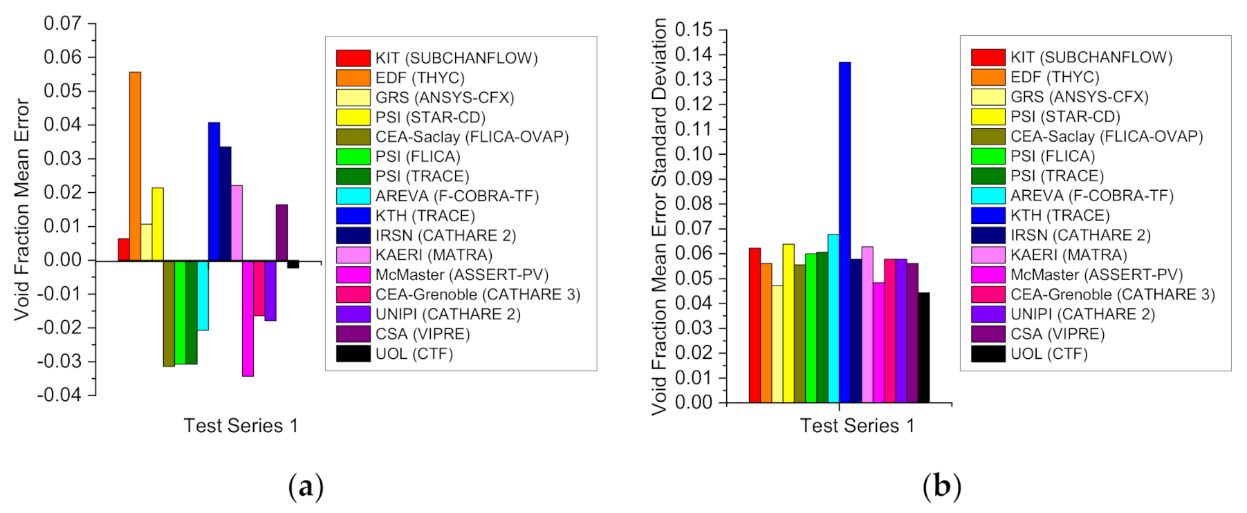
Code to code accuracy comparisons within the steady-state void distribution benchmark for the single subchannel (Test Series S1) are presented only for the void fraction. Code results have been provided by 20 academic and industrial partners including porous media codes (THYC), CFD codes (ANSYS, NEPTUNE…), subchannel codes (VIPRE, SUBCHANFLOW…), and system codes (TRACE, CATHARE…) results with a full list of codes being contained in Appendix A. Void fraction values for each code are presented for the single subchannel at a single axial location (1.4 m). Errors and standard deviations values are calculated to show similarities and differences between CTF and the other codes as observed in Figure 5 and given by Equation (4).
Δ x ¯ = t = 1 M Δ x t N σ = ± t = 1 M Δ x t Δ x ¯ 2 M 1     w h e r e     Δ x t = x t   c o d e x t   e x p
where x t   c o d e , x t   e x p describe either an experimental or code value per test and per datum of any magnitude. Δ x t describes the difference between the code and experimental values for a certain parameter in a test within a series. Δ x ¯ describes the average difference between tests within a series.
Differences between most system codes and CTF void fraction values at the single location are large with most system codes showing larger mean errors and standard deviations compared to CTF. Differences between most subchannel codes and CTF at the single location are variable with some subchannel codes showing larger mean errors and standard deviations than CTF, and others similar mean errors and standard deviations compared to CTF. Differences between CFD/porous media codes and CTF at the single axial location are large with most CFD/porous media codes showing larger mean errors and standard deviations compared to CTF. Most of the CFD/porous media codes as well as system codes show overestimation of the values, while most of the subchannel codes show underestimation of the values. Several reasons were found to cause the observed differences between the CTF and other codes results: System codes tend to offer lower accuracy compared to subchannel codes and hence consume less time to achieve results. CFD/porous media codes however tend to offer in general higher accuracy compared to subchannel codes and hence consume more time to achieve results.
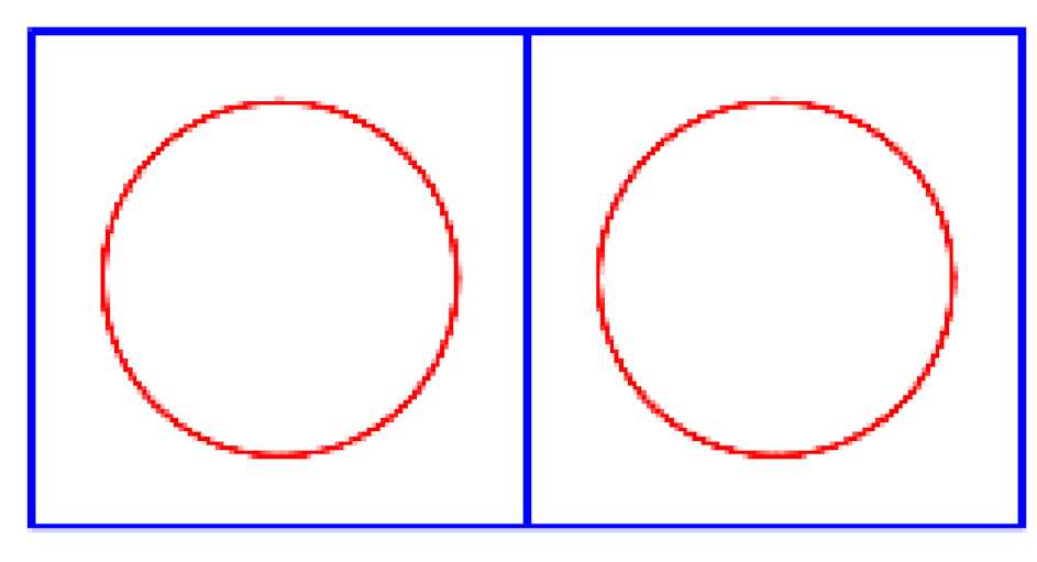
Codes for experimental accuracy comparisons within the steady-state void distribution benchmark for the 5 × 5 bundle with guide tube (Test Series B7) are presented for the void fraction with the equilibrium quality being presented in Appendix A. Experimental data available consists of a gamma-ray transmission method composed both by CT (narrow gamma multibeam) as well as chordal (wide gamma multibeam) measurements with the setup being contained in Appendix A. In both cases, density values were measured and later converted to void fraction values. A relationship between both measurements was then derived to determine the corrected average void fraction value only in the central subchannels of the 5 × 5 bundle. Void fraction values are presented for the central subchannels at three different axial locations including a lower region (2.216 m) and an intermediate region (2.669 m), as well as an upper region (3.177 m). Linear fitting with interception at the origin has been performed to show similarities and differences between CTF and the experimental values as observed in Figure 6.
Differences between the experimental and CTF void fraction values at the three axial locations are small with slight overestimation of the lower region and intermediate region values and slight underestimation of the upper region values. Several reasons were found to cause the observed differences between the CTF and the experimental data: The gamma-ray transmission method used underestimates the void fraction as these experimental measurements were taken at the centres of subchannels instead of near the heated surfaces where most of the void fraction occurs under general LWR behaviour. The nucleate boiling model used affects the void fraction as it may respond differently to the different initial and boundary conditions. The crossflow and mixing models used affect the void fraction codes which include crossflow as well as turbulent mixing models achieve the best correlation between experimental measurements and code results.
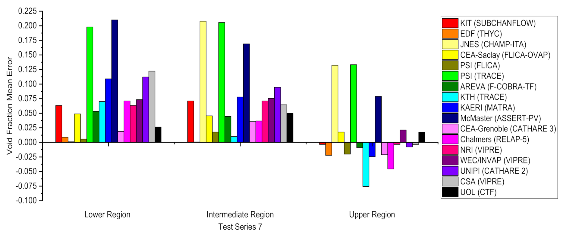
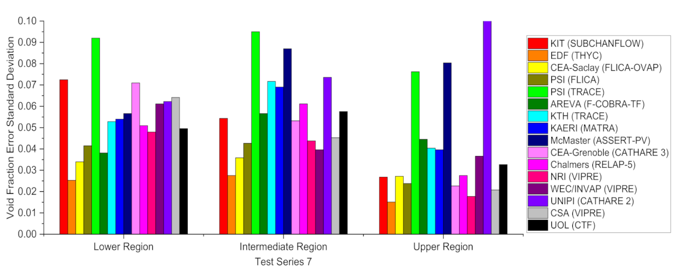
Code-to-code accuracy comparisons within the steady-state void distribution benchmark for the 5 × 5 bundle with guide tube (Test Series B7) are presented for the void fraction. Code results have been provided by 16 academic and industrial partners including porous-media codes (THYC), subchannel codes (MATRA, SUBCHANFLOW…), and system codes (TRACE, CATHARE…) results with a full list of the participants and code types being contained in Appendix A. Void fraction values for each code are presented for the central subchannels at three different axial locations including a lower region (2.216 m), an intermediate region (2.669 m), and an upper region (3.177 m). Errors and standard deviations values are calculated to show similarities and differences between CTF and the other codes as observed in Figure 7 and Figure 8 and given by Equation (4).
Differences between most system codes and CTF void fraction values at the 3 axial locations are large, with most system codes showing larger mean errors and standard deviations compared to CTF. Differences between most subchannel codes and CTF at the three axial locations are variable, with some subchannel codes showing larger mean errors and standard deviations compared to CTF, and others, similar mean errors and standard deviations compared to CTF. Differences between the porous-media code and CTF at the three axial locations are similar, with the mentioned one showing smaller mean errors and standard deviations compared to CTF. Most of the codes show overestimation of the lower region and intermediate region values as well as underestimation of the higher region values. Several reasons were found to cause the observed differences between the CTF and other codes results: System codes tend to offer lower accuracy compared to subchannel codes and hence consume less time to achieve results. CFD/porous-media codes however tend to offer in general higher accuracy compared to subchannel codes and hence consume more time to achieve results.
Code-to-experimental accuracy comparisons within the steady state DNB benchmark for the 5 × 5 bundle with guide tube (Test Series A8) are presented for the departure from nucleate boiling. Experimental data available consists of a thermocouples method composed of measurements at several locations with the setup being contained in Appendix A. The wall temperature was measured where a rise of more than 11 C confirmed departure from nucleate boiling with the critical heat flux being defined by the power at the step prior to this wall temperature rise measurement. Critical powers values are presented for the rods at the first occurrence height. Linear fitting with interception at the origin has been performed to show the similarities and differences between CTF and the experimental values, as observed in Figure 9.
Differences between the experimental and CTF critical power values at the first occurrence height are low with slight overestimation of the values. Several reasons were found to cause the observed differences between the CTF and the experimental data: The thermocouples method used overestimates the departure from nucleate boiling as detection can be delayed due to the discrete number of measurement points, and the critical heat-flux correlation used affects the departure from nucleate boiling as many different correlations are available which offer different code results.
Code-to-code accuracy comparisons within the steady state DNB benchmark for the 5 × 5 bundle with guide tube (Test Series A8) are presented for the departure from nucleate boiling. Code results have been provided by 10 academic and industrial partners including porous-media codes (THYC), subchannel codes (MATRA, SUBCHANFLOW…), and system codes (TRACE, CATHARE…) results with a full list of the participants and code types being contained in Appendix A. The first occurrence height for each code is presented for the corresponding heater rod as observed in Figure 10.
Differences between the system codes and CTF departure from nucleate-boiling first-occurrence height values are small with the mentioned two showing similar values compared to CTF. Differences between most subchannel codes and CTF departure from nucleate-boiling first-occurrence height values are variable with some subchannel codes showing larger values compared to CTF and others similar values compared to CTF. Differences between the porous-media code and CTF departure from nucleate-boiling first-occurrence height values are large with the mentioned one showing larger values compared to CTF. Several reasons were found to cause the observed differences between the CTF and other codes results: System codes tend to offer lower accuracy compared to subchannel codes and hence consume less time to achieve results. CFD/porous-media codes however tend to offer in general higher accuracy compared to subchannel codes and hence consume more time to achieve results.

5.2. FLOCAL Developer Benchmark

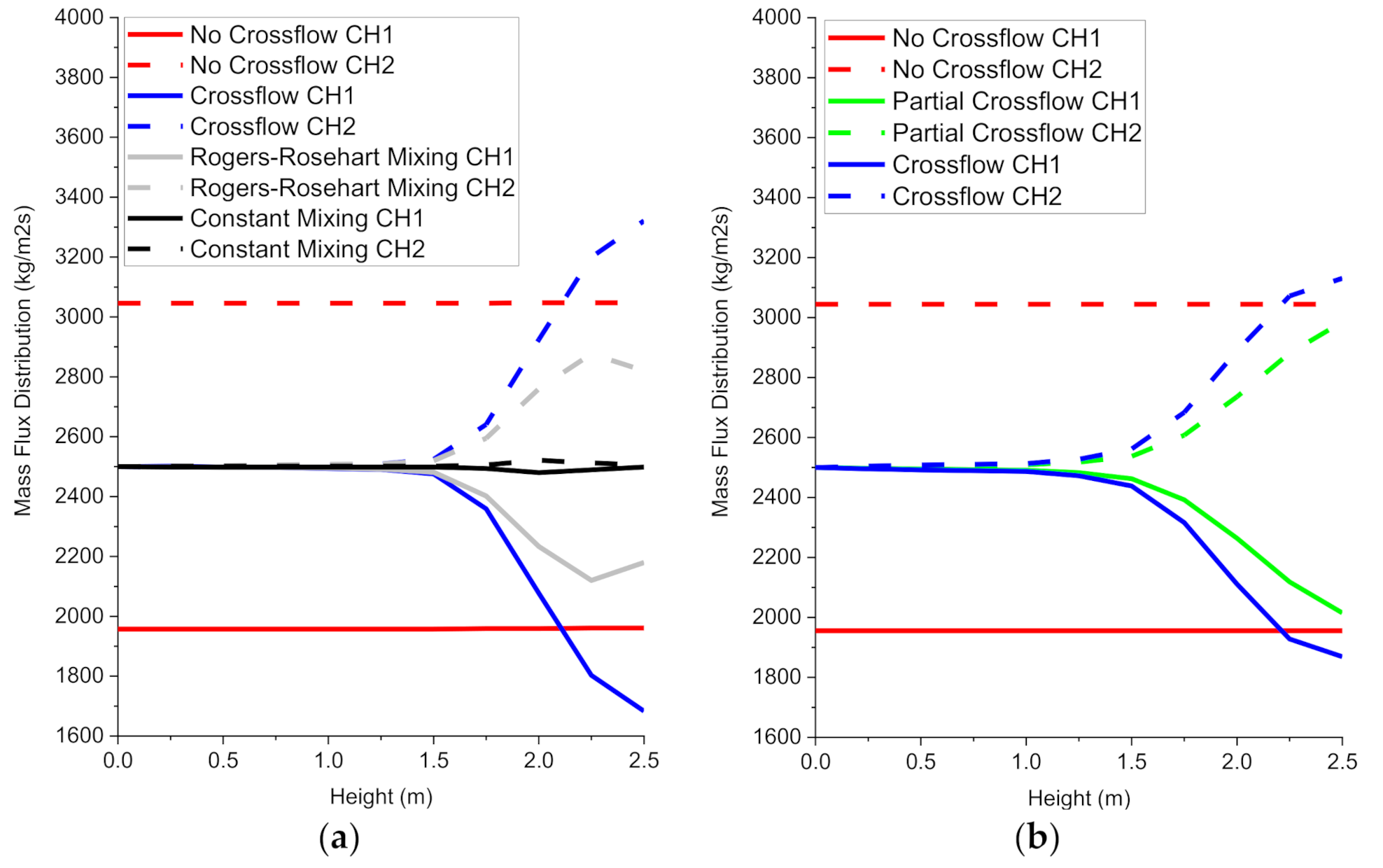
CTF to FLOCAL method comparisons within the power variation exercise for the 2 × 1 heater cells are presented for the void fraction and departure from nucleate boiling with the mass flux and coolant temperature being presented for the power variation and the local mass-flux blockage exercises in Appendix B. Code results have been provided by the FLOCAL developer. Void fraction distributions are presented for the two heater cells to show similarities and differences in the methods available in both CTF and FLOCAL as observed in Figure 11.
The void fraction distribution in CTF and FLOCAL is determined through the fluid density, fluid velocity, and fluid enthalpy distributions which are obtained through the solution to the mass, momentum, and energy equations. No value occurs in any method in both CTF and FLOCAL until the shift from single-phase heat transfer to nucleate-boiling heat transfer which occurs once the wall temperature surpasses the fluid saturation temperature.
In both CTF and FLOCAL, a void fraction distribution rise under nucleate-boiling heat transfer is observed in all the methods. The void fraction distribution in heater cell 1 increases more due its high power resulting on lower fluid densities, higher vapor, and lower liquid velocities, as well as higher fluid enthalpies when compared to heater cell 2. The void fraction distribution in heater cell 2 increases less due its low power resulting on higher fluid densities, lower vapor, and higher liquid velocities as well as lower fluid enthalpies when compared to heater cell 1.
In both CTF and FLOCAL, a higher void fraction distribution increase under nucleate-boiling heat transfer is observed in the no-crossflow method compared to the crossflow method. This occurs due to the exclusion in the conservation equations of mass, momentum, and energy transfer between heater cells. This results in lower fluid densities, higher vapor, and lower liquid velocities as well as higher fluid enthalpies.
In CTF, a higher void fraction distribution increase under nucleate-boiling heat transfer is observed in the crossflow method as opposed to in the Rogers and Rosehart and the constant mixing methods. This occurs due to the exclusion in the conservation equations of turbulent mixing and void drift between heater cells. This results in lower fluid densities, higher vapor, and lower liquid velocities as well as higher fluid enthalpies. In CTF, equal void fraction distribution increase under nucleate-boiling heat transfer is observed in the constant mixing method as opposed to in the Rogers and Rosehart mixing method. This occurs due to the high user specified single mixing coefficient in the case of the former compared to the empirical-correlation-calculated single-mixing coefficient in the case of the latter. This results in equal fluid densities, fluid velocities, and fluid enthalpies between heater cells.
In FLOCAL, an almost equal void fraction distribution increase under nucleate-boiling heat transfer is observed in both the partial crossflow and crossflow methods. This occurs due to the minor contribution of energy transfer in the conservation equations between heater cells. This results in almost equal fluid densities, fluid velocities, and fluid enthalpies.
Between CTF and FLOCAL, only the void fraction distributions in the crossflow and the no-crossflow methods can be compared as the rest are not present in both codes. The crossflow method differs between both codes due to different nucleate-boiling correlations as observed through the delayed onsets of the void fraction distribution in CTF as opposed to in FLOCAL. The no-crossflow method remains identical between codes due to the exclusion of all fluid phenomena occurring between heater cells.
Departure from nucleate boiling ratio distributions is presented for the two subchannels to show similarities and differences in the methods available in both CTF and FLOCAL as observed in Figure 12.
The departure from nucleate-boiling ratio distribution in CTF and FLOCAL is determined through the power distribution and the critical-heat-flux correlation, where the former is initially provided while the latter is obtained through an empirical correlation. No critical value occurs in any method both CTF and FLOCAL as the heat flux does not surpass the critical heat flux.
In both CTF and FLOCAL, a departure from nucleate-boiling ratio distribution decrease under all heat transfer regimes is observed in all the methods. The departure from nucleate-boiling ratio distribution in heater cell 1 decreases more due to its high power, low mass flux, and high pressure drop resulting in lower critical heat fluxes when compared to heater cell 2. The departure from nucleate-boiling ratio distribution in heater cell 2 decreases less due to its low power, high mass flux, and low pressure drop resulting on higher critical heat fluxes when compared to heater cell 1.
In both CTF and FLOCAL, a larger departure from nucleate-boiling ratio distribution decrease under all heat-transfer regimes is observed in the no-crossflow method compared to the crossflow method. This occurs due to the influence on the critical-heat-flux correlation of the absence in the conservation equations of mass, momentum, and energy transfer between heater cells via the mass-flux distributions and pressure drops. This results in lower critical-heat fluxes.
In CTF, a milder departure from nucleate-boiling ratio distribution decrease under all heat-transfer regimes is observed in the crossflow method as opposed to in the Rogers and Rosehart and the constant mixing methods. This occurs due to the influence on the critical-heat-flux correlation of the exclusion in the conservation equations of turbulent mixing and void drift between heater cells via the mass-flux distributions and pressure drops. This results in mildly lower critical-heat fluxes. In CTF, a more equal departure from nucleate-boiling ratio distribution decrease is observed in the constant mixing method as opposed to in the Rogers and Rosehart mixing method. This occurs due to the influence on the critical heat-flux correlation of the high user-specified single mixing coefficient in the case of the former compared to the empirical-correlation-calculated single mixing coefficient in the case of the latter via the mass-flux distributions and pressure drops. This results in more equal critical heat fluxes in both heater cells.
In FLOCAL, an almost equal departure from nucleate-boiling ratio distribution decrease rise under all heat-transfer regimes is observed in both the partial crossflow and crossflow methods. This occurs due to the minor influence on the critical heat-flux correlation of energy transfer in the conservation equations between heater cells. This results in less different critical heat fluxes between heater cells.
Between CTF and FLOCAL, only the departure from nucleate-boiling ratio distributions in the crossflow and the no-crossflow methods can be compared as the rest are not present in both codes. The crossflow method and no-crossflow method differ between both codes due to different critical heat-flux correlations as observed through the larger separation between the departure from nucleate-boiling distributions in CTF as opposed to in FLOCAL.

6. Conclusions

In terms of thermal hydraulics, the first objective in the aim of creating a coupling between CTF and DYN3D within the multiscale and multiphysics software development has been fulfilled by validating and verifying the accuracy in CTF and the methodology available in both CTF and FLOCAL.
Considering the CTF accuracy validation and verification performed through the replication of the PSBT benchmark. CTF provides accurate void fraction and critical power values with no significant tendency overall in the estimation when compared to the experimental data. The observed differences between the CTF results and the experimental data are due to reasons such as the gamma-ray transmission method as well as the nucleate-boiling model. The observed differences between the CTF results and the experimental data in the 5 × 5 bundle are also due to reasons such as the crossflow and mixing models as well as the thermocouples method and the critical heat-flux correlation. CTF provides small void fraction mean error and standard deviation values as well as accurate departure from nucleate-boiling first occurrence height values when compared to other codes results. The observed differences between the CTF results and the other codes results are due to reasons such as the nature of the codes.
Considering the CTF and FLOCAL methodology verification performed through the replication of the FLOCAL developer benchmark. CTF and FLOCAL provide a wide range of methods for the void fraction and departure from nucleate-boiling ratio distributions. The observed differences in the CTF and FLOCAL results are due to reasons such as the exclusion in the conservation equations of mass, momentum, and energy transfer between heater cells, as well as the exclusion of different turbulent mixing and void drift between heater cells. The observed differences between the comparable CTF and FLOCAL results are due to reasons such as the different nucleate boiling and critical heat-flux correlations.
In general, CTF is a highly accurate code when compared to other codes which are less accurate or consume more time to achieve results. Therefore, CTF will be used to provide thermal hydraulics at the rod level within the multiscale and multiphysics software development. In general, CTF provides a wide range of crossflow and turbulent mixing methods when compared to FLOCAL where only the no-crossflow method is available. Therefore, CTF will be used to provide thermal hydraulics at the rod level in cases with more heterogeneous power distributions, while FLOCAL will be used to provide thermal hydraulics at both the assembly and rod levels in cases with more homogeneous power distributions.

7. Future Work

As mentioned before, the next objective in the aim of creating a coupling between the subchannel code CTF and the nodal code DYN3D within the multiscale and multiphysics software development consists of creating the initial stage in the coupling by allowing the exchange of power distributions from DYN3D to CTF to partially fulfil the connection between the CTF subchannel code block and the DYN3D nodal code block within the mentioned multiscale and multiphysics software development. Finally, the last objective in the aim of creating a coupling between the subchannel code CTF and the nodal code DYN3D coupling within multiscale and multiphysics software development will consist of creating the last stage in the coupling by not only allowing the exchange of power distributions from DYN3D to CTF, as well as the exchange of all the thermal-hydraulics distributions from CTF into the code coupling environment.

8. Nomenclature

The acronyms and symbols in the overall text have an associated meaning given in Table 10 and Table 11.

Author Contributions

S.D. as the main author have written this article including the introduction, codes used in the validations and verifications, specifications and models used in the validations and verifications, results an analysis, conclusions, and future work. U.R. as the next author has provided FLOCAL as a result of him being the developer and has suggested the data used in the FLOCAL developer benchmark. D.L. as the next author has introduced the multiscale and multiphysics software development. B.M. and A.L. as the next authors and academic supervisors have provided help from theoretical and practical perspectives. P.B. as the next author and industrial supervisor has suggested the data used in the PSBT benchmark. A.D., S.A., and V.R. as the last authors and advisors have provided help from theoretical and practical perspectivesAll authors have read and agreed to the published version of the manuscript.

Funding

This research was funded by the EPSRC, EDF, and the UOL through the funding of the EPSRC grant “Innovative LWR Simulation Tool for the Nuclear Renaissance in the UK”, EPSRC grant number EP/R005850/1.

Institutional Review Board Statement

Not applicable.

Data Availability Statement

See the References.

Conflicts of Interest

The authors declare no conflict of interest. The funders had no role in the design of the study; in the collection, analyses, or interpretation of data; in the writing of the manuscript, or in the decision to publish the results.

Appendix A. PSBT Benchmark

The gamma-ray transmission method used to obtain experimental data composed both by CT (narrow gamma beam) as well as chordal (wide gamma beam) measurements of the fluid density can be observed in Figure A1 and Figure A2.
Figure A1. Gamma-ray transmission method (subchannel).
Energies 14 01220 g0a1
Figure A2. Gamma-ray transmission method (bundle).
Energies 14 01220 g0a2
The system, subchannel, and CFD codes used to obtain other code results classified according to their associated participant and type in Table A1.
Table A1. Academic and industrial partners codes.
ParticipantCodeType
ANSYSANSYSCFD
GRSANSYS-CFXCFD
HZDRANSYS-CFXCFD
EDFNEPTUNECFD
ANLSTAR-CDCFD
PSISTAR-CDCFD
EDFTHYCPorous Media
JNESCHAMP-ITASubchannel
PSIFLICASubchannel
CEA-SaclayFLICA-OVAPSubchannel
McMasterASSERT-PVSubchannel
KAERIMATRASubchannel
NRIVIPRESubchannel
WEC/INVAPVIPRESubchannel
CSAVIPRESubchannel
KITSUBCHANFLOWSubchannel
ArevaF-COBRA-TFSubchannel
UOLCTFSubchannel
PSITRACESystem
KTHTRACESystem
UNIPICATHARE-2System
IRSNCATHARE-2System
CEA-GrenobleCATHARE-3System
ChalmersRELAP-5System
Equilibrium quality and density values are presented for the single subchannel at a single location (1.4 m). Linear fitting with interception at the origin has been performed to show the similarities and differences between CTF and the experimental values as observed in Figure A3 and Figure A4.
Figure A3. CTF vs. experimental equilibrium quality.
Energies 14 01220 g0a3
Figure A4. CTF vs. Experimental Density.
Energies 14 01220 g0a4
Differences between the experimental and CTF equilibrium quality and density values at the mentioned axial location are small with no tendency in the estimation of the values. Several reasons were found to cause the observed differences between the CTF and the experimental data: The gamma-ray transmission method used underestimates density, as these experimental measurements were taken at the centres of subchannels instead of near the heated surfaces where lower densities occur under general LWR behaviour. The nucleate-boiling model used affects the equilibrium quality and density, as they may respond differently to the different initial and boundary conditions.
Equilibrium quality values are presented for the central subchannels at three different axial locations including a lower region (2.216 m) and an intermediate region (2.669 m), as well as an upper region (3.177 m). Linear fitting with interception at the origin has been performed to show the similarities and differences between CTF and the experimental values as observed in Figure A5.
Figure A5. CTF vs. experimental equilibrium quality.
Energies 14 01220 g0a5
Differences between the experimental and CTF equilibrium quality values at the three axial locations are small with slight overestimation of the lower region and intermediate region values and slight underestimation of the upper region values. Several reasons were found to cause the observed differences between the CTF and the experimental data: The gamma-ray transmission method used underestimates density, as these experimental measurements were taken at the centres of subchannels instead of near the heated surfaces where lower densities occur under general LWR behaviour. The nucleate-boiling model used affects the equilibrium quality as it may respond differently to the different initial and boundary conditions. The crossflow and mixing models used affect the equilibrium quality, codes which include crossflow as well as turbulent mixing models that achieve the best correlation between experimental measurements and code results.

Appendix B. FLOCAL Developer Benchmark

Mass-flux distributions are presented for the two subchannels to show similarities and differences in the methods available in both CTF and FLOCAL first for the power variation exercise and then for the mass-flux-blockage exercise as observed in Figure A6 and Figure A7.
Figure A6. (a) CTF mass-flux axial distributions; (b) FLOCAL mass-flux axial distributions.
Energies 14 01220 g0a6
Figure A7. (a) CTF mass-flux axial distributions; (b) FLOCAL mass-flux axial distributions.
Energies 14 01220 g0a7
The mass-flux distribution in CTF and FLOCAL is determined through both the fluid velocity and density distributions which are obtained mainly through the solution to both the mass and momentum equations. In the power variation exercise no redistribution occurs in all the different methods in CTF and FLOCAL apart from the no-crossflow method until the shift from single-phase heat transfer to nucleate-boiling heat transfer which occurs once the wall temperature surpasses the fluid saturation temperature. In the mass-flux-blockage exercise no redistribution occurs in all the different methods in CTF and FLOCAL apart from the no-crossflow method until the shift from single-phase heat transfer to nucleate-boiling heat transfer which occurs once the wall temperature surpasses the fluid saturation temperature.
In both CTF and FLOCAL, mass-flux redistribution under nucleate-boiling heat transfer is observed in most methods. In the power variation exercise, the mass-flux distribution in heater cell 1 decreases due its high power resulting on higher vapor and lower liquid velocities as well as lower fluid densities when compared to heater cell 2. In the power variation exercise, the mass flux distribution in heater cell 2 increases due to its low power losses resulting on lower vapor and higher liquid velocities as well as higher fluid densities when compared to heater cell 1. In the mass-flux-blockage exercise, the mass-flux distribution in heater cell 1 increases due to the absence of a pseudospacer resulting on lower vapor and higher liquid velocities as well as higher fluid densities when compared to heater cell 2. In the mass-flux-blockage exercise the mass-flux distribution in heater cell 2 decreases due to the presence of the pseudo spacer resulting on higher vapor and lower liquid velocities, as well as lower fluid densities when compared to heater cell 1.
In both CTF and FLOCAL, mass-flux redistribution under nucleate-boiling heat transfer is observed in the crossflow method as opposed to in the no-crossflow method. This occurs in both exercises due to the allowance in the conservation equations of mass, momentum, and energy transfer between heater cells. This results in nonconstant vapor and liquid velocities as well as fluid densities in both heater cells.
In CTF, a more homogeneous mass-flux redistribution under nucleate boiling is observed in the Rogers and Rosehart and the constant mixing methods as opposed to in the crossflow method. This occurs in both exercises due to the allowance in the conservation equations of turbulent mixing and void drift between heater cells. This results in more homogeneous vapor and liquid velocities as well as fluid densities in both heater cells. In CTF, an almost equal mass-flux redistribution under nucleate-boiling heat transfer is observed in the constant mixing method as opposed to in the Rogers and Rosehart mixing method. This occurs in both exercises due to the high user-specified single mixing coefficient in the case of the former compared to the empirical correlation calculated single mixing coefficient in the case of the latter. This results in almost equal vapor and liquid velocities as well as fluid densities in both heater cells.
In FLOCAL, a lower mass-flux redistribution under nucleate boiling is observed in the partial-crossflow method as opposed to in the crossflow method. This occurs in both exercises due to the exclusion of energy transfer in the conservation equations between heater cells. This results in less different vapor and liquid velocities as well as fluid densities between heater cells.
Between CTF and FLOCAL, only the mass-flux distributions in the no-crossflow and the crossflow methods can be compared as the rest are not present in both codes. The no-crossflow method remains identical between both codes resulting from the exclusion of all fluid phenomena occurring between heater cells. The crossflow method differs between codes due to the different mass and momentum transfer models between heater cells as observed through the further divergence of the mass-flow distribution in CTF compared to FLOCAL.
Coolant-temperature distributions are presented for the two subchannels to show similarities and differences in the methods available in both CTF and FLOCAL as observed in Figure A8.
Figure A8. (a) CTF coolant-temperature axial distributions; (b) FLOCAL coolant-temperature axial distributions.
Energies 14 01220 g0a8
The coolant-temperature distribution in CTF and FLOCAL is determined through the fluid enthalpy distribution which is obtained through the solution to the energy equation. The values increase in all methods in both CTF and FLOCAL under both single-phase heat transfer and subcooled boiling and begins to stabilize as it approaches saturated boiling with both types of boiling conforming nucleate boiling where the latter would occur if the fluid temperature equals its saturation temperature.
In both CTF and FLOCAL, a coolant-temperature distribution increase under nucleate-boiling heat transfer is observed in all the methods. The coolant-temperature distribution in heater cell 1 increases more due its high power resulting on higher fluid enthalpies when compared to heater cell 2. The coolant temperature distribution in heater cell 2 increases less due its low power resulting on lower fluid enthalpies when compared to heater cell 1.
In both CTF and FLOCAL, a faster coolant-temperature distribution increase under nucleate-boiling heat transfer is observed in the no-crossflow method compared to the crossflow method. This occurs due to the exclusion in the conservation equations of mass, momentum, and energy transfer between heater cells. This results in higher fluid enthalpies.
In CTF, a slightly faster coolant-temperature distribution increase under nucleate-boiling heat transfer is observed in the crossflow method as opposed to in the Rogers and Rosehart and the constant mixing methods. This occurs due to the exclusion in the conservation equations of turbulent mixing and void drift between heater cells. This results in higher fluid enthalpies. In CTF, unequally fast coolant-temperature distribution increase under nucleate-boiling heat transfer is observed in the Rogers and Rosehart mixing method as opposed to in the constant mixing method. This occurs due to the empirical-correlation-calculated single mixing coefficient in the case of the former compared to the high user-specified single mixing coefficient in the case of the latter. This results in unequal fluid enthalpies in both heater cells.
In FLOCAL, almost equally fast coolant-temperature distribution increase under nucleate-boiling heat transfer is observed in both the partial-crossflow and crossflow methods. This occurs due to the minor contribution of energy transfer in the conservation equations between heater cells. This results in almost identical fluid enthalpies between heater cells.
Between CTF and FLOCAL, only the coolant-temperature distributions in the crossflow and the no-crossflow methods can be compared as the rest are not present in both codes. The crossflow method differs between both codes due to the energy-transfer models between heater cells as observed through the different top values of the coolant temperature distribution in CTF as opposed to in FLOCAL. The no-crossflow method remains identical between codes due to the exclusion of all fluid phenomena occurring between heater cells.

References

  1. Duderstadt, J.J.; Hamilton, L.J. Nuclear Reactor Analysis; john wiley & sons: Hoboken, NJ, USA; Department of Nuclear Engineering, The University of Michigan: Ann Arbor, MI, USA, 1975. [Google Scholar]
  2. Ahlin, A.; Edenius, M. CASMO: A Fast Transport Theory Assembly Depletion Code for LWR Analysis. Trans. Am. Nucl. Soc. IAEA 1977, 26, RN:8347766. [Google Scholar]
  3. Ahlin, A.; Edenius, M. CASMO-2 for Generation of Effective pdq Cross Sections. Trans. Am. Nucl. Soc. IAEA 1982, 14, RN:14776775. [Google Scholar]
  4. Bestion, D. System Code Models and Capabilities. THICKET 2008, Session II, 26. [Google Scholar]
  5. Bajorek, S.M.; Bernard, M.; Gingrich, C.; Hoxie, C.L.; Ireland, A.; Kelly, J.; Mahaffy, J.; Murray, C.; Spore, J.; Staudenmeier, J.; et al. Development, Validation and Assessment of the Trace Thermal Hydraulics System Code. In Proceedings of the 16th International Topical Meeting on Nuclear Reactor Thermal Hydraulics, Chicago, IL, USA, 30 August–4 September 2015; Volume 14. [Google Scholar]
  6. Moorthi, A.; Kumar, A.; Velusamy, K. A review of sub-channel thermal hydraulic codes for nuclear reactor core and future directions. Nucl. Eng. Des. 2018, 332, 329–344. [Google Scholar] [CrossRef]
  7. Srikantiah, G.S. VIPRE—A Reactor Core Thermal-Hydraulics Analysis Code for Utility Applications. Nucl. Tehnol. 2017, 5450, 216–227. [Google Scholar] [CrossRef]
  8. Höhne, T.; Krepper, E.; Rohde, U. Application of CFD Codes in Nuclear Reactor Safety Analysis. Hindawi 2010, 2010. [Google Scholar] [CrossRef]
  9. Podila, K.; Rao, Y.F. A Comparative Study of the Commercial CFD Codes to Simulate Nuclear Fuel Bundles; IAEA: Toronto, ON, Canada, 2015; RN:49103678. [Google Scholar]
  10. Hall, S.K. The Development of a Nodal Method for the Analysis of PWR Cores with Advanced Fuels; Imperial College of London: London, UK, 2013. [Google Scholar]
  11. EDF UK PANTHER: PWR AGR Neutronics Thermal Hydraulics Evaluation Route. Available online: https://www.answerssoftwareservice.com/panther/ (accessed on 23 February 2021).
  12. Szilard, R.; Zhang, H.; Brian Kothe, D.; Turinsky, P. CASL The Consortium for Advanced Simulation of Light Water Reactors; INL: Idaho Falls, ID, USA, 2011; INL/CON-11-22917. [Google Scholar]
  13. US Department of Energy CASL Consortium for Advanced Simulation of Light Water Reactors. Available online: https://casl.gov/ (accessed on 23 February 2021).
  14. Chauliac, C.; Aragones, J.; Bestion, D.; Weiss, F. NURESIM—A European simulation platform for nuclear reactor safety: Multi-scale and multi-physics calculations, sensitivity and uncertainty analysis. Nucl. Eng. Des. 2011, 241, 3416–3426. [Google Scholar] [CrossRef]
  15. Euratom NURESIM Nuclear Reactor Safety Simulation Platform. Available online: https://cordis.europa.eu/project/id/323263 (accessed on 23 February 2021).
  16. Merk, B.; Bankhead, M.; Litskevich, D.; Gregg, R.; Peakman, A.; Shearer, C. On a Roadmap for Future Industrial Nuclear Reactor Core Simulation in the U.K. to Support the Nuclear Renaissance. Energies 2018, 11, 3509. [Google Scholar] [CrossRef] [Green Version]
  17. Litskevich, D.; Atkinson, S.; Davies, S. Verification of the current coupling collision probability method with orthogonal flux expansion for the assembly calculations. Prog. Nucl. Energy 2020, 130. [Google Scholar] [CrossRef]
  18. Kucukboyaci, V.; Salko, R. COBRA-TF Parallelization and Application to PWR Reactor Core. In Proceedings of the Joint International Conference on Mathematics and Computation, Nashville, TN, USA, 19–23 April 2015. [Google Scholar] [CrossRef]
  19. Duerigen, S.; Grundmann, U.; Mittag, S.; Merk, B.; Fridman, E.; Kliem, S. A trigonal nodal solution approach to the multi-group simplified p3 equations in the reactor code DYN3D. In Proceedings of the International Conference on Mathematics and Computational Methods American Nuclear Society, Rio de Janeiro, Brazil, 8–12 May 2011; p. 14. [Google Scholar]
  20. Jackson, P.; Turnbull, J. Enigma Fuel Performance Code. Nucl. Energy 1990, 21, 107–114. [Google Scholar]
  21. Patelli, E. COSSAN: A Multidisciplinary Software Suite for Uncertainty Quantification and Risk Management; Springer: Berlin/Heidelberg, Germany, 2017; ISBN 9783319123851. [Google Scholar] [CrossRef]
  22. Zhao, X.; Wysocki, A.J.; Shirvan, K.; Salko, R.K. Assessment of the Subchannel Code CTF for Single- and Two-Phase Flows. Nucl. Technol. 2019, 205, 338–351. [Google Scholar] [CrossRef]
  23. Duerigen, S.; Rohde, U.; Bilodid, Y.; Mittag, S. The reactor dynamics code DYN3D and its trigonal-geometry nodal diffusion model. Kerntechnik 2013, 78, 310–318. [Google Scholar] [CrossRef]
  24. Salko, R., Jr.; Avramova, M.; Wysocki, A.; Hu, J.; Toptan, A.; Porter, N.; Blyth, T.S. CTF User Manual; OSTI: Oak Ridge, TN, USA, 2020; p. 1550748. [Google Scholar]
  25. Salko, R., Jr.; Avramova, M.; Wysocki, A.; Hu, J.; Toptan, A.; Porter, N.; Blyth, T.S. CTF Theory Manual; OSTI: Oak Ridge, TN, USA, 2019. [Google Scholar] [CrossRef]
  26. Rohde, U.; Kliem, S.; Grundmann, U.; Baier, S.; Bilodid, Y.; Duerigen, S.; Fridman, E.; Gommlich, A.; Grahn, A.; Holt, L.; et al. The reactor dynamics code DYN3D—models, validation and applications. Prog. Nucl. Energy 2016, 89, 170–190. [Google Scholar] [CrossRef]
  27. Grundmann, U.; Rohde, U. The Code DYN3D/M2 for the Calculation of Rectivity Initiated Transients in Light Water Reactors with Hexagonal Fuel Elements—Code Manual and Input Data Description; Helmholtz-Zentrum Dresden-Rossendorf: Dresden, Germany, 2012. [Google Scholar]
  28. Japan Energy Safety Organisation. Benchmark Based on NUPEC PWR Subchannel and Bundle Tests (PSBT): Assembly Specifications and Benchmark Database; JNES: Minato-ku, Tokyo, 2009; Volume JNES/SAET. [Google Scholar]
  29. Rubin, A.; Schoedel, A.; Avramova, M. Benchmark Based on NUPEC PWR Sub-Channel and Bundle Test (PSBT) Volume I Experimental Database and Final Problem Specifications; OECD: Paris, France, 2012; Volume I. [Google Scholar]
  30. Rubin, A.; Avramova, M.; Velazquez-Lozada, A. International Benchmark on Pressurised Water Reactor Sub-Channel and Bundle Tests Volume II: Benchmark Results of Phase I—Void Distribution; OECD: Paris, France, 2015; Volume II. [Google Scholar]
  31. Rubin, A.; Avramova, M.; Velazquez-Lozada, A. Pressurised Water Reactor Sub-Channel and Bundle Test s Volume III: Departure from International Benchmark on; OECD: Paris, France, 2015; Volume III. [Google Scholar]
  32. Thorn, B.J.R.S.; Walkert, W.M.; Fallon, T.A.; Reising, G.F.S. Boiling in Subcooled Water During Flow up Heated Tubes or Annuli. Mater. Sci. 1965, 180, 226–246. [Google Scholar] [CrossRef]
  33. Tong, L.S. Prediction of Departure from Nucleate Boiling for an Axially Non-Uniform Heat Flux Distribution. J. Nucl. Energy 1967, 21, 221–248. [Google Scholar] [CrossRef]
  34. Tong, L. Boiling Crisis and Critical Heat Flux. IAEA: Pittsburgh, PA, USA, 1972; RN:4051410. [Google Scholar]
  35. Beus, S. Two Phase Turbulent Mixing Model for Flow in Rod Bundles; OSTI: Pittsburgh, PA, USA, 1972. [Google Scholar]
  36. McAdams, W. Heat Transmission, 1st ed.; Pub, K., Ed.; McGraw-Hill: New York, NY, USA, 1985; ISBN 0898748763. [Google Scholar]
  37. Poljanin, L.; Ibragimov, M. Teploobmen v jadernikh reaktorakh. In Ehnergoizdat; USSR: Moscow, Russia, 1982; p. 296. [Google Scholar]
  38. Bezrukov, Y.; Astakhov, V. Experimental investigation and static analysis of data on crisis of heat exchange in beams of rods for WWER reactors. Teploehnergetika 1976, 8, 80–82. [Google Scholar]
  39. Osmachkin, V.; Borisov, V. The hydraulic resistance of fuel rod bundles in a boiling water flow. IAEA 1970, 2, 24. [Google Scholar]
  40. Rogers, J.T.; Rosehart, R.G. Mixing by Turbulent Interchange in Fuel Bundles. In Correlations and Interfaces; ASME: New York, NY, USA, 1972. [Google Scholar]
Figure 1. Multiscale and multiphysics software development.
Energies 14 01220 g001
Figure 2. (a) CTF 1 × 1 design; (b) CTF 5 × 5 design.
Energies 14 01220 g002
Figure 3. CTF and FLOCAL 2 × 1 design.
Energies 14 01220 g003
Figure 4. CTF vs. experimental void fraction.
Energies 14 01220 g004
Figure 5. (a) Codes void fraction mean errors; (b) codes void fraction error standard deviation.
Energies 14 01220 g005
Figure 6. CTF vs. experimental void fraction.
Energies 14 01220 g006
Figure 7. Codes void fraction mean errors.
Energies 14 01220 g007
Figure 8. Codes void fraction error standard deviation.
Energies 14 01220 g008
Figure 9. CTF vs. experimental critical-heat flux.
Energies 14 01220 g009
Figure 10. Codes departure from nucleate-boiling heights.
Energies 14 01220 g010
Figure 11. (a) CTF void fraction axial distributions; (b) FLOCAL void fraction axial distributions.
Energies 14 01220 g011
Figure 12. (a) CTF departure from nucleate boiling (DNB) axial distributions; (b) FLOCAL DNB axial distributions.
Energies 14 01220 g012
Table 1. 1 × 1 and 5 × 5 geometry from the PSBT (PWR subchannel and bundle tests) benchmark.
Energies 14 01220 i001 Energies 14 01220 i002
Type1 × 1 Bundle5 × 5 Bundle
Number of Heater Rods124
Number of Guide Tubes01
Channel Width (m)0.01260.0649
Cell Width (m)0.01260.0126
Axial Length (Active) (m)1.5553.658
Energies 14 01220 i003 Energies 14 01220 i004
Heater-Rod Diameter (m)0.00950.0095
Thimble-Rod Diameter (m)-0.01224
Heater-/Thimble-Rod Thickness (m)-0.0065
Table 2. 1 × 1 and 5 × 5 materials from the PSBT benchmark.
Clad
Composition
Inconel 600
Density (kg/m3)
ρ c l a d = 16.01846 5.261008   10 2 1.345453   10 2 T c 1.194357   10 7 T c 2
Specific Heat (J/kg K)
c P   c l a d = 4186 ( 0.1014 + 4.378952   10 5 T c 2.046138   10 8 T c 2 + 3.418111   10 11 T c 3 2.060318   10 13 T c 4 + 3.682836   10 16 T c 5 2.458648   10 19 T c 6 + 5.597571   10 23 T c 7
Thermal Conductivity (W/m K)
k clad = 1.729577 ( 8.011332 + 4.643719   10 3 T c + 1.872857   10 6 T c 2 3.914512   10 9 T c 3 + 3.475513   10 12 T c 4 9.936696   10 16 T c 5
Table 3. 5 × 5 spacer grids from the PSBT benchmark.
NMV Pressure-Loss Coefficient0.7
MV Pressure-Loss Coefficient1.0
SP Pressure-Loss Coefficient0.4
Spacer Grid Locations (m)NMV: 0.0025, 3.501
MV: 0.471, 0.925, 1.378, 1.832, 2.285, 2.739, 3.247
SP: 0.237, 0.698, 1.151, 1.605, 2.059, 2.512, 2.993
Table 4. 1 × 1 and 5 × 5 power distributions from the PSBT benchmark.
Radial Power Distributions1.000.850.850.850.850.85
0.851.001.001.000.85
0.851.000.001.000.85
0.851.001.001.000.85
0.850.850.850.850.85
Axial Power DistributionsUniformCosine
Table 5. 1 × 1 (S1) and 5 × 5 (B7 and A8) initial and boundary conditions from the PSBT benchmark.
CaseOutlet Pressure (bar)Power (kW)Inlet Mass Flux (kg/m2s)Inlet Temperature (C)
1.1222165.72503050334.7
1.1223165.7249.903055.55339.7
1.2211147.10903030.55295.4
1.2221147.1069.83022.22299.4
1.2223147.1069.83030.55319.6
1.2237147.29603036.11329.6
1.2422147.10601388.88284.1
1.2423147.2959.901369.44299.3
1.431198.3979.901391.66214.2
1.431298.2079.801397.22248.9
1.432598.2959.801397.22253.8
1.432698.1060.101394.44268.8
1.522173.9949.901394.44219.2
1.522273.50501394.44243.9
1.622149.49501391.66189.2
1.62224949.901388.88204.2
7.1221164.2433854186.11301.8
7.1122164.1733844186.11306.8
7.1341165.4723912200289.4
7.1342165.4823912205.55295.3
7.2221146.4035033058.33272.1
7.3121121.2835024222.22276.1
7.3451122.6520231388.88242.8
7.3452122.6720211397.22260.1
7.456198.341023600196.8
7.456298.351023600214.9
7.632148.8735412250153.5
7.632248.6935362238.88168.6
08-133049.19(Protected)1411.11150.8
08-215073.99 3111.11264
08-275073.79 3111.11239.3
08-377098.49 4816.66262.2
08-4230122.79 1397.22262.1
08-4240122.69 2244.44261.9
08-5130147.10 1375321.6
08-5140147.39 2225321.3
08-5220147.29 575279.5
08-5252147.19 3091.66281.5
08-6230165.71 1386.11295.6
Table 6. 2 × 1 geometry from the FLOCAL developer benchmark.
Energies 14 01220 i005
Type2 × 1 Heater Cells
Number of Heater Rods2
Cell Width (m)0.0122
Axial Length (Active) (m)2.500
Energies 14 01220 i006
Heater Rod Diameter (m)0.0090
Table 7. 2 × 1 local blockage from the FLOCAL developer benchmark.
Local Pressure Loss Coefficient20.0
Local Blockage Location (m)1.50
Table 8. 2 × 1 power distributions from the FLOCAL developer benchmark.
Radial Power Distribution1.130.861.001.00
Axial Power DistributionUniformUniform
Table 9. 2 × 1 initial and boundary conditions FLOCAL developer benchmark.
TestOutlet Pressure (bar)Power (kW)Inlet Mass Flux (kg/m2s)Inlet Temperature (°C)
1100197.14999.77210
21001954999.77210
Table 10. Acronyms.
Table 10. Acronyms.
AcronymFull Description
AGRAdvanced Gas Reactor
CASLConsortium for Advanced Simulation of Light Water Reactors
CFDComputational Fluid Dynamics
CTF/COBRA-TFCoolant Boiling in Rod Arrays
DNB/DNBRDeparture from Nucleate Boiling Ratio
DYN3D (FLOCAL)/DYN3DDynamical 3-Dimensional Multigroup Thermal Hydraulics Module
FORTRANFormula Translator
HTRHigh Temperature Reactor
HZDR/FDRHelmholtz Zentrum Dresden Rossendorf
LTSLiverpool Transport Solver
LWRLight Water Reactor
MAGNOXMagnesium Oxide Gas Reactor
MV/NMV/SPMixing vane, non-mixing vane and simple spacers
MSRMolten Salt Reactor
NCSUNorth Carolina State University
NRCNuclear Regulation Commission
NUPECNuclear Power Engineering Centre
NURESIMNuclear Reactor Simulator
PNLPacific Northwest Laboratories
PSBTPWR Subchannel and Bundle Tests
PSUPennsylvania State University
PWRPressurised Water Reactor
SFRSodium Fast Reactor
UKUnited Kingdom
UOLUniversity of Liverpool
Table 11. Symbols.
Table 11. Symbols.
SymbolFull Description
ρ c l a d Clad Density
c P   c l a d Clad Specific Heat
k clad Clad Thermal Conductivity
T c Clad Temperature
x t   c o d e , x t   e x p Code or Experimental Value
Δ x t Difference between Code and Experimental Values per Test
Δ x ¯ Average Difference between Code and Experimental Values for all Tests
Publisher’s Note: MDPI stays neutral with regard to jurisdictional claims in published maps and institutional affiliations.

