1. Introduction
Single-phase induction motors (SPIMs) are widely used in various industrial and household applications where a single-phase source is solely available. Two-pole SPIMs are constructed by main and auxiliary windings, which are in space quadrature. In addition, impedance of both windings is adjusted by geometrical changes or additional capacitors to split into two-phase sources. Even though decreasing prices of inverter-fed drive have spread to operate two-phase or three-phase motors electronically, but SPIMs still have strong merits for its simplicity and maintenance [
1,
2,
3,
4].
SPIMs are generally classified into split-phase, capacitor-start, capacitor-run types. Split-phase SPIMs have been evaluated to poor starting and running performance, which lead to limit their application. The problem can be solved by connecting the capacitor in series into the auxiliary winding. The capacitor has an essential role to adjust equivalent impedance of the auxiliary winding, thus the magnitude and phase of current into windings can be split properly to avoid magnetically unbalanced condition.
Many authors have conducted researches on optimal design, numerical, and analytical analysis of SPIMs. They developed improved SPIMs by geometrical changes [
5,
6,
7,
8], and adapting control strategies of an electronic circuit [
9,
10,
11]. In addition, some studies [
12] have suggested operating scheme of SPIMs using three-phase windings where the two capacitors are used to operate from single-phase supply. The additional winding and capacitor lead to a higher degree of freedom to make the operating performance approximately same as three-phase induction motor. Unfortunately, all SPIMs have an inherent problem, which comes from a highly unbalanced poly-phase magnetic system, so that magnetic unbalance occurs almost all operating points except for the specific operating point. Many papers successfully have concluded their studies, but there are relatively a lack of quantifying the effect of unbalanced operation on electromagnetic quantities such as magnetic field, losses, force and torque, and design approach considering a wide range of loads. Generally, the magnetically unbalanced operation induces backward rotating magnetic field (RMF), which lead to a negative torque with respect to a rotating direction of the rotor. Furthermore, elliptical stator magnetomotive force (MMF) can distort the current distribution of bar current, a temporal waveform and spatial distribution of the magnetic field. This unbalanced distribution can increase the stator copper loss, the core loss in both stator and rotor core and eddy current loss in rotor bars, which deteriorate the operating efficiency. More severe problems are high torque ripple and unbalanced magnetic force, leading to the vibration, acoustic noise and poorer performance of applications.
Many applications recently have demanded more than a single operating point, thus many problems caused by the unbalanced operation are inevitable in SPIMs, which are running at multiple operating point. Besides, the loading condition can be affected by the integrated system such as air conditioning applications. For instance, the loading condition of air-conditioning compressor can be varied due to the change of flow rate of the air [
13]. Considering a SPIM applicable to various application, a more quantitative investigation on the operating characteristics of SPIMs running under unbalanced operation is needed.
The author previously studied the design approach for the magnetically balanced operation by making the circular stator MMF for the target load condition [
14]. Based on the published model, the initial model is re-designed for a balanced-load condition, and adverse effects on the model are analyzed when the load torque deviates from the balanced operation. The spatial distribution of air-gap magnetic flux density and rotor bar currents are computed by time-stepping finite element analysis [
15,
16,
17]. The electromagnetic losses are decomposed into copper loss in stator windings, eddy current loss in rotor bars, core loss, and negative torque caused by the harmonic rotating magnetic field. The loss components are normalized with respect to total losses, thus the major loss components which deteriorate the operating efficiency are illustrated. Finally, possible schemes are discussed and suggest the design guidelines to keep the superiority of balanced operation when SPIMs are designed to run for multiple loads.
2. Computation of Electromagnetic Characteristics
In this section, calculation of electromagnetic quantities is described to illustrate the effect of unbalanced operation. The computation procedures are shown based on the finite element analysis and characterization of unbalanced operation prior to the calculation. We select a commercial capacitor-run SPIM, and the size and specification of the motor are listed in
Table 1.
The distribution of magnetic field can be calculated by given winding configurations, currents and the geometry of the stator and rotor cores, thus stator MMF is determined by theses parameters. In
Figure 1, the stator MMF primarily acts to magnetize the machine and then the induced current in every rotor bar creates a reaction field, which is energized by the rotor MMF. Then, the total magnetizing MMF can be written as the sum of stator and rotor MMF and this creates the air-gap magnetic field. The phase of magnetizing MMF is about 90 degrees ahead of that of rotor MMF, which follows the faraday’s law and
δ is a phase shift due to the leakage inductance of rotor core. Subtracting magnetizing and rotor MMF can derive the stator MMF, which is
ϕm degrees ahead of magnetizing MMF according to the loading condition.
Assuming the infinite permeability of stator and rotor core and uniform air-gap length, the air-gap magnetic flux density
Bg is
where
qs and
qr are the number of stator and rotor slot, respectively, Λ
0 is constant term and Λ
ks and Λ
kr are the
k-th spatial harmonic component of a permeance due to stator and rotor slot, respectively. The stator and rotor MMF in (1) include the slotting effect of stator and rotor core as well as the current distribution in windings and rotor bars. The slot harmonics in (2) is dependent on the load condition.
The stator MMF generated by sinusoidally distributed main and auxiliary windings at arbitrary phase angle
α and
β can be represented as follows:
where
Nm and
Na are the total number of turns in main and auxiliary winding respectively,
I is the peak value of the winding current and
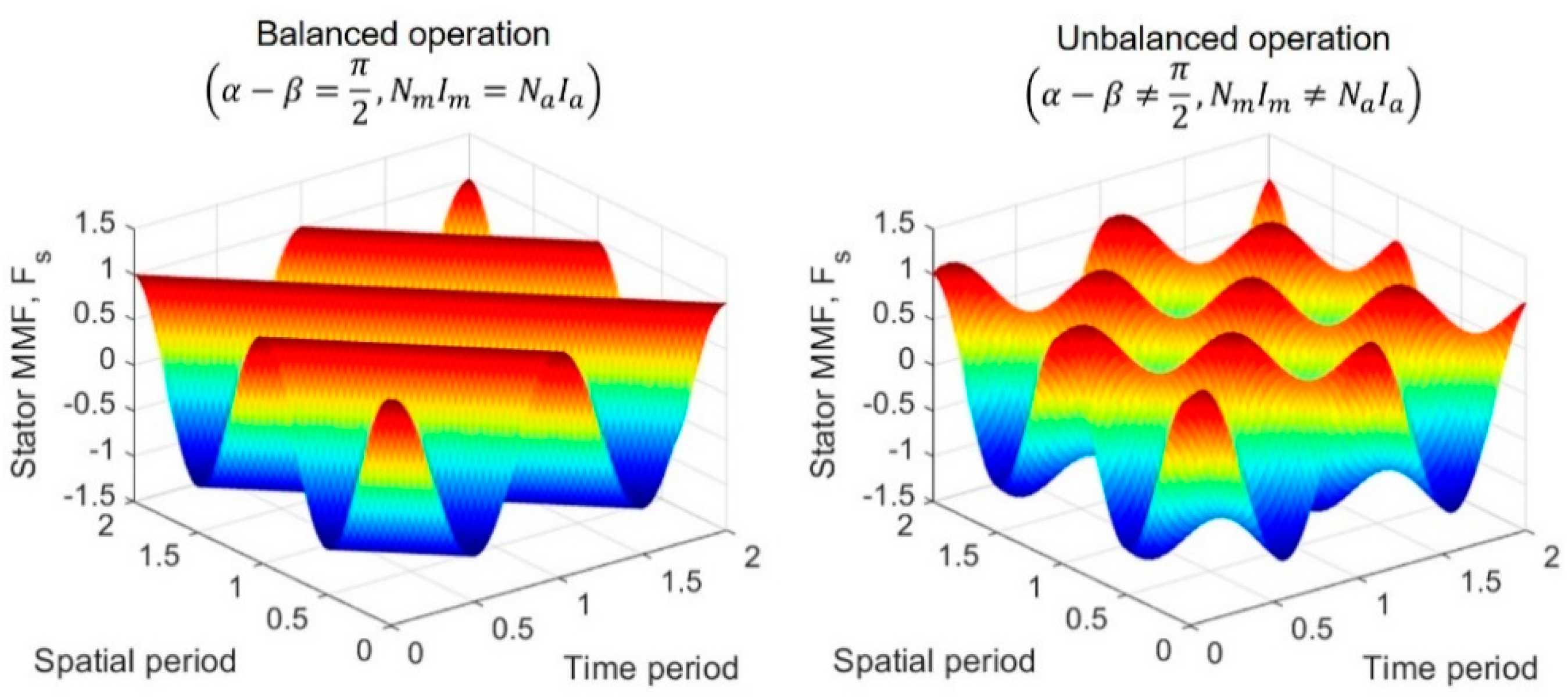
fs is the supply frequency. Spatial and temporal distribution of the stator MMF is compared between two specific load conditions, as described in
Figure 2. In balanced-load condition, the stator MMF with respect to the fundamental frequency rotates with the same magnitude at the fundamental frequency, but the fluctuation increases as the operation deviates from balanced condition.
Unlike the stator MMF, the trajectory of magnetizing MMF is rather a circular shape, referring to some researches [
3]. This is because the reaction field created by rotor MMF, thus the resultant field MMF can be simplified as the term of only forward rotating field, as written as:
Equation (4) indicates that the rotor MMF also have the term of backward RMF caused by the distribution of the stator MMF. Since the rotor MMF are created by bar currents, the effect of the unbalance condition can be characterized by analyzing the distribution of rotor bar currents using finite element analysis.
For quantitative separation of loss components using finite element analysis, stator copper loss, rotor bar loss, core-loss, and loss caused by backward RMF are calculated separately. The stator copper loss is expressed as follows using resistance calculated by reflecting the current and end winding structure of each phase.
where
T is the time period,
Rm,
Ra are the main and auxiliary winding resistance including the end-winding, and
im,
ia are the instantaneous main and auxiliary winding currents, respectively.
The rotor bar loss is the sum of the eddy current loss throughout rotor bar calculated using the calculated magnetic vector potential
Ab.
Core-loss can be estimated by the steinmetz equation and high order harmonics should be considered to reflect the distortion of magnetic field and current waveform because ignorance of harmonic components can lead to large error of the estimation [
18]. Equation (7) shows that the core-loss contains the series expression of
n times harmonics obtained by using Fourier transform of the magnetic flux density waveform in each element of stator and rotor core:
where
ch,
cc and
ce are the hysteresis, classical eddy current, excess loss coefficients, respectively. These coefficients can be obtained by curve fitting from manufacturer’s data and various frequency data are needed to calculate harmonic core-loss from exact interpolation with respect to wide frequency range. In this study, we set the constant core-loss coefficients measured at 60 Hz at all harmonic components. This is because the stator and rotor core are typically the silicon steel laminations, thus their thickness is much smaller than the skin depth at 60 Hz fundamental frequency and its space harmonic. However, an induction motor fed by a pulsewidth modulated (PWM) inverter, which have much higher fundamental frequency and carrier frequency needs variable core-loss coefficients with respect to the harmonic frequency.
The electromagnetic torque can be calculated by using the distribution of radial and tangential components
Br,
Bθ of air-gap magnetic flux density,
where
rg represents the radius of the air gap,
f is surface force density, which can be calculated by using Maxwell stress tensor method. In Equation (8), the radial component of magnetic field describes the total magnetizing MMF. In addition, the tangential component of magnetic field is discontinuous on the boundary of cores, which corresponds to the equivalent surface current on the boundary. Assuming the infinite permeability of core, and stator winding and rotor bar current as a surface current sheet, the tangential component of magnetic field can be equivalent to the distribution of stator or rotor MMF. Consequently, torque waveform follows the shape of stator MMF and the pulsating torque can be very significant under unbalanced operation.
In SPIMs, the input power is the sum of the mechanical power with respect to the positive and negative torque, stator copper loss, rotor bar loss and core-loss, as follows:
Since core-loss is not included during the simulation and obtained separately in the post-processing, the relationship between input power and output power can be written as (10). In the right hand side of Equation (10), the first term indicates the mechanical output and the last term is the loss caused by the backward RMF. Then, using known values obtained by FEM and combining (9) into (10) can represent the negative torque caused by backward magnetic field in (11).
The efficiency can be obtained by substituting (10) into (9), which is represented as
The stator winding currents, phase difference and efficiency are calculated, and the results obtained at 60% and 100% loads are compared with measured results in
Table 2.
Since the calculation at two different loads estimates the operating performance well, compared with the measured value. In
Section 3, the initial model is redesigned for the balanced-load condition at the rated load, referring to our previously published paper [
14]. The running capacitor and the number of turns in two windings are changed compared with the initial model.
3. Analysis of the Effect of Unbalanced Operation
The FE model is constructed and time-stepping fields are solved by a commercial FEM software, Ansys-Maxwell 2D-transient solver. In this paper, the simulation covers the steady-state quantities under different loads (55%, 70%, 85%, 100%, 115%, and 130% load). The varied parameters for the redesigned model is shown in
Table 3.
The calculated current and phase are illustrated in
Table 4. For the balanced-load condition, the current ratio defined in
Table 4 should be equal to the turns ratio in
Table 3. Additionally, the phase difference between main and auxiliary current should be 90 degrees, thus the redesigned model is properly redesigned for the rated load. The efficiency of the SPIM becomes maximum and decreases significantly at the lighter load.
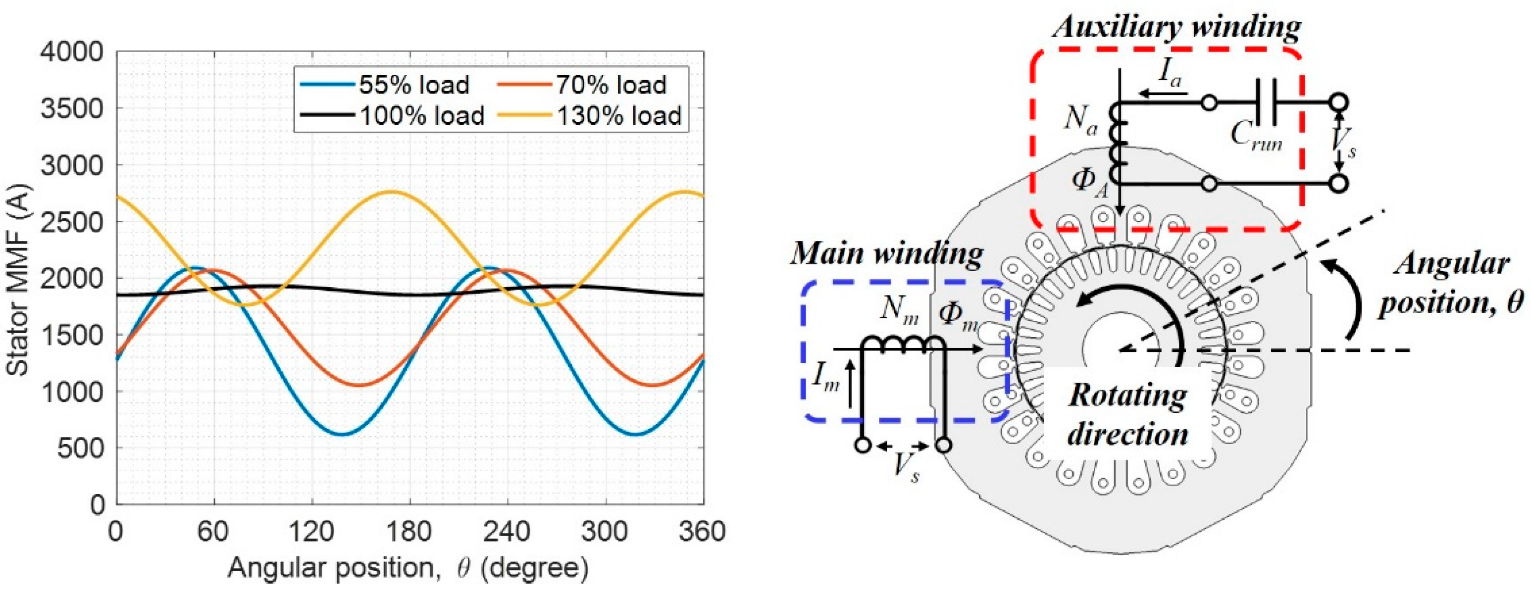
Figure 3 represents the spatial waveform of the stator MMF, which is obtained by the calculated current waveform. The magnitude and phase of the main and auxiliary winding current in
Table 4 are substituted in (3), and the fluctuation of stator MMF increases significantly as the operating load is away from the balanced-load condition. This unbalanced RMF can affect the distribution of rotor bar currents, and the consequent winding and rotor bar losses.
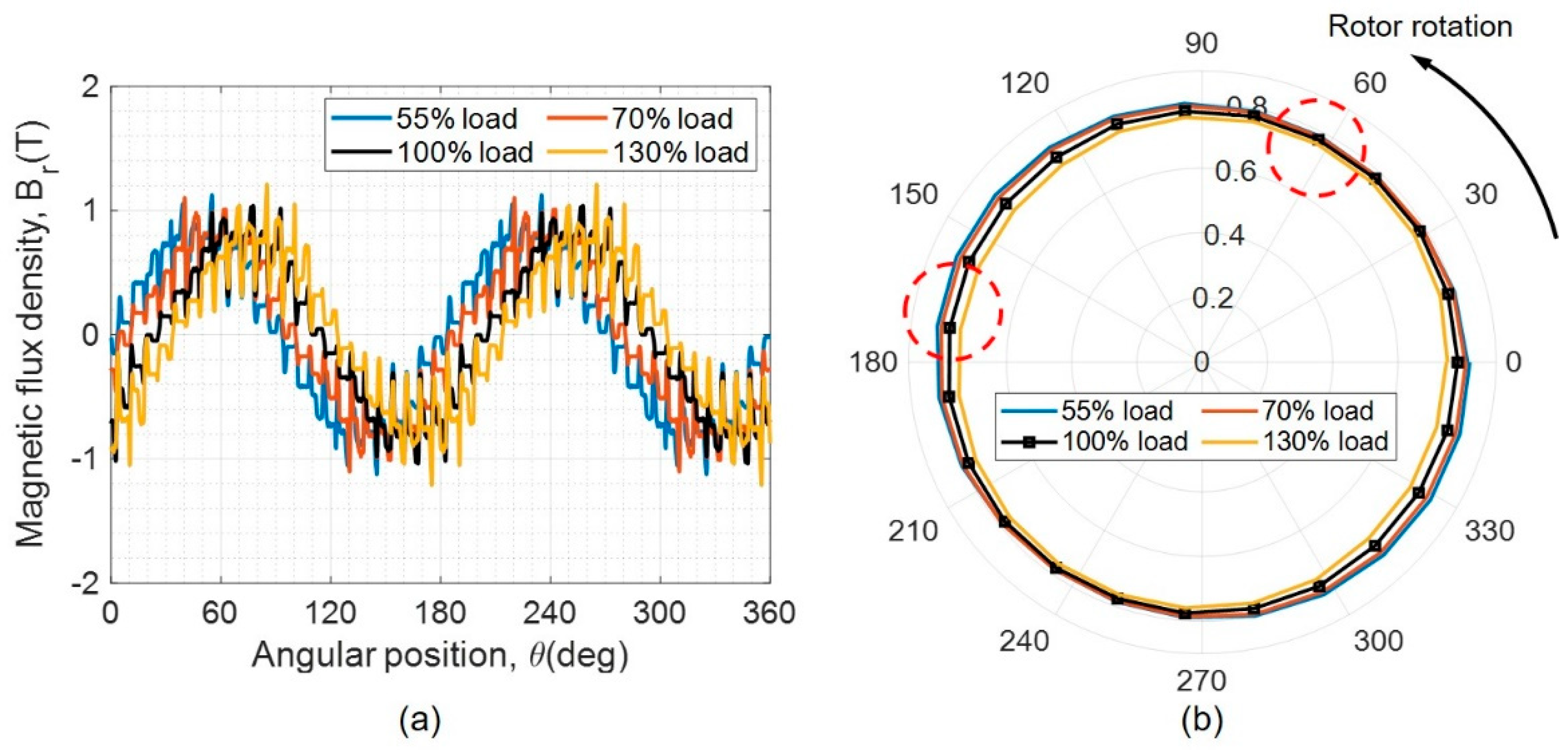
Figure 4 shows the air-gap magnetic flux density and the rotating magnetic field obtained by using 2-D fourier transform of spatial and temporal magnetic field waveform. Each value of rotating field is the peak value of the fundamental component of the magnetic flux density at each load. In
Figure 4a, the magnetic flux density is presented when the main winding current is maximum, and it can be seen that the phase of the magnetic flux density changes due to the phase difference between the main and auxiliary winding current. Referring to the dotted circle in
Figure 4, it can be seen that the rotating magnetic field is rather circular, which does not match that of the stator MMF. This is because the rotor MMF can alleviate the unbalance so that the air-gap magnetic field is not sensitive to the unbalanced condition.
As shown in
Table 5, electromagnetic losses are calculated at the different loads. The stator copper loss and rotor bar loss tend to decrease monotonically when the value of load decreases. However, the decrease rate steadily becomes small and the stator copper loss at 55% load increases despite of the lighter load. The core-loss is insignificant to the change of loads since the air gap magnetic field is rarely affected by the unbalanced condition. The contribution of negative torque is notable, but the absolute value of the change rate with respect to the different loads is not quite distinct.
The losses described in
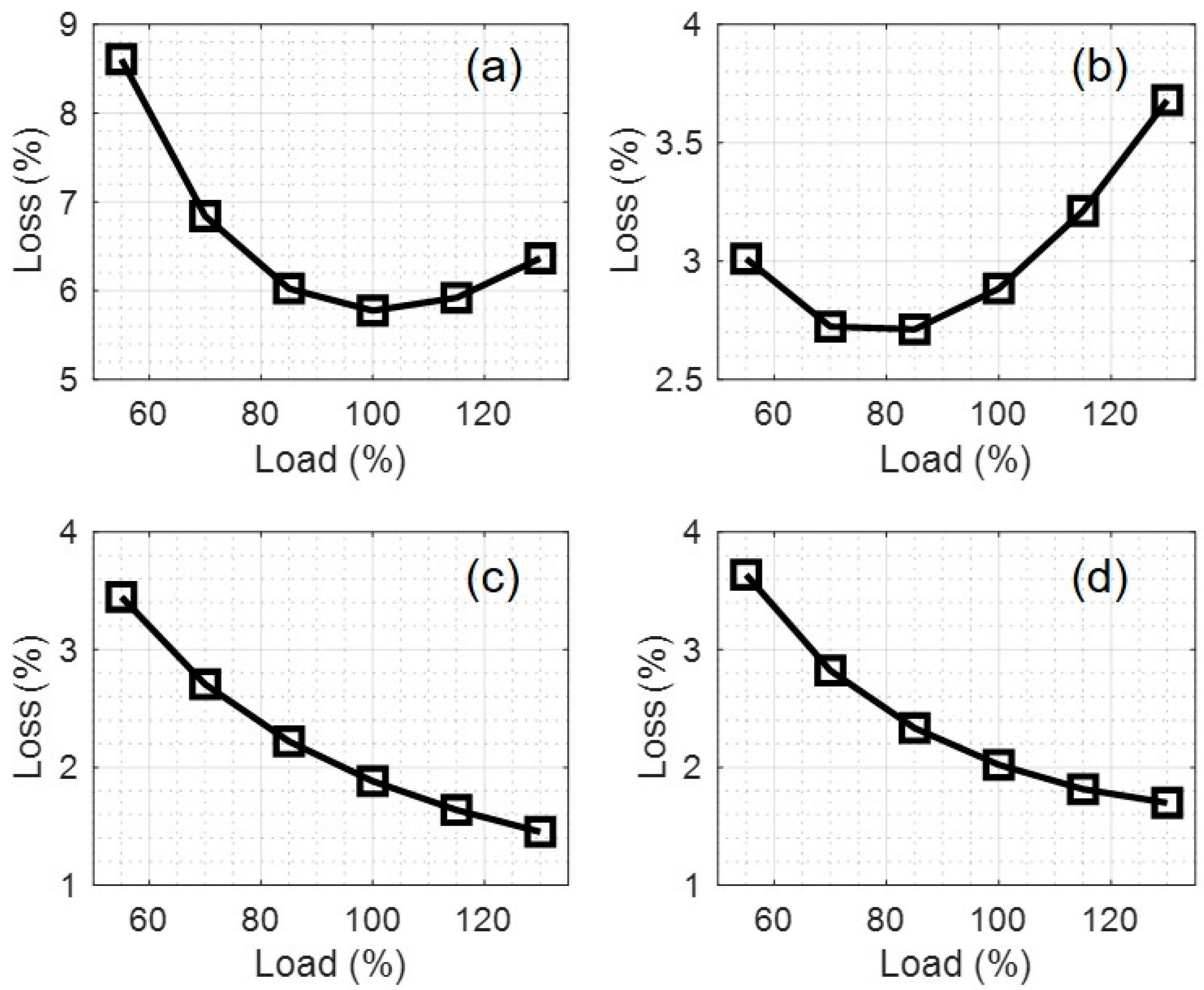
Table 5 are difficult for the fair comparison due to its different input power, so that losses are normalized by the input power at each load. As illustrated in
Figure 5, the portion of stator copper loss becomes minimum when the SPIM is running at the balanced-load condition. This is because the current is evenly distributed between the main and auxiliary winding, which is the criteria for the balanced operation of SPIMs. In general, the eddy current loss in the rotor bar increases when the heavier load is applied and the rotating speed of rotor is slower. However, the portion of rotor bar loss is almost equal or increases below balanced-load condition. The reduction of rotor bar loss can make the operating efficiency higher, which is the merit of the balanced operation. In case of the core-loss, its portion steadily decreases because the absolute value of the core-loss is not really affected by both change of loads and the unbalanced condition. The backward RMF makes the braking torque and this torque is almost constant despite of the lighter loading condition. Thus, the loss can be approximate to the constant at operating loads so that the portion of the loss increases at the lighter load.
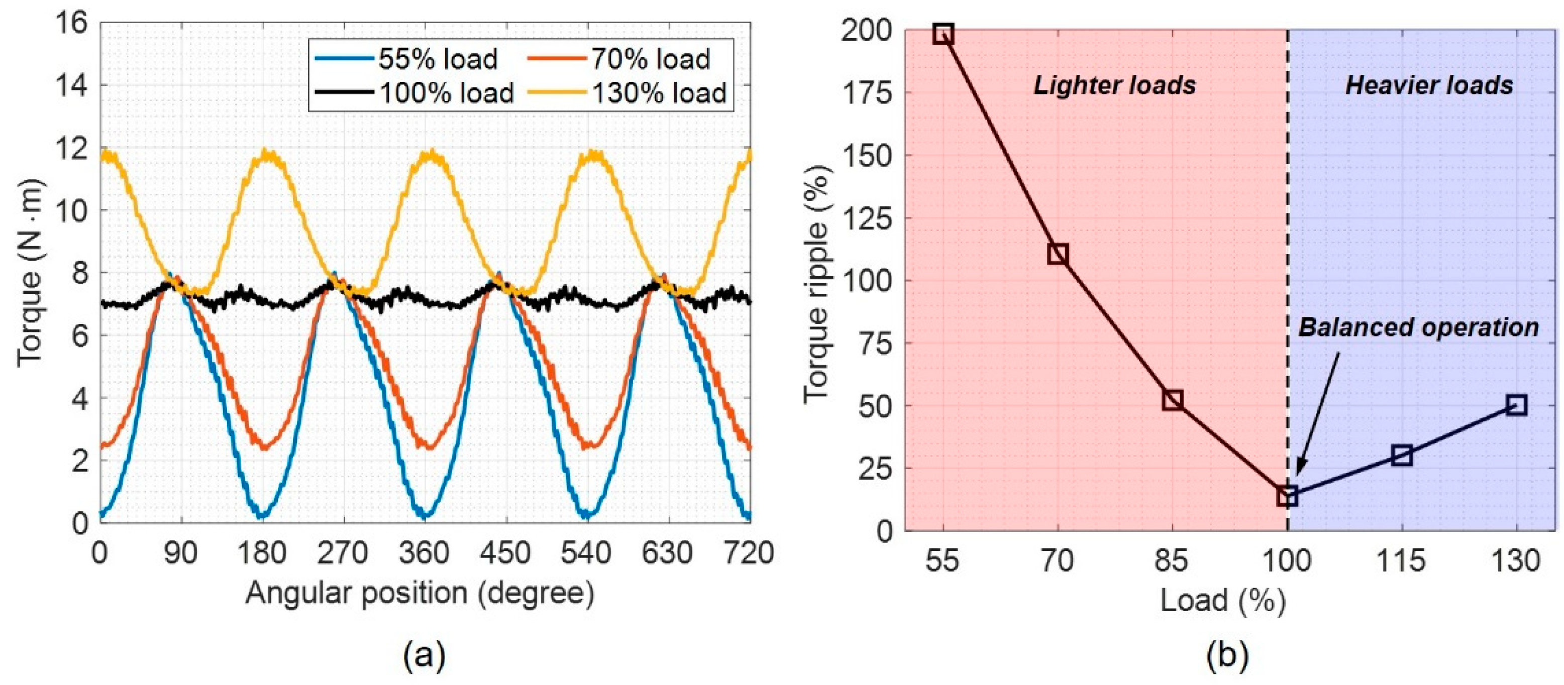
Figure 6 shows the torque waveform calculated at the different loads. As the load deviates from the balanced condition, the torque ripple largely increases. The waveform in
Figure 6 is similar to that of the stator MMF in
Figure 3. This is because the calculation of the torque contains the tangential component of magnetic field in (8), which follows the waveform of the stator MMF. Especially, the torque ripple increases more significantly at the lighter loads, which is the same trend of the efficiency variation at the lighter loads. If SPIM operates at multiple operating loads except for the balanced-load condition, optimal design focusing on the target load can deteriorate the operating performance at other operating points, especially at the lighter load. Therefore, the selection of the proper load is required for the application using multiple operating loads, and this will be discussed in
Section 4.
4. Discussion
The result indicates how the unbalanced operation affects the electromagnetic quantities such as the air-gap magnetic field, the subsequent losses, torque. The loss caused by the backward RMF occupies a large portion of total losses, but the absolute value is not sensitive to the change of loads. The torque ripple dramatically increases under unbalanced operation. The air-gap magnetic field is rather circular, but the stator and rotor MMF can be still distorted because of uneven distribution of currents. The Lorentz force on stator windings and rotor bars can be applied and the distribution of force will follow the distribution of each current. Since the force is proportional to the current flowing into the rotor bar, the uneven distribution of current can lead to magnify the force on the rotor bar. The locally concentrated force will make the vibration and acoustic issue. Thus, the design of SPIMs can face the bottleneck unless the SPIM is primarily designed to run at the balanced-load condition and the further research dealing with the electromagnetic force and its structural effects is necessary. In
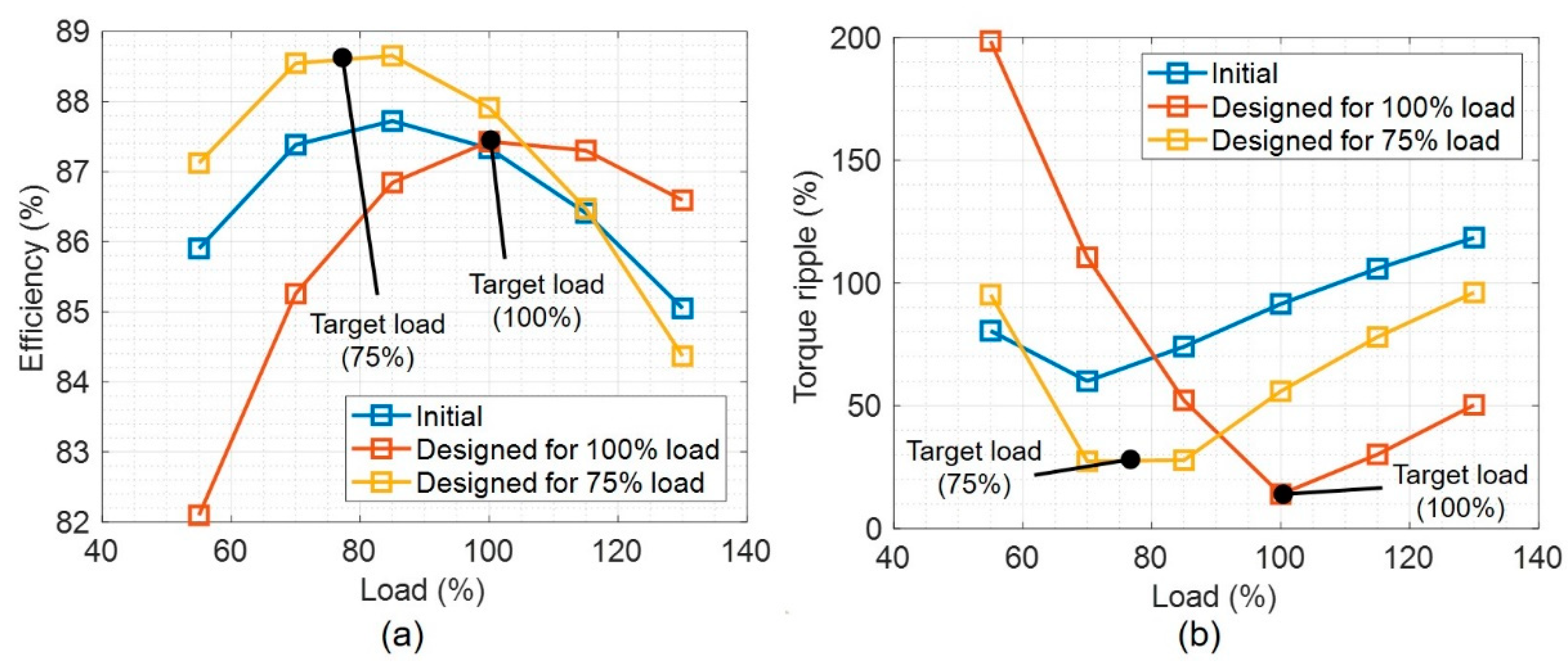
Section 3, we developed the redesigned model and the model shows the improvement of the performance. However, the disadvantages of making balanced-load condition at the rated load is that the operating characteristics drastically deteriorate compared with the balanced operation. Therefore, it is necessary to find a suitable design target point when SPIM is not used at the fixed operating point. Additionally, redesigned model is dealt to compare with the models designed for the different loads. In the same method, the capacitor and the number of turns in windings are changed and their values are shown in
Table 6.
Figure 7 illustrates the efficiency and torque ripple of each model at different load. Compared to the model designed for 100% load, the model designed for 75% load shows wider operating efficiency characteristics for both the rated and lighter loads. In particular, the model designed for the 100% load shows the lower efficiency than that of the original model at the lighter load. On the other hand, the model designed for 75% load not only exhibits high overall characteristics compared to the initial model, but also shows higher efficiency characteristics than the designed model for the 100% load. Torque ripple has the similar tendency to the efficiency. However, the torque ripple is minimum at the balanced condition and increases rapidly as it is away from the balance, thus the efficiency and torque characteristics must be considered mutually.
Further, typical SPIMs run with a capacitor to generate the rotating magnetic field, and the frequency response of SPIM has a unique operating point for the magnetically balanced condition. The idea is to adjust the frequency response of SPIM to the desired loading condition, or increase the order of the frequency response to make multiple balanced conditions. The former usually can be solved by utilizing the various frequency inverter to adjust the supply frequency [
9,
10,
11]. The latter can be achieved by the pole changing method or adding multiple capacitor with poly-phase windings [
5,
6,
7,
8,
12].

