1. Introduction
The U.S. Army’s modernization challenges include reducing the logistic burden of storing, transporting, distributing and recycling essential materials. In addition, there is a great need for reducing the lifecycle cost of the U.S. Army’s future advanced capabilities. With newer materials such as ceramic matrix composites (CMCs) introduced into future U.S. Army rotorcraft gas turbine engine designs, there is a pressing need to monitor the health conditions of these materials in engine operations, since we lack field usage knowledge of these material components in the U.S. Army’s mission flights. Currently, there is no reliable direct or in situ technique for measuring high temperature or strain in the hot sections of turbine engines [
1]. Advanced sensors have been developed over time, but none is capable of meeting the requirements for monitoring engine hot sections [
1,
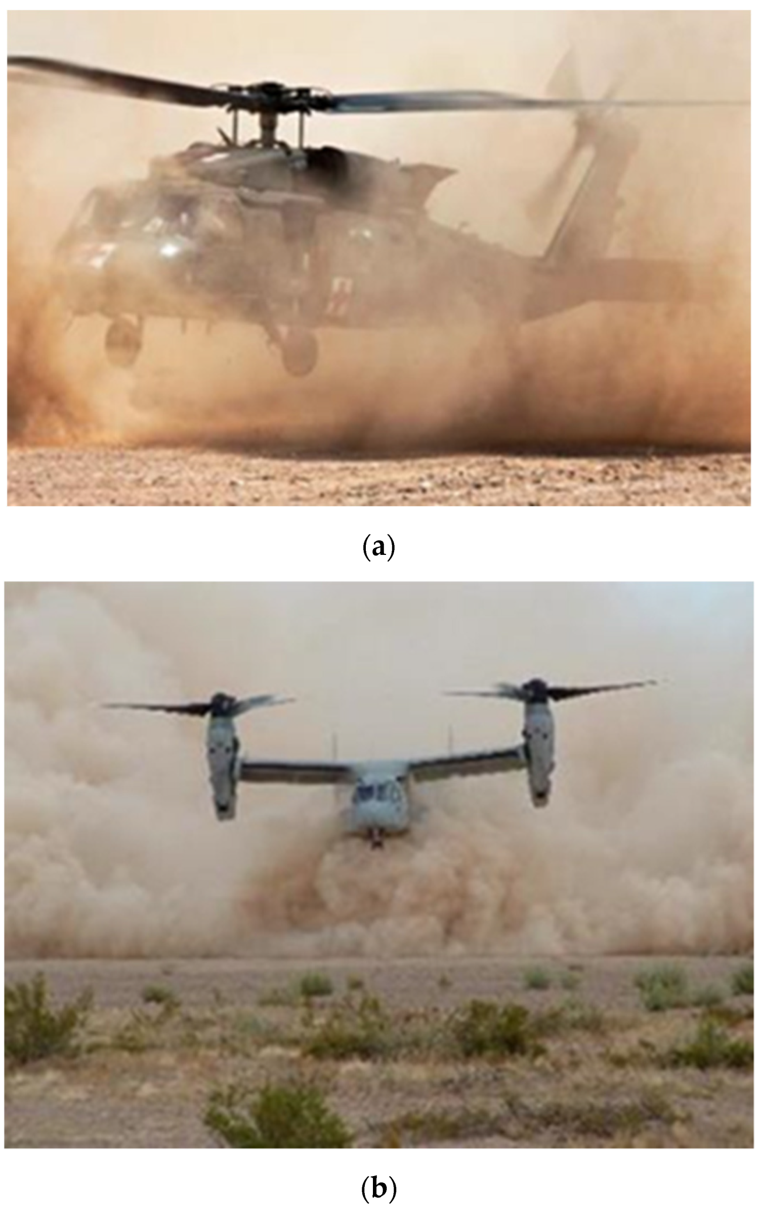
2]. Knowledge gathered from embedded sensor technologies will pave the way to reduce lifecycle costs of future gas turbine engines for U.S. Army helicopters. Efficient health monitoring with advanced sensing systems will provide highly reliable gas turbine engines for mission availability and enhance soldier safety at all times. Health monitoring of critical engine components becomes absolutely necessary when military helicopters operate under harsh conditions, such as severe sand storms or brown-out conditions during take-off or landing operations in desert regions (
Figure 1) [
3,
4]. NASA has previously demonstrated a high temperature strain gage based on palladium chromium (PdCr) thin films capable of operation up to 1100 °C [
5]. Reference [
6] gives details of ceramic thin film thermocouples developed for SiC-based ceramic matrix composite (CMC) substrates. Willsch et al. [
7] reported a novel approach for the design of fiber-optic-based high-temperature sensors for gas turbine monitoring. Riza and Sheikh [
8] gave details on the development of silicon carbide-based extreme environment temperature sensor using wavelength-tuned signal processing. Wong et al. [
9] have reported development of RTD (resistance temperature detector)-based high-temperature embedded sensors by exploiting the predictable and reproducible change in the resistance of a material with changes in temperature. In spite of all the past development work, insertion of reliable in situ or embedded sensor technologies into turbine engine hot-section components is still a significant technical challenge.
The development of fiber-optic sensors has advanced over the past many years. In the early 1980s, there was a prediction that fiber-optic sensors would compete eventually with other solid-state sensor technologies in gaining wide use by the industry [
10]. Fiber-optic sensors are promising for sensing applications because of their advantages in terms of small size, light weight, immunity to EM interference, resistance to chemical attacks and multiplexing capability. Therefore, there have been continuous research and development efforts on fiber-optic sensors for various niche applications in vehicle component health monitoring. These include pressure, strain, flow measurement, temperature measurement, etc. There have been several reported successes using fiber-optic sensing technologies for strain monitoring [
11], temperature sensing [
12], and other sensing applications as discussed in the references [
13,
14]. The effect of temperature on the response on fiber Bragg gratings has been discussed together with appropriate fabrication methods in [
15]. For embedded sensing, substrate application techniques including surface bonding and proper methods of embedding are discussed in references [
16,
17,
18]. For any sensor, besides sensitivity, durability plays a key role in long-term health monitoring applications. Typically, fiber Bragg gratings (FBGs) show a decay in reflectivity under elevated temperatures. This decay decreases with time and settles to a quasi-stable value over long time use. Hence, to obtain stable FBG sensors, thermal annealing is usually performed prior to embedding on a component [
19]. For high temperature applications exceeding 500 °C, the normal type FBGs with a polymer based coating cannot be used due to the strong decay in reflectivity. However, for temperatures up to the 700–800 °C range, special types of FBGs have been fabricated. These FBGs together with high temperature coatings make them suitable for long term embedded monitoring of components that perform continuously under high temperature conditions [
20]. Additionally, the optical fiber distributed temperature sensors provide the unique capability of monitoring the temperature profile of a component along the length of the fiber embedded onto the surface of a component [
21].
As per the Brayton thermodynamic cycle [
22], increasing the turbine inlet temperature enhances the overall gas turbine engine efficiency and the power density. The development of uncooled turbine blades and other hot-section components will be enabled in gas turbines in future with the advent of new higher temperature capable engine materials, e.g., CMCs and novel coating materials such as sand-phobic thermal/environmental barrier coatings (T/EBCs) [
3,
4]. Due to high temperature environments and rotating small blade passages with inaccessible zones for sensor placement, the blade surface temperature is often predicted from engine gas dynamic path analysis. Currently, there does not exist any viable method to enable a non-intrusive sensing system that is capable of monitoring the physical properties of the hot-section gas turbine blades and the integrity of blade thermal barrier/erosion resistant coatings. Therefore, under this FTAS funded research effort, U.S. Army Combat Capabilities Development Command (CCDC) Army Research Laboratory (ARL) has evaluated the usage of a minimally intrusive measurement technique using embedded FBG sensors to monitor the temperature of turbine blade substrate and/or coating material surfaces to enable health monitoring of critical components in future gas turbine engines. The intended outcome of this effort is an evaluation of embedded sensing methods for in situ, non-intrusive or minimally intrusive health monitoring of engine components that can support U.S. Army vehicle sustainment efficiently with well-informed usage-based maintenance actions for gas turbine engine components operating in harsh engine environment. This paper presents the embedded FBG sensor placement techniques on typical turbomachinery material specimens, made of Ti-6Al-4V and IN718 alloys, temperature measurements and sensor sensitivity responses with thermal cyclic conditions. The sensor responses are compared with a thermocouple, which is also embedded at the same location in proximity to the FBG sensor provided by Epsilon Optics Ltd., Fordingbridge, UK.
2. Sensor Technology
Unlike other strain measurements, fiber Bragg grating sensors (FBGs) offer a wide measurement range and excellent linearity and repeatability over many millions of load cycles. Since the interference pattern is permanently written into the glass, the FBG sensor can provide an absolute reference for strain measurements over the entire operating lifetime of a structure without the need for recalibration. Other benefits include immunity from EMI (electro-magnetic interference) and the capability of multiplexing up to 100 sensors on a single optical fiber, thus minimizing cabling and installation costs and improving overall reliability. In addition to being sensitive to strain, FBGs are also sensitive to temperature. For many strain-sensing applications on engine structures under both thermal and mechanical loads, it is necessary to compensate for temperature effects. There are a number of ways of doing this effectively, the simplest of which is to install a second FBG that is isolated from the strain in the structure but subjected to the same temperature as the strain sensing FBG. Additionally, the temperature response of the FBG can also be used as the basis of a temperature sensor either by using an unstrained FBG or by bonding it to a carrier with a high coefficient of thermal expansion in order to provide enhanced response. The fiber-optic sensing system includes a suitable opto-electronic unit to interrogate the FBGs. The interrogation unit sends broadband light down the optical fiber and accurately measures the wavelengths of the light reflected back from the FBGs. Since there are many FBGs written into a single optical fiber, the interrogation unit must be able to determine which reflection came from which FBG. There are mainly two ways in which this can be done: (i) wavelength division multiplexing (WDM), and (ii) time division multiplexing (TDM).
The temperature response of an FBG is primarily due to the change in refractive index with temperature, but is also as a result of thermal expansion of the glass. As the temperature increases the fiber expands and the wavelength of the pulses of light that the FBG reflects increases and vice versa. Therefore, for accurate measurement it is essential to isolate the FBG from any strain due to mechanical loads in the component to which it is attached. High temperatures cause the glass to anneal and the FBG to fade until it no longer reflects light with sufficient intensity for the wavelength to be measured. This effect can be delayed by writing a very strong FBG with a high level of reflectivity.
Epsilon Optics Ltd.’s sensor patches make use of fiber Bragg gratings (FBGs) for measuring strain and/or temperature. Epsilon Optics has developed a number of methods for encapsulating the FBG and fixing it to the structure so that it is isolated from mechanical strain and thus measures only the effect of temperature.
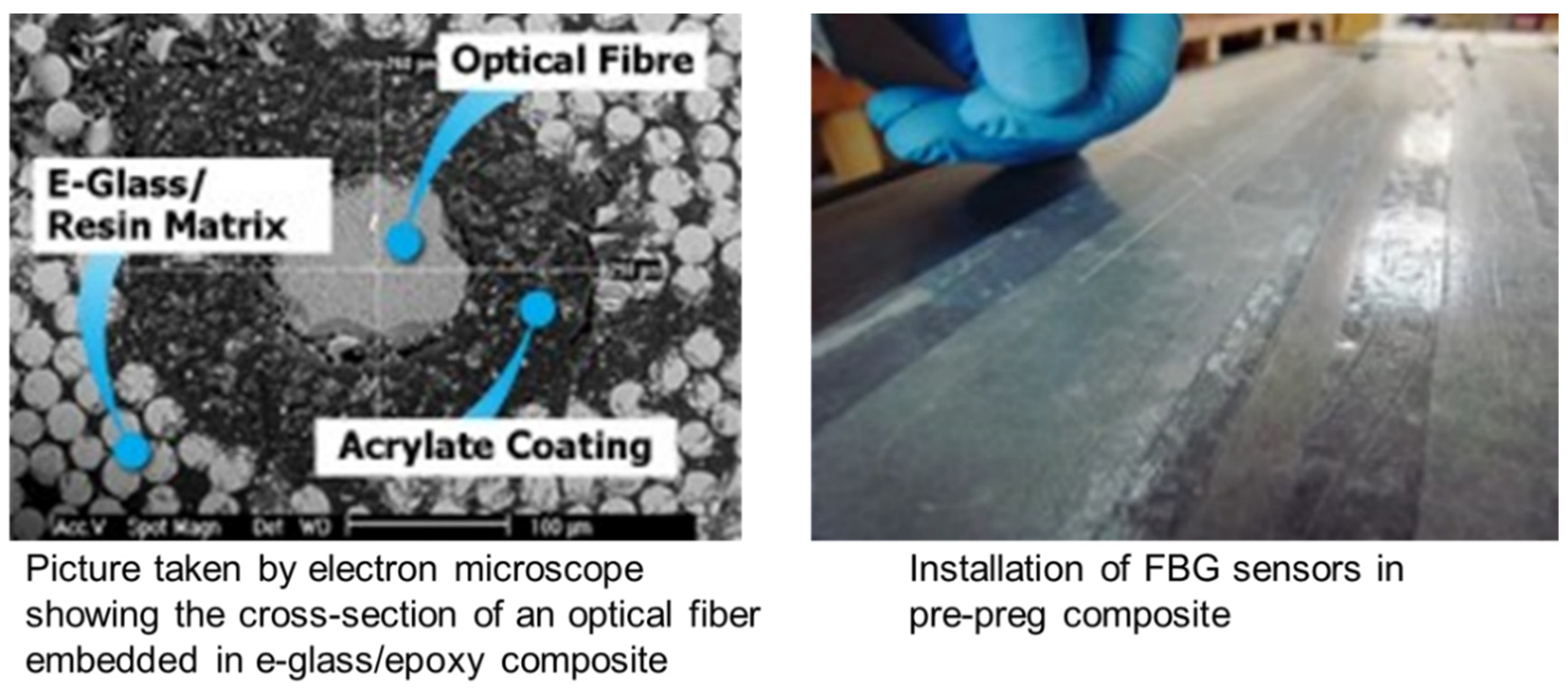
Figure 2 and
Figure 3 show surface bonded and embedded sensor examples from Epsilon Optics Ltd.
Figure 2 shows a flexible strain sensor patch, custom strain sensor patch and temperature sensor patch used in typical structural health monitoring applications.
Figure 3 shows an embedded sensor patch used in composite structure health monitoring applications. Epsilon’s sensor development is such that the high temperature effect on FBG’s degradation can be delayed by using a femtosecond laser to produce the FBG. FBGs written with this technique have achieved around 700 °C. There are potential advancements in this area that need to be investigated to make available FBGs that can achieve a ~1000 °C capability.
Historically, FBGs have been inscribed within optical fibers using ultra violet (UV) light to create various photo-chemical effects within the core of an optical fiber. These effects create the required variation along the length of the fiber, otherwise known as fringes, which allow the FBG to act as a wavelength-selective reflective mirror. This process has worked extremely well for decades of use within telecommunications, lasers and benign environmental sensing applications. However, it has long been understood that such FBGs have limited use in harsh environments due to the photo-chemical processes being reversible once high temperatures are reached. UV-inscribed FBGs continuously erase over time, with the erasure process dramatically accelerated with temperature. The typical approach to handling this issue is to pre-anneal the FBG such that the FBG is effectively aged before it reaches the end user. Pre-annealing requires the fiber to be exposed to substantially higher temperatures than the final operating temperature. This works well up to 300 °C, however above this temperature range, the thermal annealing process elevates the FBG to such a high temperature that it almost completely erases before it reaches stability. This limitation drove the development of a fundamentally different inscription method, using femtosecond infrared lasers rather than UV lasers. Femtosecond lasers deliver a substantially higher energy level into the core of the fiber than a UV laser, creating large energetic changes in the atomic matrix. Subsequently, these effects are substantially more challenging to erase from the optical fiber and requires the glass of the optical fiber to be brought close to the point where the glass is starting to melt or flow. According to Dr. Andy Gillooly of Fibercore, U.K, who performed the sensor fabrication for this effort, these FBGs are femtosecond written but are not inscribed with a point-to-point method, rather they have been inscribed with a phase mask technique, much like the standard UV laser approach. Femtosecond FBGs have a greater tendency to incur higher birefringence than a UV-inscribed FBG, as the FBG can extend into the cladding and utilizes a very small focal area. Therefore localized refractive index asymmetry within the core is possible. UV-inscribed FBGs are less prone to this, as the refractive index variation is kept within the geometry of the core and thus is bounded by a circular cross-section, subsequently removing any shape birefringent effects. Point-to-point femtosecond FBGs can result in higher birefringence than phase mask based femtosecond FBGs as the method of focusing and inscribing is less refined, ultimately resulting in the fiber’s glass material being more aggressively modified locally [
23,
24]. Academically, reports have been made of femtosecond FBGs showing stability at 1000 °C, whilst most commercial offerings state more modest limits of around 750 °C before the FBG starts to erase [
23,
24]. Irrespective of test methodology and nuances associated with different methods of inscribing femtosecond FBGs, in a side-by-side comparison, UV-inscribed FBGs always erase far in advance of femtosecond inscribed FBGs. For high-temperature, harsh environment FBG sensing applications, femtosecond FBGs are the primary choice for repeatable, long term performance. While standard FBG sensor patches have been evaluated and verified in various structural health monitoring applications including aerospace fuselage and landing gear, additional research and development is needed to validate femtosecond FBGs for the health monitoring of high-temperature engine components.
3. Experimental Set-Up
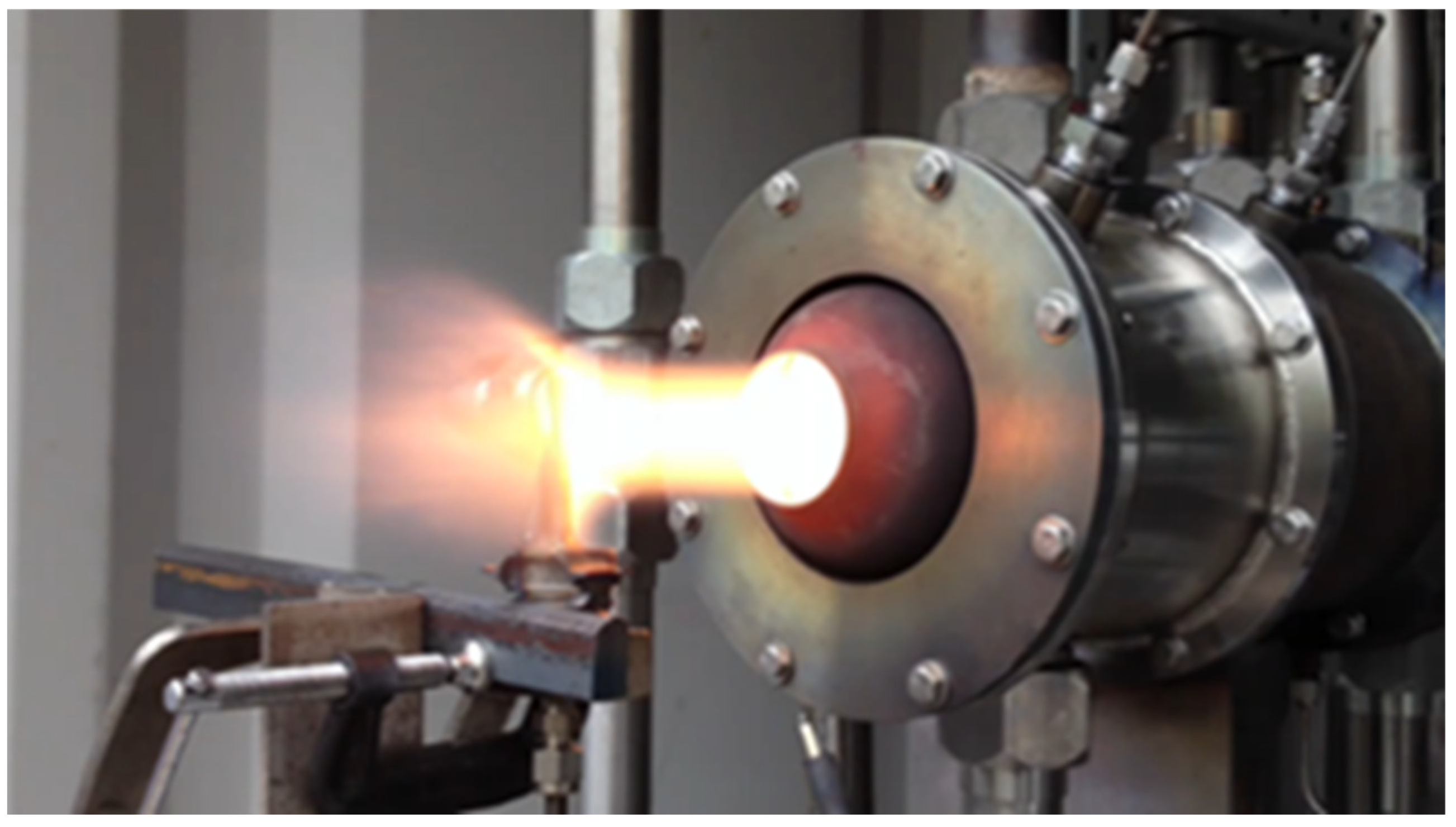
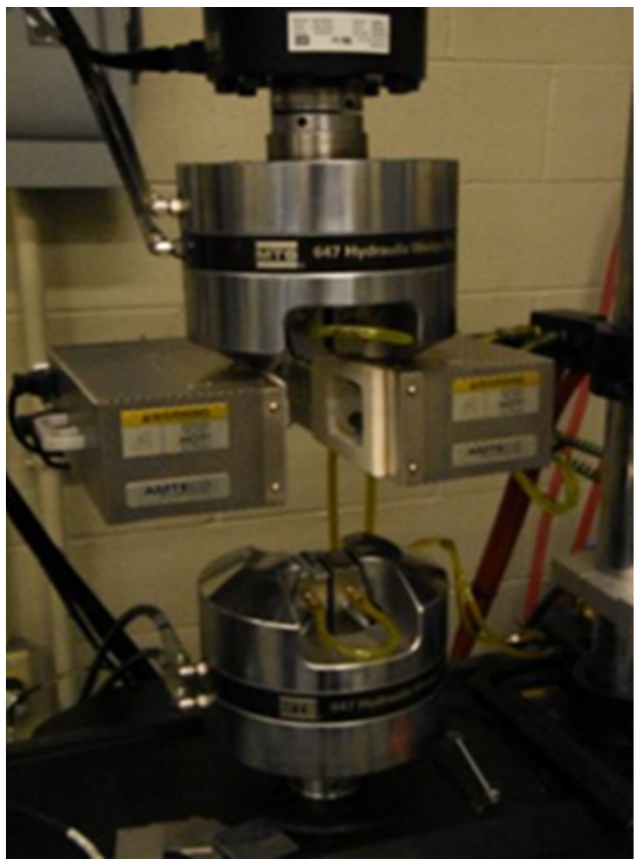
CCDC-ARL is equipped with a high-temperature jet burner rig (
Figure 4), and Measure Test Simulate (MTS) thermomechanical test rig (
Figure 5) to conduct high-temperature thermal cycling and thermomechanical fatigue tests. Sand/salt ingestion tests can also be conducted to evaluate the durability of embedded sensors on engine component material specimens under harsh dusty or corrosive environments relevant to military operations. The jet burner rig shown in
Figure 4 is capable of reaching temperatures of up to 1982 °C (3600 °F) gas temperature to be able to test emerging high temperature CMC material specimens. The MTS thermomechanical fatigue (TMF) rig shown in
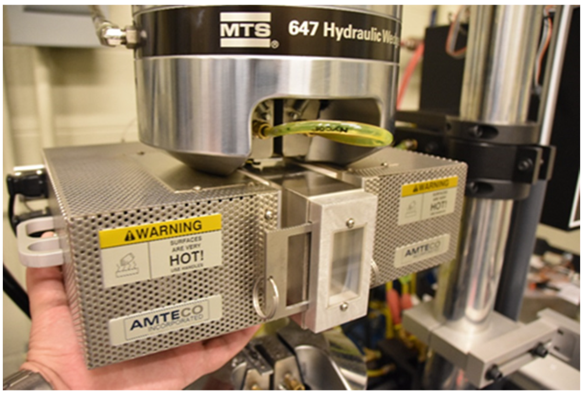
Figure 5 is equipped with a box furnace that can reach up to 1500 °C. It is electronically controlled and integrated into the TMF rig for conducting thermal cycling together with in-phase or out-of-phase mechanical cycling loading capability. The high-temperature furnace is also equipped with a Sapphire window port (as shown in
Figure 6) that can be used for DIC (digital image correlation) strain measurements on specimens.
For this research, the TMF rig was used to test embedded sensors on material specimens under varying thermal conditions using the close-loop controlled box furnace. Material specimens were specially designed, and embedded with FBG sensors that could fit in the box furnace. The specimen embedded with the sensor was attached to the TMF rig’s grips. One of the material specimens, Ti-6Al-4V with embedded FBG sensor from Epsilon Optics, is shown in
Figure 7. The test specimens were tested under varying temperature conditions for long durations of up to 60+ h and also underwent long-duration repeated test runs.
Thermal cycling durability tests were conducted using the TMF test rig with embedded FBG sensors placed on four Ti-6Al-4V (Ti6Al4V) material specimens and four Inconel 718 (INC 718) specimens. In all the specimens, thermocouples were attached side by side with FBG sensors to help correlate the sensor sensitivity response and accuracy. The temperature sensing responsiveness and thermal cycling durability tests were conducted for long durations of up to ~62 h continuously by ramping up the temperature steadily and holding the furnace temperature setting at different levels for prescribed time durations. Repeated long-duration thermal cycling tests were also conducted. The acquired temperature data from the FBG sensors and the thermocouple measurements are compared and presented in the “Results and Discussion section”. Some of the sensors were tested under cycling temperature conditions beyond the temperature limit of the sensor to examine the failure trends. Lessons learned from this research can enable innovation of a novel in situ sensing technique to monitor the health state of turbomachinery blade substrate and/or coating materials for future gas turbine components operating under austere environmental conditions.
4. Results and Discussion
During the beginning of the experimental evaluations, the embedded FBG sensor’s response in characteristic wavelength measurements from the interrogator were correlated to temperature readings from the thermocouple that was placed adjacent to the embedded FBG sensor.
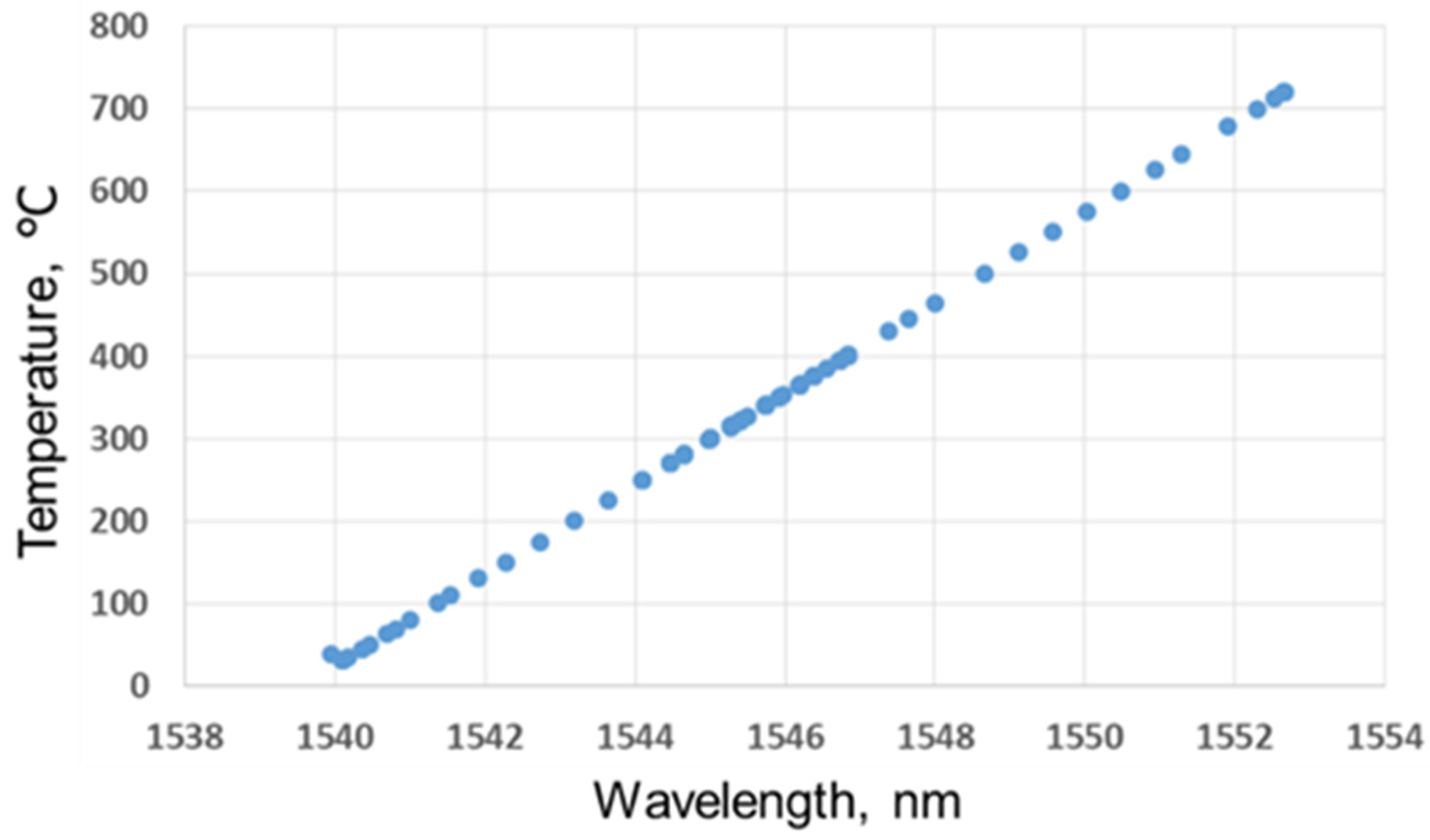
Figure 8 shows the correlation between the measured characteristic wavelength change and the measured temperature from the thermocouple placed in close proximity to the FBG sensor. This is typically a linear relation within the temperature limits for a given type of FBG sensor. For the sensor used, the limit temperature was found to be around ~720 °C, after which the signal strength fell much below the threshold and failed. The sensor calibration curve shown in
Figure 8 was used to convert the characteristic wavelength recordings from the FBG sensor into calibrated temperature data.
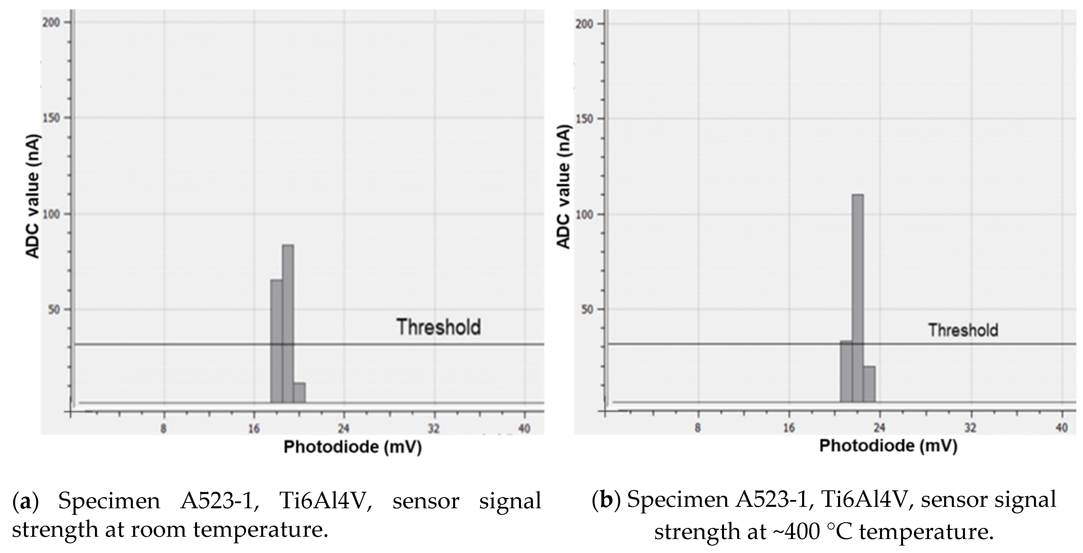
The signal strength for each FBG sensor was also monitored during the thermal cycling experiments. The sensor signal strengths are shown for the FBG sensor embedded onto the Ti6Al4V specimen (numbered as A523-1) at room temperature (
Figure 9a) and at an elevated temperature of ~400 °C (
Figure 9b). As seen from
Figure 9a,b, the signal strength was strong in this temperature range, much above the threshold setting enabling reliable measurements at this range of temperature conditions.
Figure 9b shows that the sensor signal strength for the same Ti6Al4V specimen (A523-1) at 400 °C is clearly strong and still good above the threshold at this higher temperature, ensuring reliable measurements.
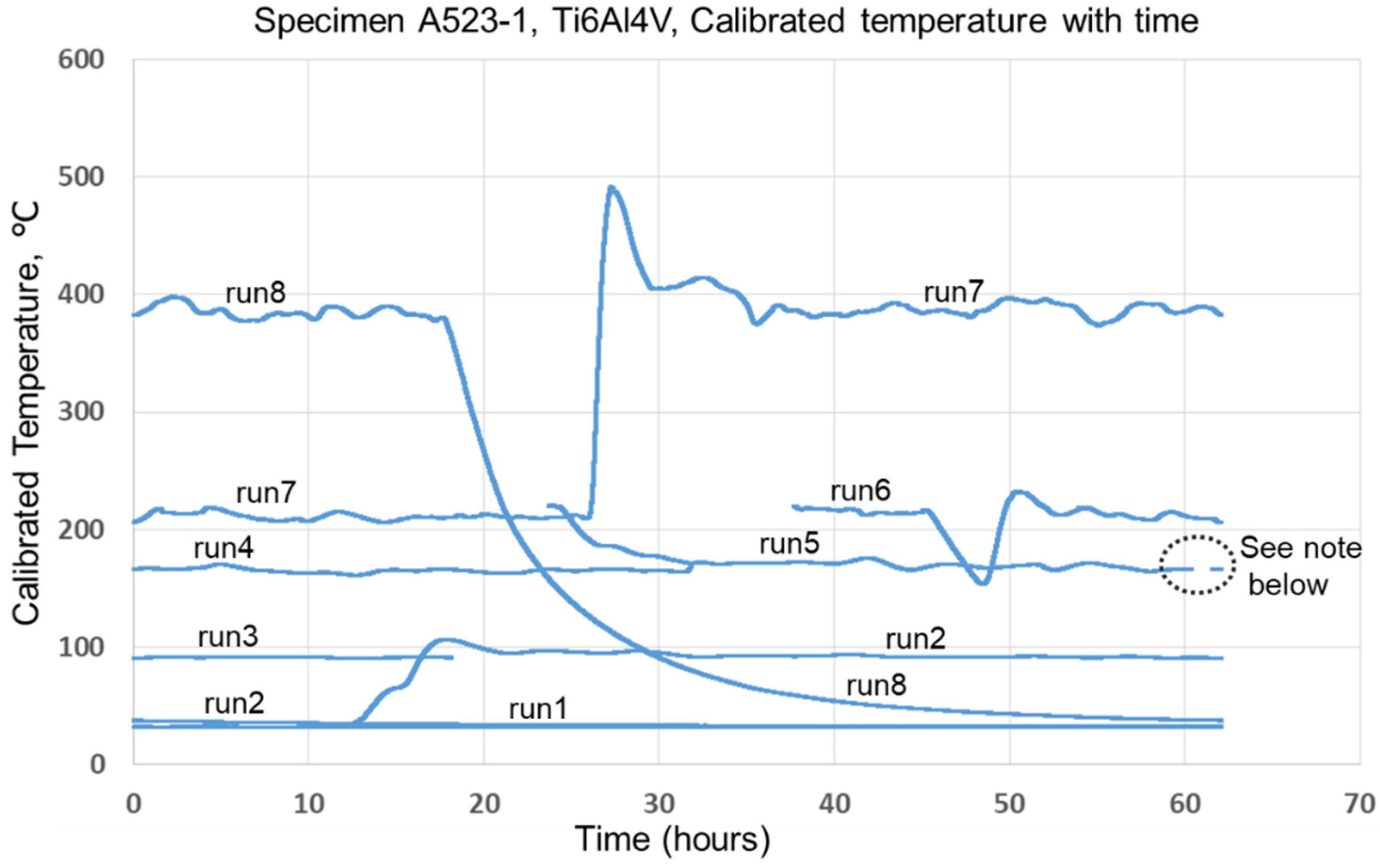
Figure 10 shows the calibrated temperature data during thermal cycling experiments on the Ti6Al4V specimen (numbered as A523-1) with the embedded FBG sensor over several runs. The thermal cycling test runs were performed over a period of 2+ days (~62 h) continuously and the measurements were recorded. A built-in time stamp counter in the interrogator was used to plot the characteristic wavelength recordings. These were converted to calibrated temperature data as shown in
Figure 10 along with elapsed physical time.
As observed from
Figure 10, the temperature data during some of the high temperature runs, especially run 7 and run 8, appear to be wavy which could be due to the effect of the furnace controller constantly adjusting to keep up with the set temperature level. The furnace could not be perfectly sealed, resulting in some heat loss from the furnace caused by radiation and also from the water cooled specimen grip. At 4% vanadium, the Ti6Al alloy is in the alpha + beta phase field. As the temperature rises above 400 °C, the alpha content demonstratively reduces and continuously transforms to the beta phase. The base material phase change will thus affect the embedded FBG sensor reading. Hence, the user should be mindful of these uncertainties while using such embedded sensing methods. However, in general, gas turbine engine components consistently monitored using embedded sensing can be beneficial in detecting anomalies during mission flights (especially during extreme maneuvers) and provides the ability to locate and correct problems before any catastrophic failure occurs.
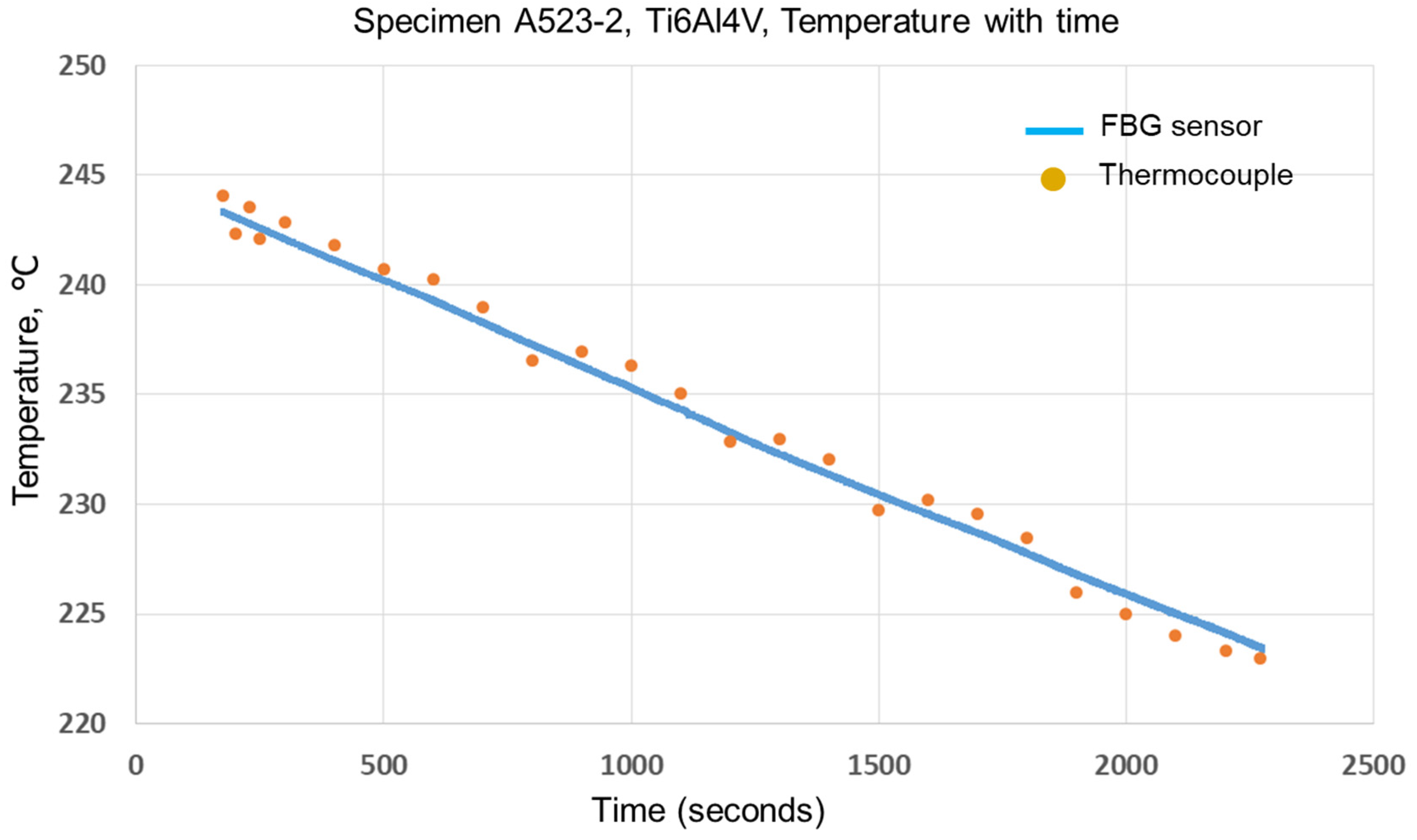
Figure 11 shows the temperature history plot for the Ti6Al4V specimen A523-2, which was tested under ramp-down temperature conditions controlled by the AMTECO furnace fitted to the test rig. During this test, the ramp down started from a temperature of ~244 °C and went down to a temperature of ~224 °C, showing the FBG sensor performed well in this small range (
Figure 11). The temperature readings from the thermocouple placed in proximity to the FBG sensor are also plotted in
Figure 11. The thermocouple measurements were acquired at 0.2 Hz, and so they are shown at discrete time steps to show the comparison. In general, both data agreed well within a ±1% error.
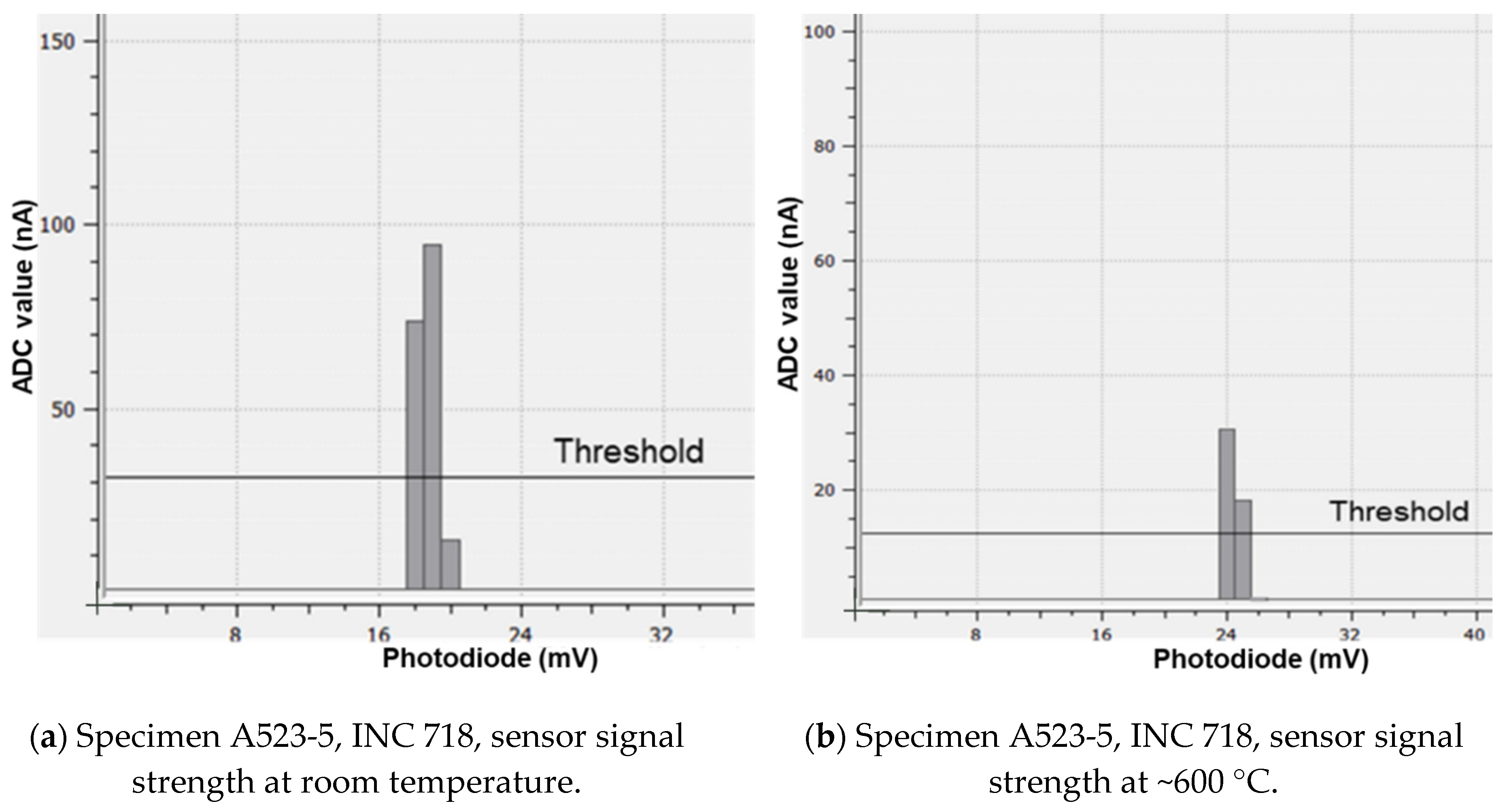
In order to test the sensor’s decay of signal strength at higher temperatures, the experiments were conducted at increased temperatures in steps, and the signal strength response at different temperatures were captured. The
Figure 12a–d show the sensor’s recorded signal strength for the INC 718 specimen (numbered as A523-5) at room temperature, 600 °C, 700 °C, and slightly greater than 720 °C, respectively. There was complete loss of signal at slightly greater than 720 °C, which suggested that the maximum limit operating temperature for this embedded FBG sensor is 720 °C.
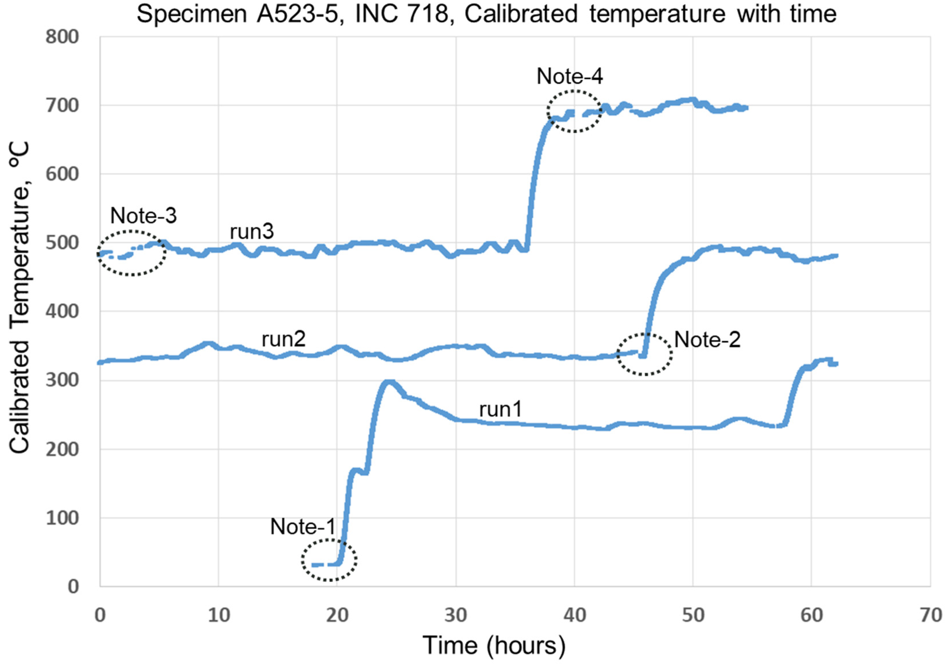
Figure 13 shows the calibrated temperature data with time for the sensor embedded onto the INC 718 specimen (numbered as A523-5). As observed from
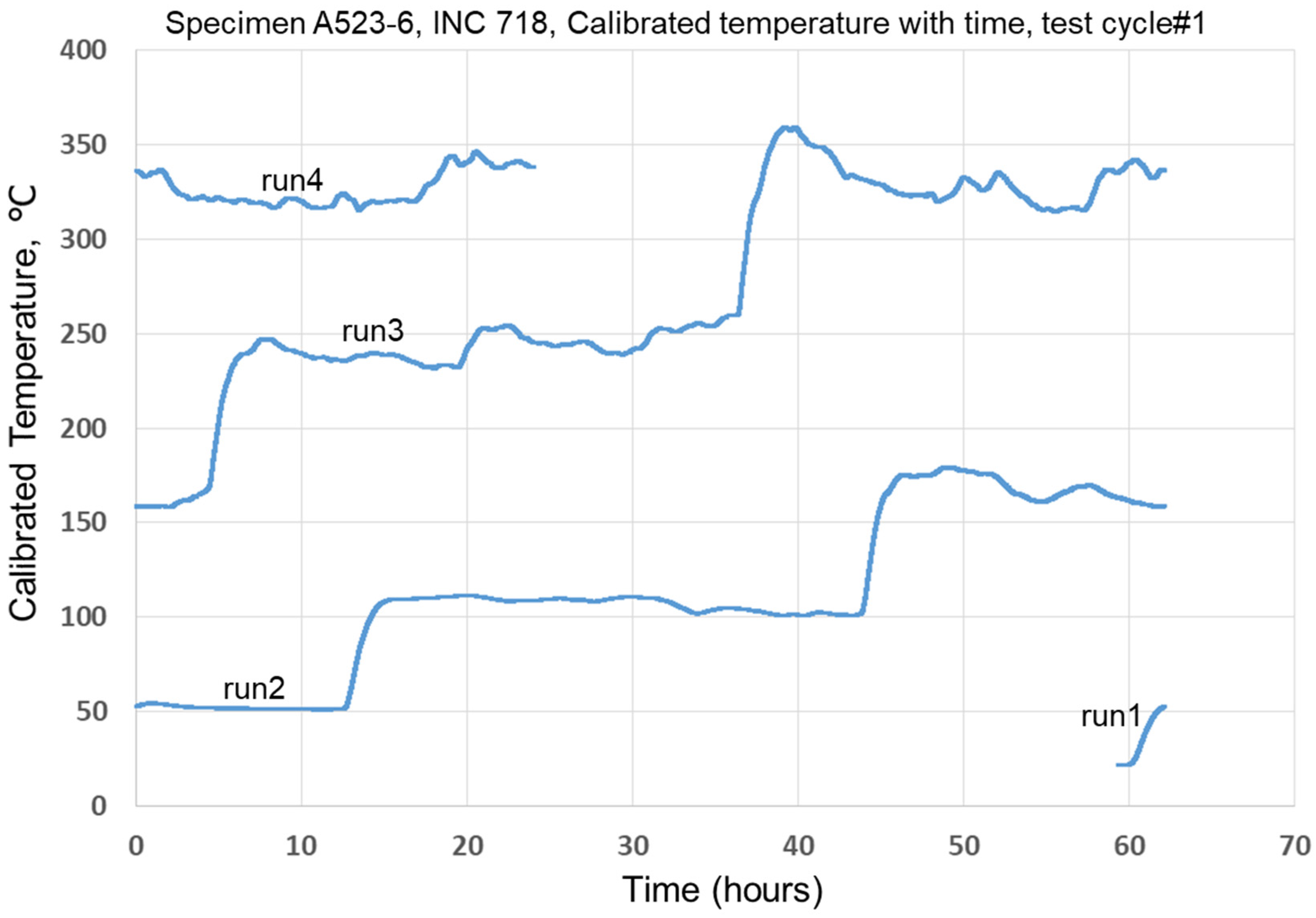
Figure 13, the sensor stability was impaired during run 3 while operating at around 700 °C due to temporary loss of signal strength. Another specimen, A523-6, INC 718 with embedded FBG sensor, was subjected to thermal cycling testing as shown in
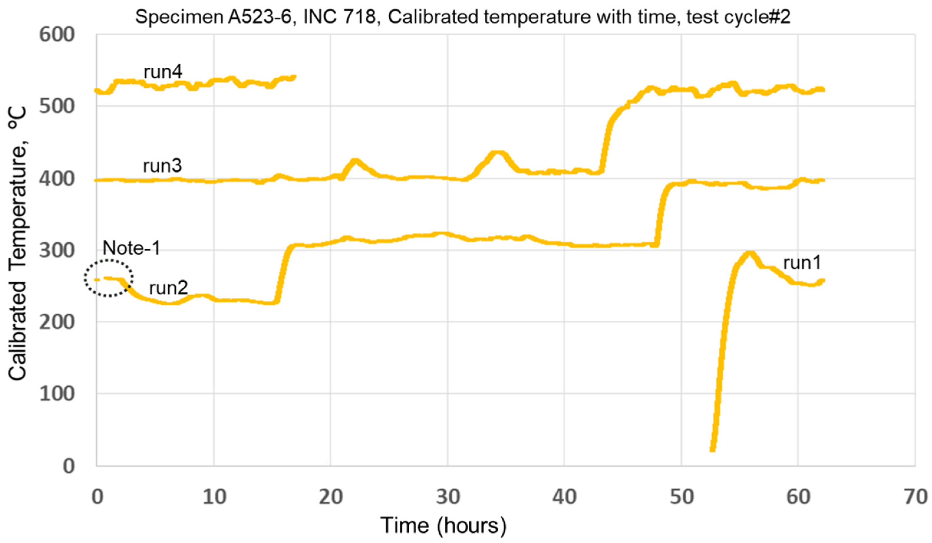
Figure 14 in the first test cycle (test cycle#1). After the prolonged testing continuously for about 2+ days, the thermal cycling test was then repeated on the same specimen embedded with the sensor as per the thermal cycling testing (test cycle#2) as shown in
Figure 15. At these temperatures, the FBG sensor seems to perform reasonably well capturing drifting temperatures caused by the furnace controller and heat loss from the furnace. Additionally the base material Inconel 718 microstructure is affected by the temporal length of exposure and thermal temperatures above 600. The phase change from γ to γ’ and γ’’ will affect the sensor responses. At lower temperatures, creep (prolonged exposure) may cause the sensor drifts. At higher temperatures of 600 °C and higher, the drift effect is pronounced from both the temperature and the duration of the exposure from creep.
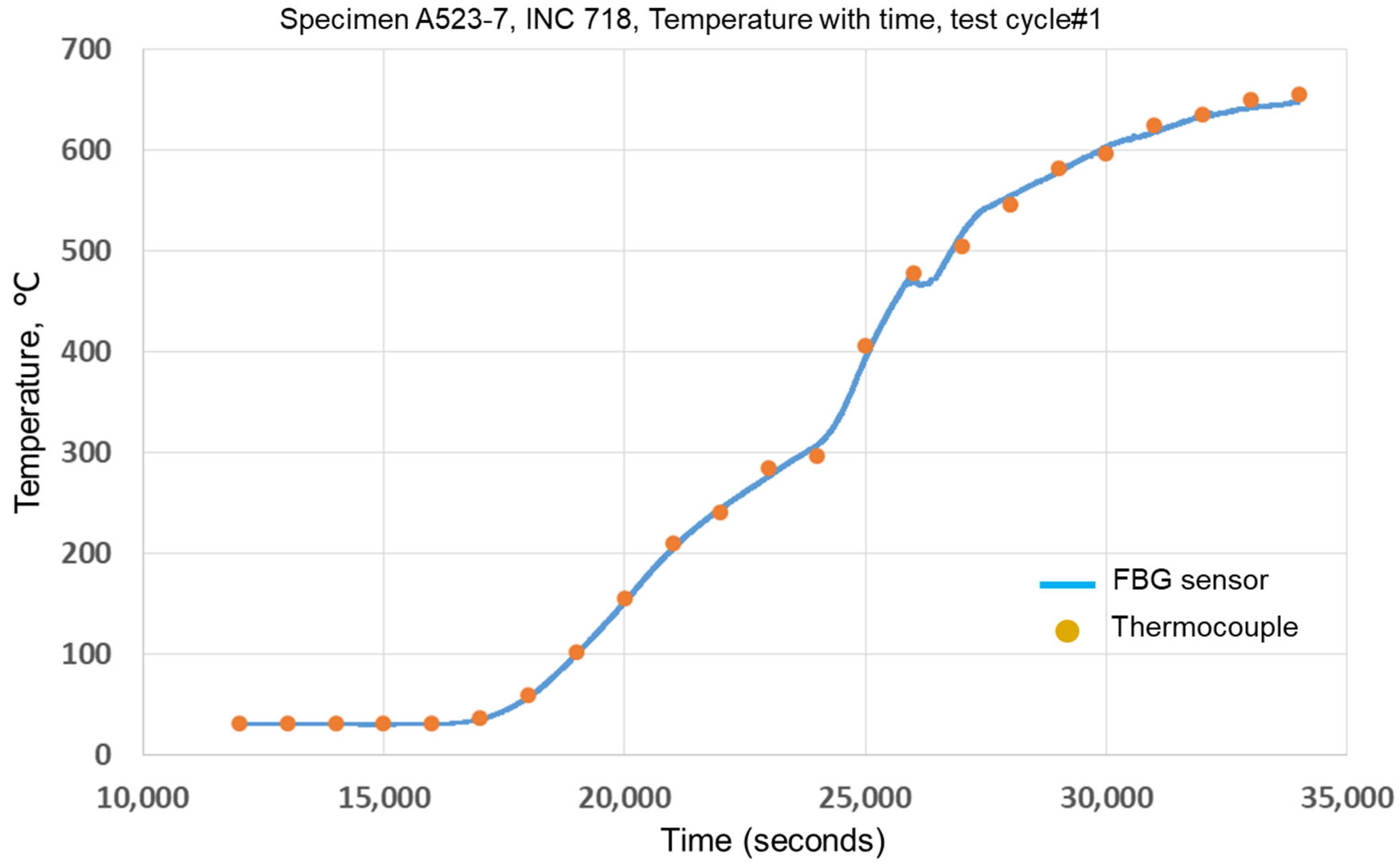
A different specimen, A523-7, INC 718 with the embedded sensor, was subjected to gradually increasing temperature testing (test cycle#1) as shown in
Figure 16. The acquired temperature measurements from the thermocouple are also plotted in
Figure 16 to show the comparison between the readings from the embedded FBG sensor and the thermocouple. As shown in
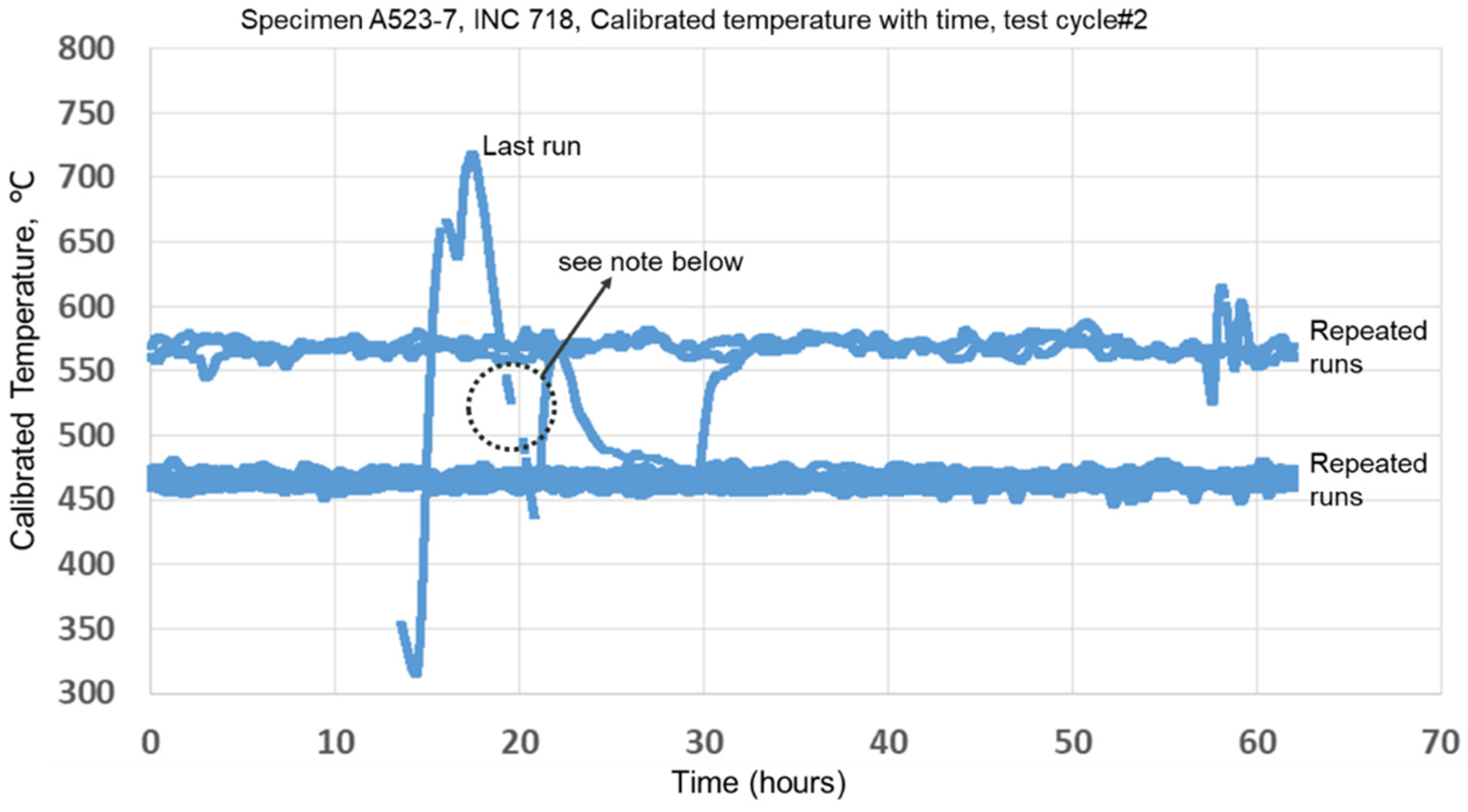
Figure 16, the FBG sensor was in good agreement with thermocouple data within a maximum of ±1.5% error. The same specimen was then subjected to nearly constant temperature testing conditions (multiple runs) as well as rapidly changing temperature conditions (test cycle#2) as shown in
Figure 17. During the test cycle#2 for INC 718 specimen A523-7 (shown in
Figure 17), there was a slight water leakage coming out of the water-cooled specimen grip fixture (on the TMF test rig), and water was found dripping along the specimen from the top down. Due to this, the furnace closed-loop controller constantly adjusted the heating to the set temperature level. Because of persistent temperature adjustments, the temperature data is quite wavy as shown in
Figure 17. Although this was not intended in the testing, this actually demonstrated the sensitivity of the sensor while operating under unsteady temperature conditions during rapid heating or cooling of a turbine blade during engine startup/shutdown or during on/off or intermittent blade film cooling conditions. However, in the last run (as shown in
Figure 17), when the specimen was rapidly taken to a temperature of slightly above 700 °C and then brought down quickly, there was loss of data caused by impaired signal strength which in turn shows that the FBGs start to erase.
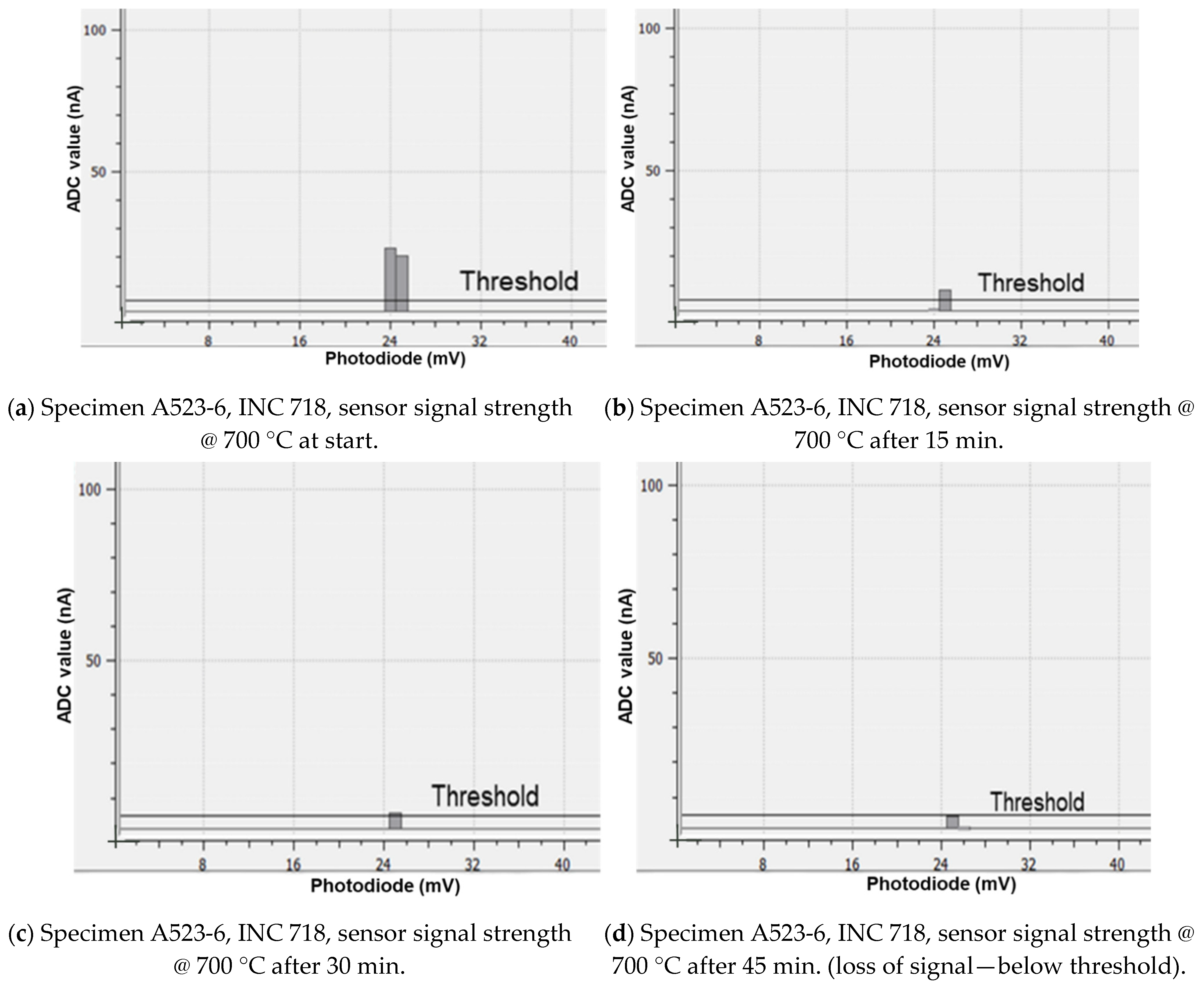
The
Figure 18a–d show the sensor stability during prolonged operation at high temperatures close to the maximum limit temperature of the FBG sensor. The signal strength variations from the specimen A523-6, INC 718 that was subjected to a constant temperature testing condition of ~700 °C are shown from start to an elapsed time of 45 min in steps of 15 min. intervals sequentially in the
Figure 18a–d. The
Figure 18a–d clearly show that the sensor fails over prolonged duration while operating near the limit of high temperature conditions. In summary, overall the FBG sensors survived the thermal cycling durability tests within their capable operating temperature limits, but at high temperature limits, the stability and reliability of the sensor become impaired during a long-duration operation. The sensing sensitivity response and accuracy during temperature variations were found to be reasonably good within the operating temperature limits.
5. Conclusions and Path Forward
In situ sensors on gas turbine engine components help to actively monitor engine components for extended seamless operation and improved reliability. Under this U.S. Army Foreign Technology Assessment Support (FTAS) program funded research project, embedded FBG sensors from Epsilon Optics Ltd. (U.K based company) were evaluated to measure temperature responses on typical turbine engine component material specimens. Overall, the embedded FBG sensors survived the cyclic temperature conditions. The sensitivity response and stability were assessed in long-duration thermal cycling durability tests continuously, with ramping up and down temperature conditions. Although, the embedded FBG sensor technology survived up to a maximum temperature condition of ~700 °C, continued stability and response were impaired during long-duration testing. However, much below 700 °C, the FBG sensors evaluated in this research demonstrated reasonably reliable operation, subject to other influencing factors such as material phase changes, glass annealing, etc. The experimental results confirmed the viability of using in-situ sensor in gas turbine engine components operating under harsh cyclic thermal conditions as compared to traditional current technology measurement devices that are intrusive and cannot be used on gas turbine engine components due to narrow flow passages and their detrimental aerodynamic effects on the flow field through these turbine engine components. However, additional sensor maturation is needed along with innovative component design concepts and manufacturing methods to elevate the technology readiness level. Proper protective shielding for the fiber-optic leads together with a wireless transmitter for rotating blades in real engine installations should also be developed.
This research investigation has led to the development efforts in separate related SBIR (small business innovative research) projects on embedded sensors for high temperature gas turbine engine component applications. The development and assessment of embedded sensors with the ongoing SBIR projects on this related research will enable transition of this emerging in situ, non-intrusive sensor capability in the U.S. Army’s future vertical lift propulsion systems in the near future. The sensor technologies being developed through SBIR projects will be evaluated under gas turbine engine relevant conditions in the near future.
