
A Novel Co-Phase Power Supply System for Electrified Railway Based on V Type Connection Traction Transformer


Abstract
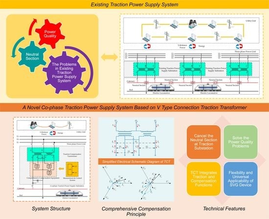
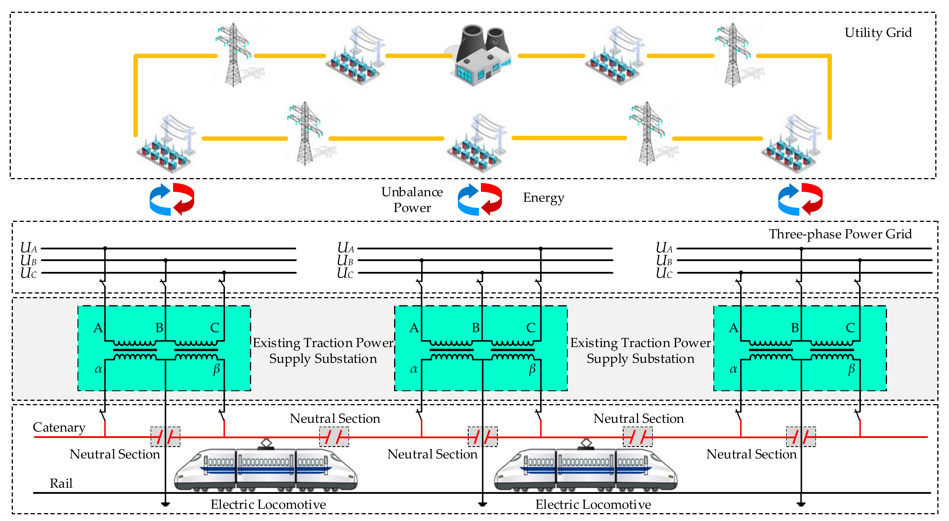
1. Introduction
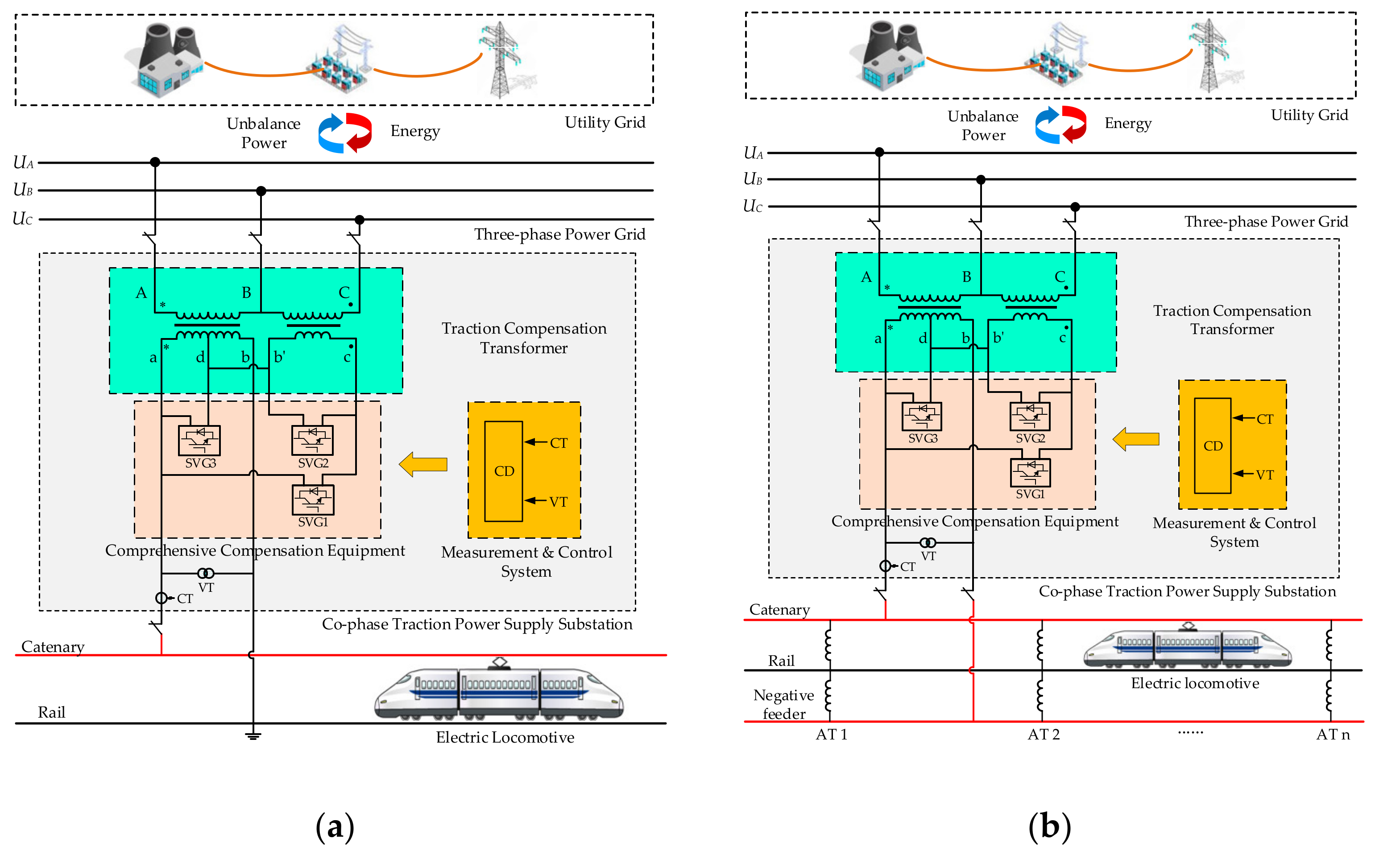
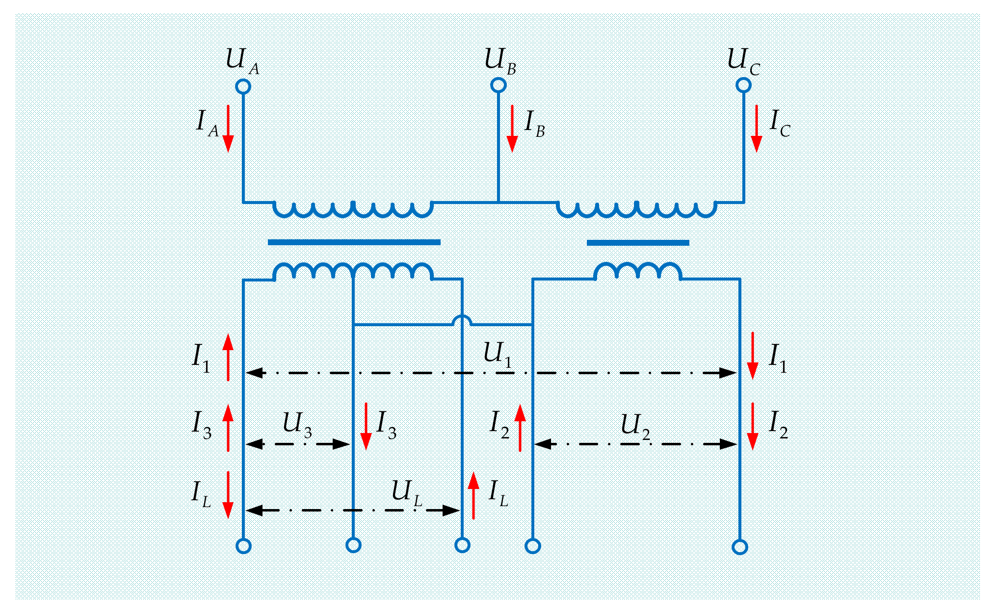
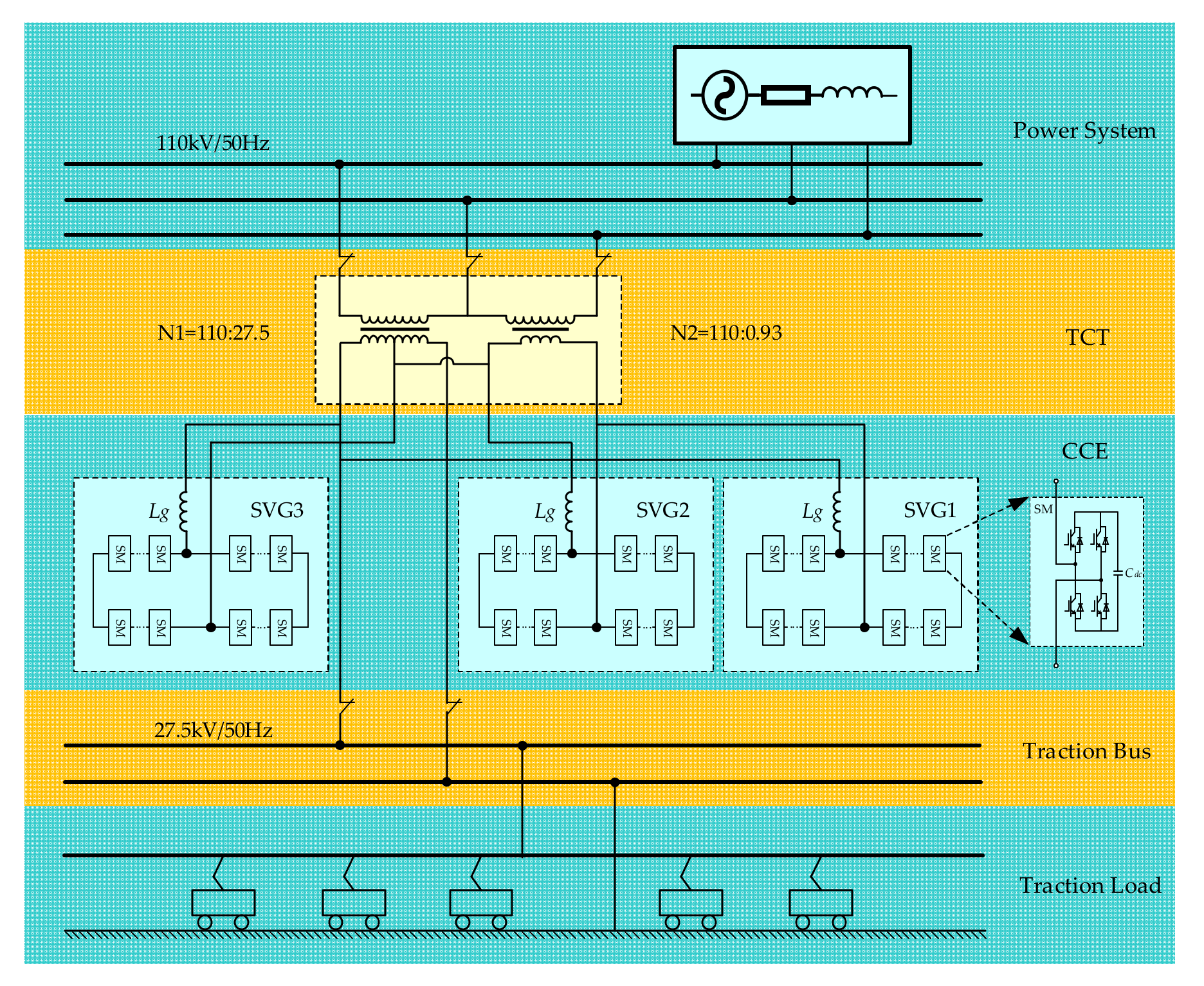
2. System Structure
3. Comprehensive Compensation Principle
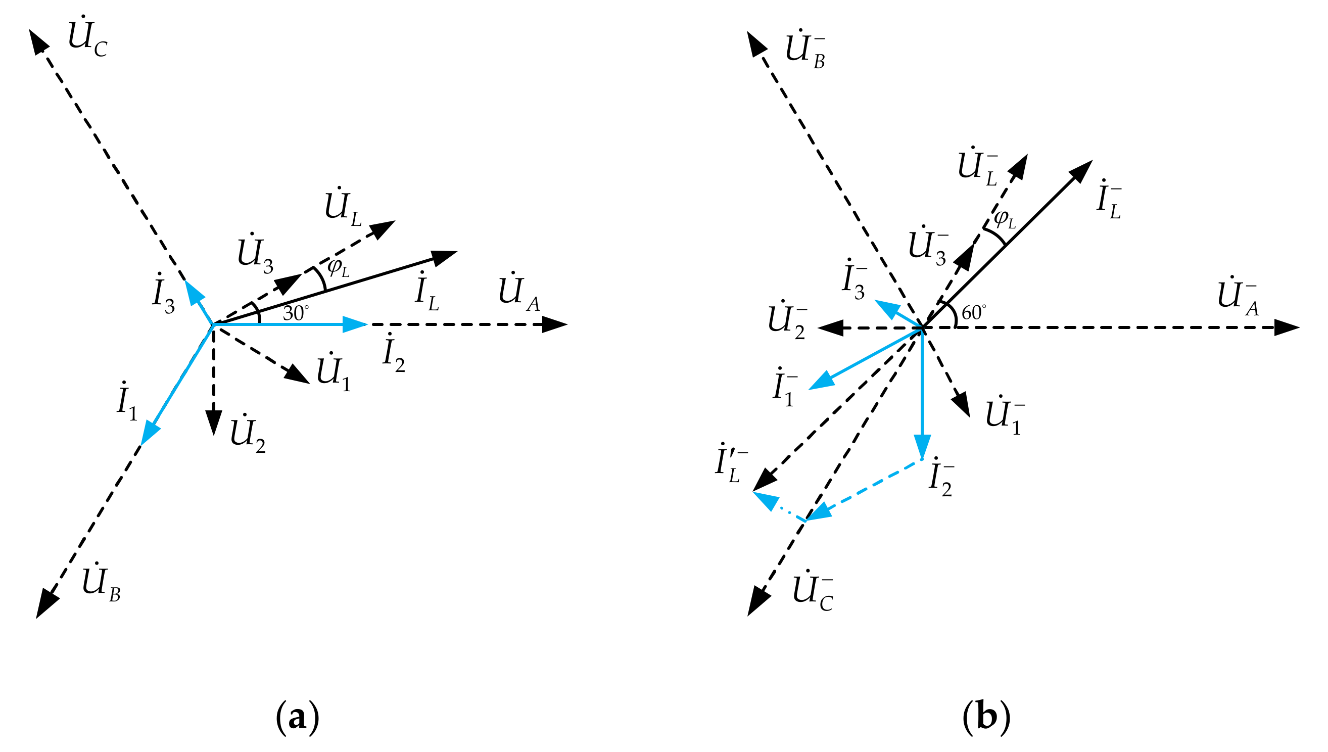
3.1. Comprehensive Compensation Principle
3.2. Comprehensive Compensation Model
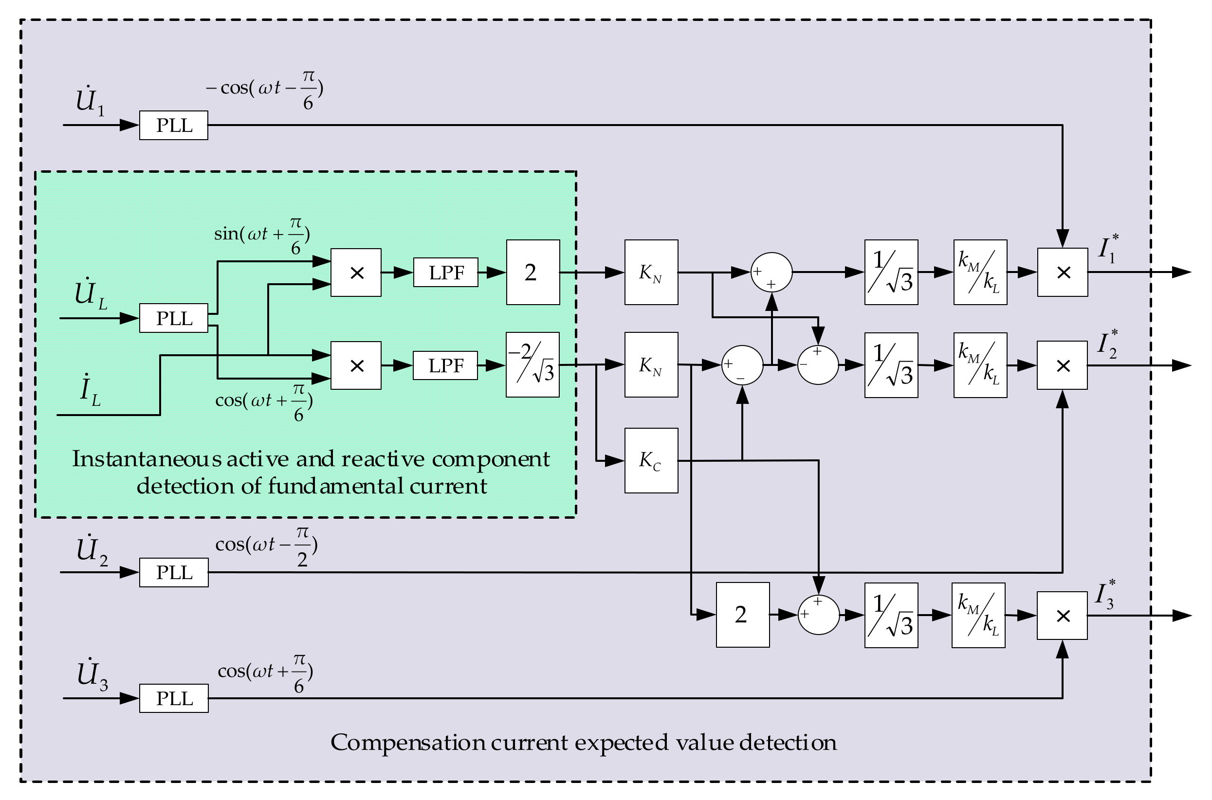
4. Comprehensive Compensation Control Strategy
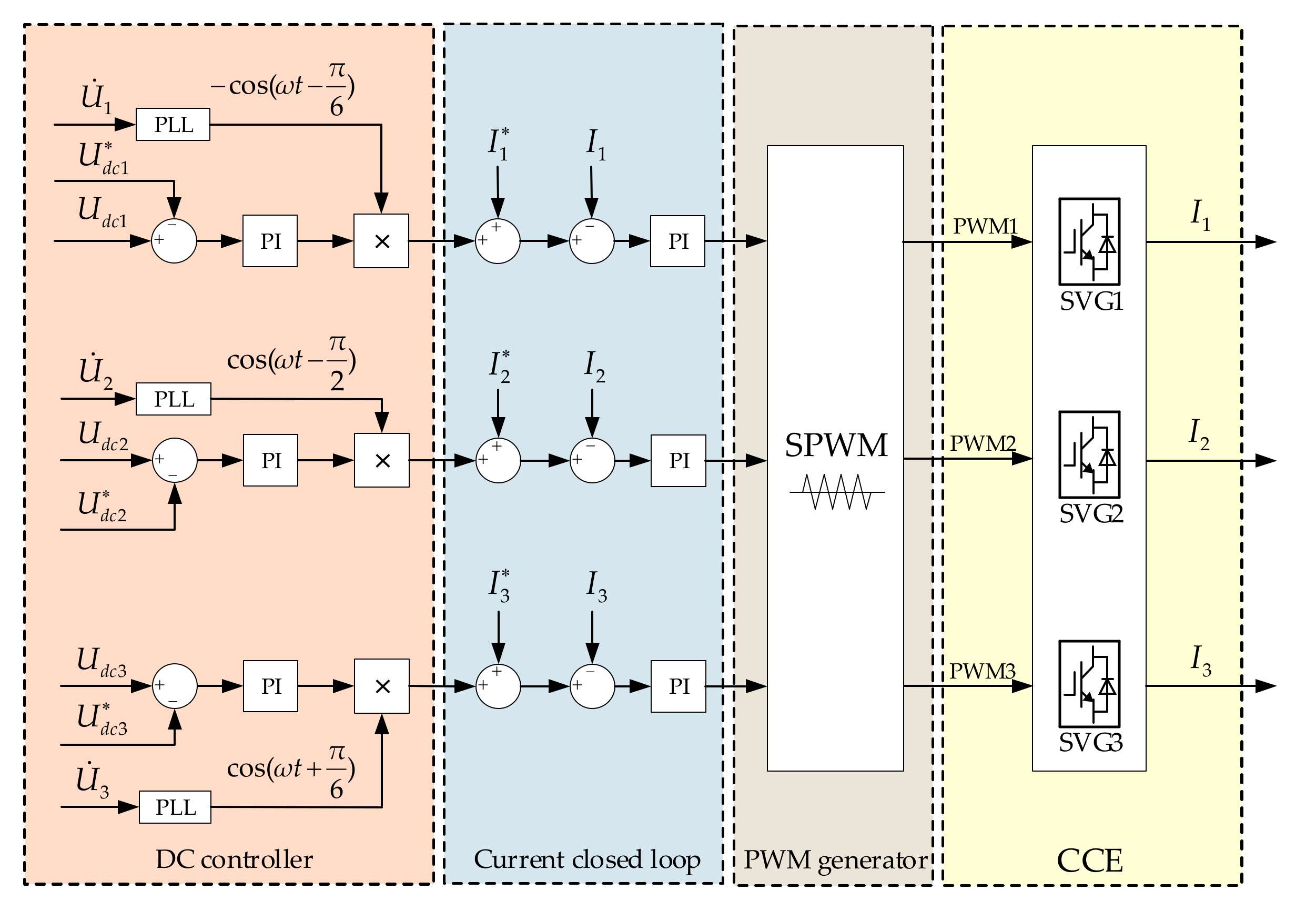
4.1. System Control Strategy
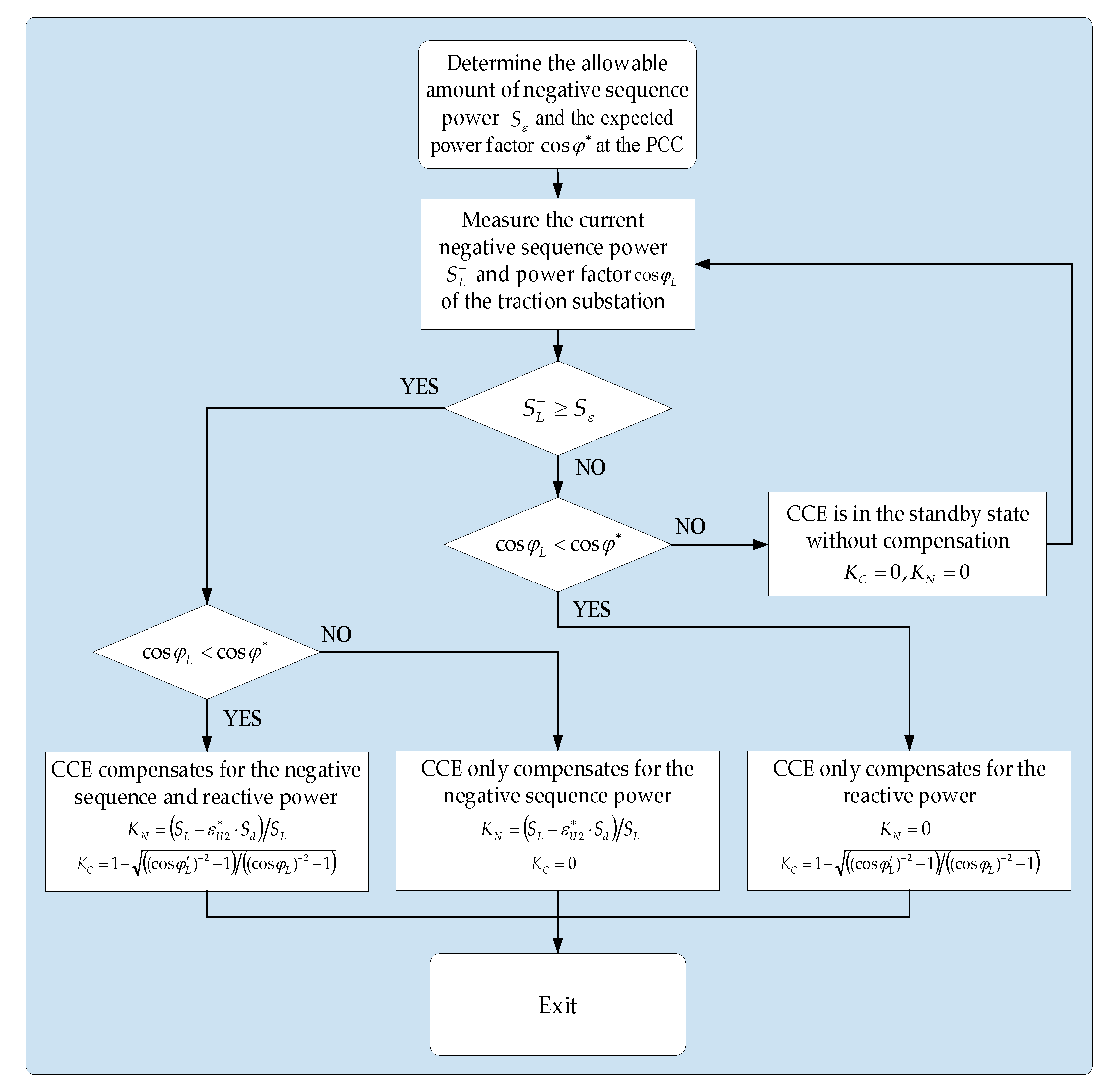
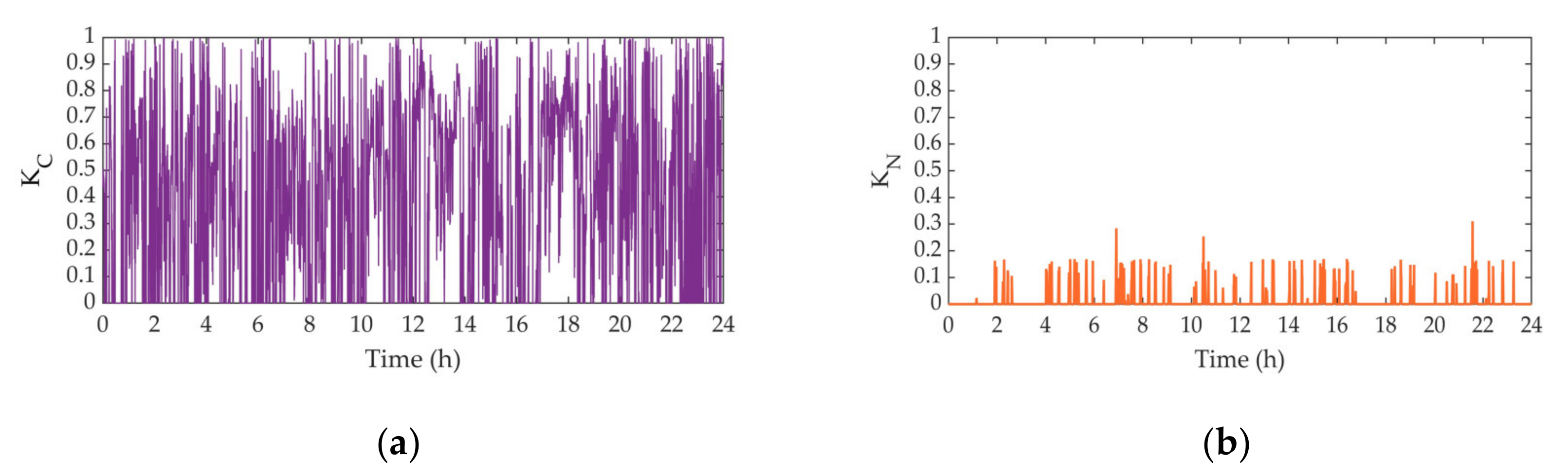
4.2. Determination Method and Steps of KC and KN
- (1)
- When the negative sequence power generated by the traction load is greater than the allowable negative sequence power at PCC, and the power factor is less than the target power factor value , the negative sequence and reactive power are compensated by CCE at the same time. Based on the expected target, the value of and can be determined according to Equations (18) and (20). Then, according to Equation (10), the , , and are obtained. Under the traction condition of traction load, is inductive or capacitive reactive ( or ), is capacitive or inductive reactive ( or ), and is capacitive reactive;
- (2)
- When is greater than , and is greater than or equal to . Only the negative sequence power is compensated by CCE, and the power factor is not changed before and after compensation. Therefore, can be determined by , and based on the expected target after compensation, the value of can be determined according to Equation (20). Then according to Equation (10), the , , and are obtained. Under the traction condition of traction load, is inductive reactive, and are capacitive reactive;
- (3)
- When is less than or equal to , and is less than . Only the reactive sequence power is compensated by CCE. Therefore, can be determined by , and based on the expected target after compensation, the value of can be determined according to Equation (18). Then, according to Equation (10), the , , and are obtained. Under the traction condition of traction load, , , and are all capacitive reactive;
- (4)
- When is less than or equal to , and is greater than or equal to . The negative sequence and reactive power generated by the traction load can meet the compensation target, no additional compensation is required. Therefore, and can be determined by and . CCE operates in standby.
5. Effectiveness Verification
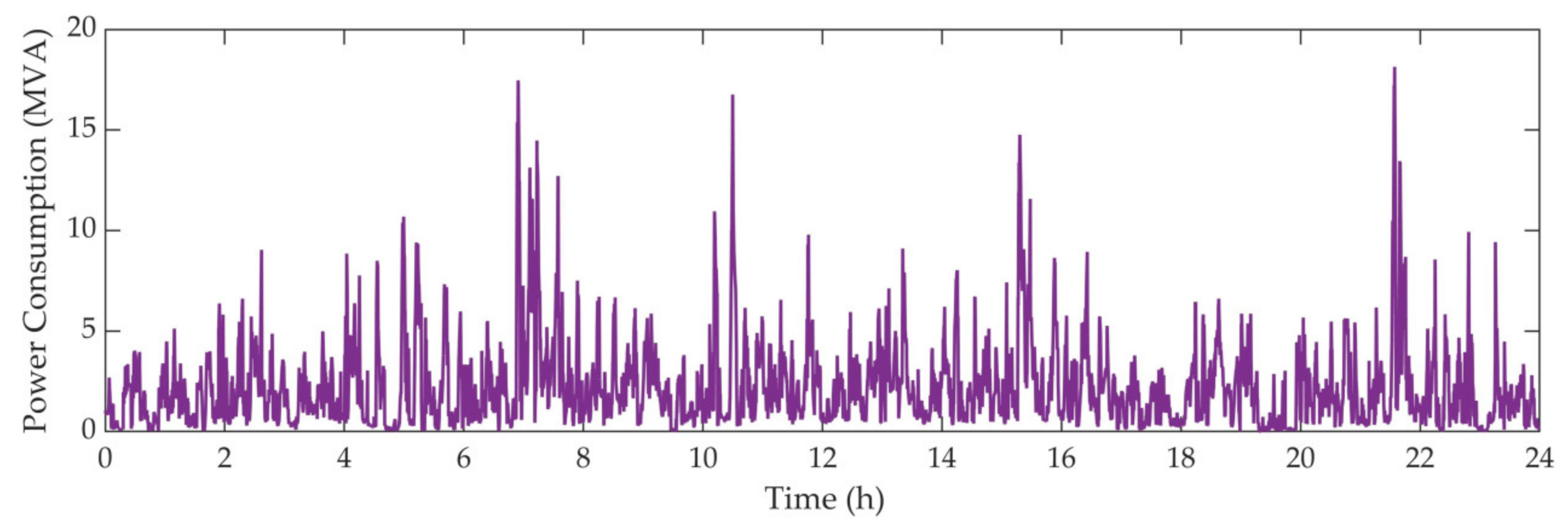
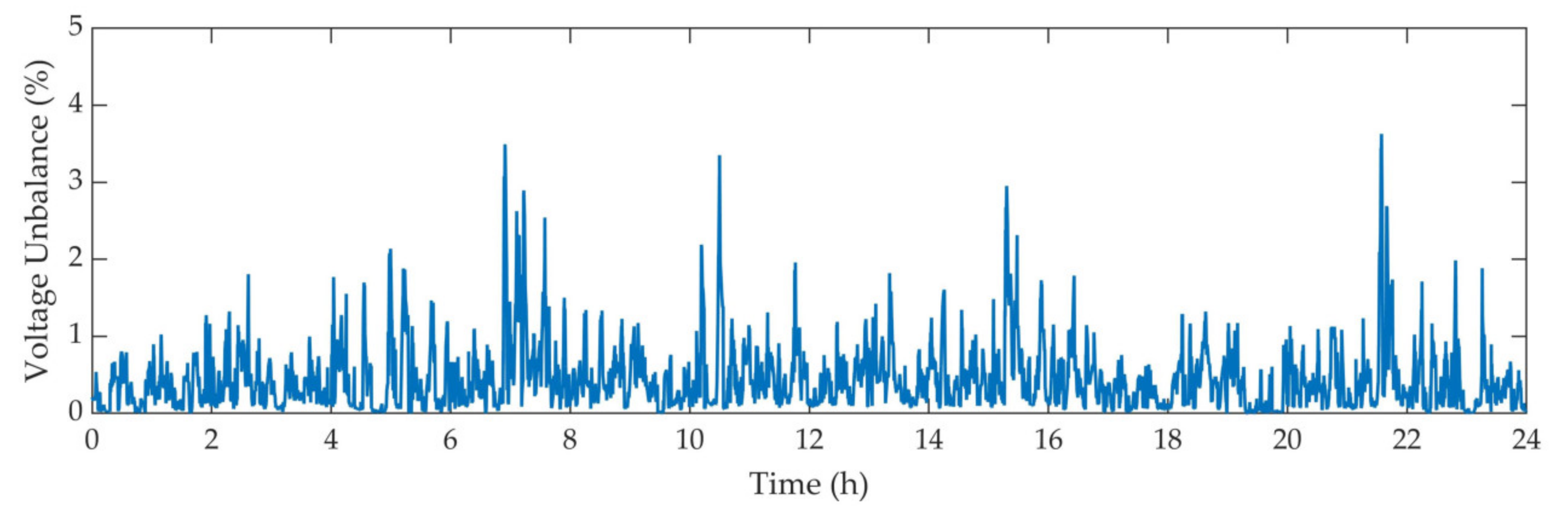
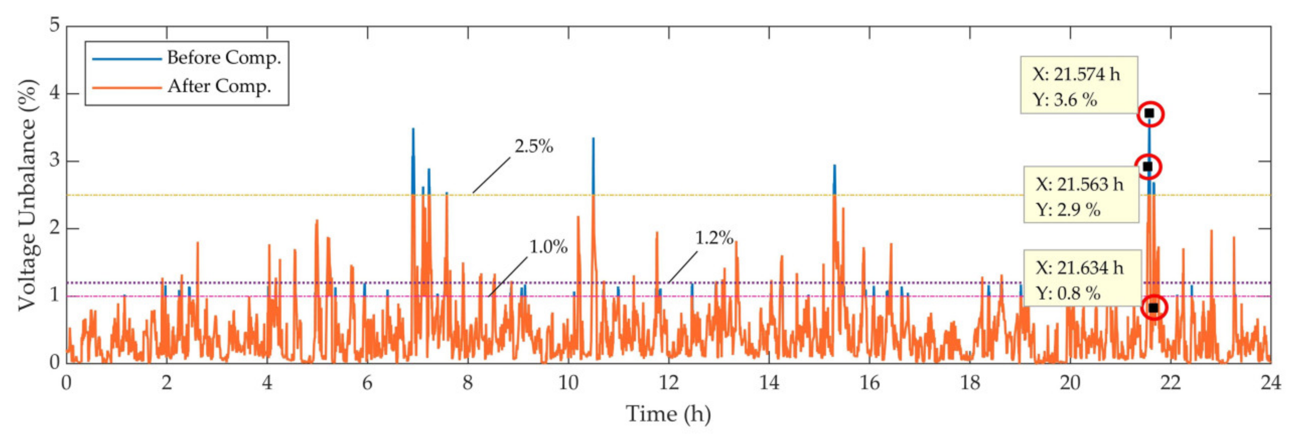
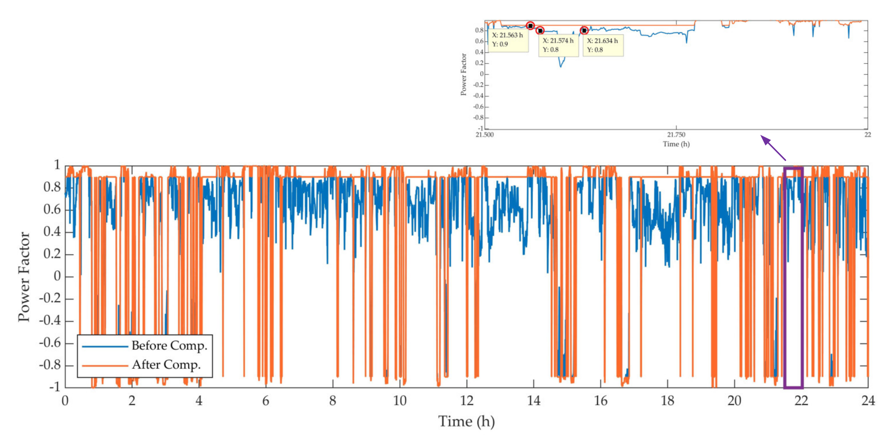
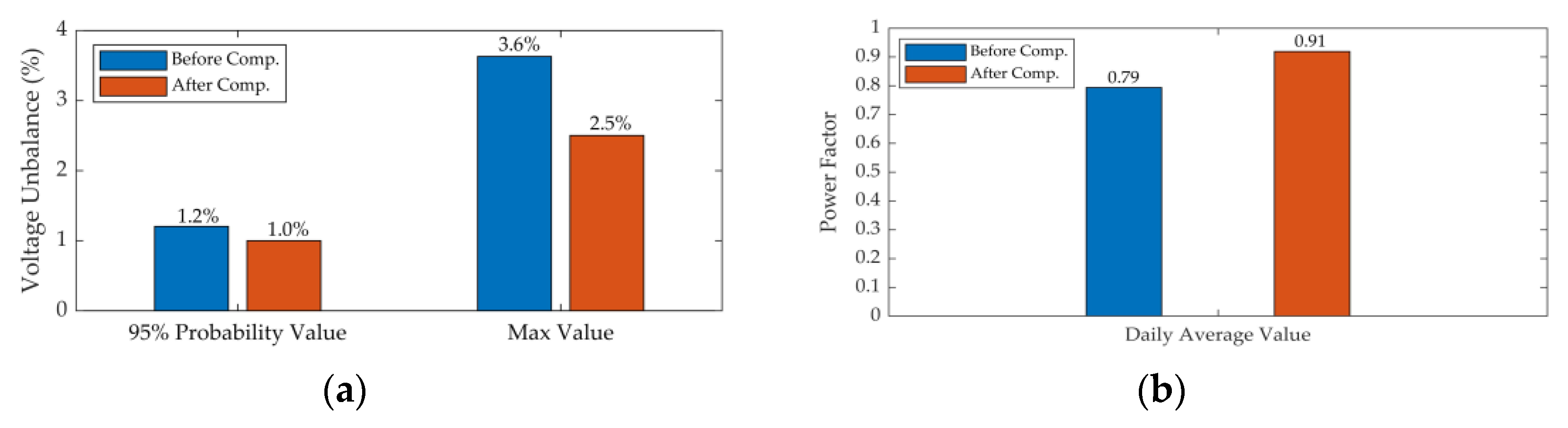
5.1. Analysis and Verification of Comprehensive Compensation Scheme Based on Actual Case
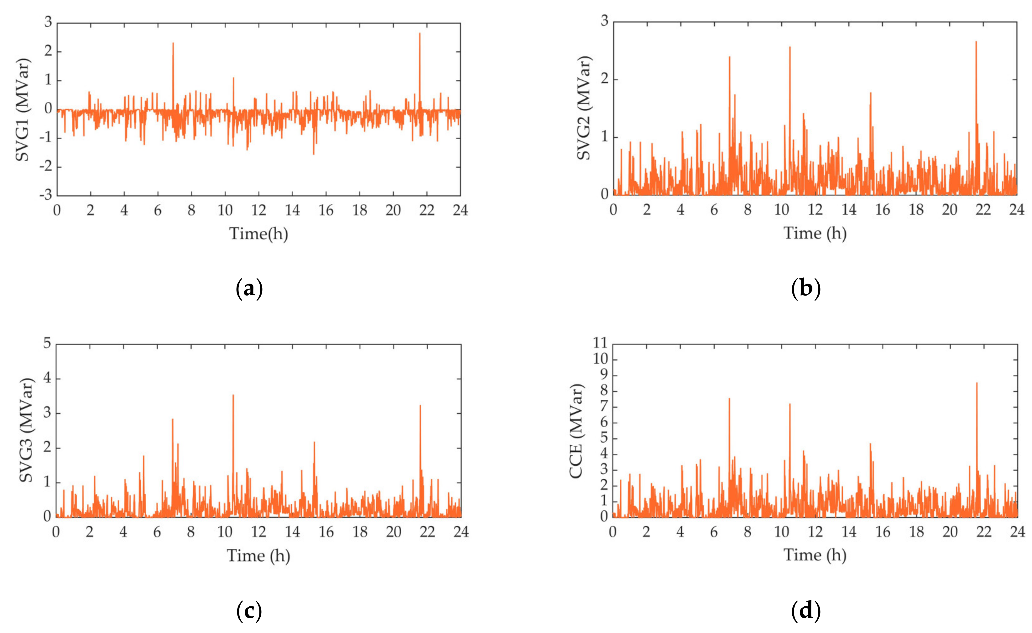
5.2. Analysis and Verification of Comprehensive Compensation Control Strategy
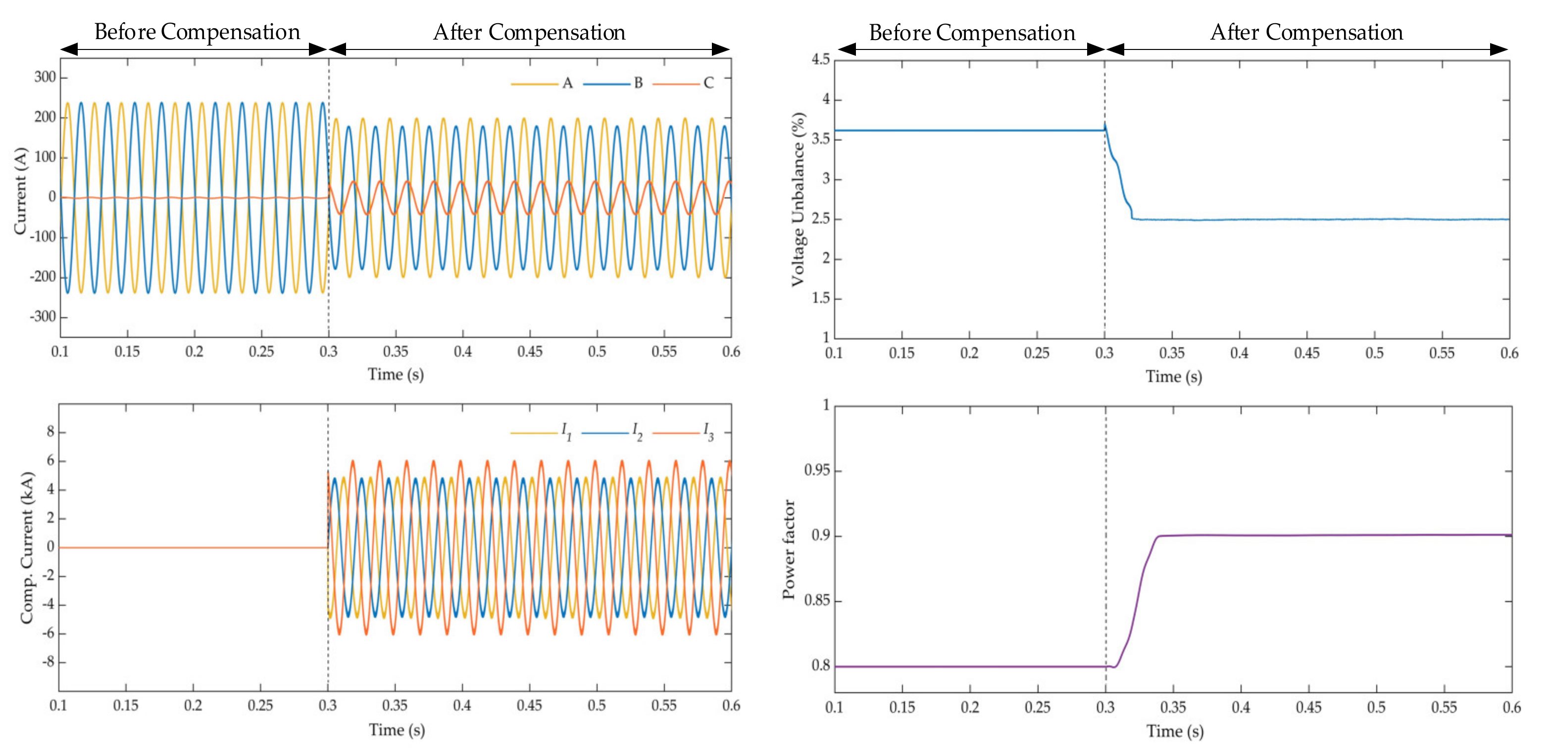
- Case 1:
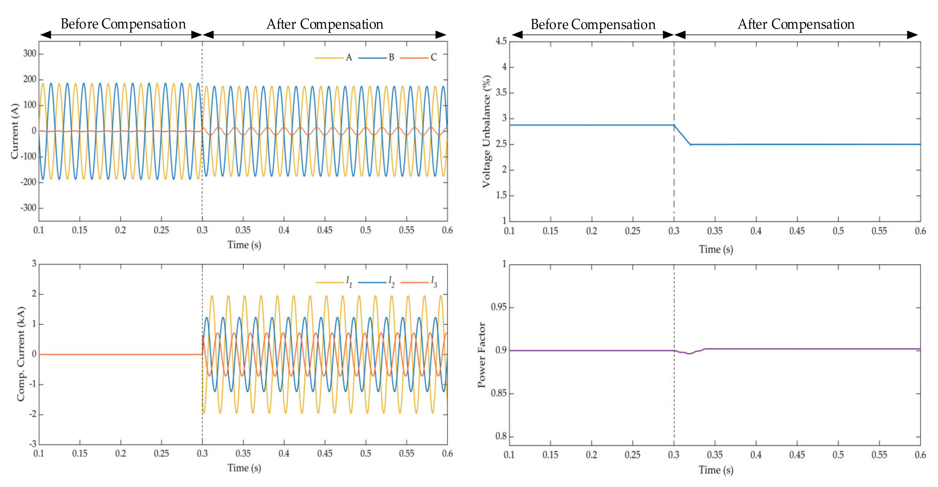
- Case 2:
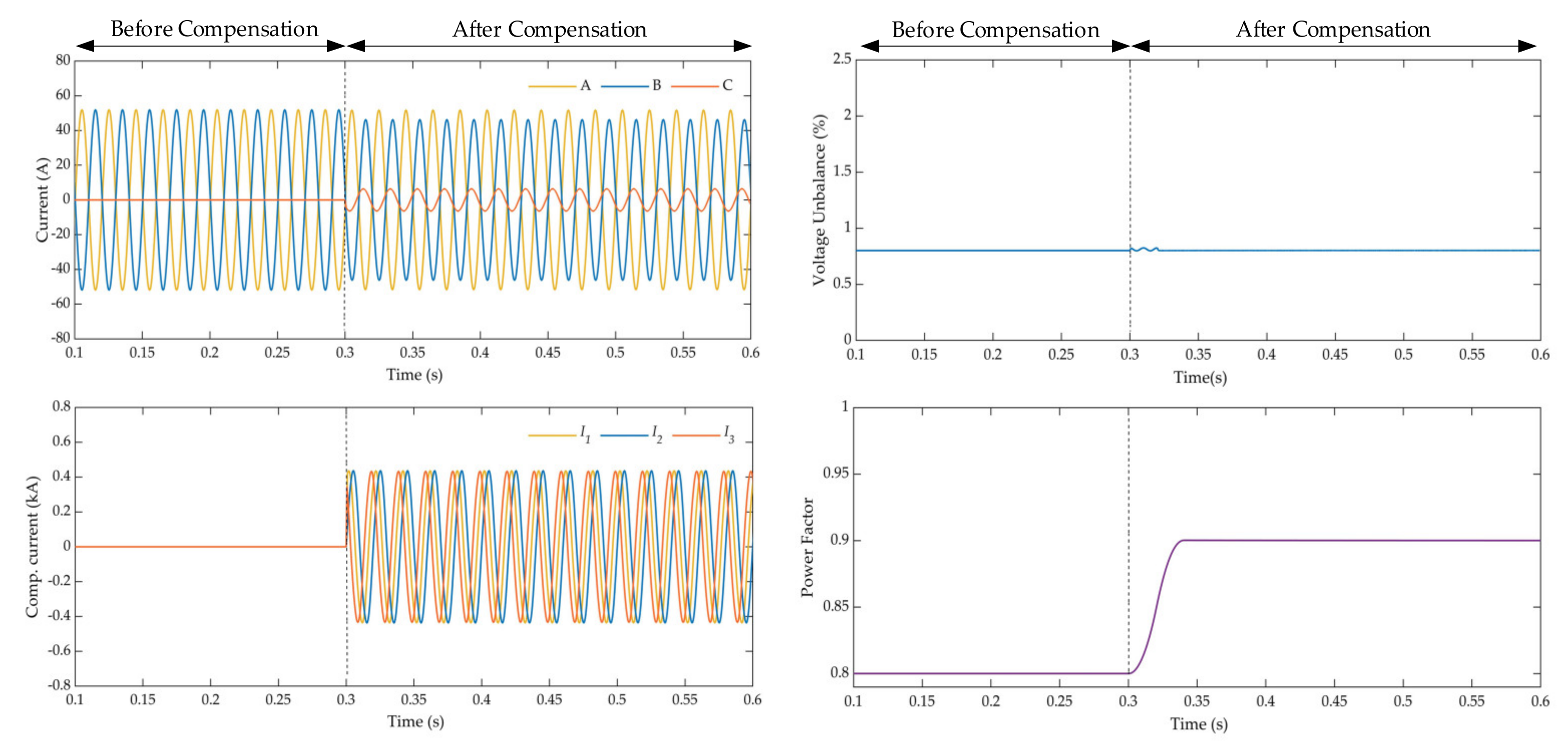
- Case 3:
6. Conclusions
Author Contributions
Funding
Institutional Review Board Statement
Informed Consent Statement
Data Availability Statement
Conflicts of Interest
Nomenclature
| Abbreviations | |
| SVG | Static Var Generator |
| PCC | Point of Common Coupling |
| RPC | Railway Static Power Conditioner |
| PFC | Power Flow Controller |
| HPQC | Hybrid Power Quality Conditioner |
| MMC | Modular Multilevel Converter |
| SVC | Static Var Compensator |
| TCT | Traction Compensation Transformer |
| CCE | Comprehensive Compensation Equipment |
| MCS | Measurement and Control System |
| VT | Voltage Transformer |
| CT | Current Transformer |
| CD | Controller Device |
| AT | Auto Transformer |
| Variables | |
| ,, | Voltage of the three-phase high-voltage bus |
| ,, | Negative sequence component of , , |
| , , | Compensation port voltage of TCT secondary side SVG1, SVG2, SVG3 |
| , , | Negative sequence component of ,, |
| ,, | Compensation current generated by SVG1, SVG2, SVG3 |
| , , | Negative sequence component of ,, |
| Traction port voltage of TCT secondary side | |
| Negative sequence component of | |
| Traction load current | |
| Negative sequence component of | |
| Reactive power of co-phase power supply traction substation after compensation | |
| Power factor of co-phase power supply traction substation after compensation | |
| Total apparent power of traction load | |
| Power factor angle of traction load | |
| Reactive power generated by SVGs | |
| Power factor angle of SVGs | |
| The number of compensation ports | |
| Reactive power compensation degree | |
| Angle of lagging behind | |
| Angle of compensating port k voltage lagging behind | |
| Negative sequence compensation degree | |
| ,, | Reactive power generated by SVG1, SVG2, SVG3 |
| TCT traction port voltage and primary sideline voltage transformation ratio | |
| TCT compensation port voltage and primary sideline voltage transformation ratio | |
| The effective value of fundamental current of traction load | |
| Power factor angle of fundamental current of traction load | |
| , | Instantaneous active component andreactive component of |
| ,, | Expected values of compensation current of SVG1, SVG2, and SVG3 |
| The limit of three-phase voltage unbalance degree at PCC | |
| The allowable negative sequence power at PCC | |
| The short circuit capacity at PCC | |
| The residual negative sequence power at PCC after compensation | |
| Expected value of three-phase voltage unbalance degree at PCC | |
| Expected value of power factor | |
References
- Chen, M.; Chen, Y.; Wei, M. Modeling and Control of a Novel Hybrid Power Quality Compensation System for 25-kV Electrified Railway. Energies 2019, 12, 3303. [Google Scholar] [CrossRef]
- He, X.; Ren, H.; Lin, J.; Han, P.; Wang, Y.; Peng, X.; Shu, Z. Power Flow Analysis of the Advanced Co-Phase Traction Power Supply System. Energies 2019, 12, 754. [Google Scholar] [CrossRef]
- Railway Statistics Bulletin. 2019. Available online: http://www.gov.cn/xinwen/2020-04/30/content_5507767.htm (accessed on 29 April 2020).
- Femine, A.D.; Gallo, D.; Giordano, D.; Landi, C.; Luiso, M.; Signorino, D. Power Quality Assessment in Railway Traction Supply Systems. IEEE Trans. Instrum. Meas. 2020, 69, 2355–2366. [Google Scholar] [CrossRef]
- Chen, Y.; Chen, M.; Tian, Z.; Liu, Y.; Hillmansen, S. VU limit pre-assessment for high-speed railway considering a grid connection scheme. IET Gener. Transm. Distrib. 2019, 13, 1121–1131. [Google Scholar] [CrossRef]
- Fang, L.; Xu, X.; Fang, H.; Xiao, Y. Negative-sequence current compensation of power quality compensator for high-speed electric railway. In Proceedings of the 2014 IEEE Conference and Expo Transportation Electrification Asia-Pacific (ITEC Asia-Pacific), Beijing, China, 31 August–3 September 2014; pp. 1–5. [Google Scholar]
- Tian, X.; Li, X.; Zhou, Z. Novel Uninterruptible Phase-Separation Passing and Power Quality Compensation Scheme Based on Modular Multilevel Converter for Double-Track Electrified Railway. Energies 2020, 13, 738. [Google Scholar] [CrossRef]
- Wu, C.; Luo, A.; Shen, J.; Ma, F.; Peng, S. A Negative Sequence Compensation Method Based on a Two-Phase Three-Wire Converter for a High-Speed Railway Traction Power Supply System. IEEE Trans. Power Electron. 2012, 27, 706–717. [Google Scholar] [CrossRef]
- He, X.; Shu, Z.; Peng, X.; Zhou, Q.; Zhou, Y.; Zhou, Q.; Gao, S. Advanced Cophase Traction Power Supply System Based on Three-Phase to Single-Phase Converter. IEEE Trans. Power Electron. 2014, 29, 5323–5333. [Google Scholar] [CrossRef]
- Zhou, Y.; Guo, A.; He, X. Output-transformerless traction substation based on three-phase to single-phase cascaded converter. In Proceedings of the 2014 International Power Electronics and Application Conference and Exposition, Shanghai, China, 5–8 November 2014; pp. 749–753. [Google Scholar]
- Min, J.; Ma, F.; Xu, Q.; He, Z.; Luo, A.; Spina, A. Analysis, Design, and Implementation of Passivity-Based Control for Multilevel Railway Power Conditioner. IEEE Trans. Ind. Inf. 2018, 14, 415–425. [Google Scholar] [CrossRef]
- Luo, A.; Ma, F.; Wu, C.; Ding, S.; Zhong, Q.; Shuai, Z. A Dual-Loop Control Strategy of Railway Static Power Regulator Under V/V Electric Traction System. IEEE Trans. Power Electron. 2011, 26, 2079–2091. [Google Scholar] [CrossRef]
- Zhang, D.; Zhang, Z.; Wang, W.; Yang, Y. Negative Sequence Current Optimizing Control Based on Railway Static Power Conditioner in V/v Traction Power Supply System. IEEE Trans. Power Electron. 2016, 31, 200–212. [Google Scholar] [CrossRef]
- Ma, F.; Xu, Q.; He, Z.; Tu, C.; Shuai, Z.; Lou, A.; Li, Y. A Railway Traction Power Conditioner Using Modular Multilevel Converter and Its Control Strategy for High-Speed Railway System. IEEE Trans. Transp. Electr. 2016, 2, 96–109. [Google Scholar] [CrossRef]
- Chen, M.; Liu, R.; Xie, S.; Zhang, X.; Zhou, Y. Modeling and Simulation of Novel Railway Power Supply System Based on Power Conversion Technology. In Proceedings of the 2018 International Power Electronics Conference (IPEC-Niigata 2018-ECCE Asia), Niigata, Japan, 20–24 May 2018; pp. 2547–2551. [Google Scholar]
- Zhu, X.; Chen, M.; Xie, S.; Luo, J. Research on new traction power system using power flow controller and Vx connection transformer. In Proceedings of the 2016 IEEE International Conference on Intelligent Rail Transportation (ICIRT), Birmingham, UK, 23–25 August 2016; pp. 111–115. [Google Scholar]
- Kaleybar, H.J.; Brenna, M.; Foiadelli, F.; Fazel, S.S. Regenerative Braking Energy and Power Quality Analysis in 2 × 25 kV High-Speed Railway Lines Operating with 4QC Locomotives. In Proceedings of the 2020 11th Power Electronic and Drive Systems and Technologies Conference (PEDSTC), Tehran, Iran, 4–6 February 2020; pp. 1–6. [Google Scholar]
- Mariscotti, A. Behaviour of Spectral Active Power Terms for the Swiss 15 kV 16.7 Hz Railway System. In Proceedings of the 2019 IEEE 10th International Workshop on Applied Measurements for Power Systems (AMPS), Aachen, Germany, 25–27 September 2019; pp. 1–6. [Google Scholar]
- Li, Q. New generation traction power supply system and its key technologies for electrified railways. J. Mod. Transport. 2015, 23, 1–11. [Google Scholar] [CrossRef]
- Mochinaga, Y.; Hisamizu, Y.; Takeda, M.; Miyashita, T.; Hasuike, K. Static power conditioner using GTO converters for AC electric railway. In Proceedings of the Power Conversion Conference, Yokohama, Japan, 19–23 April 1993; pp. 641–646. [Google Scholar]
- Mochinaga, Y.; Uzuka, T. Development of Single Phase Feeding Power Conditioner for Shinkansen Depots. QR RTRI 2000, 41, 154–158. [Google Scholar] [CrossRef][Green Version]
- Morimoto, H.; Ando, M.; Mochinaga, Y.; Kato, T.; Yoshizawa, J.; Gomi, T.; Miyashita, T.; Funahashi, S.; Nishitoba, M.; Oozeki, S. Development of railway static power conditioner used at substation for Shinkansen. In Proceedings of the Power Conversion Conference, Osaka, Japan, 2–5 April 2002; pp. 1108–1111. [Google Scholar]
- Li, Q.; Zhang, J.; He, W. Research on a new power supply system suitable for heavy-duty electric traction. J. CRS 1988, 4, 23–31. (In Chinese) [Google Scholar]
- Li, Q. Unified traction power supply mode for trunk railway and urban rail transit. Sci. Sin. Tech. 2018, 48, 1179–1189. (In Chinese) [Google Scholar] [CrossRef]
- Li, Q. Several Key Technical Issues in the Development of Traction Power Supply for High-speed Railways in China. J. CRS 2010, 32, 119–124. (In Chinese) [Google Scholar]
- Shu, Z.; Xie, S.; Li, Q. Single-Phase Back-To-Back Converter for Active Power Balancing, Reactive Power Compensation, and Harmonic Filtering in Traction Power System. IEEE Trans. Power Electron. 2011, 26, 334–343. [Google Scholar] [CrossRef]
- Shu, Z.; Xie, S.; Lu, K.; Zhao, Y.; Nan, X.; Qiu, D.; Zhou, F.; Gao, S.; Li, Q. Digital Detection, Control, and Distribution System for Co-Phase Traction Power Supply Application. IEEE Trans. Ind. Electron. 2013, 60, 1831–1839. [Google Scholar] [CrossRef]
- He, X.; Guo, A.; Peng, X.; Zhou, Y.; Shi, Z.; Shu, Z. A Traction Three-Phase to Single-Phase Cascade Converter Substation in an Advanced Traction Power Supply System. Energies 2015, 8, 9915–9929. [Google Scholar] [CrossRef]
- Lao, K.; Wong, M.; Dai, N.Y.; Wong, C.; Lam, C. Analysis of DC-Link Operation Voltage of a Hybrid Railway Power Quality Conditioner and Its PQ Compensation Capability in High-Speed Cophase Traction Power Supply. IEEE Trans. Power Electron. 2016, 31, 1643–1656. [Google Scholar] [CrossRef]
- Habibolahzadeh, M.; Roudsari, H.M.; Jalilian, A.; Jamali, S. Improved Railway Static Power Conditioner Using C-type Filter in Scott Co-phase Traction Power Supply System. In Proceedings of the 2019 10th International Power Electronic and Drive Systems and Technologies Conference (PEDSTC), Shiraz, Iran, 12–14 February 2019; pp. 355–360. [Google Scholar]
- Vemulapati, V.; Vijayakumar, Y.N.; Visali, N. Droop Characteristics based High Speed Traction Power Supply system using Modular Multilevel Converter. In Proceedings of the 2020 4th International Conference on Trends in Electronics and Informatics (ICOEI), Tirunelveli, India, 15–17 June 2020; pp. 111–118. [Google Scholar]
- Vijaykumar, Y.N.; Vemulapati, V.; Visali, N.; Raju, K. Railway Power Supply System using Modular Multilevel Converter with Droop Characteristics. In Proceedings of the 2020 4th International Conference on Electronics, Communication and Aerospace Technology (ICECA), Coimbatore, India, 5–7 November 2020; pp. 12–20. [Google Scholar]
- AlBader, M.; Enjeti, P. Three phase to Co-phase railway electrification approach using voltage synthesizing electronic phase shifter (EPS). In Proceedings of the 2016 IEEE Transportation Electrification Conference and Expo (ITEC), Dearborn, MI, USA, 27–29 June 2016; pp. 1–4. [Google Scholar]
- Mousavi Gazafrudi, S.M.; Tabakhpour Langerudy, A.; Fuchs, E.F.; Al-Haddad, K. Power Quality Issues in Railway Electrification: A Comprehensive Perspective. IEEE Trans. Ind. Electron. 2015, 62, 3081–3090. [Google Scholar] [CrossRef]
- Omi, M.; Kotegawa, R.; Ando, M.; Masui, T.; Horita, Y. Introduction and effectiveness of STATCOM to the independent power system of JR East. In Proceedings of the 2014 International Power Electronics Conference (IPEC-Hiroshima 2014-ECCE ASIA), Hiroshima, Japan, 18–21 May 2014; pp. 1317–1321. [Google Scholar]
- Tamai, S. Novel power electronics application in traction power supply system in Japan. In Proceedings of the 2014 16th International Power Electronics and Motion Control Conference and Exposition, Antalya, Turkey, 21–24 September 2014; pp. 701–706. [Google Scholar]
- Luo, L.; Chen, P.; Cui, P.; Zhang, Z.; Zhou, Y.; Xie, X.; Chen, J. A current balance compensation method for traction substation based on SVG and V/v transformer. In Proceedings of the 2017 IEEE Transportation Electrification Conference and Expo, Asia-Pacific (ITEC Asia-Pacific), Harbin, China, 7–10 August 2017; pp. 1–6. [Google Scholar]
- Horita, Y.; Morishima, N.; Kai, M.; Onishi, M.; Masui, T.; Noguchi, M. Single-phase STATCOM for feeding system of Tokaido Shinkansen. In Proceedings of the 2010 International Power Electronics Conference-ECCE ASIA, Sapporo, Japan, 21–24 June 2010; pp. 2165–2170. [Google Scholar]
- Li, Q.; He, J. Analysis of Traction Power Supply System; Southwest Jiaotong University Press: Chengdu, China, 2012. [Google Scholar]
- Power Quality—Three-Phase Voltage Unbalance; National Standard of the People’s Republic of China GB/T 15543-2008; Standardization Administration of the People’s Republic of China: Beijing, China, 2008.


| Parameters | Three-Phase Voltage | Three-Phase Voltage Unbalance Degree | Power Factor | |
|---|---|---|---|---|
| Positive Sequence | Negative Sequence | |||
| Before compensation | 61.89 kV | 2.23 kV | 3.6% | 0.8 |
| After compensation | 62.28 kV | 1.56 kV | 2.5% | 0.9 |
| Parameters | Three-Phase Voltage | Three-Phase Voltage Unbalance Degree | Power Factor | |
|---|---|---|---|---|
| Positive Sequence | Negative Sequence | |||
| Before compensation | 62.48 kV | 1.80 kV | 2.9% | 0.9 |
| After compensation | 62.48 kV | 1.56 kV | 2.5% | 0.9 |
| Parameters | Three-Phase Voltage | Three-Phase Voltage Unbalance Degree | Power Factor | |
|---|---|---|---|---|
| Positive Sequence | Negative Sequence | |||
| Before compensation | 63.15 kV | 0.50 kV | 0.8% | 0.8 |
| After compensation | 63.26 kV | 0.51 kV | 0.8% | 0.9 |
Publisher’s Note: MDPI stays neutral with regard to jurisdictional claims in published maps and institutional affiliations. |
© 2021 by the authors. Licensee MDPI, Basel, Switzerland. This article is an open access article distributed under the terms and conditions of the Creative Commons Attribution (CC BY) license (http://creativecommons.org/licenses/by/4.0/).
Share and Cite
Xie, S.; Zhang, Y.; Wang, H. A Novel Co-Phase Power Supply System for Electrified Railway Based on V Type Connection Traction Transformer. Energies 2021, 14, 1214. https://doi.org/10.3390/en14041214
Xie S, Zhang Y, Wang H. A Novel Co-Phase Power Supply System for Electrified Railway Based on V Type Connection Traction Transformer. Energies. 2021; 14(4):1214. https://doi.org/10.3390/en14041214
Chicago/Turabian StyleXie, Shaofeng, Yiming Zhang, and Hui Wang. 2021. "A Novel Co-Phase Power Supply System for Electrified Railway Based on V Type Connection Traction Transformer" Energies 14, no. 4: 1214. https://doi.org/10.3390/en14041214
APA StyleXie, S., Zhang, Y., & Wang, H. (2021). A Novel Co-Phase Power Supply System for Electrified Railway Based on V Type Connection Traction Transformer. Energies, 14(4), 1214. https://doi.org/10.3390/en14041214