Article

Integrated Electric Vehicle Shunt Current Sensing System for Concurrent Revenue Metering and Detection of DC Injection †

1
Department of Electrical and Computer Engineering, University of Delaware, Newark, DE 19716, USA
2
College of Earth, Ocean and Environment, University of Delaware, Newark, DE 19716, USA
*
Author to whom correspondence should be addressed.
The manuscript is based upon the first author’s Ph.D. thesis, chapter 3.
Energies 2021, 14(4), 1193; https://doi.org/10.3390/en14041193
Submission received: 15 January 2021 / Revised: 15 February 2021 / Accepted: 19 February 2021 / Published: 23 February 2021
(This article belongs to the Special Issue Advanced Electric Vehicle Techniques)

Abstract

:
Certified electric vehicle power converters can inject DC current into the AC grid if they fail. Verification of DC injection by electric vehicle supply equipment can be a cost-effective extra measure to ensure power quality from a variety of plugged-in electric vehicles. As electric vehicle supply equipment typically performs high-accuracy revenue energy metering, we propose that measurement of AC current and DC injection with a single sensor is the most economically efficient design. This article presents an integrated shunt current sensing system with separation of AC and DC signals for concurrent revenue metering and DC injection detection. It also shows how the combined sensor is integrated into 19.2 kW single-phase electric vehicle supply equipment, and outlines how the design would be extended to 100 kW three-phase electric vehicle supply equipment. The prototype can detect DC injection of ≥400 mA in an AC current up to 80 A in accordance with the IEEE 1547-2018 standard. The prototype can also conduct revenue metering within the 1.0 accuracy class. The prototype does not have high power dissipation at high currents typical for shunt systems. Finally, the prototype is less costly than common electric vehicle supply equipment revenue metering CT systems with the addition of the popular Hall-effect sensor.

1. Introduction

Today’s power generation systems include a variety of distributed energy resources (DERs), which are capable of supplying AC to the grid when it is demanded [1]. All DER must ensure power quality by limiting the DC injection to less than 0.5% of the full rated output current, according to the “Limitation of DC injection” section in the IEEE 1547-2018 standard [2]. DC injection is when a small portion of DC current is superimposed on an AC current during power conversion. Significant amounts of DC injection reduces the power quality by causing a variety of negative effects on other grid equipment [3,4].
Electric Vehicle (EV) batteries can be used as short-term storage for excess energy generated by renewable sources such as wind and solar. This energy can then be injected back to the grid during peak hours for rapid response to electricity demand. This technology, developed at the University of Delaware, is called Vehicle to Grid (V2G) [5].
An important part of a V2G system is the Electric Vehicle Supply Equipment (EVSE). V2G aware EVSEs are capable of controlling single or three-phase power flow between a vehicle and the grid in accordance with an appropriate control signal [6]. Because of the possibility of power injection back to the grid, we propose that EVSE must verify the DC injection level from whatever EV might be connected. Verification of DC injection by the EVSE can be a cost-effective extra safety measure, as DC can be injected even from certified EVs’ power converters if they fail. DC injection is possible with a unidirectional (charge only) power converter in the EV, but even if only because regulators are more wary of bidirectional charging, we consider it especially important to detect DC injection in this case.
Typical EVSE must conduct high accuracy AC current measurements to meet revenue metering requirements of utilities and regional transmission operators (RTOs) [7,8,9]. The least expensive implementation is to add DC injection detection functionality to revenue metering and to employ a single sensor for both types of measurements.
As shown in previous research [6], there are several existing methods of DC injection mitigation that can be implemented by the power electronics of a power converter [10,11,12]. However, none of them are suitable, to the extent possible, for EVSE as they are a gateway through which different EVs plug in, with their own power converters. Preventive methods are implemented by the inverter and integrated into the inverter’s circuitry. An EVSE must sense, not prevent, DC injection since it is a separate device, protecting the building equipment and grid from a variety of EVs. As a result, EVSE application requires a new solution compatible with different types of power converters.
This paper presents the design, prototype and validation of an integrated shunt current sensing system with concurrent revenue metering and DC injection detection capabilities for 19.2 kW single-phase EVSE with perspective extension to 100 kW three-phase EVSE. As a result, the system can be a cost-effective way to connect EV equipment and the grid, preventing faulty injection currents from going into the AC grid by detecting the dangerous level of DC injection and interrupting the connection.

2. Prototype Design

2.1. System Requirements

The current sensing system requirements for bidirectional EVSE are listed in Table 1.
First, the system must be suitable as much as possible for global utility voltages. Second, after detecting DC injection, the sensing system should disable charging/discharging if the DC injection level exceeds 400 mA for single-phase units and 600 mA for three-phase units with respect to the “Limitation of DC injection” section in IEEE 1547-2018 standard (see Section 1). As DC injection detection accuracy requirements are not specified in the standard, the authors estimated accuracy of 10–20% to be sufficient for proper detection of DC injection.
In addition to DC injection detection, the sensing system should allow for AC current measurements up to I r a t e d with required accuracy (see Table 1). The EVSE metering accuracy classes, listed in Table 1, are measured at a low and a high current of the EVSE under test [13]. Low current is defined as 10% of the rated current. High current is defined as 85% of the rated current according to [14]. Accuracy class criteria are defined in [14] with reference to [9].
Ideally, the sensing system should meet all three accuracy classes to fulfil the revenue metering requirements of a great variety of North American and European RTOs. At the same time, the system performance within 1.0 or 2.0 accuracy classes will be sufficient for North American markets, such as PJM [15].
Finally, the authors are aiming for low total system costs to facilitate mass production of EVSE.

2.2. Selecting the Current Sensor

The most economical way to implement the system is to measure AC current along with DC injection with a single device. Currently, AC current in University of Delaware’s EVSE is measured by the most common EVSE current sensor: The current transformer (CT). Unfortunately, due to its incapability of DC current detection, CT cannot serve both purposes [6].
A great variety of current sensors are presented on the market and as research prototypes. While they demonstrate outstanding performance results, not all of the sensors are able to meet all the EVSE system requirements (see Table 1). For instance, the Hall-effect on-chip sensor, presented in [16], and magnetoresistive sensor, presented in [17], show promising performance results. However, they have a limited operating current range much below the range required for the application in question. While the authors that the current range could be extended in the future, no results are currently presented. In addition, reference [6] demonstrates that commercially available current sensors such as Rogowski coils, Hall-effect sensors, anisotropic magnetoresistance (AMR) sensors and giant magnetoresistance (GMR) sensors are not suitable for the application in question. For instance, Rogowski coil is not capable of detecting DC current, GMR sensor has limited operating current range and Hall-effect and AMR sensors lack standards-required AC accuracy at small currents. Reference [6] also demonstrates that shunt, fluxgate and tunneling magnetoresistance (TMR) current sensors are the most promising candidates as they are able to meet all the system’s requirements. Considering the cost of fluxgate, and the complexity and limited availability of TMR sensors, shunt was selected from the list of suitable sensors as the simplest and inexpensive solution.

2.3. Shunt Current Sensor Operating Principle

A shunt is one of the simplest current sensing techniques capable of measuring both AC and DC current. The fundamental operating principle of a shunt is Ohm’s Law of Resistance. The measured voltage drop across the shunt is proportional to the current flowing through the sensor [18].
In addition to AC and DC measurement capability and simplicity, shunts are a low cost current sensing solution with an acceptable level of accuracy. Typical accuracy numbers for a shunt are ±0.1%, ±0.25%, ±0.5%. Such high precision shunts are made possible by making them out of low thermal drift alloys, which can have a thermal coefficient of resistance (TCR) of around <20 ppm/ ° C [19].
The potential drawbacks of shunt-based current sensors include: The absence of galvanic isolation, power dissipation in the shunt itself producing heat and a need for signal amplification due to a voltage drop of only a few micro-volts [20,21].

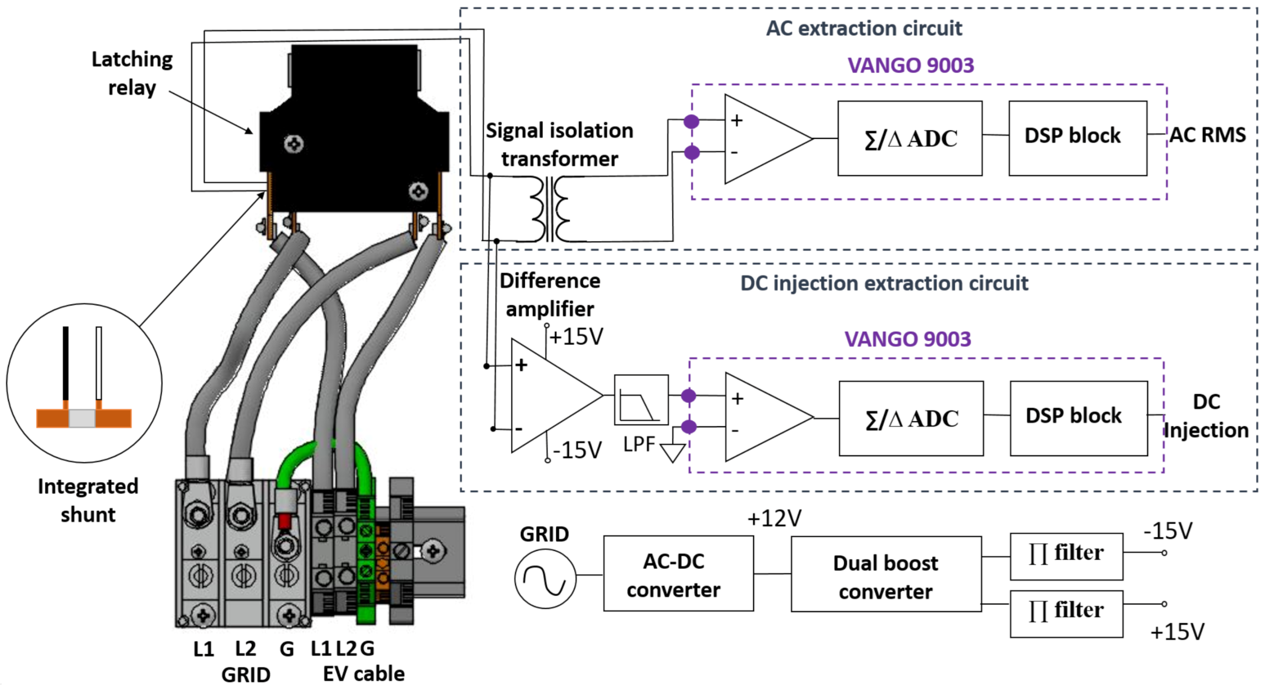
2.4. Prototype System Components

The single-phase system block diagram is presented in Figure 1. The current monitoring system is integrated into the EVSE hardware and consists of two major blocks: The current sensor hardware block and the micro controller signal processing block.
The sensor part is comprised of a shunt resistor integrated into a latching relay manufactured by KG Technology, Inc. The relay’s primary function is to de-energize the EV’s connection point when a vehicle is not actively charging or providing grid services. It is also used as the disconnection element in the EVSE’s integrated residual current device (RCD, not shown; also known in North America as a ground-fault circuit interrupter (GFCI)). It can also be used to disconnect the circuit in the event of a DC injection fault if the vehicle fails to comply with a request to stop charging/discharging.
There are two readout circuits for the single shunt sensor. In the first, the AC component is extracted via a signal isolation transformer (TTC-5036). This signal is passed directly to the one of the current inputs of a Vango 9003 metrology chip. This chip was designed primarily for use in smart energy meters.
In the second circuit the shunt signal is captured by a unity gain difference amplifier (AD8479). This amplifier is designed for high-voltage high-side sensing applications and, therefore, has a high input common mode voltage range and a high CMRR. The AD8479 requires a ±15 VDC power supply. In the proposed design this dual 15 VDC power supply is provided by a dual boost power converter (LT1945EMS) powered by the same AC-DC LPF-16-12 power supply that powers the rest of the EVSE.
While the DC injection detection circuit fails to block all of the AC common-mode signal, only the DC component is of interest. The Vango 9003 is capable of isolating AC and DC components of its analog inputs and, therefore, the parasitic common-mode voltage at the output of the amplifier does not impact the measurements. A first-order RC low pass filter with cut-off frequency of 1 Hz is included to decrease the AC signal component to prevent saturation of the 9003’s inputs if the particular amplifier has relatively low CMRR. The filter has a gain of −17.5 dB at 60 Hz frequency.
The signal is then processed by the Vango 9003 metrology chip. As mentioned above, the signal is split into AC and DC components by a decimation filter. As a result, the DC injection value can be detected and compared with the threshold for further actions like error message generation, requests for the vehicle to stop charging and/or opening the relay. Vango 9003 updates AC and DC measurements once per 20 ms and stabilizes in 80 ms.
All the elements are intended to be integrated into a printed circuit board (PCB) which also provides residual current detection and activates the safety relay. However, due to the timing and cost of the board fabrication constrains, the proof-of-concept prototype presented in this paper is designed on a separate small PCB board attached to the main one in several connection points.
This single-phase design can be extended to three phases by installing shunt sensors and signal extraction circuitry for each of the three phases. The Vango 9003 is capable of single and three-phase metering so there is no need to change the metering chip or to add more of them (Figure 1 shows utilization of two separate Vango 9003 microcontrollers for AC measurements and DC detection. We believe, however, that only one 9003 is required if DC detection is performed with the microcontroller’s auxiliary analog input with each phase being measured in turn. This solution will reduce the total cost of the system, which is critical for mass production of EVSE).
Specifications for the primary components of both the single and three-phase systems can be found in Table 2.

2.5. Design Challenges

2.5.1. Single Sensor for AC and DC Measurements

As was discussed in Section 2.2, the solution should employ a single sensor for both AC and DC measurements. The challenge in this approach is that the AC signal to be measured is two orders of magnitude larger than the expected DC signal (see Table 1), and, therefore, it is complicated to measure them effectively simultaneously.

2.5.2. High-Side Current Sensing

Due to the structure of the U.S. utility system and the EVSE, the only way to measure current with a shunt is high-side current sensing. This implies the presence of extremely high input common-mode voltage (Table 1) relative to the signal of interest, which makes it impossible to measure the AC current with the required precision with the typical high-side current sensing approach of an amplifier designed for this purpose. This is due to the presence of parasitic common-mode voltage at the output of the difference amplifier, which is significantly greater than the allowable error of AC current measurements. Based on the required AC current metering accuracy, the minimum AC current to be measured (Section 2.1) and the shunt resistance R = 280 μ Ω , the allowable voltage error is V e r r o r = 11.2 μ V ± 5% due to the shunt tolerance. The ten AD8479 unity gain difference amplifier’s output voltages were measured in the presence of 120 V common-mode voltage with no current flowing through the shunt. Test results show the parasitic voltage V p to be equal to 3.36 mV to 12 mV depending on the common-mode rejection ratio (CMRR) of the particular amplifier being tested (Table 2). These results are in line with the theoretical calculations below:
V p = A d ( V + V ) + 1 2 A c m ( V + + V )
where differential gain A d = 1 and input voltages V + = V = 120 V (current through the shunt I = 0 A).
Common-mode gain A c m can be obtained from the equation:
CMRR = 20 log 10 ( A d A c m ) dB
where CMRR is between 80 dB and 90 dB.
After calculating A c m , we can obtain the value of V p from (1), so that V p equals 3.8 mV to 12 mV. The measured minimum V p is lower than the calculated value. The difference could possibly be a result of the exceptional performance of one particular amplifier with CMRR above data sheet specification. Alternatively, it could be a result of a measurement error due to a difficulty in measuring very low signals accurately. Nevertheless, the difference does not affect the overall conclusion.

2.5.3. Power Dissipation and Energy Losses

Due to the shunt being installed into the conductive path, power dissipation and associated energy losses occur. This needs to be considered in the design.

2.6. Power and Energy Losses due to the Shunt

As discussed in Section 2.5.3, the shunt power dissipation must be considered as a potential problem due to excessive heat generation and energy/financial losses. In order to estimate the problem, the following calculations are considered:
P l o s s = I 2 R
where P l o s s is continuous power loss across the shunt, I = 60 A (typical operation), R = 280 μ Ω . We assume an EV performs a regulation service (20% duty cycle, duration t r e g = 22 h and duration of charging t c h = 1 h/day). Therefore energy loss E l o s s can be calculated:
E l o s s = P l o s s ( t c h + t r e g · 0.2 ) = 5.44 Wh / day
or ∼2 kWh/year.
Typical energy cost in the U.S. is approximately 12 cents/kWh [22]. Consequently the losses due to the shunt would be approximately ∼30 cents/year, this is inconsequential relative to the cost-savings over the incumbent solution (approximately $3 compared to $14 for the BCT-013-200 CT ) [23].
An additional concern related to the heat generation at high currents is the thermal effect on the accuracy of the shunt. However, considering the TCR of the shunt and the temperature rise in EVSE operating at 60 A (11 ° C) [24], the shunt can operate within the accuracy specification up to extreme high ambient temperatures (40–50 ° C).

3. Prototype Validation

We tested the prototype against three major requirements: The accuracy of bidirectional (EV charging/discharging) AC current measurement, the DC injection detection accuracy at the limit value of 400 mA and the potential effect of a large AC current on DC injection detection.

3.1. Accuracy of AC Current Measurements

Table 3 shows bidirectional AC current measurements from the Vango 9003 AC RMS channel using the prototype after the initial coarse hand calibration.
The reference AC current I r e f was provided by a Calmet C300B three-phase power calibrator and tester with a rated accuracy of 0.05%. Reference currents of 6 A, 10 A, 15 A, 20 A and 35 A were applied across the shunt in a presence of a common mode voltage V c m = 120 V (L-N single-phase). (The system was tested for linearity up to 80 A. These measurements are not shown in Table 3 and were not considered for the accuracy class estimation). The mean I m ¯ , standard deviation S( I m ¯ ), bias error and precision error were calculated for each value of a reference current [25]. Presumably assuming that bias error can be calibrated to near 0 value after careful fine calibration, the precision error is reported as accurate.
Note that only currents of maximum and minimum current test conditions were considered for the system’s accuracy class estimation (see Section 2.1). Other measurements are provided only for a reference. The measurements demonstrate that for charging and for discharging, the sensing system meets 0.5 accuracy class requirements for maximum current of 35 A, but the system does not meet the same class requirements for a minimum current of 6 A. Note that the sensor satisfies the requirements for 1.0 class accuracy for both test conditions.
In addition, we believe, that when the prototype circuit is integrated into the RCD board, it will improve errors resulting from the current prototype’s imperfect connections. Therefore, for further calibration and error reduction, the prototype circuit must be integrated into the main board (see Section 2.4).

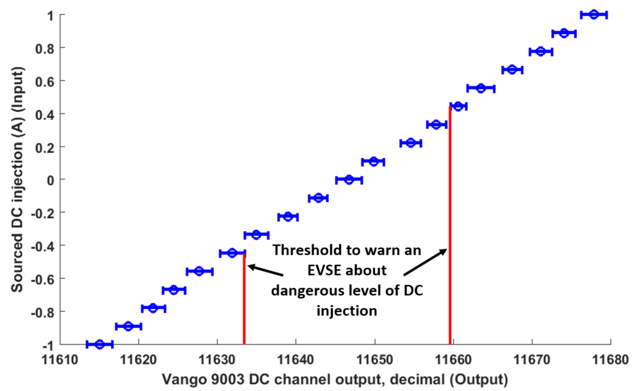
3.2. DC Injection Detection

3.2.1. Accuracy of DC Injection Detection

In order to determine DC injection detection accuracy for positive and for negative DC injection, a Keithley 2410 SourceMeter was used to supply high precision DC current (0.034% source accuracy) of −1 A to 1 A through the shunt sensor, and the Vango 9003 DC channel’s response was recorded.
These data are illustrated in Figure 2, which on the y-axis shows supplied DC current and on the x-axis shows linear function of DC current as measured by the current measuring system.
Each unit on the x-axis represents 33 mA. The small horizontal lines show the mean and a standard deviation of each 20 measurements at 100 mA intervals. The DC injection alarm threshold settings for positive (+400 mA) and negative (−400 mA) injections are depicted by red vertical lines. These thresholds are set at one standard deviation below 400 mA (or above −400 mA) to ensure that in 84% of the cases, DC injection will not exceed the limit of 400 mA. Specifically, σ = 33 mA (8.25% accuracy) for positive DC injection and σ = 66 mA (16.5% accuracy) for negative DC injection (the distribution around the positive threshhold is larger; it is a coincidence that sigma is twice the negative value). Setting the threshold at one standard deviation implies that the probability of a single non-compliant measurement failing to producing an alarm is 16%. Figure 2 shows the red threshholds already adjusted by one sigma closer to 0 mA.

3.2.2. Effect of Large AC Current on DC Injection Detection

An important factor potentially affecting the accuracy of DC injection detection is the presence of a large AC signal on the same line. In order to determine the effect of a large AC current on a DC injection reading, AC currents of 0.001 A and 80 A ( I r a t e d for 19.2 kW single-phase EVSE) were applied across the shunt. The test current was provided by a Calmet C300B three-phase power calibrator and tester with a rated accuracy of 0.05%. The output of the DC injection channel was recorded at two AC current values. Assuming that each population is normally distributed, a two-sample t-test of two populations without assuming equal variances (Welch’s t-test) was applied. The t-test result confirms the null hypothesis at the 5% significance level. Therefore, we conclude that DC injection can be detected in the presence of large AC currents without any significant distortion of the DC injection readings.

3.3. Prototype System Cost-Effectiveness

A comparison of the approximate cost of the system currently in use on single-phase EVSE units vs. that of the prototype is provided in Table 4. Cost estimate does not include parts with price below $0.5.
For the system in use (the left section) prices are listed for the major components: CT BCT-013-200 and Vango 9003 metrology chip. The Hall-effect sensor LA-150P with current range up to 150 A was added to the cost comparison to represent an additional cost for DC injection detection. (Note that LEM LA-150P was not tested for the ability to detect a small DC injection and is presented only for a cost comparison.) For our prototype shunt system (the right section) prices are listed for a shunt, Vango 9003, difference amplifier AD8479ARZ-RL, isolation transformer TTC-5036 and a boost converter LT1945EMS. The prototype system’s approximate total cost is less than half that of the CT and Hall-effect sensor.

3.4. Future Work

Going forward, the shunt sensor readout circuitry and the 15VDC dual boost converter PCBs should be integrated into the RCD board in the existing EVSE design.
Next, fine calibration of the sensing system for bidirectional AC current measurements must be performed to reduce bias error to near 0 value. The software would also be updated to respond appropriately to the DC injection information by issuing an error message and opening the safety relay.
Finally, these designs and concepts should be extended to three-phase EVSE.

4. Conclusions

A shunt-based AC and DC current sensing system for single-phase EVSE has been designed, prototyped and tested. This prototype has a potential to replace the CT based system currently in use in mass production EVSE. The new system is independent of the type of inverter used in any EV and thus is capable of interconnection with all types of EVs.
The prototype can simultaneously conduct high precision revenue metering and detect DC injection into the grid by EVs’ on-board equipment in case of a fault. This prototype is cost-effective relative to the system in use with added DC sensor.
Assuming fine calibration, the systems meets 1.0 accuracy class requirements for revenue metering.
The prototype can detect DC injection of 400 mA or more in AC signals up to 80 A. DC injection detection resolution is 33 mA. The accuracy of DC injection detection meets the accuracy requirements stated in Table 1. Due to extremely low shunt resistance, the prototype does not exhibit significant power losses at high currents, in contrast with other shunt systems.

Author Contributions

Conceptualization, O.M. and W.K.; Data curation, O.M.; Formal analysis, O.M.; Funding acquisition, W.K.; Investigation, O.M., G.E. and W.K.; Methodology, O.M. and G.E.; Project administration, W.K.; Validation, O.M. and G.E.; Visualization, O.M.; Writing—original draft, O.M.; Writing—review & editing, G.E. and W.K. All authors have read and agreed to the published version of the manuscript.

Funding

This research was funded by a grant from Nuvve Corp. to the University of Delaware. Research Agreement, 1 September 2019.

Institutional Review Board Statement

Not applicable.

Informed Consent Statement

Not applicable.

Data Availability Statement

The data that supports the central findings are presented within the article. Price data compiled from Digi-Key Electronics, Mouser Electronics, Vango Technology and KG Technologies for 1000+ quantity.

Acknowledgments

The authors thank Andrea Wait and Rodney T. McGee from University of Delaware for helpful discussions.The authors would also like to thank Fouad Kiamilev from University of Delaware for providing laboratory space and for valuable advice.

Conflicts of Interest

The authors declare no conflict of interest.

References

  1. Muscas, C.; Pau, M.; Pegoraro, P.A.; Sulis, S. Smart electric energy measurements in power distribution grids. IEEE Instrum. Meas. Mag. 2015, 18, 17–21. [Google Scholar] [CrossRef]
  2. IEEE 1547-2018, IEEE Standard for Interconnection and Interoperability of Distributed Energy Resources with Accociated Electric Power Systems Interfaces; IEEE Standards Association: Piscataway Township, NJ, USA, 2018.
  3. Gertmar, L.; Karlsson, P.; Samuelsson, O. On DC injection to AC grids from distributed generation. In Proceedings of the European Conference on Power Electronics and Applications, Dresden, Germany, 11–14 September 2005. [Google Scholar] [CrossRef]
  4. Zobaa, A.F.; Cecati, C. A Comprehensive Review on Distributed Power Generation. In Proceedings of the International Symposium on Power Electronics, Electrical Drives, Automation and Motion SPEEDAM, Taormina, Italy, 23–26 May 2006. [Google Scholar] [CrossRef]
  5. Kempton, W.; Tomić, J. Vehicle-to-grid power fundamentals: Calculating capacity and net revenue. J. Power Sources 2005, 144, 268–279. [Google Scholar] [CrossRef]
  6. Mironenko, O. Detection of DC Injection and Measuring AC Current with a Single System for Electric Vehicle Charging and Discharging. Ph.D. Thesis, University of Dealware, Newark, DE, USA, 2020; pp. 4–21. [Google Scholar]
  7. Rietveld, G.; Braun, J.P.; Martin, R.; Wright, P.; Heins, W.; Ell, N.; Clarkson, P.; Zisky, N. Measurement infrastructure to support the reliable operation of smart electrical grids. IEEE Trans. Instrum. Meas. 2015, 64, 1355–1363. [Google Scholar] [CrossRef]
  8. IEC 62053-11:2003, Electricity Metering Equipment (a.c.)—Particular Requirements—Part 11: Electromechanical Meters for Active Energy (Classes 0.5, 1 and 2); International Standard; International Electrotechnical Commission: Geneva, Switzerland, 2003.
  9. American National Standard for Electricity Meters 0.1, 0.2 and 0.5 Accuracy Classes, ANSI C.12-20; Approved American National Standard; American National Standards Institute: New York, NY, USA, 2017.
  10. Berba, F.; Atkinson, D.; Armstrong, M. A new approach of prevention of DC current component in transformerless grid-connected PV inverter application. In Proceedings of the IEEE 5th International Symposium on Power Electronics for Distributed Generation Systems (PEDG), Galway, Ireland, 24–27 June 2014; pp. 1–7. [Google Scholar] [CrossRef]
  11. Zhang, W.; Armstrong, M.; Elgendy, M. DC current determination in grid-connected transformerless inverter systems using a DC link sensing technique. In Proceedings of the 2017 IEEE Energy Conversion Congress and Exposition (ECCE), Cincinnati, OH, USA, 1–5 October 2017; pp. 5775–5782. [Google Scholar] [CrossRef]
  12. Abdelhakim, A.; Mattavelli, P.; Yang, D.; Blaabjerg, F. Coupled-inductor-based DC current measurement technique for transformerless grid-tied inverters. IEEE Trans. Power Electron. 2018, 33, 18–23. [Google Scholar] [CrossRef] [Green Version]
  13. EV Meter Accuracy Testing; Final Test Report for University of Delaware; Tesco Engineering: Jubail Industrial City, Saudi Arabia, 2019.
  14. Butcher, T.G. Specifications, Tolerances, and Other Technical Requirements for Weighing and Measuring Devices; Standard, National Institute of Standards and Technology Handbook 44; US Department of Commerce, National Institute of Standards and Technology: Gaithersburg, MD, USA, 2020.
  15. DR Metering Requirements; Technical Report; PJM: Norristown, PA, USA, 2018.
  16. Crescentini, M.; Marchesi, M.; Romani, A.; Tartagni, M.; Traverso, P.A. A broadband, on-chip sensor based on Hall effect for current measurements in smart power circuits. IEEE Trans. Instrum. Meas. 2018, 67, 1470–1485. [Google Scholar] [CrossRef]
  17. Masi, M.G.; Peretto, L.; Tinarelli, R. Design and performance analysis of a differential current sensor for power system applications. IEEE Trans. Instrum. Meas. 2012, 61, 3207–3215. [Google Scholar] [CrossRef]
  18. Xiao, C.; Zhao, L.; Asada, T.; Odendaal, W.; Van Wyk, J. An overview of integratable current sensor technologies. In Proceedings of the 38th IAS Annual Meeting on Conference Record of the Industry Applications Conference, Salt Lake City, UT, USA, 12–16 October 2003; Volume 2, pp. 1251–1258. [Google Scholar] [CrossRef]
  19. Laurent, A.F.; Iniewski, K. Novel Advances in Microsystems Technologies and Their Applications; CRC Press, Taylor & Francis Group: Boca Raton, FL, USA, 2016; pp. 266–287. [Google Scholar]
  20. Ripka, P. Electric current sensors: A review. Meas. Sci. Technol. 2010, 21, 112001. [Google Scholar] [CrossRef] [Green Version]
  21. Ziegler, S.; Woodward, R.C.; Iu, H.H.C.; Borle, L.J. Current sensing techniques: A review. IEEE Sens. J. 2009, 9, 354–376. [Google Scholar] [CrossRef]
  22. Monthly Electric Power Industry Report; Technical Report; U.S. Energy Information Administration: Washington, DC, USA, 2020.
  23. EKM Metering Inc. BCT-013-200 Current Transformer Spec Sheet; EKM Metering Inc.: Santa Cruz, CA, USA, 2020. [Google Scholar]
  24. EVSE High Current Tester Manual; Technical Report; University of Delaware: Newark, DE, USA, 2018.
  25. ISO 5725-1:1994(en) Accuracy (Trueness and Precision) of Measurement Methods and Results; International Standard; International Organization for Standardization: Geneva, Switzerland, 1994.
Figure 1. Current sensing single-phase system block diagram.
Energies 14 01193 g001
Figure 2. Setting the DC injection alarm threshold for positive (right line) and negative (left line) DC injection.
Energies 14 01193 g002
Table 1. Current metering system requirements for single-phase and for three-phase Electric Vehicle Supply Equipment (EVSE).
ParametersRequirements
Single-PhaseThree-Phase
(19.2 kW)(100 kW)
Voltage (L-N)120 V, 230 V230 V, 277 V, 347 V
DC injection limit0.5% of I r a t e d 0.5% of I r a t e d
DC injection detection accuracy20%20%
at the limit value
AC current metering accuracy classes0.5, 1.0, 2.00.5, 1.0, 2.0
I r a t e d 80 A120 A
Table 2. Main design parts specification.
Part NamePart NumberSpecifications
Relay with
shunt integrated
(single-phase)
K237X-S006P
-2AT-C946
Max current rating: 100 A
Shunt resistance: 280  μ Ω
Shunt tolerance: ±5%
Shunt Temperature Coefficient
of Resistance (TCR): 0–15 · 10 6 ( ° C) 1 (10–80 ° C)
Relay with
shunt integrated
(three-phase)
K316X-S006P
-3BT-C1047
Max current rating: 120 A
Shunt resistance: 280  μ Ω
Shunt tolerance: ±5%
Shunt Temperature Coefficient
of Resistance (TCR): 0–15 · 10 6 ( ° C) 1 (10–80 ° C)
Signal transformerTTC-5036Frequency range: 200 Hz–4 kHz
Voltage isolation: 1875  V r m s @1 s
Difference
amplifier
AD8479 V C M = 600 V
V s = ±15 V
CMRR = 80 dB–90 dB
Gain = 1
Signal processing
microcontroller
Vango9003Three-phase multi-functional
energy meter
Table 3. AC current measurements for charging and discharging.
Charging
I r e f (A) I m ¯ (A)S( I m ¯ ) (A)Bias error (%)Precision error (%)
66.150.0552.50.89
1010.140.0521.380.52
1515.090.0410.570.37
2020.090.0410.430.20
3535.20.0000.570.00
Discharging
I r e f (A) I m ¯ (A)S( I m ¯ ) (A)Bias (%)Precision error (%)
65.930.0521.10.87
109.960.0520.380.52
1515.950.0550.330.37
2019.990.0410.070.20
3535.060.0520.180.15
Table 4. Systems cost comparison for single-phase Electric Vehicle Supply Equipment (EVSE).
CT + Hall Effect SensorShunt Prototype System
Part NoQtyPricePart NoQtyPrice
BCT-013-200 CT1$14Shunt1$3
Vango 90031$3.15Vango 90031$3.15
LEM LA-150P1$19.04AD8479ARZ-RL1$4.25
TTC-50361$2.52
LT1945EMS1$2.60
Approximate total cost$36.19 $15.52
Publisher’s Note: MDPI stays neutral with regard to jurisdictional claims in published maps and institutional affiliations.

