
Novel Hybrid Reactive Distillation with Extraction and Distillation Processes for Furfural Production from an Actual Xylose Solution


Abstract
1. Introduction
2. Methods
2.1. Design and Simulation
2.2. Reactions and Kinetics
2.3. Economic Evaluation
2.4. Environmental Assessment
3. Results and Discussion
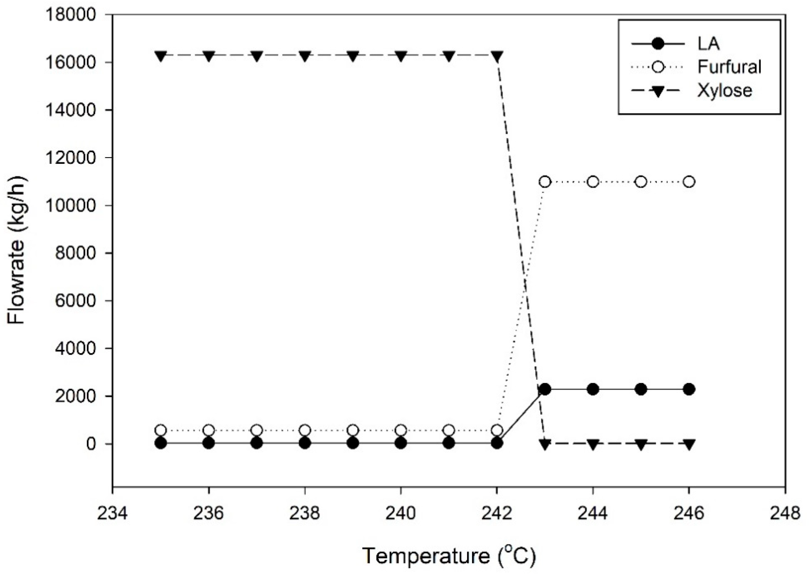
3.1. Furfural R-D Process
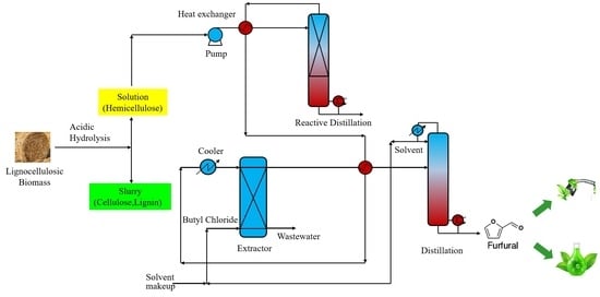
3.2. Improvement of the Conventional Furfural Production Process
3.2.1. Furfural R-ED Process
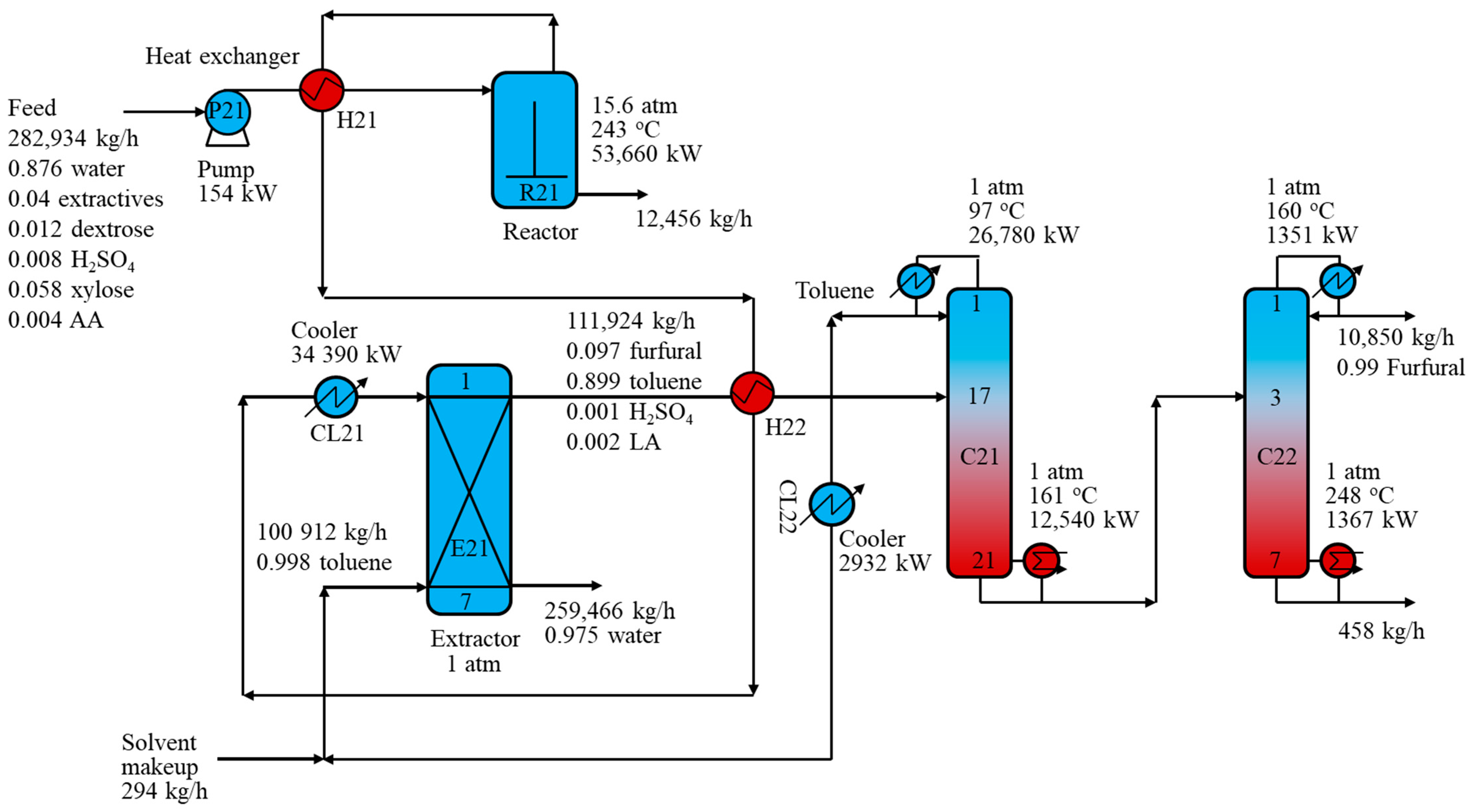
Toluene Solvent Process
BC Solvent Process
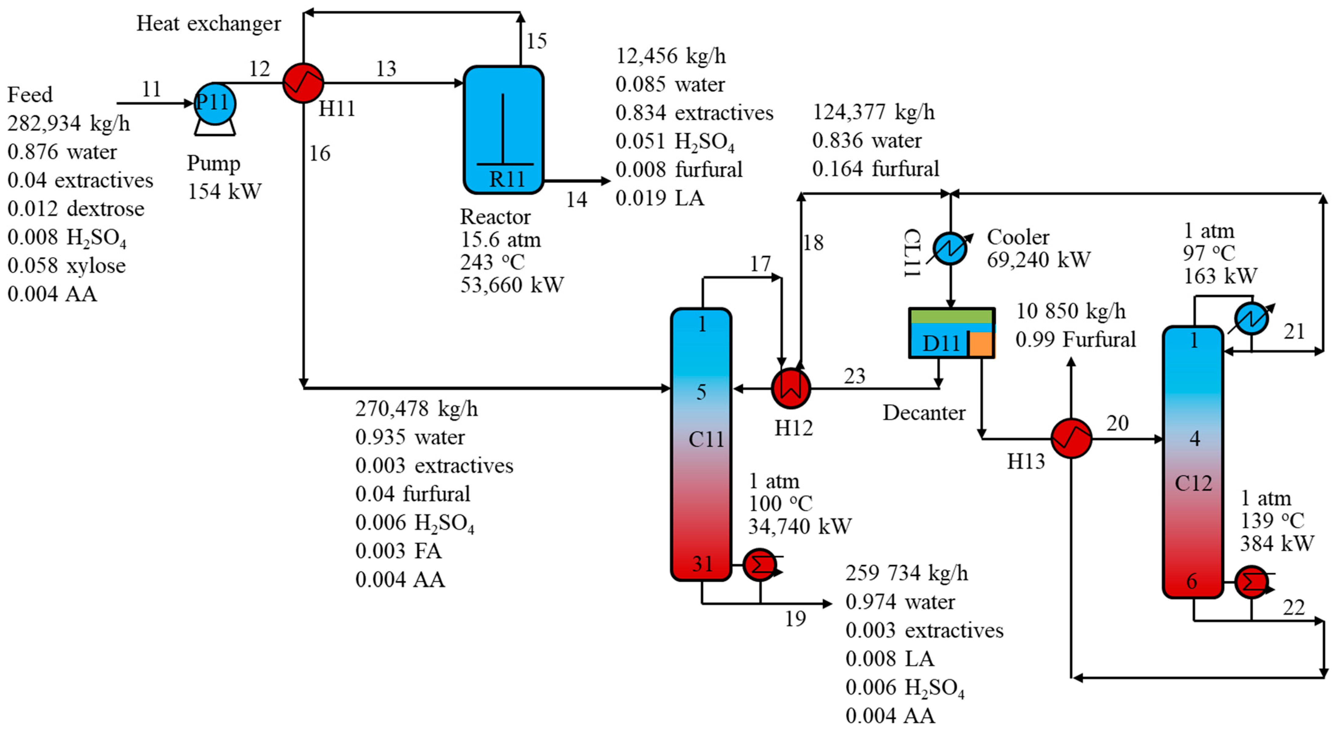
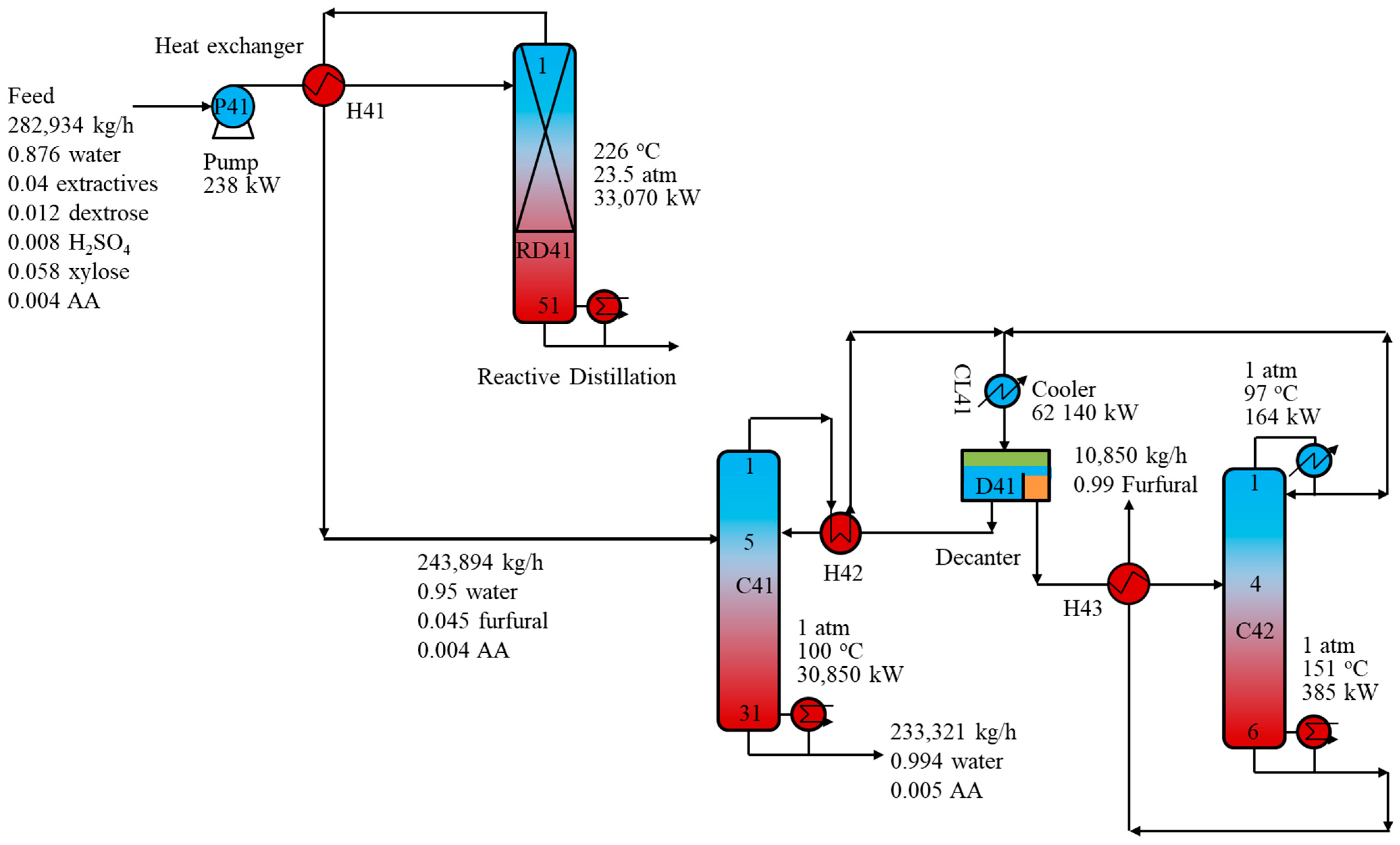
3.2.2. Furfural RD-D Process
3.2.3. Furfural RD-ED Process
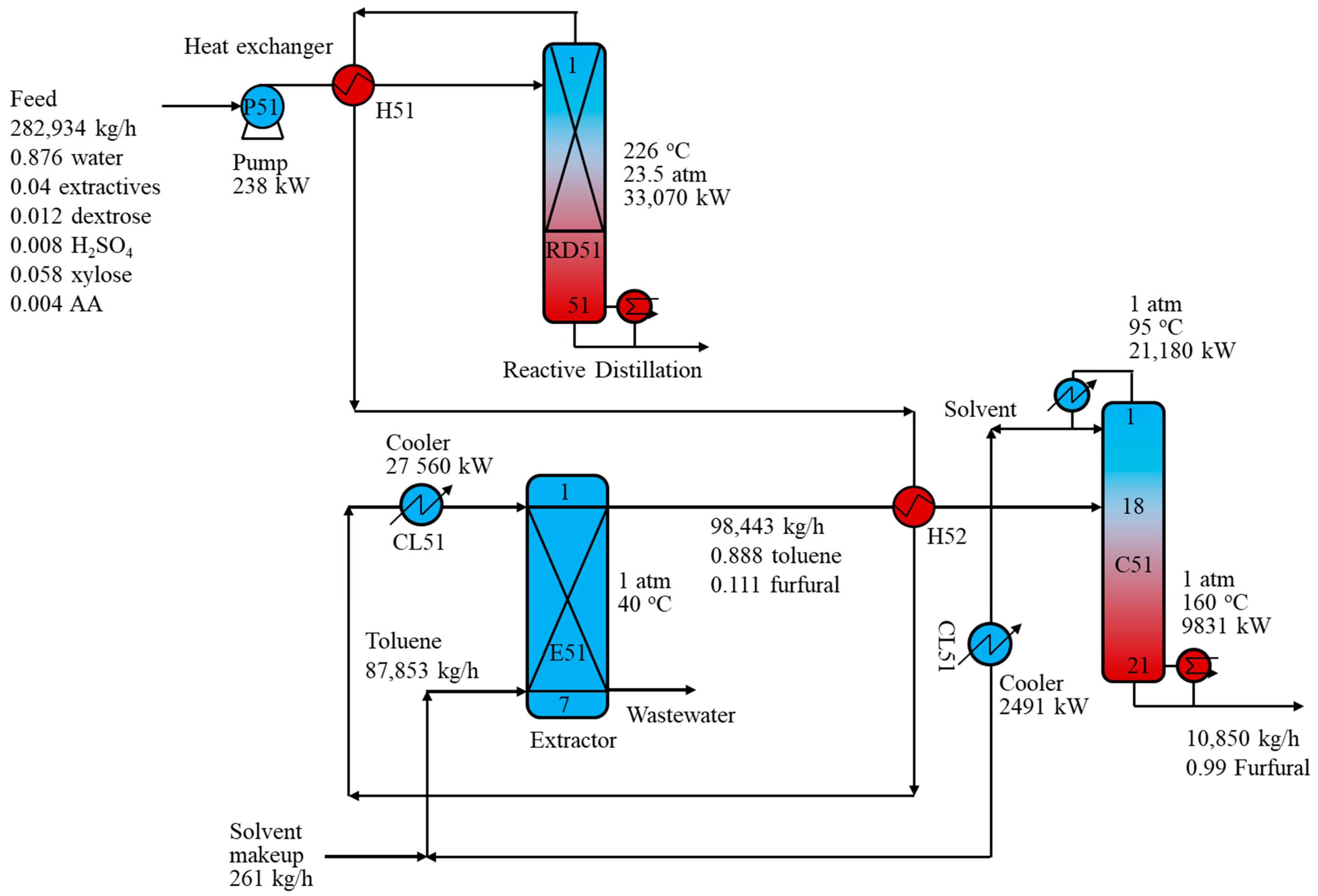
Toluene Solvent Process
BC Solvent Process
4. Conclusions
Author Contributions
Funding
Conflicts of Interest
Abbreviations
| AA | acetic acid |
| BC | butyl chloride |
| CO2 | carbon dioxide |
| CSTR | continuous stirred tank reactor |
| ED | extraction/distillation |
| FA | formic acid |
| HMF | hydroxylmethylfurfural |
| LA | levulinic acid |
| NHV | net heating value |
| NREL | National Renewable Energy Laboratory |
| NRTL | non-random two-liquid |
| HOC | Hayden–O’Connell |
| RD | reactive distillation |
| R-D | reaction-distillation |
| RD-ED | reactive distillation-extraction/distillation |
| R-ED | reaction-extraction/distillation |
| TIC | total investment cost |
| TOC | total annual operating costs |
| TCE | total annual CO2 emissions |
| TAC | total annual costs |
| UNIFAC: UNIQUAC | Functional-group Activity Coefficients |
| VLE | vapor-liquid equilibrium |
Appendix A

| Utility | Price ($/GJ) |
|---|---|
| Cooling water | 0.35 |
| Low-pressure steam | 13.28 |
| Medium-pressure steam | 14.19 |
| High-pressure steam | 17.70 |
References
- Werpy, T.; Petersen, G. Top. Value Added Chemicals from Biomass Volume I—Results of Screening for Potential Candidates from Sugars and Synthesis Gas; National Renewable Energy Laboratory (NREL): Golden, CO, USA, 2004. [Google Scholar]
- Hoydonckx, H.E.; Van Rhijn, W.M.; Van Rhijn, W.; De Vos, D.E.; Jacobs, P.A. Furfural and Derivatives. In Ullmann’s Encyclopedia of Industrial Chemistry; Wiley-VCH Verlag GmbH & Co. KGaA: Weinheim, Germany, 2000; ISBN 9783527306732. [Google Scholar]
- Nhien, L.C.; Long, N.V.D.; Kim, S.; Lee, M. Design and optimization of intensified biorefinery process for furfural production through a systematic procedure. Biochem. Eng. J. 2016, 116, 166–175. [Google Scholar] [CrossRef]
- Zeitsch, K.J. The Chemistry and Technology of Furfural and Its Many By-Products; Elsevier Science: Amsterdam, The Netherlands, 2000. [Google Scholar]
- De Jong, W.; Marcotullio, G. Overview of Biorefineries based on Co-Production of Furfural, Existing Concepts and Novel Developments. Int. J. Chem. React. Eng. 2010, 8. [Google Scholar] [CrossRef]
- Metkar, P.S.; Till, E.J.; Corbin, D.R.; Pereira, C.J.; Hutchenson, K.W.; Sengupta, S.K. Reactive distillation process for the production of furfural using solid acid catalysts. Green Chem. 2015, 17, 1453–1466. [Google Scholar] [CrossRef]
- Malone, M.F.; Doherty, M.F. Reactive Distillation. Ind. Eng. Chem. Res. 2000, 39, 3953–3957. [Google Scholar] [CrossRef]
- Mandalika, A.; Runge, T. Enabling integrated biorefineries through high-yield conversion of fractionated pentosans into furfural. Green Chem. 2012, 14, 3175–3184. [Google Scholar] [CrossRef]
- Marcotullio, G. The Chemistry and Technology of Furfural Production in Modern Lignocellulose-Feedstock Biorefineries. Ph.D. Thesis, Delft University of Technology, Delft, The Netherlands, 2011. [Google Scholar]
- de Jong, W.; Marcotullio, G. Process for the Production of Furfural from Pentoses. U.S. Patent 12/944,403, 3 May 2012. [Google Scholar]
- Nhien, L.C.; Long, N.V.D.; Kim, S.; Lee, M. Techno-economic assessment of hybrid extraction and distillation processes for furfural production from lignocellulosic biomass. Biotechnol. Biofuels 2017, 10. [Google Scholar] [CrossRef] [PubMed]
- Humbird, D.; Davis, R.; Tao, L.; Kinchin, C.; Hsu, D.; Aden, A.; Schoen, P.; Lukas, J.; Olthof, B.; Worley, M.; et al. Process. Design and Economics for Biochemical Conversion of Lignocellulosic Biomass to Ethanol: Dilute-Acid Pretreatment and Enzymatic Hydrolysis of Corn Stover; National Renewable Energy Laboratory: Golden, CO, USA, 2011. [Google Scholar]
- Aspentech. Aspen Physical Property System—Physical Property Methods V7.3; Aspen Technology, Inc.: Bedford, MA, USA, 2011. [Google Scholar]
- Carrasco, F.; Roy, C. Kinetic study of dilute-acid prehydrolysis of xylan-containing biomass. Wood Sci. Technol. 1992, 26, 189–208. [Google Scholar] [CrossRef]
- Bhandari, N.; Macdonald, D.G.; Bakhshi, N.N. Kinetic studies of corn stover saccharification using sulphuric acid. Biotechnol. Bioeng. 1984. [Google Scholar] [CrossRef] [PubMed]
- CHANG, C.; MA, X.; CEN, P. Kinetics of Levulinic Acid Formation from Glucose Decomposition at High Temperature. Chinese J. Chem. Eng. 2006, 14, 708–712. [Google Scholar] [CrossRef]
- Smith, R. Chemical Process. Design and Integration; Wiley: West Sussex, UK, 2016. [Google Scholar]
- Biegler, L.T.; Grossmann, I.E.; Westerberg, A.W. Systematic Methods of Chemical Process. Design; Prentice Hall Inc.: Uppler Saddle River, NJ, USA, 1997. [Google Scholar]
- Turton, R.; Bailie, R.C.; Whiting, W.B.; Shaeiwitz, J.A.; Bhattacharyya, D. Analysis, Synthesis, and Design of Chemical Processes, 4th ed.; Prentice Hall: Upper Saddle River, NJ, USA, 2016. [Google Scholar]
- Gadalla, M.A.; Olujic, Z.; Jansens, P.J.; Jobson, M.; Smith, R. Reducing CO2 emissions and energy consumption of heat-integrated distillation systems. Environ. Sci. Technol. 2005, 39, 6860–6870. [Google Scholar] [CrossRef] [PubMed]
- Grand View Research. Furfural Market Analysis by Application (Furfuryl Alcohol, Solvent) and Segment Forecasts to 2020; Grand View Research: San Francisco, CA, USA, 2015. [Google Scholar]
- Strømsnes, L.M.; Moe, S. Process Modeling of a Biorefinery for Integrated Production of Ethanol and Furfural in HYSYS. Ph.D. Thesis, Norwegian University of Science and Technology, Tronholm, Norway, 2016. [Google Scholar]


| Stream | 11 | 12 | 13 | 14 | 15 | 16 | 17 | 18 | 19 | 20 | 21 | 22 | 23 |
| Temperature (°C) | 55 | 55 | 203 | 243 | 243 | 200 | 99 | 99 | 100 | 91 | 97 | 139 | 89 |
| Pressure (atm) | 1 | 15.6 | 15.6 | 15.6 | 15.6 | 15.6 | 1 | 1 | 1 | 1 | 1 | 1 | 1 |
| Mass flowrate (kg/h) | 282,934 | 282,934 | 282,934 | 12,457 | 270,478 | 270,478 | 124,888 | 124,888 | 259,223 | 11,191 | 361 | 10,842 | 113,633 |
| Mass fraction | - | - | - | - | - | - | - | - | - | - | - | - | - |
| Water | 0.876 | 0.876 | 0.876 | 0.085 | 0.935 | 0.935 | 0.837 | 0.837 | 0.974 | 0.029 | 0.593 | 0.010 | 0.915 |
| Extractives | 0.040 | 0.040 | 0.040 | 0.834 | 0.003 | 0.003 | 0.000 | 0.000 | 0.003 | 0.000 | 0.000 | 0.000 | 0.000 |
| Dextrose | 0.012 | 0.012 | 0.012 | 0.000 | 0.000 | 0.000 | 0.000 | 0.000 | 0.000 | 0.000 | 0.000 | 0.000 | 0.000 |
| H2SO4 | 0.008 | 0.008 | 0.008 | 0.051 | 0.006 | 0.006 | 0.000 | 0.000 | 0.006 | 0.000 | 0.000 | 0.000 | 0.000 |
| Xylose | 0.058 | 0.058 | 0.058 | 0.001 | 0.000 | 0.000 | 0.000 | 0.000 | 0.000 | 0.000 | 0.000 | 0.000 | 0.000 |
| Levulinic acid | 0.000 | 0.000 | 0.000 | 0.019 | 0.008 | 0.008 | 0.000 | 0.000 | 0.008 | 0.000 | 0.000 | 0.000 | 0.000 |
| Furfural | 0.002 | 0.002 | 0.002 | 0.008 | 0.040 | 0.040 | 0.163 | 0.163 | 0.000 | 0.971 | 0.403 | 0.990 | 0.084 |
| Formic acid | 0.000 | 0.000 | 0.000 | 0.001 | 0.003 | 0.003 | 0.000 | 0.000 | 0.003 | 0.000 | 0.000 | 0.000 | 0.000 |
| Acetic acid | 0.004 | 0.004 | 0.004 | 0.001 | 0.004 | 0.004 | 0.000 | 0.000 | 0.005 | 0.000 | 0.000 | 0.000 | 0.000 |
| Ethanol | 0.000 | 0.000 | 0.000 | 0.000 | 0.000 | 0.000 | 0.000 | 0.000 | 0.000 | 0.000 | 0.004 | 0.000 | 0.000 |
| C11 | C12 | C21 | C22 | C31 | RD41 | C41 | C42 | C51 | C61 | |
|---|---|---|---|---|---|---|---|---|---|---|
| Tray type | Valve | Valve | Valve | Valve | Valve | Valve | Valve | Valve | Valve | Valve |
| Column diameter (m) | 4.1 | 0.41 | 4.84 | 0.91 | 2.46 | 2.04 | 4.61 | 0.41 | 4.23 | 2.16 |
| Number of trays | 31 | 6 | 21 | 7 | 21 | 51 | 31 | 6 | 21 | 13 |
| Tray spacing (m) | 0.61 | 0.61 | 0.61 | 0.61 | 0.61 | 0.61 | 0.61 | 0.61 | 0.61 | 0.61 |
| Stream | Reactor Top Vapor | RD Top Vapor |
|---|---|---|
| Mass flowrate (kg/h) | 270,478 | 243,894 |
| Water (kg/h) | 252,903 | 231,702 |
| Extractive (kg/h) | 885 | 5 |
| Dextrose (kg/h) | 0 | 1 |
| H2SO4 (kg/h) | 1666 | 47 |
| Xylose (kg/h) | 1 | 5 |
| Levulinic acid (kg/h) | 2054 | 39 |
| Furfural (kg/h) | 10,883 | 10,889 |
| Formic acid (kg/h) | 898 | 96 |
| Acetic acid (kg/h) | 1181 | 1102 |
| Ethanol (kg/h) | 7 | 7 |
| Process | R-D | R-ED (Toluene) | R-ED (BC) | RD-D | RD-ED (Toluene) | RD-ED (BC) |
|---|---|---|---|---|---|---|
| Reboiler duties (kW) | 88,784 | 67,567 | 55,108 | 64,305 | 42,901 | 33,706 |
| Reboiler duty savings | - | 23.9% | 37.9% | 27.6% | 51.7% | 62.0% |
| Condenser duties (kW) | 69,403 | 65,453 | 52,979 | 62,304 | 51,231 | 42,126 |
| Condenser duty savings | - | 5.7% | 23.7% | 10.2% | 26.2% | 39.3% |
| Total investment costs ($ in thousands) | 14,862 | 13,017 | 9653 | 12,942 | 9485 | 7164 |
| Investment cost savings | - | 12.4% | 35.0% | 12.9% | 36.2% | 51.8% |
| Total annual operating costs ($ in thousands) | 43,639 | 35,594 | 29,959 | 30,968 | 22,508 | 18,457 |
| Annual operating cost savings | - | 18.4% | 31.3% | 29.0% | 48.4% | 57.7% |
| Total annual costs ($ in thousands) | 45,854 | 37,534 | 31,398 | 32,896 | 23,921 | 19,525 |
| Annual cost savings | - | 18.1% | 31.5% | 28.3% | 47.8% | 57.4% |
| Total annual CO2 emissions (tons per year) | 208,561 | 167,364 | 140,029 | 148,092 | 105,516 | 85,747 |
| Annual CO2 reduction | - | 19.8% | 32.9% | 29.0% | 49.4% | 58.9% |
Publisher’s Note: MDPI stays neutral with regard to jurisdictional claims in published maps and institutional affiliations. |
© 2021 by the authors. Licensee MDPI, Basel, Switzerland. This article is an open access article distributed under the terms and conditions of the Creative Commons Attribution (CC BY) license (http://creativecommons.org/licenses/by/4.0/).
Share and Cite
Nhien, L.C.; Long, N.V.D.; Lee, M. Novel Hybrid Reactive Distillation with Extraction and Distillation Processes for Furfural Production from an Actual Xylose Solution. Energies 2021, 14, 1152. https://doi.org/10.3390/en14041152
Nhien LC, Long NVD, Lee M. Novel Hybrid Reactive Distillation with Extraction and Distillation Processes for Furfural Production from an Actual Xylose Solution. Energies. 2021; 14(4):1152. https://doi.org/10.3390/en14041152
Chicago/Turabian StyleNhien, Le Cao, Nguyen Van Duc Long, and Moonyong Lee. 2021. "Novel Hybrid Reactive Distillation with Extraction and Distillation Processes for Furfural Production from an Actual Xylose Solution" Energies 14, no. 4: 1152. https://doi.org/10.3390/en14041152
APA StyleNhien, L. C., Long, N. V. D., & Lee, M. (2021). Novel Hybrid Reactive Distillation with Extraction and Distillation Processes for Furfural Production from an Actual Xylose Solution. Energies, 14(4), 1152. https://doi.org/10.3390/en14041152