1. Introduction
A good modeling practice requires that the numerical models of structural mechanics, specifically the idealizations of member connections and stiffness of structures, are validated by in situ or laboratory tests. Lee and McClure [
1] validated a three-dimensional truss model of a lattice tower based on the results of full-scaled bending and flexure-torsion tests. This model accounts for the torsional deformation of the tower truss and the stiffness of the bonds, which are usually omitted from the calculation procedure. Szafran et al. [
2] used a numerical model, constructed and validated with in situ tests, to investigate the response of a tower structure to randomly generated wind loads, accounting for the dynamic response of the structure. Reliability analysis using first-order and second-order reliability methods was performed. Blum and Rasmussen presented their research on the stiffness of connections in portal frames [
3], in which they investigated frames consisting of double-channel sections joined by bolted connections and angles. They found a significant influence of knee brace-to-column connection stiffness on the distribution of cross-section forces.
The results of laboratory and numerical investigations of dynamic response of beams to the impact of falling mass were carried out by D’Antimo et al. [
4]. They demonstrated the suitability of calculations for the purpose of estimating the dynamic characteristics of a steel structure. Static and dynamic field tests of the response of corrugated steel plate culvert structures were presented by Beden [
5]. Following field tests, he determined the dynamic amplification factor (DAF) on the basis of displacement and deformation measurements, showing that its value is determined by the culvert width and vehicle speed. In a numerical study of the DAF for steel box girders by Rahbar-Ranji [
6], numerical simulations for different velocities and accelerations showed the dynamic factor for these structures and that the DAF takes relatively high values in the range of low lifting velocities, which is not accounted for by local regulations. Parida and Talukdar [
7] carried out research on the DAF in steel truss girder bridges, analyzing the influence of span length, traffic speed and volume, and technical condition of the bridge on the dynamic factor value. They found that the dynamic factor depends on movement conditions and that it reaches different values for different elements of a girder.
Khan and Krige [
8] investigated the structural integrity of shaft steelwork in the context of South African shafts. They accounted for the impact of structural weakness resulting from corrosion in steelwork elements. Experimental research on the load-carrying capacity of shaft guides was conducted by Fiołek and Jakubowski [
9] and Fiołek et al. [
10]. They showed that high corrosion loss reduces the resistance to local buckling of hot-rolled profiles. They demonstrated the suitability of the finite element (FE) computational approach and Eurocode 3 procedures for assessing the load-carrying capacity of the guides, even in a state of high corrosion loss.
Lateral movements of mine conveyances induce forces acting on steelwork structures. These movements are caused by misaligned guidelines and non-uniform mass distribution in the conveyance, resulting in forces at the contact between the conveyance guide rollers or shoes and the guide. Heyns and Heyns [
11] presented research on guide loads based on dynamic conveyance–steelwork models. They proposed a 3D conveyance model consisting of mass and the moment of inertia with six degrees of freedom. The interaction between the conveyance and the guide was modelled with elastic constraints. The guide was represented by beam finite elements, while the buntons were represented by truss elements with one degree of freedom. A dynamic model of a conveyance that incorporated the mass and moment of inertia was presented by Xing-Ming et al. [
12]. The guide roller was represented by a parallel-connected elastic element and a viscous damper element. The dynamic model was used to assess conveyance vibrations caused by the three most common types of guideline damage. The data obtained from the model and the results of vibration measurements showed strong agreement. A method of detecting failures of guide rail according to multi-time scale and dynamic time warping was present by Wu et al. [
13]. They analyzed the vibration signal under three types of guide failure and showed high accuracy of the method. It has been observed that guide misalignments affect guide loads. Wolny and Matachowski [
14] made an effort to assess guide load forces based on misalignment measurements. They presented a 3D shell and beam FE model of skip to estimate forces and stresses in the loaded conveyance components. They measured strains to validate the numerical simulation and their results of the simulation and measurements were consistent in terms of guide loads. They noticed major discrepancies in skip deformations and stresses and explained them by differences between the model and the actual skip construction. Despite the apparent theoretical description of the conveyance–steelwork system behavior, the diversity and complexity of causal effects and interactions make the assessment of forces with theoretical models inaccurate [
15].
The current routines and regulations for shaft steelwork design in South Africa, Australia, New Zealand and Poland [
16,
17,
18] consider the connections between the guide and the bunton to be pinned. This is a conservative approach that leads to oversimplified calculations and increased design loads and displacements. Such safe approximation may be seen as justified by the expected degradation of the connections as a result of increased corrosion in the shaft. However, it is not supported by any research known to the authors. The existing literature lacks research on the stiffness of connections of shaft guides, either new or corroded under shaft conditions. This deficiency of research precludes an accurate assessment of the actual connection rigidity and distribution of cross-sectional forces along the guide axis. It also prevents the correct calculation of the steelwork response to dynamic loads. The aim of this study was to fill these gaps and examine the stiffness of the shaft steelwork, the actual support conditions of guides, and the dynamic characteristics of the steelwork structure. As part of the research program, load tests of the steelwork were performed in shafts, numerical FE models were built and validated, and a series of linear and non-linear static and dynamic simulations were performed.
2. Shaft Steelwork Stiffness
2.1. In Situ Load Test of the Structure
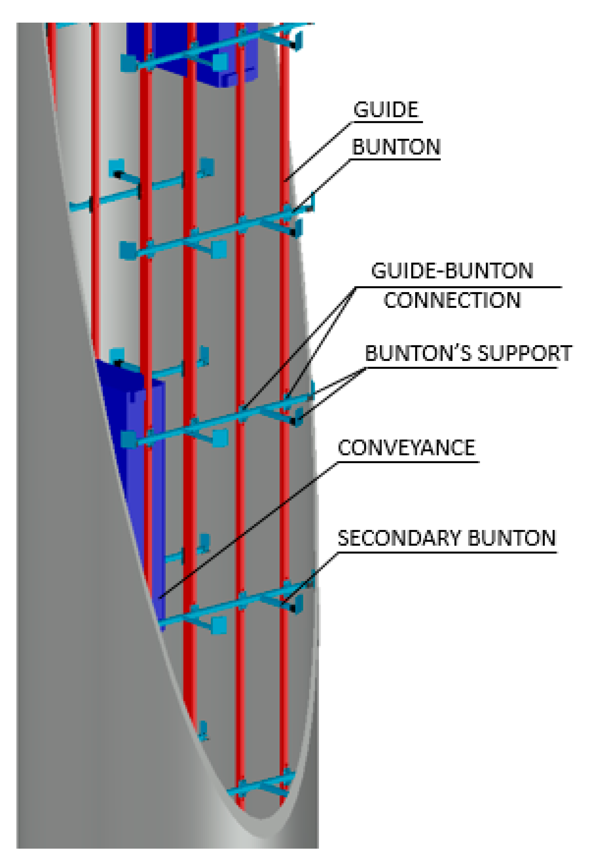
Shaft steelwork directs the linear motion of mine conveyances in vertical shafts. Cages and skips 20–80 Mg in total mass move along the guides at 20–60 km/h. The main shaft steelwork components in Silesian hard coal mines include main and secondary buntons mounted horizontally and guides mounted to buntons vertically.
Figure 1 shows a simplified steelwork visualization.
Bolted connections are used to connect the members in the structure. Buntons are fixed by short cast iron or steel brackets anchored in the shaft’s concrete lining. Horizontal buntons are configured 4.5 m apart along the shaft axis. Each guide segment is 9 m long and is fixed to three buntons. This system may, therefore, be considered a 3D frame made of hot-rolled sections jointed with bolted connections and loaded with forces from the impact of conveyance guides.
As part of the field tests, a load test was applied to one of the Upper Silesian hard coal mine shafts. The guides in the examined shaft were made of standard European channels, while the buntons were of equal angles. The cross-section of the guides and buntons is given in
Figure 2. The guide was connected to the bunton with bolts.
Figure 3 shows two types of these connections.
The shaft we examined was a two-compartment shaft used for mine output and staff transport with four four-deck cages.
Figure 4 presents a photo taken by the authors on the cage top transom showing the connection between the guide and the bunton as well as the guide roller, through which the carried load interacts with the guide.
The stiffness of the connections was tested directly in a shaft 850 m deep. Two series of measurements for each diagram were carried out in arbitrary locations at depths of 150 m (series 1) and 450 m (series 2). The thickness of the walls of the steelwork members was measured with a PosiTector ultrasonic thickness gauge manufactured by DeFelsko (Ogdensburg, NY, United States). The thickness was close to the nominal value and did not indicate any considerable corrosion.
The procedure we followed for the in situ load tests is shown in
Figure 5. Briefly, the guide was statically loaded with a chain hoist. The force applied to the guide was measured with a dynamometer; the displacement near the point of force application and rotation angles near the connection between the bunton and the guide were measured with a displacement gauge and inclinometers. The guide displacement measurements were taken with dial sensors manufactured by Mitutoyo (Kawasaki, Japan) with an accuracy of 10
−2 mm. The bunton displacement measurement was taken with a laser distance sensor manufactured by Baumer (Friedberg, Germany) with an accuracy of 10
−3 mm. The rotation angles were measured with Tuff Tilt inclinometers manufactured by Jewell Instruments (Manchester, United Kingdom) with an accuracy of 6·10
−4 degrees.
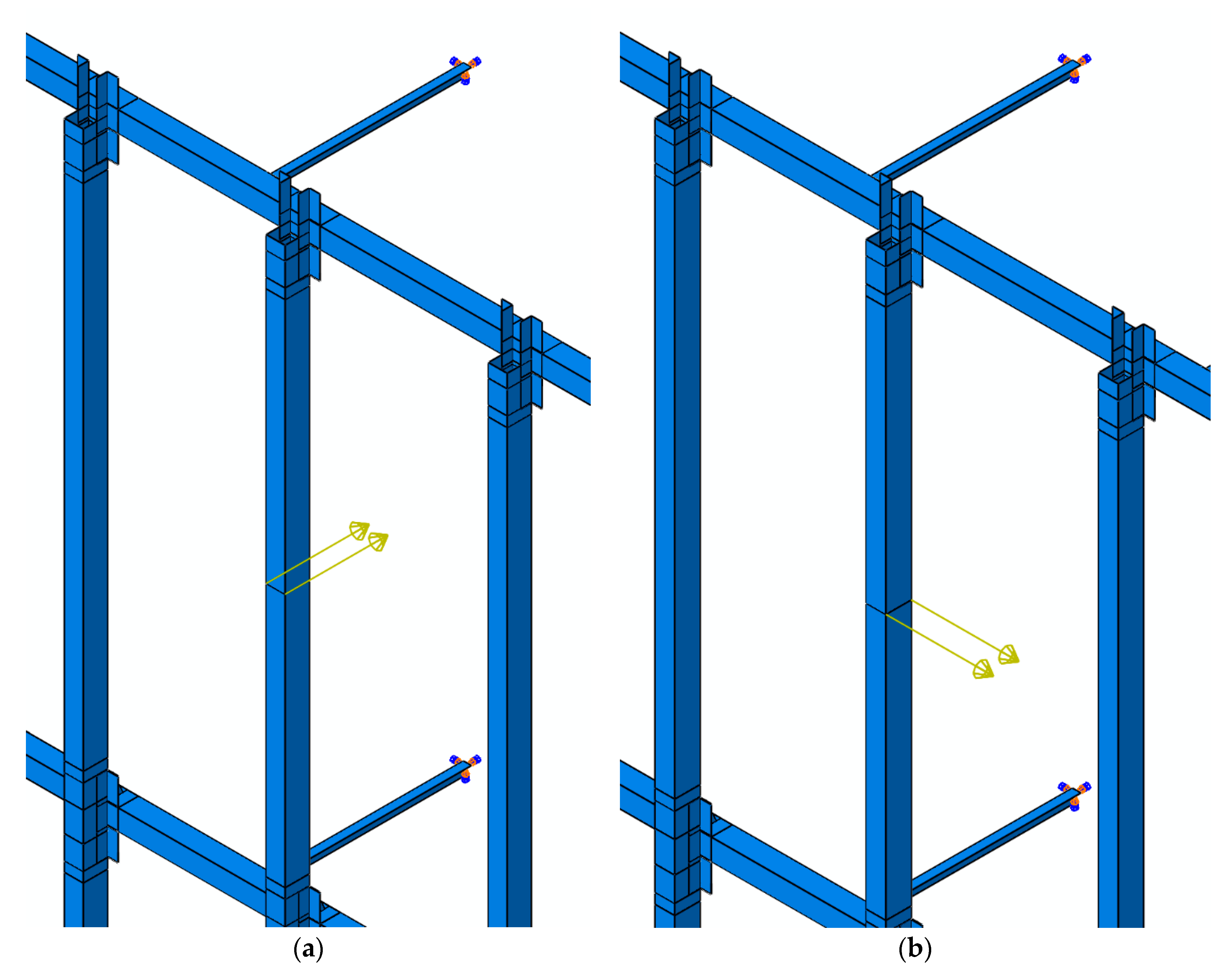
The displacement measurements were taken for three force application points in three schemes (
Figure 5) to provide comprehensive data on the guide’s deformability. For scheme A, the force was applied to the mid-point between the buntons, and we measured the displacement of the guide in the loaded section. For scheme B, the force was applied 1.5 m from the bunton axis towards the guide–bunton connection at the mid-point of the guide. The measured values included guide rotation angles on both connection sides at a distance of 60 cm from the bunton axis. For scheme C, the force was applied 1.5 m from the bunton axis towards the guide–bunton connection at the end of the guide. The measured values included the rotation angle of the guide section at a distance of 60 cm from the bunton axis and the corresponding vertical displacement. For schemes B and C, the bunton axis displacement in the direction of the force application was also measured.
2.2. Finite Element Model of the Steelwork Structure
A FE model of the steelwork structure was developed in Abaqus 6.12 based on the design documentation and site visits. In Polish mines, steelwork geometry is regularly monitored by staff and external inspections [
18,
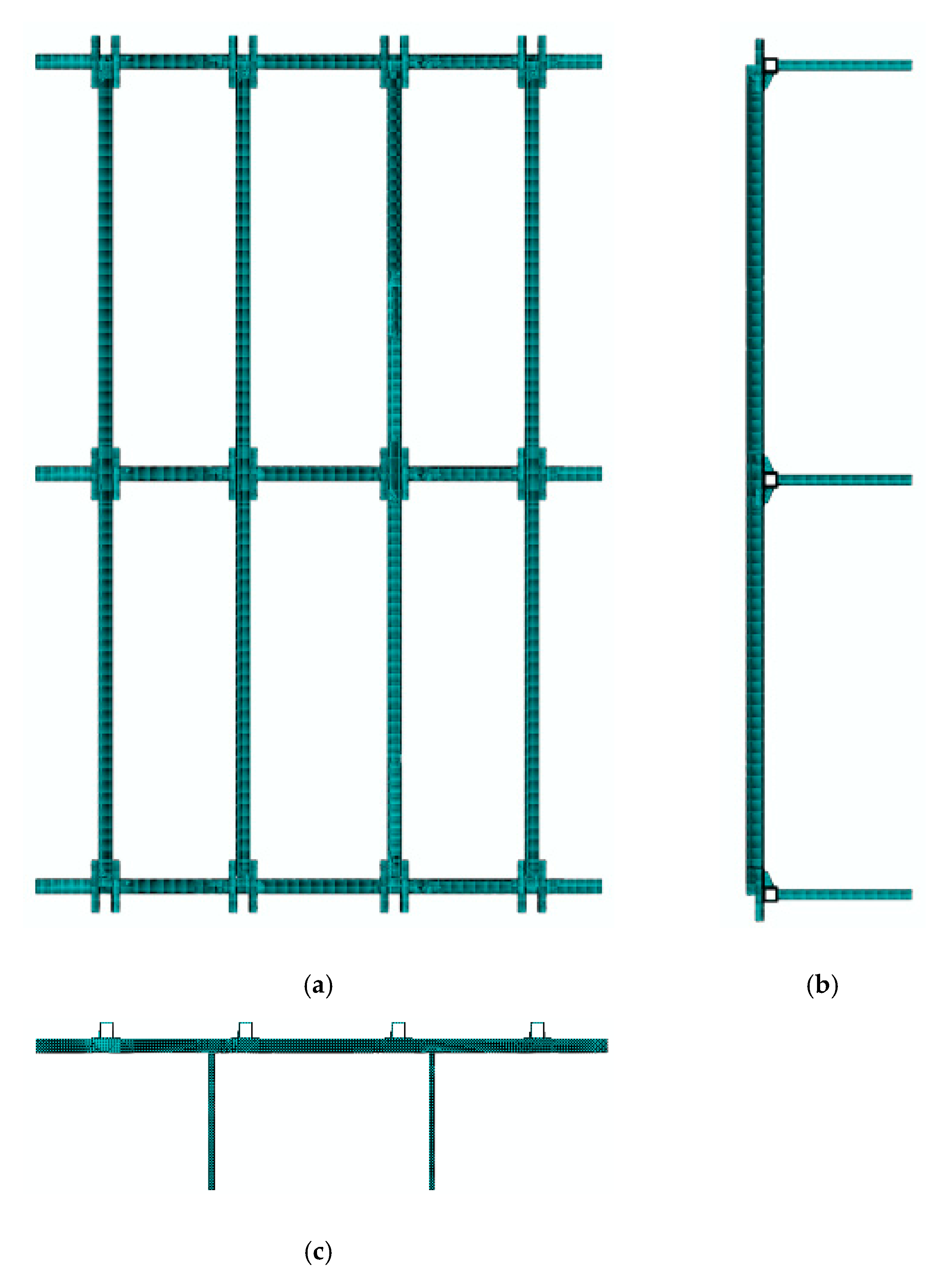
19]. The geometry of a repeatable steelwork segment was considered, including three main buntons, to which four 9 m guides and secondary buntons were mounted. The sections of the steelwork were represented by four-node shell elements with reduced integration (S4R) [
20]. Elastic constants for steel were adopted following EC3 [
21], specifically Young’s modulus E = 210 GP and Poisson’s ratio ν = 0.3. Due to the potentially large displacements and deformations, a geometric non-linear analysis was performed. Although the components were not expected to yield, this possibility could not be ruled out, so material nonlinearity was introduced. Steel was reproduced using an elastic-perfectly plastic (bilinear) model based on the HMH yield criterion. A yield strength of 355 MPa was adopted according to EC3 for the steel grade from which the steelwork was constructed. Boundary conditions reflected the conditions of the in situ load tests, as described in
Section 2.1.
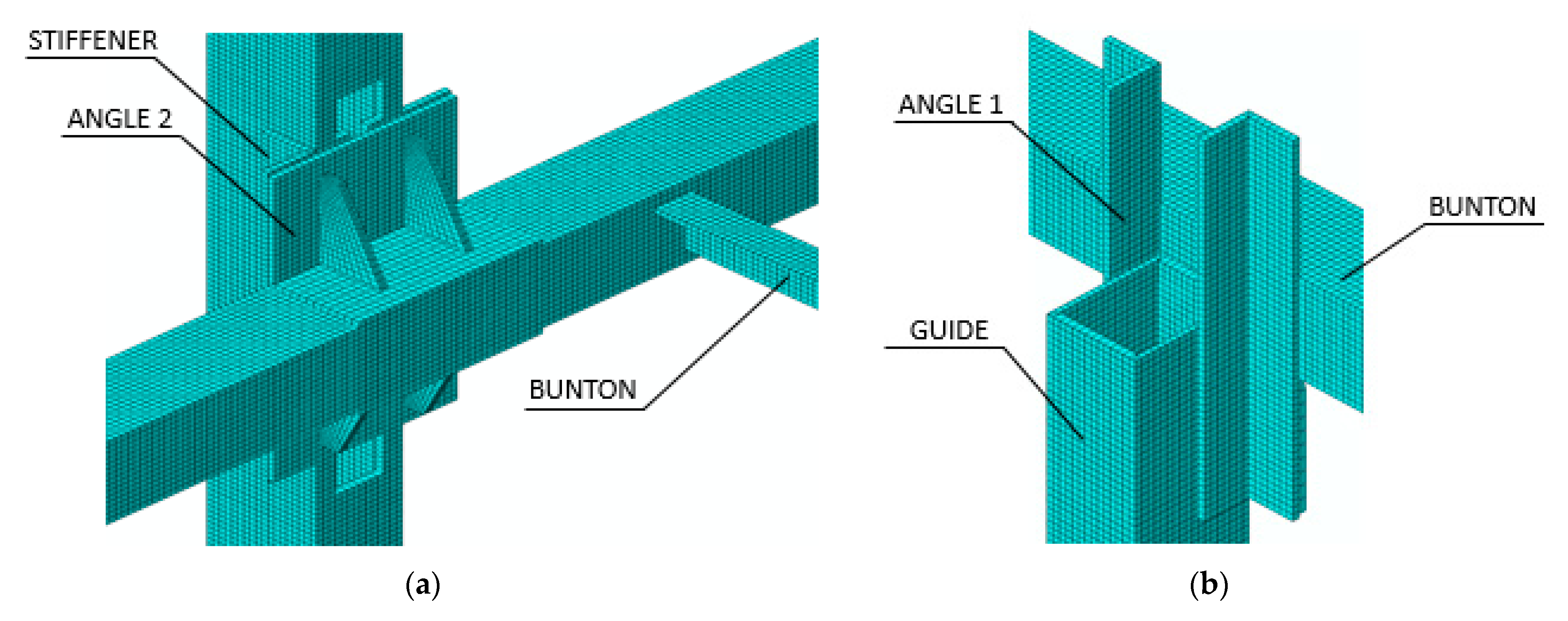
Figure 6 provides the details regarding the connection between the bunton and the guide, and
Figure 7 shows views of the model.
Table 1 lists the geometrical features of the steelwork structure’s components represented in the model.
The spacing and diameter of holes and the dimensions of bolts can have a considerable impact on results for the load-carrying capacity if a connection failure is observed. However, the purpose of the model applied and presented here was to reflect connection stiffness only. The direct representation of a connection by modelling detailed geometry of bolts and welds would be pointless and make the model unnecessarily complex. Therefore, simplified interactions between the nodes of the components to be joined were applied. For welded joints, no displacements and rotations of connected nodes in the weld were allowed (tie constraint). For bolted connections, relative displacements of the nodes of the connected components were limited (pin constraint). The free ends of the buntons were fixed, which corresponds to their being fixed in cast iron brackets anchored to the shaft support. Hard contacts and a friction coefficient of 0.2 were introduced between the surfaces of the sections forming a bond [
22,
23,
24]. The model was loaded with forces acting along a line of winch and dynamometer, in accordance with the in situ testing schemes (
Figure 5).
Six load simulations were carried out in Abaqus following the field-testing diagram. They facilitated the estimation of displacement and rotations values in the model corresponding to the measurements recorded during shaft tests. The static, geometric, and material nonlinear FE analysis was employed.
2.3. Comparison of Field and Numerical Test Results
To compare the results of simulations and field measurements, the force vs. horizontal displacement and force vs. cross-section rotation characteristics were plotted for six load cases (load cases A, B, and C for each of the two series).
Figure 8 shows the force vs. horizontal displacement graphs for tests and simulations in scheme A.
Figure 9 shows the force vs. rotation characteristics on both sides of the half-length guide connection to buntons according to test scheme B. Both simulation results and in situ measurements are presented.
Figure 10 shows the force vs. rotation and force vs. displacement characteristics according to test scheme C measurements and simulations.
A comparison of measurements in the shaft and numerical simulations indicates strong agreement between the obtained results. Deformation characteristics for in situ testing show small variations around the linear trend, which may be explained by clearance levelling in the dynamometer and bolted connections but have a negligible impact on the results of the simulation. Displacement and rotation characteristics show strong agreement between experimental and model characteristics, which indicates that the model properly reflects the structure’s stiffness and response to loads.
4. Discussion
The steelwork load tests we carried out in the mine shaft showed that connections exhibited considerable stiffness. There are strong grounds to represent the bunton-to-guide joints in design and maintenance models as semi-rigid connections. However, current design practices and standards [
16,
17,
18] treat the guide-to-bunton connections as pinned. This leads to simplified calculations and increased design bending moments (over a third increase for the considered steelwork). This practice may be justified by the assumption that the connections degrade due to corrosion. However, to the best of our knowledge, no other studies have attempted to determine the effect of corrosion on the stiffness of these connections. Design procedures take the corrosion effect into account by assuming a corrosion allowance for guides and buntons. A further reduction in structure stiffness due to the same phenomenon may be redundant. Daily visual check-ups of the shaft, as well as legally required periodic inspections, aim to maintain the steelwork, including its connections, in good condition. Taking the stiffness of connections into account leads to reduced design bending moment and guide displacements, resulting in reduced thickness of designed walls or longer design working life, despite corrosion loss of the profiles. Nowadays, it does not make the design computations inadequately complex when using the available tools for structural analysis.
The FE model used for numerical analysis was built on the basis of design documentation of the shaft, materials data, and site inspection. Test loads of the structure carried out in the shaft allowed us to validate this model and the applied simplifications. The comparison of measurements in the shaft and FE simulation results shown in
Section 2.3 indicated a strong agreement between the behavior predicted by the model and that of the structure.
Within the analyzed load range, the guide-to-bunton connections showed linear force–rotation and force–displacement relationships. Some minor nonlinearities for in situ testing were observed, but the general linear tendency was clear and aligned with the model’s response.
The modal analysis provided information concerning the natural frequencies and mode shapes. The high natural frequencies (31 and 35 Hz) indicated the considerable stiffness of the structure compared to other hot-rolled profile constructions, which are usually characterized by a greater span of elements (e.g., four times greater for typical industrial facilities) at a similar bending stiffness. Batko and Korbiel [
25,
26] conducted an experimental modal analysis in a copper mine shaft where the span of guides between the buntons was 1.5 m, and the first natural frequency of the shaft steelwork measured in such conditions was less than 80 Hz [
25,
26]. Given the difference in stiffness stemming from a smaller bunton span and profile, this value is consistent with the values obtained via the numerical simulation presented here.
The value of the dynamic DAF (1.90 for face force and 1.89 for side force) corresponds to the conveyance–guide interaction mode, similar to the one provided by slipper plates [
16]. Under normal operation using guide rollers with shock absorbers [
28,
29,
30], the force does not increase in sharp steps. However, should the guide roller fail, their task is taken over by the steel slipper plates. For roller guiding, which dominates in Polish mines, this condition corresponds to emergency operation; however, in practice, it occurs fairly often and can last for a long duration.
Our results indicate that carrying out non-routine tests and analyses of the shaft steelwork enables significantly more accurate representations of the behavior of the shaft steelwork structure. Enhanced assessment of the structure behavior reduces uncertainty in the design load, thus improving the reliability and safety of structures.
Further research will be carried out to quantify the effect of corrosion loss on the capacity of shaft steelwork guides and buntons, loads, and reliability of steelwork structures.
5. Conclusions
Here, we presented novel experimental and numerical investigations of the stiffness and dynamics of a mine shaft steelwork structure. Stiffness was tested under mining conditions by applying a static load to the structure and measuring deformations. Our tests indicated that the guide-to-bunton connections exhibit considerable stiffness and can be treated as semi-rigid joints. The FE numerical model built on the basis of collected data concerning the structure, geometry, and material of steelwork was successfully validated based on the results of in situ tests of structure behavior. Using linear modal analysis, the natural frequencies and mode shapes of the steelwork structure were calculated as 31 and 35 Hz in the face force and side force directions, respectively. Non-linear dynamic and static FE analyses indicated high dynamic amplification factor values. The current practice and regulations of shaft steelwork design consider joints as pinned, do not take their stiffness into account, and disregard dynamic factors. Our tests and simulations indicate that the omission of these features in the design model results in the incorrect assessment of the design load and ultimately over- or under-sized structures. This can lead to shortened design working life or failure.


