1. Introduction
A thermosyphon is a loop where its internal working fluid can circulate naturally. In a thermosyphon, the working fluid density varies with the desirable arrangement of the heating section and the cooling section. This can generate buoyancy to drive the working fluid to circulate and achieve heat transfer. The heating section and cooling section are usually placed on the bottom and top or left and right sides of the thermosyphon, respectively. The heating in the heating section reduces the working fluid density, resulting in thermal buoyancy. Therefore, the working fluid flows upward and then dissipates thermal energy in the cooling section. When the fluid flows upward and downward (that is, away from the ground or toward the ground), gravity prevents or promotes the movement of the working fluid, respectively. They do not require external driving power; therefore, thermosyphons can be operated reliably. Due to its self-regulating mechanism and stability, thermosyphons can be widely used in various practices, such as solar heating and solar cooling [
1,
2], reactor coolers in nuclear power [
3,
4], geothermal power plants [
5], waste heat reuse devices [
6], electronic cooling solutions [
7], etc. When designing a thermosyphon with good thermal efficiency, many factors need to be considered, including the working fluid types, the wall material characteristics, the location of the heating and cooling sections, and the geometric parameters of the loop, etc. [
1,
8,
9,
10].
The thermal performance of a thermosyphon can be possibly improved through incorporating latent heat effects as the working fluid in the loop changes phase. Currently, it is a valued topic to apply phase change material (PCM) in the working fluid to enhance the heat transfer efficiency of the thermosyphon.
Suspended PCM particles (PCM slurries or suspensions) added into the working fluid in a thermosyphon loop absorb and release latent heat at specific locations. This mechanism can hopefully be used to decrease the temperature at the heating part of a thermosyphon, as well as enhancing its overall heat transfer performance. PCM particles in the suspension can be prepared by microencapsulation [
11,
12,
13,
14] and emulsion [
15,
16] processes. The microencapsulation technique encapsulates a PCM with a polymeric material to separate the dispersion phase (PCM) and the dispersion medium (e.g., water and glycerol) and thereby suspend the PCM particles in the dispersion medium. Microencapsulation is advantageous because the PCM particles prepared using this technology have relatively fixed size and shape and stable physical properties. However, it is costly and difficult to implement. In addition, the polymer material covering the surface of the PCM reduces the heat transfer efficiency of the PCM, and may expand or crack after repeated heating/cooling. In contrast, the emulsion technology uses a suitable emulsifier to reduce the surface tension between the dispersed phase and the dispersion medium, so that the PCM is uniformly suspended in the dispersion medium in the form of particles, thereby forming a stable emulsion. Comparatively, the emulsion technique is relatively low-cost and can easily facilitate large-scale production. From an economic perspective, the emulsion technique is more suitable for industrial development to improve the heat transfer properties of working fluids.
In forced convection, many studies have extensively demonstrated that using PCM suspension as a working fluid can enhance heat transfer performance [
17,
18]. On the contrary, the heat transfer research of PCM suspension as the working fluid in natural circulation loops is quite limited. Ho et al. [
19] numerically studied the heat transfer in a rectangular thermosyphon containing PCM suspensions. They found that there exists a state in which the latent heat absorption and release of the PCM suspension can be effectively used as a heat transfer enhancement mechanism, and it is worth unveiling its application through more extensive parameter investigations. On this basis, Ho et al. [
20] conducted subsequent studies to examine the influence of the loop size, the heating section length, and the cooling section height on the heat transfer performance of a rectangular thermosyphon containing suspended PCM particles. They ascertained the parameter combinations (the loop aspect ratio (AR), the dimensionless heating section length (
), and dimensionless relative elevation between the cooling and the heating sections (
) under which the heating and cooling sections achieved the best efficiencies.
Related research [
17,
18,
19,
20] has explored the effect of PCM concentration on natural convection flow, and the results show that higher PCM concentration results in better heat transfer; although they only focus on the heat transfer performance of the heating section. However, when the PCM concentration increases, heat exchange at the cold section (which is required to cool the liquid PCM back to a solid state) is often overlooked.
Our previous study [
20] found that the best heat transfer efficiency can be achieved in the cooling section of a rectangular thermosyphon containing PCM suspension at AR = 1,
= 0.8, and
= 2. However, the pipe wall properties were not taken into consideration. Under the circumstances, the purpose of this paper was to study the effect of pipe wall characteristics (thermal conductivity and wall thickness) on the heat transfer performance of a rectangular thermosyphon containing PCM suspension with the aforementioned geometric configuration, for which little or no information is available.
2. Materials and Methods
Figure 1 shows the investigated physical model in this study. This model was a PCM-suspension-containing rectangular thermosyphon with
(
and
are the horizontal length (width) and vertical length (height) of the loop, respectively). The inner diameter of the loop pipe is
. The loop consists of a heating section, a cooling section, and adiabatic parts between the heating and cooling sections. The heating section (length:
), placed horizontally at the bottom, can provide a uniform heat flux
. The cooling section (length:
), placed vertically on the right side of the loop, keeps a constant temperature boundary
. The height between the centers of the vertical cooling section and the horizontal heating section is
.
For the buoyancy-driven circulating flow of the PCM suspension, the continuum formulation was applied, and the following assumptions were used:
- (1)
The working fluid (PCM suspension) in the loop follows a two-dimensional (axially symmetric), fully expanded and steady state laminar flow;
- (2)
The working fluid is a Newtonian fluid;
- (3)
The effect of viscous dissipation is not considered;
- (4)
Except for the working fluid density in the momentum equation that follows the Boussinesq approximation, the physical characteristics do not change with temperature or concentration;
- (5)
The concentration of PCM particles is evenly distributed in the loop;
- (6)
The heat transfer in the pipe wall is axially symmetrical, and thermal conductivity of the pipe wall does not change with temperature;
- (7)
The change of PCM particle density during the solid–liquid phase transition is not considered;
- (8)
Compared with the overall flow rate of the working fluid, the relative flow rate between the PCM particles and the suspending fluid is extremely low and can be ignored;
- (9)
The supercooling of the PCM particles is not considered, that is, the melting point and freezing point of the PCM particles are the same.
First, the following dimensionless variable is defined:
Based on the above assumptions and the dimensionless variable, the following dimensionless governing equations were obtained:
Momentum equation:
where
for
,
for
, and
for
and
. In addition, the correction factor for the loop length
is incorporated in the buoyant force term of Equation (2) to consider the minor losses in the loop [
21].
Energy equations:
The last two terms on the right side of Equation (4) represent the transport of latent heat absorption/release related to the melting/solidification of PCM particles. A closure for the liquid-phase volume fraction of the particles
is required; therefore, the enthalpy model developed in our earlier studies [
19,
22] was used here to characterize the phase change process of the PCM particles:
The correlation given by Charunyakorn et al. [
23] was used to calculate the Biot number,
, of the particle.
The dimensionless boundary conditions:
- (1)
Outer wall boundary,
- (2)
Inner wall boundary,
r = 1
- (3)
Center of the pipe,
r = 0
In addition, several quantities of interest, obtained from the solution of the governing equation of the problem, are defined in dimensionless form below.
The bulk temperature of the PCM suspension fluid,
, and the mean liquid-phase fraction of the PCM particles,
, at a given cross-section of the loop are calculated, respectively, as follows:
The dimensionless local heat flux
at the inner pipe wall is:
The axial conduction within fluid is assumed to be negligible, so the total heat transfer rate of the steady-state flow through the cooling section between
and
can be derived based on the integral energy balance as follows:
Equation (12) relates the average bulk temperature of the PCM suspension
and the average liquid-phase fraction of the PCM particles
at a given cross-section of the loop with the convection heat transfer rate
. It reveals that
is composed of the transport of the sensible heat (The first item on the right side of Equation (12)) and latent heat
(The second item). The latent heat contribution to the heat transfer of the cooling section
is:
To quantify the efficacy of the PCM suspension as a heat transfer enhancement medium, the effectiveness of the averaged heat transfer enhancement,
, at the cooling section is defined as follows:
Numerical Method
The differential equations were spatially discretized on a uniform grid, which was placed on the loop that combined the QUICK scheme [
24] for the convection terms and the second-order central difference scheme for the diffusion term. The line successive over-relaxation method was used to calculate the unknown terms. In addition, the tridiagonal matrix algorithm was applied to solve the problem by iterating along the main flow direction s
+ starting from s
+ = 0 (
Figure 1). The ratios of the maximum change of temperature, liquid phase volume ratio and flow velocity to its highest value were employed for whether each parameter converges or not. The convergence criterion for each parameter was 10
−5.
When testing grid independency, the average Nusselt numbers of the inner pipe walls of the heating and cooling sections were employed to calculate the deviation percentages. The grid convergence index (GCI) method was used to estimate the numerical error by the local Nusselt numbers of the heating and cooling sections. The deviation percentage and numerical error were obtained to decide the number of grid points suitable for the calculation. Our previous study [
20] showed that 2001 × 201 grid cells are sufficient under the assumption that
= 0. Thus, this study increased the number of radial grids on the basis of 2001 × 201 grids.
Grid cell testing is performed for various values under the following parametric conditions: AR = 1; = 0.8; = 2; = 0.1; = 0.6; = 1011; = 10%; and = 0.5. The error in the mean Nu was less than 1% when using 2001 × 701 grid cells. An examination of the energy balance in the pipe wall in the cooling and heating sections (data not shown) also found that the error in the energy balance was less than 1% when using 2001 × 701 grid cells. Thus, 2001 × 701 grid cells were used for all the simulations in this study.
To validate the simulation, the specific case of heat transfer in a single-phase toroidal loop and the forced convection of a circular pipe flow with a PCM suspension were simulated for comparison [
20] with the results that were presented in references [
25,
26]. The result showed that the difference was not significant and acceptable. Therefore, the reliability of the simulations was confirmed.
3. Results and Discussion
This study investigated the effects of the pipe wall properties (thermal conductivity and wall thickness) on the heat transfer performance of a thermosyphon with the recommended geometric configuration (AR = 1, = 0.8, = 2). The parameter ranges were as follows: the modified Rayleigh number was , the wall-to-fluid thermal conductivity ratio was = 0.1–100, and the volumetric fraction of PCM particles was = 0–10%. Other parameters remained unchanged and were set as follows: the PCM particle-to-fluid thermal conductivity ratio was = 0.412, the PCM particle-to-fluid density ratio was = 0.774, the dimensionless radius of particles was = 0.023, the modified Stefan number was Ste* = 0.1, and the modified subcooling factor was Sb* = 0.6.
Figure 2 shows the axial distribution of loop temperature and the average liquid-phase fraction of the PCM particles
under different
values.
is the temperature of the outer pipe wall,
is the temperature of the inner pipe wall,
is the average liquid temperature at the flow section, and
s* is the dimensionless axial coordinate (=
). In this figure, all parts were thermally insulated except for the heating and cooling sections. As shown in
Figure 2a–c, the thicker the pipe wall, the higher each temperature. This is because the increase in
leads to an increase in thermal resistance.
When
= 0.5 (
Figure 2d), the distribution of
shows that increasing
increases the overall temperature, and consequently, as shown in the red area, the PCM particles do not solidify at all.
Figure 3 shows the effects of the
of the pipe wall on the heat transfer performance of the loop when
= 0.1.
is defined as the ratio of the
k of the pipe wall to that of a pure liquid (water) and characterizes the heat transfer capacity of the pipe wall. As demonstrated in
Figure 3a–c, the lower
, the higher the thermal resistance of the pipe wall, and therefore, the higher the pipe wall temperatures. In addition, under the geometric parameters set in this study (
AR = 1,
= 0.8, and
= 2),
= 1 when
< 0.1 at each
value (0.1–0.5), it shows that the PCM particles remained in a liquid form and did not solidify when cooled in the cooling section and therefore lose the chance to absorb latent heat in the following heating section. When there was a phase change, the absorption and release of latent heat resulted in a concave shape in the temperature curve. For example, as demonstrated in
Figure 3c, when
= 0.1, due to a lack of absorption of latent heat, changes in the temperature in the heating section followed a nearly linear pattern. However, when
= 1–100, the absorption of latent heat resulted in nonlinear changes in temperature, as indicated by the area circled by a red dotted line.
As demonstrated in
Figure 4a, with the modified Rayleigh number
= 10
10, increasing
from the theoretical value (
= 0, as indicated by ⯈) to 0.1 (
for thin shells) changed the proportion of latent heat transfer
(as indicated by the area boxed by the red dotted line). When
= 0.1, due to the excessively low heat transfer performance of the pipe wall, the pipe wall of the loop was excessively hot. As a result, the PCM particles were unable to solidify in the cooling section (as indicated by the area circled by the red dotted line in
Figure 4a). Consequently, latent heat was unable to play a role in the cooling section (as indicated by the area highlighted in yellow). When
= 100, increasing
(0.1–0.5) can more effectively use the latent heat of the PCM, even compared to increasing
in the cooling section under the theoretical conditions (
= 0). As shown in
Figure 4b, there were similar changes when
= 10
11 and 10
10.
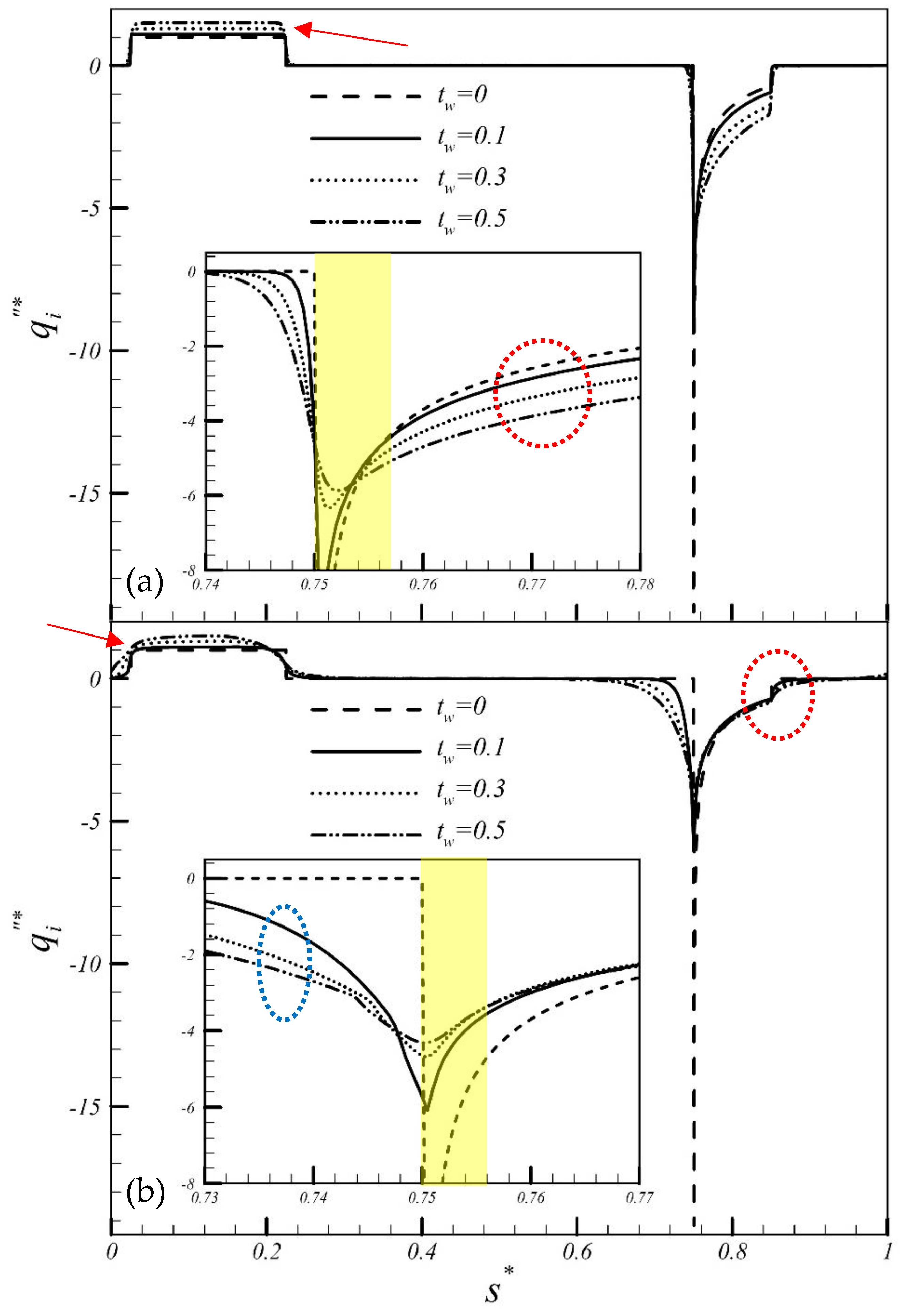
As demonstrated in
Figure 5, at a relatively high
value, a relatively high heat flux was generated in the heating section, as indicated by the red arrow. At the inlet of the cooling section, at a relatively high
value, the maximum heat flux was relatively low. Thus, increasing
can mitigate the peak heat flux (e.g., the yellow highlighted area). However, outside this peak area, increasing
increases the heat flux in the cooling section (e.g., the area circled by the red dotted line). In addition, at a relatively high
, due to the preheating effect by the heating section and the precooling effect by the cooling section, changes in the heat flux curve occur in advance (e.g., the area circled by the blue dotted line). When
= 100 (
Figure 5b), the precooling effect is more pronounced.
Figure 6 shows the variation in the effectiveness of the heat transfer enhancement over the cooling section
with
. Based on the definition of
, a high
value means that the convection heat transfer coefficient in the cooling section of the thermosyphon is relatively high. As demonstrated in
Figure 6a, when
, increasing
can effectively increase
. This
was higher than that under theoretical conditions (
= 0; as indicated by ⯈) when
= 10 and
= 0.1–0.5 and when
= 100 and
= 0.1–0.5. The highest efficiency (
= 1.017) occurred when
= 100 and
= 0.5. When
(
Figure 6b), the higher
, the higher
. The highest
occurred at a moderate
. This occurred because while the flow rate of the fluid in the pipe increases and the fluid can therefore take away more heat when
(e.g., when
= 1,
increases as
decreases), the heat transfer in the pipe wall in the cooling section also exerts a significant impact when
= 100 (e.g., increasing
increases the amount of heat transfer; thus,
increases as
increases; as also demonstrated in
Figure 7). With the balance of these two factors, the highest
(1.068) occurred when
= 100 and
= 0.3.
For the loop with water as its working fluid,
= 1 (marked by the red dotted line in
Figure 6). Here, the working fluid in the loop was changed from pure water to a 10% (volumetric fraction of PCM particles) PCM suspension. Under the operating ranges of parameters used in this study, when
, using a pipe material with a
and a
enhanced the heat transfer performance of the cooling section of the thermosyphon. This approach could increase the heat transfer by up to 1.7% (when
= 100 and
= 0.5) compared to that when water is used as the working fluid. Under these conditions,
Nu = 4.4. In comparison,
Nu = 4.0 when water was used as the working fluid. When
, it is recommended that a pipe material with relatively high heat transfer performance (
) be used to enhance the heat transfer performance of the cooling section. This approach can increase heat transfer by up to 6.8% (when
= 100 and
= 0.3). Under these conditions,
Nu = 5.6. In comparison,
Nu = 4.8 when water was used as the working fluid.
4. Conclusions
This research was a follow-up to our previous research [
20], which used numerical simulation to determine the best geometric configuration (
AR = 1,
= 0.8,
= 2, wall thickness
= 0) for the cooling section of a rectangular thermosyphon containing PCM suspension to achieve the highest cooling effect. This study investigated the influence of the pipe wall characteristics (wall thickness and thermal conductivity) with the above-mentioned recommended geometry on the heat transfer performance of the thermosyphon. The thermosyphon under consideration consisted of a heating section with a constant heat flux along the bottom horizontal branch, a cooling section at the right upper side of the loop with a constant wall temperature, and two adiabatic sections between them. The physical parameters and their ranges related to the present problem were as follows: the modified Rayleigh number was
, the thermal conductivity ratio of the wall to the suspending fluid was
= 0.1–100, and the volumetric fraction of PCM particles was
= 0–10%.
Numerical results reveal that, with proper selection of wall thickness and heat conductivity, the conjugate heat transfer between the loop wall and PCM suspension can lead to further enhancement in the heat transfer effectiveness over the cooling section of the rectangular loop. When and under the parametric conditions set in this study ( = 0.6, = 0.1, and = 10%), it is recommended that a pipe material with a and a can be used to enhance the heat transfer performance of the cooling section. Compared to that under theoretical conditions ( = 0), the heat transfer performance of the cooling section can be improved by 4.0% when = 100 and = 0.5.
When , it is recommended that a pipe material with relatively high thermal conductivity () be used. Compared to that under the theoretical conditions ( = 0), the heat transfer performance of the cooling section is effectively improved by 3.2% when = 100 and = 0.3.
For the loop with a 10% (volumetric fraction) PCM suspension as its working fluid, under the geometric configuration and the parametric conditions set in this study, when and , using a pipe material with ( = 100; = 0.5) and ( = 100; = 0.3) can increase the heat transfer by up to 1.7% and 6.8%, respectively, compared to that when water is used as the working fluid.
The objective of the present study was to investigate the effects of the pipe wall properties (thickness and thermal conductivity) on the heat transfer performance of a PCM suspension-containing rectangular thermosyphon. Further efforts that provide insights into the comprehensive parameter ‘thermal activity’ (: pipe wall thickness), for which no information was considered, are very important and have to be made. This is not what we are exploring in this study, but is worthy of further consideration.


