Article

On the Possible Introduction of Mini Gas Turbine Cycles Onboard Ships for Heat and Power Generation

Department of Mechanical, Energy, Management and Transportation Engineering, University of Genoa, 16145 Genoa, Italy
*
Author to whom correspondence should be addressed.
Energies 2021, 14(3), 568; https://doi.org/10.3390/en14030568
Submission received: 11 December 2020 / Revised: 14 January 2021 / Accepted: 18 January 2021 / Published: 22 January 2021

Abstract

:
The recent coming in force of MARPOL 2020 restrictions on shipping pollutant emissions highlights a growing interest in current times towards cleaner means of transport. One way to achieve more sustainable vessels is represented by updating onboard engines to suit current regulations and needs: Gas Turbines are not a novelty in the field and, despite the few applications in commercial shipping so far, this technology is again under evaluation for different reasons. Indeed, it is still a preferred choice in navy, where swift maneuvering is a key factor; it is employed by fast ferries and hydrofoils for its high power/weight ratio; it has been recently applied to LNG carriers to burn boil-off gas in a more efficient way and several studies in literature suggest its possible introduction on large Cruise Ships. Since there seems to be a lack of research concerning small size units, the present work attempts to evaluate the possible usages of Mini Gas Turbine Cycles in the range of 1 to 10 MW of electric output for heat and power generation onboard commercial vessels dedicated to passenger transport. For this purpose, a statistical analysis on existing operating vessels up to 2020 was made, to eplore main engine sizes; a literature review was carried out to find representative onboard heat demands. Once the main vessel electrical and thermal requirements were evaluated, Mini Cogenerative plants based on Gas Turbines were designed within the identified boundaries and compared with state-of-the-art Marine Diesel Engines and Gas Turbines on estimated global performance, dimensions and weights.

1. Introduction

A worldwide attention is focusing nowadays on transport systems, looking for more energy efficient and sustainable means of transportation [1]: in the field of navigation, January 2020 saw MARPOL Annex VI [2] convention coming in force, with the aim to significantly reduce pollutant emissions of Nitrogen and Sulphur oxides (NOX and SOX) onboard ships [2,3]. Such goals can be achieved by installing more efficient power plants: among the possible solutions, gas turbines represent a promising choice, as these machines need to run on clean fuels, such as Sulphur-free liquified natural gas (LNG), and allow for better combustion temperatures control-compared to current internal combustion engines (ICE)—to reduce NOX pollutants. Already tested for commercial applications in the early 2000s [4], gas turbine onboard plants have shown performances comparable to current marine engines [4,5,6,7,8], reaching 50% electrical efficiency with a combined cycle for electric-drive propulsion. Applications of gas turbines (GT) as prime movers can be found mainly in navy [5,7,9] and LNG carriers [8,10,11,12]: the former ones are justified by the need for swift maneuvering, thanks to the limited transient times associated to GTs [5,7]; the latter rely on the possible usage of boil-off gas (BOG) in the main engine, instead of re-compressing it, along with some savings in onboard space-allowing for more cargo capacity [8,10,11]. Multiple studies in the field suggest that the introduction of such plants on ferries and large cruise ships [9,11,13,14] would allow for competitive efficiencies with space savings-depending on several design choises: a thoughtful selection in Heat Recovery Steam Generator (HRSG) type and layout could improve space [5], engine comparisons could be made to find the best combination of components and reduce weight [15], while vessel emissions are mainly subjected to fuel type and engine efficiency [16], to avoid introducing further components for exhaust gas treatment. However, while there are examples of studies concerning the feasibility of gas and steam turbines (ST) as main or auxiliary engines [13,14,15] and possible improvements to waste heat recovery through such machines [17,18] on large ships with high energy and power requirements, there seems to be a lack of similar work on smaller size GT units. Usually, compact turbomachines are mainly considered for ICE turbocharging, with niche applications for power generation [19]. We call Mini Gas Turbine Cycles [20] the GT-based energy generation systems, which are suited for ratings in the order of magnitude of 1 or a few electric MW (MWel). Thus, the present paper attempts to define the possible applications, advantages and limits of Mini Gas Turbine Cycles for heat and power generation onboard commercial and passenger ships. To assess this topic, a review of currently operating worldwide vessels is made, in order to define a suitable engine size; a literature review concerning energy and heat requirements onboard cruise ships is performed, with the aim to investigate the magnitudes of onboard heat and electric demands; finally, different plant architectures for Combined Gas and Steam Cycles are compared within the boundaries defined by the previous analysis, to determine the best options in terms of performance, size and weight. A comparison with current naval prime movers - both Diesel engines and marine Gas Turbines at state of the art - is made, to show the possible advantages of the proposed solutions.

2. Analysis Methodology and Modeling

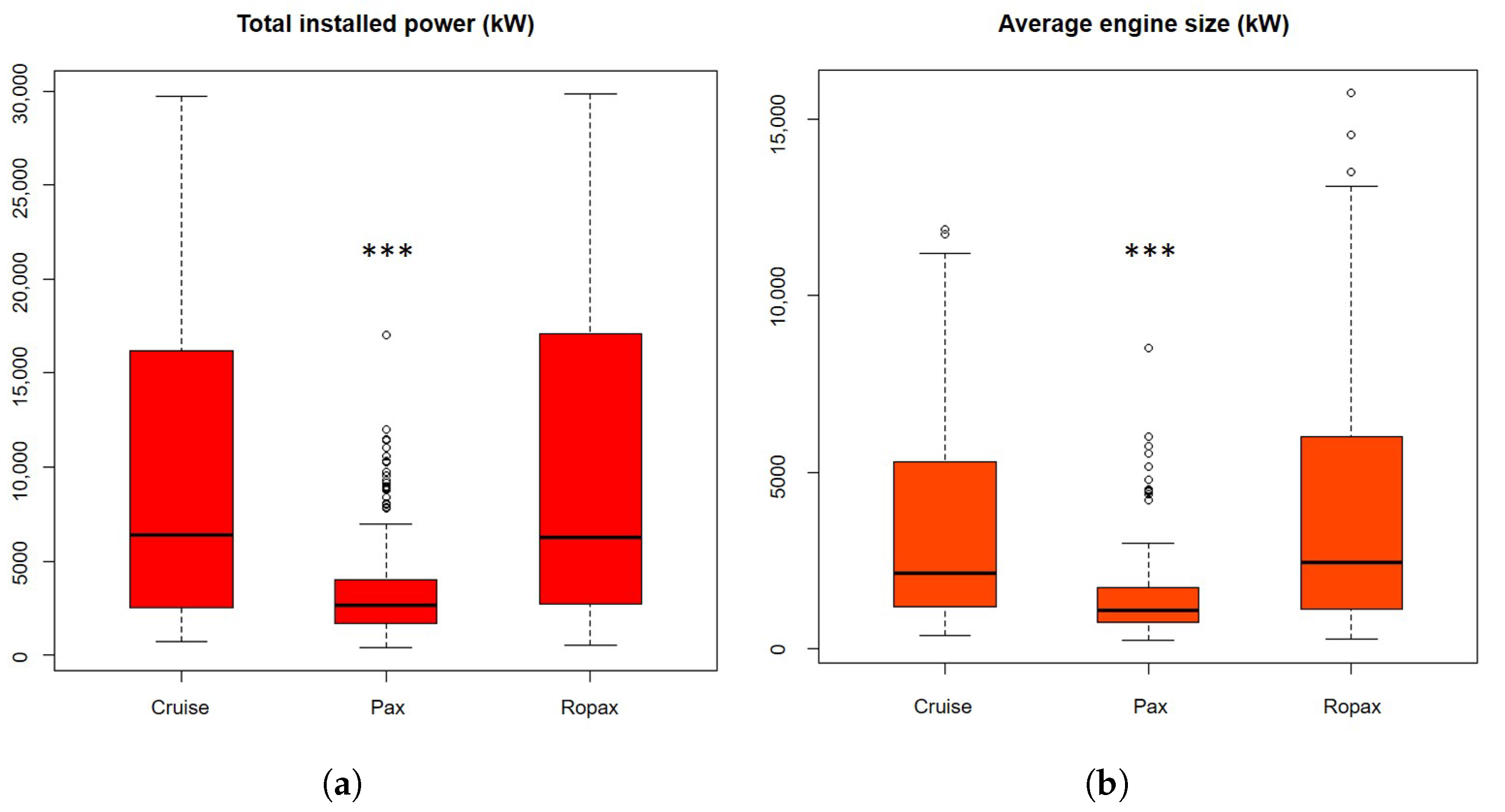
2.1. Worldwide Ships Statistics

With the aim to perform statistics on a representative sample of actual operating ships, data from SeaWeb Database [21] were extracted on worldwide vessels registered from 1980 to 2020 for Cruise, Ro-Pax and Passenger ship types. Restrictions on total installed power and passenger number were chosen, to select main engines of relatively small size, but still with non negligible heat requirements. Database characteristics and filter limits are summarized in Table 1: here, Gross Tonnage (GT) indicate a conventional measure of ship size, being related to the internal volume of vessels. The acquired data were checked, in order to remove all non-operating vessels, missing information or mistakes.
Figure 1 describes the two variables chosen for statistical analysis: total installed main engine power and an average engine size, defined respectively as the sum of the nominal power of all engines onboard and the arithmetic average based on the number of main engines. Statistical analysis was performed by the program R, described in [22]; significance level was set to p < 0.05. Since none of the data arrays was normally distributed (Lilliefors; p < 0.001), non parametric Pairwise Wilcoxon test was performed for comparison between ship types. Passenger vessels were found to be significantly different to both Cruise and Ro-Pax (Wicoxon; p < 0.001), while no significative differences were found between Cruise and Ro-Pax vessels. From these findings, it was chosen to focus only on Cruise and Ro-Pax ships, in the following steps. The graphical outliers in Figure 1 were further checked, to avoid data inconsistency: the Cruise ones represent vessels from a specific company, Marella Cruises (Luton, UK), which have slightly larger engines installed compared to the rest of the database; Ro-Pax graphical outliers represent the fleet of MOL Ferry Co. (Tokyo, JP), a japanese ferry company which delivers high-speed travel through the islands of Japan, thus needing power to reach speeds up to 35 knots; finally, Passenger vessels graphical outliers were also checked, but no mistaken or missing data were found. For this last ship type, it was concluded that the scattering of the distribution is related to how different design solutions can be chosen for varying transport needs.
Statistics are summarized in Table 2: medians were chosen as representative values for both variables, being more robust for non-normal distributions; a confidence interval with 95% accuracy was also defined, based on the distribution quantiles calculated in the program R [22].

2.2. Energy Analysis on Cruise Ships

An analysis of cruise ship onboard energy demands was necessary to determine a representative heat requirement, to be related with the characteristic engine sizes found. An intensive literature research led to the energy consumptions summarized in Table 3, including the first application of Gas Turbines in commercial shipping [4], representative models [23] and energy and exergy analyses on actual operating ships [17]. The available material in literature is mainly related to cruise ships, as these vessels have the highest variety of energy demands for heat, mechanical and electrical power; moreover, such analyses are mostly concerned with large cruise ships [24,25], with the exception of MS Birka Stockholm [26,27]. To test the possible usage of a COGES layout (COmbined Gas Electric and Steam), mechanical power for propulsion has been considered along with pure electrical demands for onboard needs, such as ship services and lighting. The last row of Table 3 reports the chosen indicator, which is the ratio between heat requirements and the total electrical power that should be provided by main engines to satisfy propulsion and electrical needs. A relatively large window was observed for this parameter: following a similar approach as in Section 2.1, 0.51-the exact median of this distribution-would be a representative value, but 0.54 was chosen as design parameter for the following steps. Indeed, the median refers to a theoretical model, while 0.54 was taken from an actual running cruise vessel. This value was judged to be sufficiently close to the median in order to represent the calculated distribution; moreover, it refers to the smallest ship found in literature references-having a total main engine nominal power of 23.4 MW. From further analysis on this vessel [26,27] it was possible to gather a more detailed description of the heat demands arrangement: 90% of power is supplied to the air conditioning system and 10% to onboard heat services — 7% via high pressure (HP) steam and 3% via low pressure (LP) steam. All data concerning heat fluxes were normalized with the maximum heat required, in an attempt to generalize the available information gathered from literature. Service steam typical pressures were found to be around 9 bar (HP) [4] or 2 to 6 bar (LP) [26,27], usually collected from a steam power turbine fed with a maximum pressure of 32 bar [4,14]-through bleeding, or directly at the turbine exhaust. Finally, since the chosen value for heat to power ratio refers to a typical winter day sailing, sea water and ambient temperatures were also established according to the season.

2.3. Gas and Steam Cycles

The previous analysis from Section 2.1 highlighted an operating range of about 1 to 10 MWel per unit. Willing to design compact solutions, it was chosen to focus on radial architectured GTs rated for net electrical power outputs of 2.5 and 5.0 MW. The employment of a machine of size specifically designed for the present application, based on a radial architecture, it is expected to allow achieving competitive performances while still preserving compactness—especially concerning axial lenght—when compared to current existing commercial marine diesel engines and axial gas turbines of similar overall power. Power plants were analyzed from the simplest scheme to the most complex COGES layout, as listed below.
  • (SC)—Simple cycle GT with WHR
  • (RC)—Regenerated GT with WHR
  • (CC back P)—Backpressure Gas and Steam Combined Cycle-COGES (A) and (B)
  • (CC cond)—Condensing Gas and Steam Combined Cycle-COGES (A) and (B)
All solutions were designed for both 2.5 and 5.0 MW of rated electrical power, with steam generation from the exhaust gas residual enthalpy, to satisfy heat demands according to Section 2.2. A COGES layout for backpressure configuration and a second one allowing for condensation at subatmospheric pressure were calculated. Moreover, COGES (A) and (B) in the list correspond to two different philosophies: in case (A), 2.5 or 5.0 MWel are the sizes of the COGES plant (GT + ST net output), while in case (B) the power requirements of 2.5 and 5.0 MWel are provided by the gas turbine alone and the bottoming steam cycle generates further electrical power, determining a larger global size of the plant. In-house developed codes were used for both thermodynamics and plant calculations, employing NASA libraries [28] for gas and steam properties. A summary of common parameters for design is presented in Table 4.
In order to account for size effect on turbomachinery, ranges of total-to-total efficiencies were chosen for state-of-the-art compressors, gas and steam turbines, to be set automatically in the code as functions of electrical power. Following the analysis of Section 2.2 and a previous sensitivity analysis of gas cycle parameters from [20], it was concluded that a pressure ratio of 6 would be the best value to maximize onboard power and heat generation, as the heat available at the exhaust is expected to be much higher than the services to be satisfied. Steam temperatures and pressures were chosen to suit cruise vessel needs-according to Section 2.2—while maximum steam pressure was set to 40 bar, as a compromise between the trend observed for onboard cruise vessels and the need for higher efficiency of the steam cycle. Steam and gas cycle maximum temperatures were chosen considering the state-of-the-art limits on the mechanical resistance of the materials needed to manufacture such turbomachines. Loss coefficients to account for pressure drops due to heat exchangers on both gas and steam sides were adopted.

2.4. Components Weight Estimation and Sizing

Component weight was estimated following a method proposed by Rivera-Alvarez et al. [15]: the described model was updated with data on heat exchangers for marine applications and recalibrated on commercial radial gas turbines. The resulting model relations (1)–(5) were derived, with the set of parameters listed in Table 5:
M G T = k G T · ( m ˙ G T ) 3 / 2 + M G T , 0
M S T = k S T · ( m ˙ S T ) 3 / 2 + M S T , 0
M G E N = k G E N · P e l + M E G , 0
M H R S G = k H R S G · A H R S G + M H R S G , 0
M C O N D = k C O N D · A C O N D + M C O N D , 0
An estimate of machinery and component dimensions was carried out, to compare overall size and mechanical limits concerning rotating parts: rotor preliminary design was performed starting from classic statistical diagrams in literature [29], which allowed to fix a value of specific speed for all radial compressors, corresponding to the maximum predicted component efficiency— n s = 0.75, following its definition as in Equation (6). Calculated mass flow rates, densities and specific work were used to determine rotational speed for each case; this value was kept constant in order to calculate specific speed on the matching turbine, which allowed to define whether the designed machine would be of radial or axial type. Rotor maximum diameters were finally calculated assuming straight radial blades for both turbomachines, considering the ideal work exchange and accounting for slip factor effect on all compressors.
n s = 2 π n 60 · m ˙ ρ o u t 1 / 2 l i d 3 / 4

3. Results

The following subsections describe the obtained results, in terms of cycle performance, turbomachinery design, weight and overall dimensions. All values are compared with state-of-the-art marine Gas Turbines and Diesel engines: in particular, models from Wärtsilä ranging from 2.5 to 6.0 rated MWel were chosen [30], along with GE commercial 4.6 MWel [31], Zorya-Mashproekt UGT-3000 (3.3 MWel) [32] and Rolls Royce Allison 501-KF (3.2 MWel) [33] Gas Turbine gensets.

3.1. Plant Performance Comparison

Table 6 and Figure 2 present results for gas turbine exhaust mass flow, turbine outlet temperature (TOT) and the calculated efficiencies for the selected Mini Gas Turbine cycles. Within the boundaries described earlier, combined cycles were found to be the most efficient GT options-reaching electrical and CHP efficiencies up to 35 and 55%, respectively, in the simulated operating conditions.
Results were compared with state-of-the art engines for which data could be retrievied: CHP efficiencies were calculated assuming the same boundaries described in Section 2.2. Data were retrieved for typical engine operating conditions—i.e., 85% load and ISO intake air-from official brochures and technical manuals available from manufacturers. It can be seen that the Mini Gas Turbine based power plants achieve CHP efficiencies, comparable to the ones calculated for commercial Gas Turbines. The examined Diesel Engines show higher overall efficiencies compared to the rest: however, it has to be noted that while benefiting from high electrical performance, in the given design boundaries none of the examined engines could satisfy the entire heat demand alone, due to lower exhaust temperatures and higher minimum funnel temperature-set to 150 C to avoid acid condensing in the stack, when burning conventional fuel. The same finding applies when considering dual fuel engines: despite allowing for lower funnel temperature and higher exhaust temperatures, the increase in available Δ T is not sufficient. The share of heat missing varies from 200 to nearly 2000 thermal kW (kWth) and it was modeled by introducing an auxiliary boiler with a component efficiency in line with industrial state-of-the-art practice [34]. The usage of exhaust boiler(s) is expected to be even more severe, when considering part-load operation during sailing; on the other hand, Mini Gas Turbines are normally affected by a decrease in electrical efficiency in off-design conditions, which is likely to help satisfying onboard heat demands by raising temperatures at the Turbine exhaust. To highlight this potential, Figure 2b reports the highest CHP efficiencies achievable by marine Gas Turbines, if assuming that all exhaust heat can be recovered and used for onboard service, within the boundaries of the present work. These values can reach 73% for Combined cycles in backpressure configuration and 83% for SC Gas Turbines with WHR; Condensing Gas and Steam Combined Cycles, however, would not benefit much from further heat recovery, as condenser temperatures are too low for practical use in cogeneration. Finally, it is of some interest to point out how close the calculated actual CHP efficiency and the achievable maximum for a Regenerated GT Cycle are: even if onboard heat requirements are fully satisfied by the proposed plant, the internal regeneration strongly limits exhaust heat recovery by reducing temperatures at the turbine outlet, leaving little room for further improvements in overall performance-at least for cogenerative applications.

3.2. Component Sizing

All the explored Mini Gas Turbine cycles were found to be suitable for radial components, except for the regenerated one: a mixed architecture with radial compressor and axial turbine is recommended. Its detailed design is expected to be difficult, as it is necessary to maintain compactness for such high rotational speeds, in order to avoid mechanical failures-leading to potentially unrealizable axial turbine blades.
All data concerning the component preliminary design are summarized in Table 7. All machine rotational speeds, required to match the set values of ns,c tend to concentrate between 20’000 to 30’000 rpm, decreasing with electrical power. The only exception is represented by regenerated cycle turbogas, which needs higher rotational speed compared to the rest, as the compressor has to compensate the additional loss imposed by the heat exchangers.
Overall dimensions were derived from similar radial GT simple cycle packages on the market-with particular focus on Opra Turbine’s OP16 [35]: areas of (6.47 × 2.44) m2 and (7.44 × 2.70) m2 were found for, respectively, 2.5 and 5.0 MWel single cycle power units. The increase in component sizes with respect to the OP16-(6.06 × 2.44) m2—is related to the higher power output of the proposed solutions. A comparison with overall size of state-of-the-art naval engines is presented in Figure 3, where it can be clearly seen the advantage in space savings amongst nearly any Diesel engine of the same power which was analyzed. Overall dimensions for the Mini Gas turbines refer to a complete enclosed package, including engine, gearbox, electrical generator, auxiliary equipment and access space. Mini Gas Turbines engines alone are not supposed to exceed 2 m in width, considering also air intakes.

3.3. Component Weight

Figure 4 summarizes the calculated and retrieved data for Mini Gas Turbine, naval GT and Diesel engines considering (a) engines alone, (b) the genset packages and (c) a full plant, comprehensive of all main components and heat exchangers. Calculated weight for Mini Gas Turbines was found to be similar, only slightly higher than commercial Gas Turbines, while being much lower than the weight of all Diesel engines analyzed. The maximum weight achieved with the calculated Mini Gas Turbines was 70 tons for a combined cycle of (B) type with condenser, being the one with the largest number of components and with greatest heat exchangers. Diesel engine weight represented in Figure 4c is just the sum of the weight of the genset package and that of the heat exchangers according to the adopted model [15]; the weight increase brought by heat recovery systems is limited to 4 to 8 tons approximately, as the available energy to be recovered is relatively low, if compared to the GT cases. The complete plant weight should include also auxiliary boilers and related components, but this detail falls above the objectives of the present work.

4. Conclusions

Given the growing interest for more efficient and environmentally friendly means of transportation, an effort was made to assess whether Mini Gas Turbine cycles could play a role as a valuable choice for onboard energy generation systems on medium size Cruise and Ro-Pax vessels. Results showed that Mini Gas Turbine cycles achieve competitive cogeneration performance if compared to commercial Gas Turbine and Marine Diesel engines, despite the lack in electrical efficiency. GT-based solutions allow to satisfy the entire onboard heat requirement by recovering energy from exhaust gases; instead, Conventional Diesel engines require additional boilers and equipment, with a consequent increase in occupied space and weight. Moreover, since the heat available at the GT outlet is higher than the one from Diesel Engines of comparable size, CHP efficiency increases with heat demand, as illustrated by the maximum achievable values in Figure 2: if we consider the highest ratio defined in Section 2.2 of 0.65, CHP efficiency can raise by 2–3 points for the combined cycles architecture. It is also worth mentioning that the maximum theoretical heat available for recovery at the Mini GT exhaust can reach up to 11 MWth for the highest design ratings. This value exceeds the heat requirements reported in Section 2.2 for all considered vessels, except for Norwegian Epic; however, the size of such ship puts it beyond the expected applicabilty of the proposed Mini Gas Turbine Cycles. Further improvements on Mini Gas Turbine performance can be made by raising steam maximum pressure, increasing CHP efficiency of other 1–2 points for maximum steam pressures of 60 to 80 bars, allowing performances near to 60%. Multiple pressure levels for steam production were not considered, given the desire to propose solutions as compact as possible for onboard heat and power generation. Finally, improvements in plant overall efficiency could be brought by simultaneous generation of electricity, heat and cooling (CHPC), introducing additional chillers powered by low temperature residual heat; this solution, despite being interesting for the application on commercial vessels, falls beyond the aim of the present work.
Another advantage of employing Mini Gas Turbines onboard is related to space savings: with respect to Diesel Gensets, Mini Gas Turbines can be 20% shorter than conventional engines for 2.5 MWel output and up to half the length of a Diesel Genset for 5.0 MWel size. Calculated gensets dimensions proved also to be similar to commercial GTs, while showing better CHP efficiencies. Finally, a big difference was observed in terms of weight, which, for Mini GT configuration, was drastically lower than Diesel engines and comparable to commercial Gas Turbines: around 20 tons less for gensets configuration, up to 80 tons when considering heat exchangers at the exhaust. Reduced weight and dimensions represent an opportunity to increase shipping efficiency by having lighter vessels and thus introducing more cargo or passenger cabins [4,5,10], while still employing an efficient prime mover.
Possible updates on this research topic lie in the statical analysis, which might be extended to all vessels worldwide, detailed design of components, onboard plant layout and evaluation of Trigeneration onboard cruise ships.

Author Contributions

Conceptualization, D.B., M.L., F.S. and P.Z.; Formal analysis, D.B., M.L. and F.S.; Investigation, D.B., M.L. and F.S.; Writing, D.B., M.L., F.S. and P.Z. All authors have read and agreed to the published version of the manuscript.

Funding

This research received no external funding.

Conflicts of Interest

The authors declare no conflict of interest.

Abbreviations

The following abbreviations and symbols are used in this manuscript:
back PBack Pressure
BOGBoil-Off Gas
CCCombined Cycle
CHPCombined Heat and Power
CHPCCombined Heat, Power and Cooling
COGESCOmbined Gas Electric and Steam
condCondensing
DDiameter
η c compressor isentropic efficiency
η c c combustion efficiency
η g e n generator efficiency
η m mechanical transmission efficiency
η p pump isentropic efficiency
η t turbine isentropic efficiency
GTGas Turbine or Gross Tonnage (ships)
HPHigh Pressure (steam)
HRSGHeat Recovery Steam Generator
ICEInternal Combustion Engine
lSpecific work (per unit mass)
LCVLower Confidence Value
LHVLow Heating Value
LNGLiquified Natural Gas
LPLow Pressure (steam)
M / ṁM: mass / ṁ: mass flow rate
MWel / MWtheletric (el) / thermal (th) MW
n / nsn: rotational speed / ns: specific speed
psignificance level
PelNet electric power output
PaxPassenger vessel
QQuartile
ρ Density
RCRegenerated Cycle
Ro-Pax(also Ropax) Roll-on / Roll-off vessel for vehicles and passengers
SCSimple Cycle
STSteam Turbine
TTemperature
TITTurbine Inlet Temperature
TOTTurbine Outlet Temperature
UCVUpper Confidence Value
WHRWaste Heat Recovery

References

  1. Carlton, J.; Aldwinkle, J.; Anderson, J. Future Ship Powering Options: Exploring Alternative Methods of Ship Propulsion; Royal Academy of Engineering; Prince Philip House: London, UK, 2013; ISBN 978-1-909327-01-6. [Google Scholar]
  2. Resol. MEPC.176(58). In Amendments to the Annex of the Protocol of 1997 to Amend the International Convention for the Prevention of Pollution From Ships, 1973, as Modified by the Protocol of 1978 Relating Thereto—Revised MARPOL Annex VI; Adopt 10 October 2008; IMO: London, UK, 2008. [Google Scholar]
  3. Resol. MEPC.177(58). In Annex 14, Amendments to The Technical Code on Control of Emission of Nitrogen Oxides from Marine Diesel Engines-NOX Technical Code 2008, Mepc 58/23/add.1; Adopt 10 October 2008; IMO: London, UK, 2008. [Google Scholar]
  4. Sanneman, B.N. Pioneering Gas Turbine-Electric Systems in Cruise Ships: A Performance Update. Mar. Technol. 2004, 41, 161–166. [Google Scholar]
  5. Haglind, F. A review on the use of gas and steam turbine combined cycles as prime movers for large ships. Part I: Background and design. Energy Convers. Manag. 2008, 49, 3458–3467. [Google Scholar] [CrossRef]
  6. Dzida, M.; Olszewski, W. Comparing combined gas turbine/steam turbine and marine low speed piston engine/steam turbine systems in naval applications. Pol. Marit. Res. 2011, 4, 43–48. [Google Scholar] [CrossRef]
  7. Woodyard, D.F. Pounder’s Marine Diesel Engines and Gas Turbines, 9th ed.; Elsevier Ltd.: Amsterdam, The Netherlands; Linacre House, Jordan Hill: Oxford, UK, 2009; ISBN 978-0-7506-8984-7. [Google Scholar]
  8. Nirbito, W.; Budiyanto, M.A.; Muliadi, R. Performance Analysis of Combined Cycle with Air Breathing Derivative Gas Turbine, Heat Recovery Steam Generator, and Steam Turbine as LNG Tanker Main Engine Propulsion System. J. Mar. Sci. Eng. 2020, 8, 726. [Google Scholar] [CrossRef]
  9. Geertsma, R.D.; Negenborn, R.R.; Visser, K.; Hopman, J.J. Design and control of hybrid power and propulsion systems for smart ships: A review of developments. Appl. Energy 2017, 194, 30–54. [Google Scholar] [CrossRef]
  10. Ellington, L.; Mc Andrews, G. Gas turbine propulsion for LNG transport. In Proceedings of the ASME Turbo Expo 2006: Power for Land, Sea and Air, Barcelona, Spain, 8–11 May 2006. GT2006-90715. [Google Scholar]
  11. Haglind, F. A review on the use of gas and steam turbine combined cycles as prime movers for large ships. Part II: Previous work and implications. Energy Convers. Manag. 2008, 49, 3468–3475. [Google Scholar] [CrossRef]
  12. Šegota, B.S.; Lorencin, I.; Andelić, N.; Mrzljak, V.; Car, Z. Improvement of Marine Steam Turbine Conventional Exergy Analysis by Neural Network Application. J. Mar. Sci. Eng. 2020, 8, 884. [Google Scholar] [CrossRef]
  13. Altosole, M.; Benvenuto, G.; Campora, U.; Laviola, M.; Trucco, A. Waste Heat Recovery from Marine Gas Turbines and Diesel Engines. Energies 2017, 10, 718. [Google Scholar] [CrossRef] [Green Version]
  14. Armellini, A.; Daniotti, S.; Pinamonti, P.; Reini, M. Evaluation of gas turbines as alternative energy production systems for a large cruise ship to meet new maritime regulations. Appl. Energy 2017, 211, 306–317. [Google Scholar] [CrossRef] [Green Version]
  15. Rivera-Alvarez, A.; Coleman, M.J.; Ordonez, J.C. Ship weight reduction and efficiency enhancement through combined power cycles. Energy 2015, 93, 521–533. [Google Scholar] [CrossRef] [Green Version]
  16. Haglind, F. A review on the use of gas and steam turbine combined cycles as prime movers for large ships. Part III: Fuels and emissions. Energy Convers. Manag. 2008, 49, 3476–3482. [Google Scholar] [CrossRef]
  17. El Geneidy, R.; Otto, K.; Athila, P.; Kujala, P.; Silanpää, K.; Mäki-Jouppila, T. Increasing energy efficiency in passenger ships by novel energy conservation measures. J. Mar. Eng. Technol. 2017, 17, 85–98. [Google Scholar] [CrossRef] [Green Version]
  18. Altosole, M.; Campora, U.; Donnarumma, S.; Zaccone, R. Simulation Techniques for Design and Control of a Waste Heat Recovery System in Marine Natural Gas Propulsion Applications. J. Mar. Sci. Eng. 2019, 7, 397. [Google Scholar] [CrossRef] [Green Version]
  19. Altosole, M.; Benvenuto, G.; Campora, U.; Silvestro, F.; Terlizzi, G. Efficiency Improvement of a Natural Gas Marine Engine Using a Hybrid Turbocharger. Energies 2019, 11, 1924. [Google Scholar] [CrossRef] [Green Version]
  20. Barsi, D.; Costa, C.; Satta, F.; Zunino, P.; Busi, A.; Ghio, R.; Raffaeli, C.; Sabattini, A. Design of a Mini Combined Heat and Power Cycle for Naval Applications. J. Sustain. Dev. Energy Water Environ. Syst. 2020, 8, 281–292. [Google Scholar] [CrossRef]
  21. Data Provided by CIELI-DIEC Shipping Observatory, Developed on Maritime IHS Sea-Web and Specialized Newspress. Available online: https://www.grc.nasa.gov/WWW/CEAWeb/ (accessed on 16 January 2020).
  22. R Core Team. R: A Language and Environment for Statistical Computing, Vienna, Austria. 2020. Available online: https://www.R-project.org/ (accessed on 3 February 2020).
  23. Emmanuel-Douglas, I. Performance evaluation of combined cycles for cruise ship applications. In Proceedings of the 2008 ASME International Mechanical Engineering Congress and Exposition, Boston, MA, USA, 31 October–6 November 2008. IMECE2008-67393. [Google Scholar]
  24. Marty, P.; Corrignan, P.; Gondet, P.; Chenouard, R.; Hétet, J.F. Modelling of energy flows and fuel consumption on board ships: Application to a large modern cruise vessel and comparison with sea monitoring data. In Proceedings of the 1th International Marine Design Conference, Glasgow, UK, 11–14 June 2012. [Google Scholar]
  25. Marty, P.; Hétet, J.F.; Chalet, D.; Corrignan, P. Exergy Analysis of Complex Ship Energy Systems. Entropy 2016, 18, 127. [Google Scholar] [CrossRef] [Green Version]
  26. Baldi, F.; Maréchal, F.; Tammi, K. Process integration as a tool for the improvement of cruise ships energy efficiency. In Proceedings of the Shipping in Changing Climate Conference, London, UK, 4–5 September 2017. [Google Scholar]
  27. Baldi, F.; Ahlgren, F.; Nguyen, T.V.; Thern, M.; Andersson, K. Energy and Exergy Analysis of a Cruise Ship. Energies 2018, 11, 2508. [Google Scholar] [CrossRef] [Green Version]
  28. McBride, B.J.; Zehe, M.J.; Sanford, G. NASA Glenn Coefficients for CalculatingThermodynamic Properties of Individual Species; NASA/TP-2002-211556; NASA Center for Aerospace Infomation: Hanover, MD, USA, 2002.
  29. Baskharone, E.A. Principles of Turbomachinery in Air-Breathing Engines, 1st ed.; Cambridge University Press: Cambridge, UK; Avenue of the Americas: New York, NY, USA, 2006; ISBN 978-0-521-85810-6. [Google Scholar]
  30. Wärtsilä Marine Engines and Generating Sets. Available online: https://www.wartsila.com/marine/build/engines-and-generating-sets (accessed on 2 March 2020).
  31. GE Aviation, Marine. Available online: https://www.geaviation.com/marine (accessed on 2 March 2020).
  32. Zorya-Mashproekt. Available online: https://zmturbines.com/en/ (accessed on 2 March 2020).
  33. Gas Turbines - Rolls-Royce. Available online: https://www.rolls-royce.com/products-and-services/defence/naval/gas-turbines.aspx (accessed on 2 March 2020).
  34. Della Volpe, R. Principi di Macchine a Fluido, 2nd ed.; Zanichelli: Bologna, Italy, 2003; ISBN 978880807347. [Google Scholar]
  35. Opra Optimal Radial Gas Turbines. Available online: https://www.opraturbines.com/ (accessed on 2 March 2020).
Figure 1. Boxplots of (a) Total nominal power installed (Wicoxon; p < 0.001 for Pax vs. Cruise and Pax vs. Ro-Pax) and (b) Average engine size (Wicoxon; p < 0.001 for Pax vs. Cruise and Pax vs. Ro-Pax). ** for p < 0.001 vs Cruise and vs Ro-Pax.
Energies 14 00568 g001
Figure 2. (a) Electrical and (b) CHP efficiency of the calculated cases, in comparison with state-of-the-art marine Engines. Diamond-shaped indicators for CHP efficiency represent maximum theoretical values, achievable if all the available heat is recovered from the exhaust down to a minimum stack temperature, according to Table 4.
Energies 14 00568 g002
Figure 3. Calculated size for two Mini Gas Turbines—SC, 2.5 and 5.0 MWel—vs. marine engine sizes available on the market. Dimensions refer to complete generating sets.
Energies 14 00568 g003
Figure 4. Weight comparison for engines alone (a), gensets packages (b) and all components (c) for Mini Gas Turbines, commercial naval GT and Diesel Engines. Graphs are not on the same scale for ease of comparison.
Energies 14 00568 g004
Table 1. Database characteristics.
Vessel TypeCruisePassengerRo-Pax
Trip descriptionleisuretransport, short distancesleisure, transport
Cargopeoplepeople, vehicles, goodspeople, vehicles, goods
Vessel Nr.111464917
Installed Nominal Power (MW)<30<30<30
Pax Nr.≥30≥30≥30
GT range100 to 75,000100 to 15,000100 to 70,000
Table 2. Database statistics for (a) Total installed power and (b) Average engine size. Quartiles Q 1 and Q 3 correspond to the lower and upper boundaries of the boxplot in Figure 1; Q 2 is the median of the distribution and LCV and UCV are the lower and upper extremes of its 95% confidence interval. All reported values are expressed in kW.
(a)
Vessel TypeCruisePassengerRo-Pax
Q 1 255017462740
Q 2 640026656261
Q 3 16,200400017,080
LCV10515961220
UCV27,63710,29828,800
(b)
Vessel TypeCruisePassengerRo-Pax
Q 1 11737361135
Q 2 213310742430
Q 3 528017246000
LCV525317479
UCV10,320493712,600
Table 3. Onboard energy demands on cruise ships: Millennium [4], Model from Douglas [23], Norwegian Epic [24], Birka Stockholm [26,27], Mein Schiff 3 [17].
Vessel Name Millennium-Norwegian EpicBirka StockholmMein Schiff 3
GT 90,96387,457153,00034,924100,000
Propulsion(MW)-27.0022.543.1412.50
Electric(MW)-12.0012.681.705.50
Prop. + El.(MW)28.7039.0035.214.8418.00
Heat(MW)4.0320.0023.002.634.50
Cooling(MW)----5.00
Heat / (Prop + El) 0.140.510.650.540.25
Table 4. Parameters set for plants design.
Ambient Temperature( C)15LNG LHV(kJ/kg)49,504
Ambient Pressure(bar)1.013Stack min T( C)110
Target power(MWel)2.50 to 5.00 Δ T pinch point( C)10
Service heat(MWth)1.35 to 2.70 δ T subcooling( C)5
TIT, GT( C)950TIT, ST( C)450
Turbine expansion ratio( - )6Service steam Pressure-HP(bar)9
η c , GT(%)80 to 84Service steam Pressure-LP(bar)3
η t , GT(%)88 to 91 η p , ST(%)82
η c c , GT(%)99 η t , ST(%)72 to 77
η g e n , GT(%)96 η g e n , ST(%)98
η m , GT(%)98 η m , ST(%)97
Table 5. Parameters for weight estimation.
k G T [t/(kg/s) 3 / 2 ]0.030 k H R S G [t/m 2 ]0.009
M G T , 0 [t]0.900 M H R S G , 0 [t]0.520
k S T [t/(kg/s) 3 / 2 ]0.220 k C O N D [t/m 2 ]0.017
M S T , 0 [t]1.700 M C O N D , 0 [t]3.584
k G E N [t/MW]el2.039
M G E N , 0 [t]2.321
Table 6. Exhaust mass flow rates and temperatures in the calculated Mini GT Cycles; CC values refer to type (A); CC type (B) has same results as SC.
2.5 MWel5.0 MWel
TOTTOT
(kg/s)( C)(kg/s)( C)
SC13.155524.3546
RC14.535826.6351
CC, back P10.455719.6550
CC, cond9.455818.0551
Table 7. Component maximum diameters and rotating speed; ns,c = 0.75 for all cases; CC components dimension and speed refer to type (A); CC type (B) has same dimensions of SC; RC turbine diameters were calculated assuming a radial turbine architecture.
2.5 MWel5.0 MWel
DcDtnns,tDcDtnns,t
(mm)(mm)(rpm)(rad)(mm)(mm)(rpm)(rad)
SC36552024’8320.7449971018’1900.74
RC231(317)40’6811.24311(427)30’2111.24
CC, back P32546327’8850.7444763620’2900.74
CC, cond30944029’3450.7442961021’1600.74
Publisher’s Note: MDPI stays neutral with regard to jurisdictional claims in published maps and institutional affiliations.

