1. Introduction
In the present study a novel FLOX® burner system (FLOX: Flameless Oxidation) is analyzed by means of experimental and numerical diagnostics. The most distinct characteristic of this burner system is the ability to run with very low calorific fuels near lean blow off. Low fuel energy content gives rise to operational difficulties of the burner system, since especially heat loss mechanisms play a more important role and have to be carefully assessed in burner design.
This particular burner was developed to serve as a combustor in a hybrid power plant cycle, with a solid oxide fuel cell (SOFC) that is placed upstream. It features a comparably steady state flow field with stable and locally restricted combustion and is therefore highly suitable for energy related applications, where the low emissions are required. Combined SOFC/GT (GT: Gas Turbine) concepts are promising, since due to combined power generation and heat extraction, they are highly efficient energy systems. They are capable of achieving similar or higher efficiencies compared to conventional gas and vapor cycles. Electrical efficiencies of hybrid systems are usually in the range of
at a power range of 0.01MW to 100 MW [
1,
2,
3,
4,
5].
The SOFC/MGT (MGT: Micro gas turbine) hybrid power plant in the actual context has been built and is being investigated at the German Aerospace Center (DLR) [
6]. In the coupled facility, an SOFC is placed into a standard micro gas turbine cycle before actual combustion. This stands in contrast to hybrid SOFC systems as reported in the literature, where only few works are given. Approaches are mainly based on non-premixed combustion with catalytic support [
7,
8,
9,
10,
11,
12,
13] or reforming processes [
14,
15,
16,
17,
18].
In this work, prior to operation in the actual machine, the burner system is isolated and investigated in an optically accessible atmospheric test stand. There, optical measurements can be applied in order to characterize the burner and validate numerical methods. The burner at hand is coupled with an SOFC emulator [
19]. This, the so called super-heated steam generator mimics the exhaust properties of an actual SOFC. Thus, the burner system has to function with low calorific fuel, since it operates with fuel cell off-gas. Combustion stability at part load condition is ensured by natural gas addition. This emulation of the SOFC ensures virtual coupling that was established before the actual coupling in the hybrid power plant rig.
The hybrid power plant demonstrator is required to provide operational flexibility. The burner system investigated in this work therefore has to fulfill certain requirements. A large operational range has to be covered, from SOFC off-gas usage to usual micro gas turbine operation. The jet-and-recirculation-stabilization based burner, which is investigated here, stems from a family of burner systems known as FLOX® and is particularly suited for this purpose.
The FLOX
® burner systems can be placed in the MILD (Moderate or Intense Low-Oxygen Dilution) regime. They first appeared for a furnace application [
20,
21], where homogeneous temperature distribution is a major requirement. However, during the later adaptions those burner system featured more and more discrete flames and therefore the term jet-and-recirculation stabilized combustion is more suitable. Still, homogeneous temperature distribution with comparably low peak temperatures are achieved.
The fuel is induced into the combustor in a co-flow alignment. This is usually followed by a short air and fuel mixing section leading to partially premixed combustion. Circumferentially aligned jet nozzles with the air-fuel mixture induce a large axial momentum and therefore a prominent inner recirculation region develops that leads to hot-gas re-transport to the reaction zones. This enhances combustion stability and contributes to homogeneous combustor temperatures. As a consequence, jet-and-recirculation stabilized burner systems usually show a wide operational range and low emissions [
22,
23]. Circumferentially aligned jets with high momentum furthermore ensure a low risk of flame flashback and makes this burner technology a promising application for hydrogen combustion and synthetic fuels [
24,
25].
Consecutively, jet-and-recirculation stabilized burners were combined with swirl-stabilized staging, for further extension of operational range, depending on the respective application [
26,
27,
28]. The burner concept has undergone many adaptations, mainly for energy applications and even fundamental investigations [
29,
30,
31,
32,
33] in pressurized combustion in order to analyze the flame stabilization and emissions formation mechanisms with elaborate measurement techniques have been carried out. Combustion dynamics and thermoacoustic phenomena were analyzed by means of experiments [
34] and numerics [
35], only to name a few. A later adaption in view of possible aero-engine applications was the transition to liquid fuel operation [
36,
37,
38]. Explicit developments for aero-engine applications are subject to on-going studies [
39].
More recent variants of jet-and-recirculation stabilized burner systems are located in the micro gas turbine sub-MW power range, e.g., for combination with gasification processes [
40,
41,
42] or single and multiple household energy applications with conventional fuels [
43,
44,
45].
The low-calorific burner system at hand has twelve circumferentially aligned nozzles [
19]. Main design criteria were a low pressure loss with at the same time large operational flexibility and combustion stability.
The combustion system has been optimized and further developed by Lingstädt et al. [
46,
47,
48,
49]. Therefore, several aspects of the system development can be found in the literature. In the present work, this is concentrated to major findings and combined with an elaborated CFD study that allows for the quantification of heat-loss, which has not been carried out for preceding burner developments and therefore provides grounds for future machine-integration design of the low-calorific burner system. Furthermore, CFD temperature distributions are compared with measurements of pointwise combustor temperatures.
As mentioned previously, hybrid power plants of fuel cells combined with gas turbine systems have the opportunity to provide electricity and heat at comparabily high efficiencies. There, combustor development and investigation is a key factor. In the presented work this is addressed with careful and detailed numerical and experimental investigation. It was shown [
46] that the burner system at hand is also able to process higher calorific fuel and therefore is a multi-fuel burner, potentially saving costs and combining several burner systems in one. It features low emissions and stable combustion over a large operational range. This is demonstrated for the low-calorific end in the presented paper.
Furthermore, to the authors’ knowledge, combinations of fuel cells with gas turbine systems are extremely rare in the literature. So the presented concept poses a promising energy conversion solution at high efficiencies. It is thoroughly examined with numerical modeling and highly consistent experimental findings. The comprehensive study of schemes with the incorporation of heat loss mechanisms underlines the importance of careful modeling, the less energy content is present in the fuel. The presented studies are therefore beneficial for other works and raise awareness for the required conscientiousness in combustion modeling under low-calorific conditions.
The structure of the paper is as follows: First, the combustion system operating at low-calorific conditions is introduced and the measurement setup is explained. This is followed by a choice of investigated reference operation points based on carbon monoxide emissions measurements. Subsequently, numerical setups are introduced and the approach for estimation of heat transfer coefficients is elaborated. Results are first discussed based on a reference case at nominal load for the lowest CO emissions, where the order of magnitude of a system heat loss is elaborated from numerical findings. Finally, a case study for all the investigation points is carried out and experimental results are supported by numerical simulations in terms of averaged flow field and temperature distribution. This is accompanied by comparison of point-wise temperatures in the combustor from measurements. Opposition of numerical results with experimental findings demonstrates feasibility of the pursued approach. All the numerical CFD simulations shown are based on steady state RANS modeling with detailed chemistry approaches.
2. Materials and Methods
In the preceding section, the burner system that is investigated in this work was placed into context of a hybrid power plant. In order to be able to conduct structured atmospheric experiments that depict realistic conditions, several specifics have to be taken into consideration for a test stand. Therefore, the test stand setup for low-calorific combustion analysis is elaborated in the following. Atmospheric tests are carried out prior to actual machine integrated performance studies, due to optical access, therefore the possibility of methodical assessment of the system, and lower cost of atmospheric testing is used. Furthermore, numerical simulation approaches are introduced.
2.1. The Low-Calorific Burner System
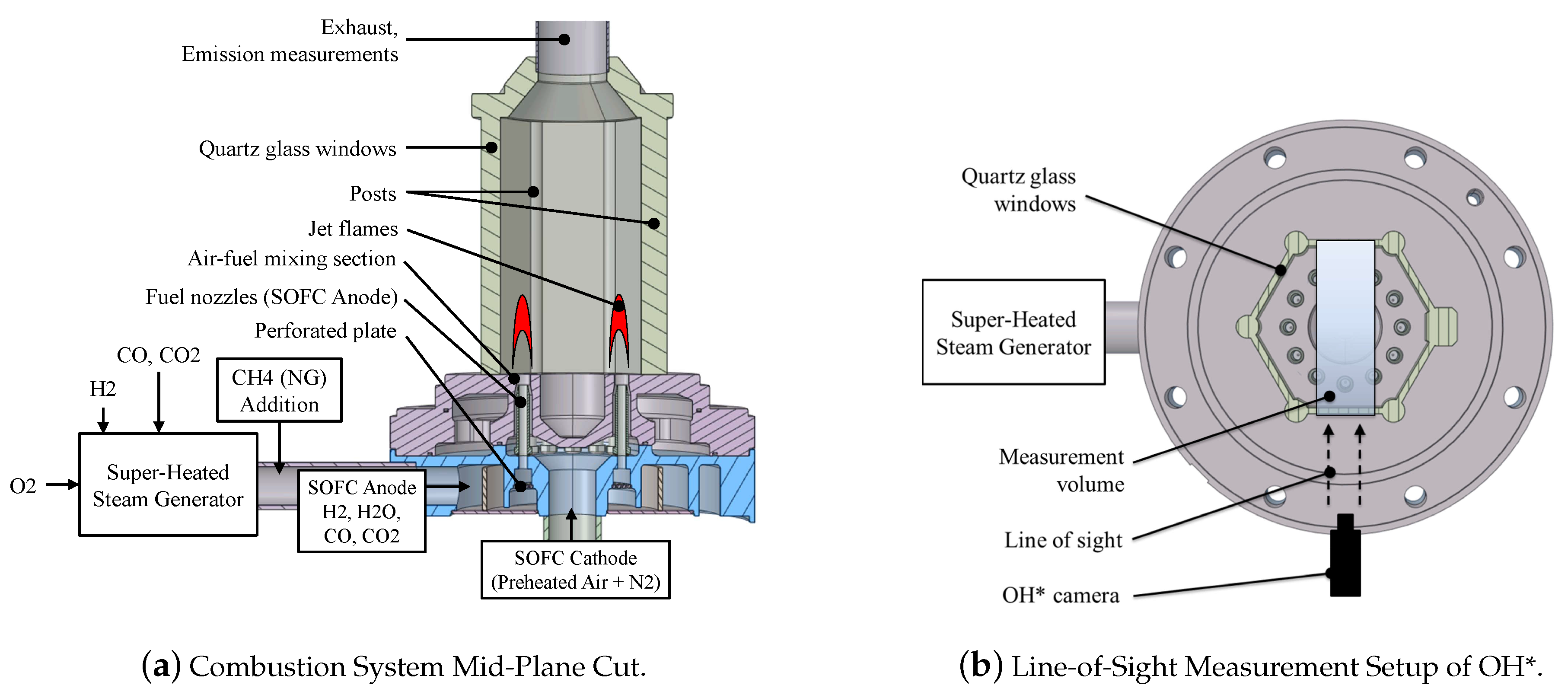
The burner system, namely F20OG.1, is shown in
Figure 1. “F” denotes FLOX similar design, the number 20 relates to the order of magnitude of thermal load and “OG” indicates operation with SOFC Off Gas. The last number simply labels the development version of the burner system.
In the context of this work, atmospheric tests are the choice of analysis, since they provide optical access at low running costs and therefore allow for a thorough analysis of the system. As stated earlier, the solid oxide fuel cell is imitated by an auxiliary upstream H2/O2 burner. It is operated in a way that it mimics anode gas compositions and temperatures as would be present with a real fuel cell in the power plant rig.
Besides the delivery of H
2O content on the anode side, CO and CO
2 are injected downstream of the super-heated steam generator. Additionally, in certain part load conditions, natural gas is introduced after the auxiliary burner to ensure reliable and stable combustion. Fuel heating values are particularly low in part load mode. The resulting gas stream from the auxiliary system is the combustor input from the anode side, as indicated in
Figure 1a. It is led to the optically accessible chamber via twelve nozzles in circumferential alignment. In a standard atmospheric test rig, this would be labeled the fuel stream.
The cathode side consists of oxygen-depleted but preheated air. This is achieved by N
2 addition to air under atmopsheric conditions. The cathode flow stream is led to combustion via an upstream plenum to a co-flow alignment around the fuel jets. As stated previously, this leads to a partially premixed combustion regime due to a short mixing section, labeled Air-fuel mixing section in
Figure 1a. Consequently, lifted-off reaction zones are present in the combustion chamber over each axially aligned nozzle.
In the present study, the burner system is characterized via certain reference conditions. Their choice is based on exhaust gas emissions measurements with carbon-monoxide as the main criterion. Measurement of NOx in the off-gas poses major challenges with prevailing high water contents after combustion. However, measurement attempts indicated that NOx emissions are in the single digit order of magnitude, referring to parts per million at dry conditions. At off-gas combustion conditions, low adiabatic flame temperatures are present, so that thermal NOx plays a subordinate rule. A measurement device is installed in the center of the downstream exhaust duct following the combustion chamber. It records averaged CO emissions in a discrete point.
Optical measurements characterizing the flame locations and spatial extensions are based on OH
* chemiluminescence. Averaged radical OH
* emission profiles are then used for validation of numerical results. Details and specifications on the measurement techniques can be found in the literature [
46,
47].
OH
* chemiluminescence is a line-of sight measurement technique. In the current combustor it is set up in a way that it covers the range of a rectangular corresponding with the size of one of the quartz-glass windows. Measurement setup alignment is displayed in
Figure 1. Since it is a line-of-sight method, OH
* signals are recorded and averaged over three front flames and three corresponding rear flames that are in-line with the front flames due to the annular alignment of the jet flames. Therefore, the OH
* results shown here display six flames in total, where the two flames are in line of sight, respectively. The numerical studies are evaluated accordingly.
2.2. Reference Operating Conditions
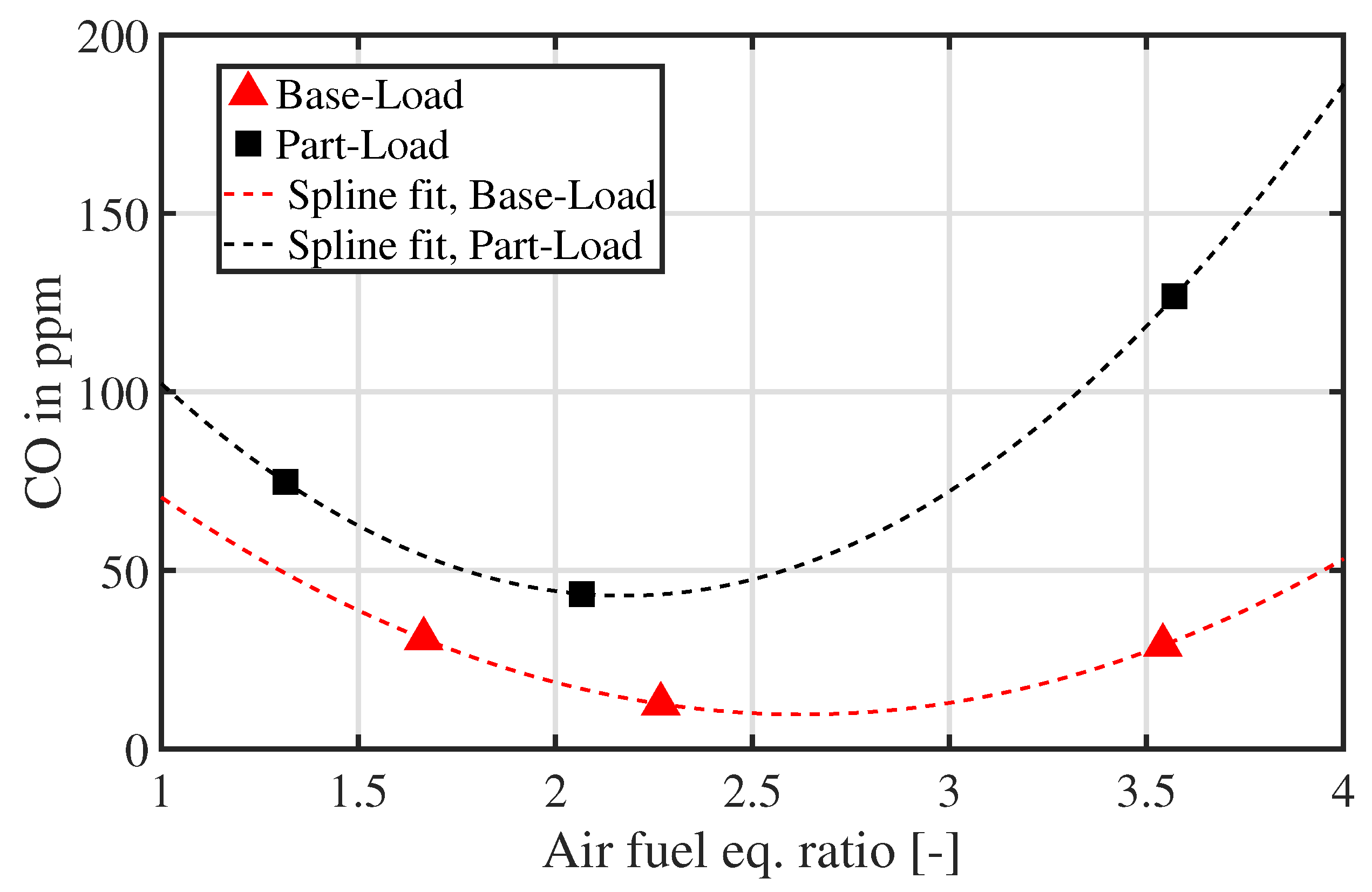
The combustion system has to be capable of undergoing a large range of operation in the context of the power plant setup. Therefore, striking operation conditions have to be picked for further analysis, in order to cover the full characteristics of the system. This is done by means of CO exhaust gas emissions measurements. The choice of investigated operation conditions is emphasized in
Figure 2, where emissions are displayed over the air fuel equivalence ratio.
According to
Figure 2, the respective base-load and part-load points are labeled as “lean”, “optimum” and “rich” with respect to their global air fuel ratio
.
denotes global equivalence ratio. The reference case is defined at near-optimum conditions w.r.t. CO emissions. The burner is operated with SOFC off-gas and therefore at extremely low calorific conditions. The reference case thermal load is about
kW. Adiabatic flame temperatures of the base-load cases are in the range of 1500 K to 1650 K. Due to the upstream SOFC, pre-heating temperatures are of the order of magnitude of 1000 K. Therefore, combustion itself realizes temperature deltas in the order of magnitude of
K.
The fuel consists of H2, H2O, CO2 and CO. The oxidizer is nitrogen-diluted air, with mass fractions and . In this application, the oxidizer is oxygen-depleted air, as would be present for the cathode-side of the fuel cell output. The categories base-load and part-load refer to power plant operation at full rotational shaft-speed and 70% fraction, respectively. The rotational shaft speed of the system operation is limited to 240 krpm at base- or full-load.
For this particular case of operation with SOFC off-gas, the inlet conditions are rather complex, therefore an overview on operation conditions for the respective cases is given in
Table 1. Estimated temperature deltas due to combustion are evaluated from Cantera simulations and reflect the low energy content of the off-gas fuel. Since part-load cases are close to lean blow-off, a small amount of methane is added to the fuel after the super heated steam generator in part-load mode for combustion stabilization.
2.3. Numerical Modeling
Numerical simulations are carried out with two major objectives. Foremost, experimental data is limited to exhaust gas emissions and flame location by OH* chemiluminescence analysis. Therefore, numerical results are validated against experimentally obtained flame position. By capturing flame position and extension accurately, numerical flow field results complement experimental findings.
Additionally, heat-loss mechanisms play a major role in low-calorific combustion and therefore, this aspect is carefully addressed in the numerical modeling and validated with experiments by means of local temperature measurements. Especially for the later transition to machine testing, it is crucial to narrow down heat-loss effects. Obviously, atmospheric test rigs will show much larger heat loss compared to isolated gas turbines, but information from numerical modeling gives also insight into phenomena upstream to the actual combustion chamber. This makes machine-integrated design much more reliable and helps with gathering experience upfront.
Numerical simulations are conducted with Ansys Fluent, version 19.1. The incompressible, steady state Navier-Stokes equations are solved with an additional energy equation based on specific enthalpy and a species transport equation.
2.3.1. Modeling Theory
In the numerical simulations, the incompressible averaged Navier-Stokes equations for reacting flow are solved with the segregated SIMPLE solution strategy for pressure-velocity coupling. The energy equation solved in the gas phase reads
Vectors are bold and tensor notation is given as bold and over-lined. The energy in Equation (
1) is in turn given as
. There, the sensible enthalpy
h is the sum over all the species of products
with the species mass fractions
.
p and
denote pressure and density, respectively.
is the effective thermal conductivity, consisting of a laminar and a turbulent fraction.
are the diffusion coefficients of species
i. The heat sources
stand for energy entries due to chemical reactions and are subject to combustion modeling. The sensible enthalpies of species
i are computed as the interval integral of heat capacity
over temperature, via
On the contrary, for solid regions (quartz glass and metal structures), the energy transport equation is the only transport equation solved and has the form
Note that Equation (
3) is solved without source terms, since radiation is not modeled in the investigated case, due to relatively low peak temperatures in the combustor. Results of the numerical analyses will be analyzed with regard to this assumption.
Therefore, convective and conductive heat transfer is assumed to be the most dominant heat loss mechanism. In Equation (
3), the sensible enthalpy is accordingly evaluated from Equation (
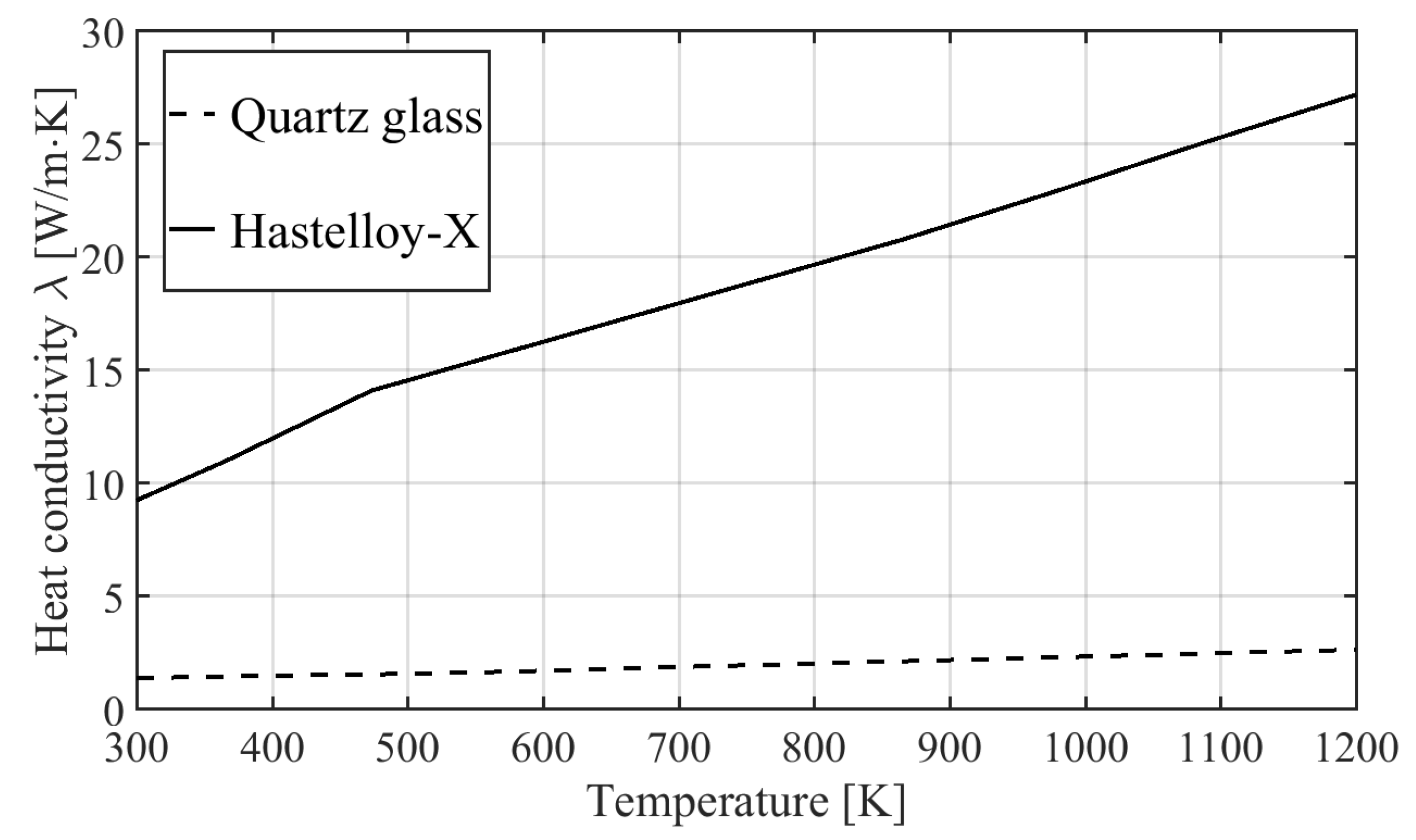
2). Thus, heat capacities and thermal conductivities of the specific solid materials are modeled with piecewise-linear relations, as exemplarily shown in
Figure 3 for the thermal conductivity.
Essential for the correct depiction of heat transfer mechanisms due to conduction and convection is the grid resolution at combustor walls. Since also a based turbulence model is used, the first cell in wall-normal direction is chosen according to .
In terms of thermal boundary conditions, several variants are used in the presented study. Adiabatic boundaries are not considered. They are the simplest, but do not account for any local temperature gradients and heat transfer mechanisms. In the presented study, the heat transfer is modeled threefold, by applying
Temperature boundary conditions (isothermal),
Heat flux boundary conditions
Conduction of fully coupled simulations.
The governing energy equation at the interface of fluids and solids without consideration of radiation generally is , which means . and are the respective conjugate heat transfer coefficients on the fluid “f” and exterior flow “ext” side.
For isothermal boundary conditions,
is prescribed,
For the general heat flux boundary conditions, convection is considered, therefore
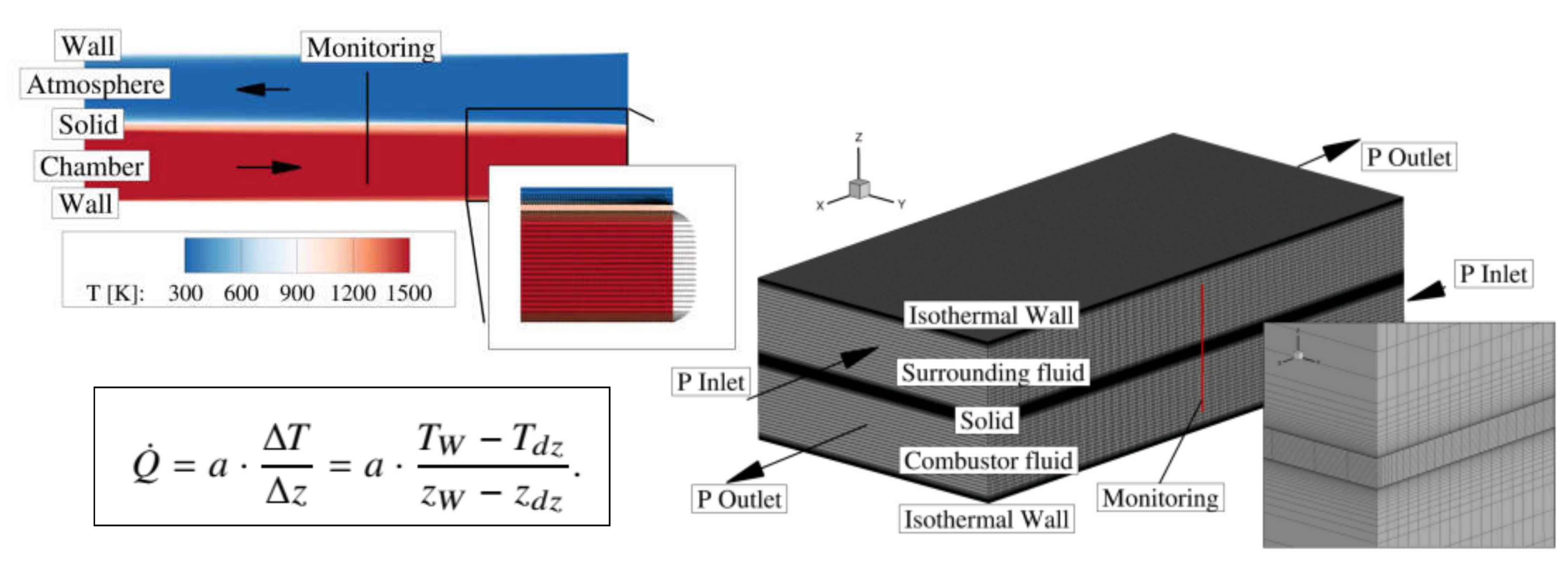
is specified, which has to be assumed a priori. Either knowledge about heat flux exists, or it has to be estimated. For this work, it was estimated by a coupled test-case with forced convection, as shown in
Figure 4.
Heat transfer coefficients are extracted from this setup by assuming thermodynamic conditions inside the combustion chamber and in the ambient, while the combustor wall is explicitly modeled. Detailed results on this investigation can be found in [
48].
For a global balancing, in fully coupled simulations, the heat flux from fluid to solid and vice versa is evaluated with
with the respective thermal conductivity
k and the wall normal distance
. The subscript
means fluid or solid. For fully coupled simulations, temperature gradients in the solid walls develop and therefore the formula in Equation (
5) has to be expanded. Depending on which side (combustor- or ambient-oriented medium) the heat flux is evaluated, the internal
or external
wall temperature has to be taken into consideration.
2.3.2. Numerical CFD Setup
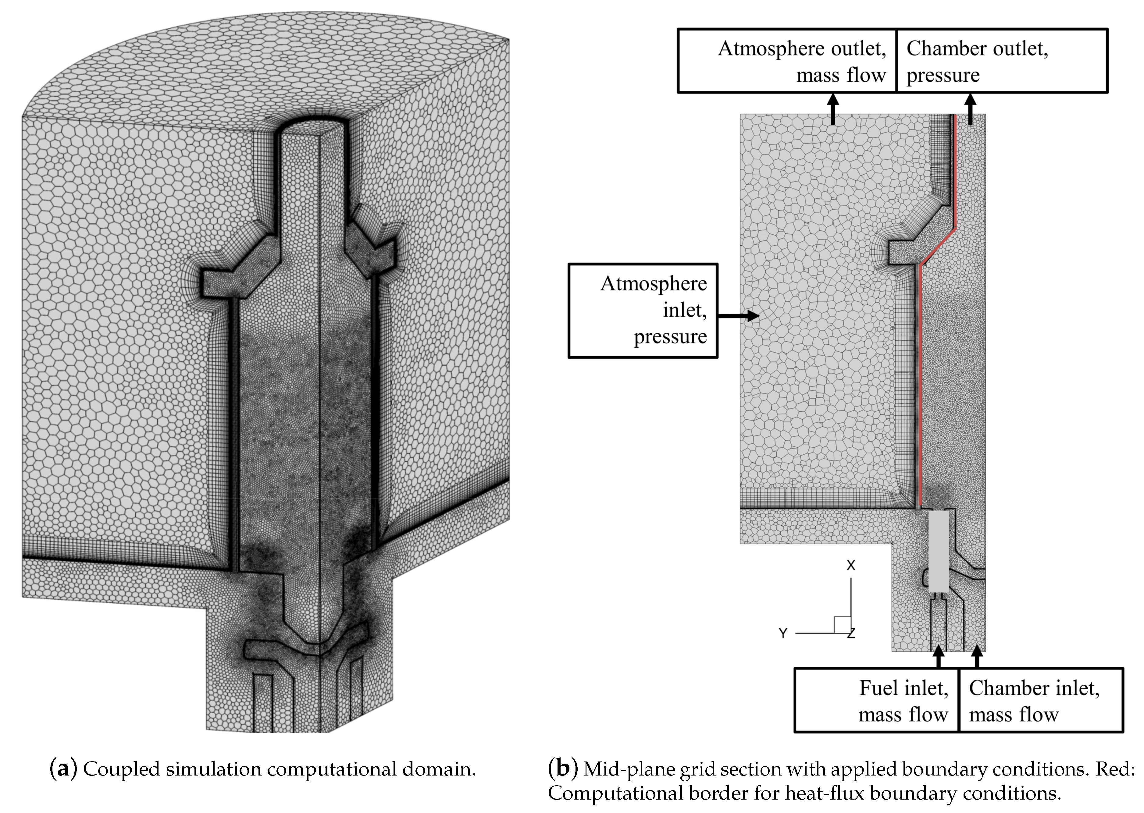
The overall computational domain is shown in
Figure 5. A segment of 120 degrees is directly modeled, in order to exploit symmetry for computational efficiency. At the same time, 120 degrees mean the inclusion of four nozzles and therefore the accountance for nozzle-nozzle interaction. Periodic boundaries are applied in the rotational direction. Fully coupled CHT simulations are carried out with the domain in
Figure 5a, whereas the isothermal and heat-flux modeling is carried out on the combustor domain only, where outer extensions are marked with the red line in
Figure 5b. The grid consists of 4.4 million cells and 9.5 million nodes. Polyhedral elements are used, which provide a good quality resolution and representation of flow field and combustion, compared to conventional tetrahedral discretization due to a larger number of interpolation points. Wall resolution of
is achieved with prism layer cells. The grid is refined in the reaction zone regions and in particular in the anode-cathode mixing zone, following the fuel nozzles. Model assumptions as presented were tested on a simplified setup, regarding grid resolution and influence of periodic boundary setting but are not explicitly shown for conciseness.
In the solid regions of posts and glass walls, the grid is structured and composed of mainly hexahedral cells. Solid cells are in total 3.778 million elements with 0.82 million nodes. For simplicity reasons, only two different solid materials are applied. Those are quartz-glass for the combustion chamber windows and hastelloy-x steel for the posts, the combustor, the combustor stand and the exhaust duct.
Numerical simulations are carried out with Ansys Fluent, version 19.1. Turbulence is modeled with a
SST approach [
50]. Pressure-velocity coupling is covered with the SIMPLE solution strategy. Spatial discretization of transport and conservation equations is the second order upwind. At first, cold flow solutions are established. Combustion is then initialized with a global EDM (Eddy Dissipation Model) approach, based on a simple reaction equation for hydrogen. Finally, combustion is depicted using the Eddy Dissipation Concept (EDC) from Magnussen [
51] and a detailed mechanism for synthetic gas combustion from Li et al. [
52]. Judging from previous jet-and-recirculation stabilized burner simulations, this combination of chemical reaction modeling is best suited. Detailed combustion modeling is necessary in order to be able to depict the complex chemistry of lifted-off jet flames. Applied flow boundary conditions are sketched in
Figure 5b.
In the case of heat-flux and isothermal modeling, constant values are prescribed for characteristic zones, namely the upstream burner section, the combustor front plate, combustor walls and the exhaust duct. For the isothermal case, an estimated temperature of K is defined for the combustion chamber walls.
Air and fuel mass flow rates are defined at the inlets according to experimentally used flow rate values, whereas the chamber outlet is modeled as a pressure outlet condition, where the gauge static pressure is set to zero. On the contrary, for the air surrounding the combustor (atmosphere), at the inlet, static pressure is prescribed, whereas the outlet is forced with mass flow (velocity), leaving the computational domain. In this way, an exhaust fan is imitated, as is present in the actual rig. The external flow conditions are estimated with simple flow-meter measurements and numerical boundaries are set in order to mimic those conditions. The combination of mass flow and pressure boundary conditions prove to be superior over pressure boundary conditions only.
All the simulations were carried out on an Intel® Xeon E5-2695v2 architecture. The coupled cases were conducted on 6*24 cores, whereas isothermal and heat-flux computations were run with 5*24 cores. Overall turnaround times amount to 18.2 k CPU-h for the coupled cases and 11 k and 9.8 k CPU-h for the heat-flux and isothermal simulations, respectively. Therefore, the overall turnaround times are still very low compared to scale resolving approaches like LES (Large Eddy Simulation) or SAS (Scale Adaptive Simulation).
3. Results
3.1. Results-Reference Case
At first, numerical and experimental findings of the reference case are presented. The reference case is defined as full-load at near optimum conditions from
Figure 2. Numerical results for different heat-loss modeling approaches are compared with experimental findings and then the flow field and temperature characteristics are discussed. The reference case data serves furthermore as a basis for evaluation of convective and conductive heat-loss in this investigation.
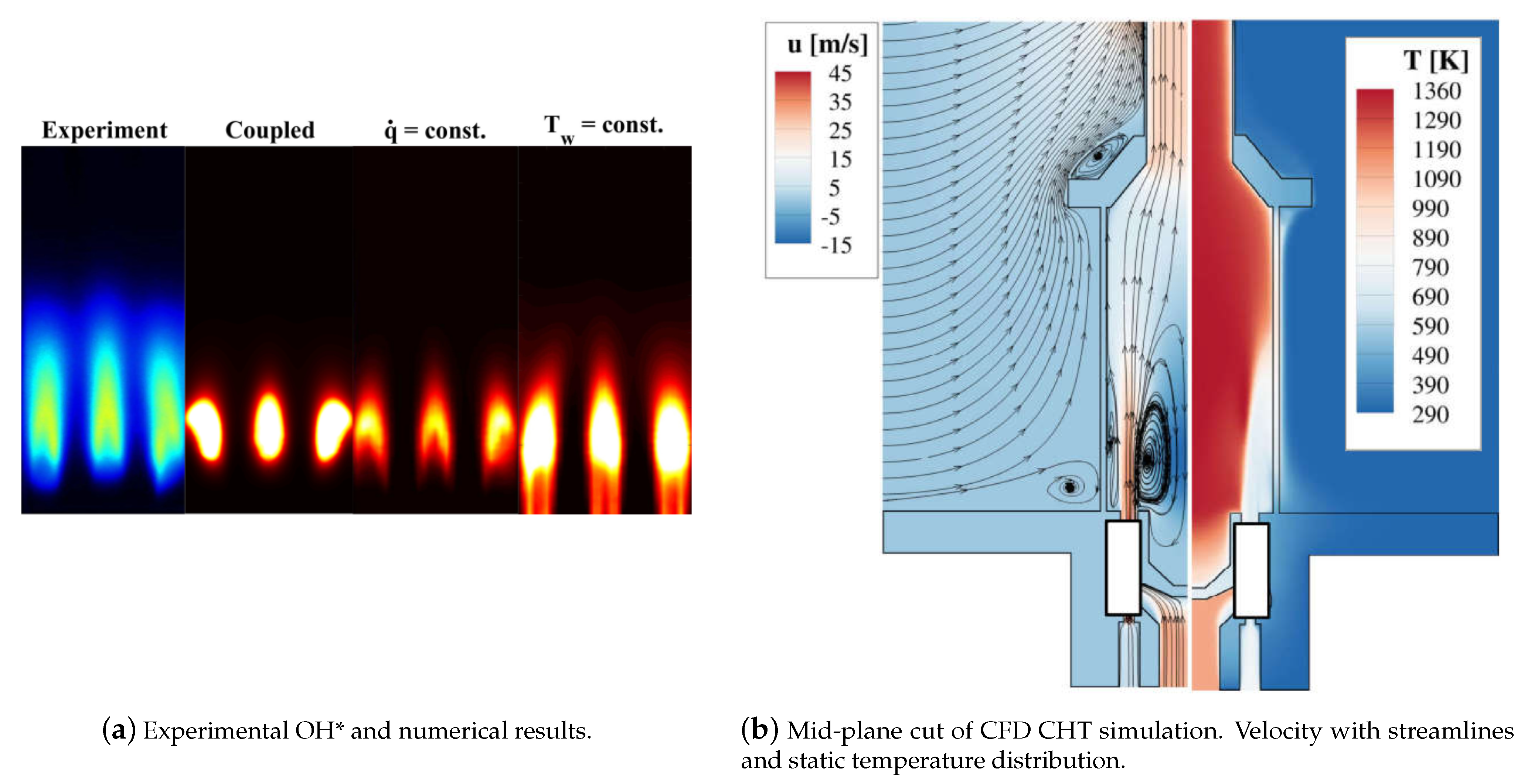
Reference case results are shown in
Figure 6. Note that averaged OH
* can be evaluated only qualitatively. The measurement results are usually scaled within one order of magnitude in intensity and there is a certain high level cut-off. In the numerical simulations, absolute values of O and H concentrations are taken into consideration and the results are consistently scaled between the three modeling approaches for heat-loss.
Experiments in the reference case (
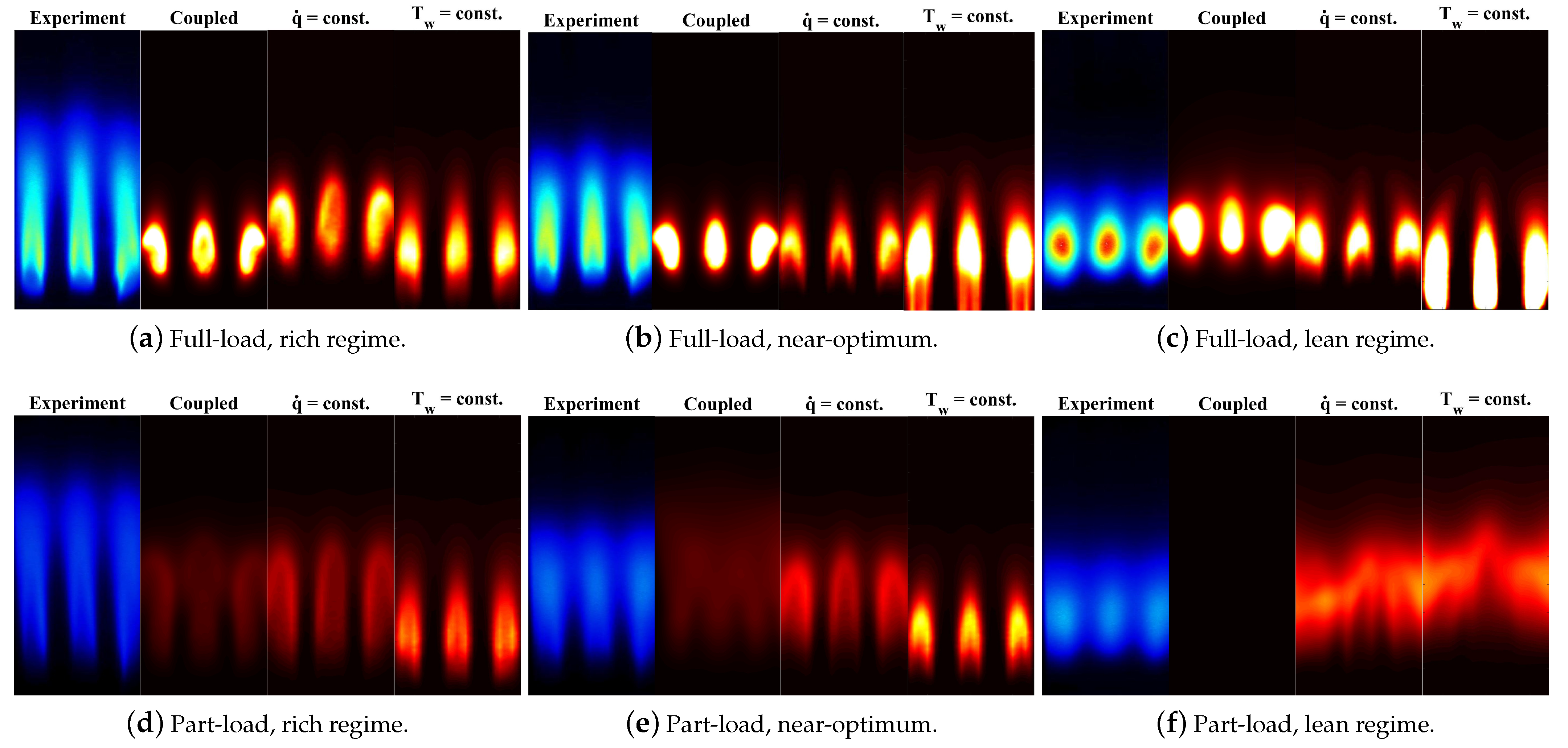
Figure 6a), and, as will be shown later, in all the investigated cases, show compact, discrete flames with a certain lift-off from the nozzles but still a limited elongation in the downstream direction. This is important for later gas turbine integration, since in this way there is no interaction to be encountered with downstream mixing air and therefore no increased CO emissions are expected. Another characteristics of the reaction zones is an inverse u-shape distribution of the single flames. Judging from the averaged images, it is assumed that the reaction zones are distributed regularly in circumferential direction for different nozzles.
Numerical simulation approaches reproduce flame lift-off nicely, except the isothermal case. This is probably due to poor estimation of upstream wall temperatures that heat the upstream flow and foster reactivity. The best reproduction of experiments is achieved by the heat-flux modeling approach, where also the u-shape flame characteristics is reproduced. However, in all the cases, reaction zones are significantly short in axial direction. This is due to mixing deficiencies of the RANS approaches and probably the employment of simplified chemical reaction schemes.
Since comparison in terms of flame anchoring and position seems to be sufficient for the reference case, numerical results for velocity and temperature distribution are further analyzed in
Figure 6b. The combustor averaged flow field shows the distinct characteristics of a jet-and-recirculation stabilized burner. Axial jets with high momentum issuing into the combustion chamber cause development of a large inner recirculation zone that helps with combustion stability by hot gas retransport to the flame root. As a consequence, remarkably homogeneous temperature distributions are achieved in the chamber, leading to the lower peak temperatures with NO
x levels to be expected to be in the order of single digit values in parts per million. NO
x could not be measured due to very large water contents in the combustor off-gas.
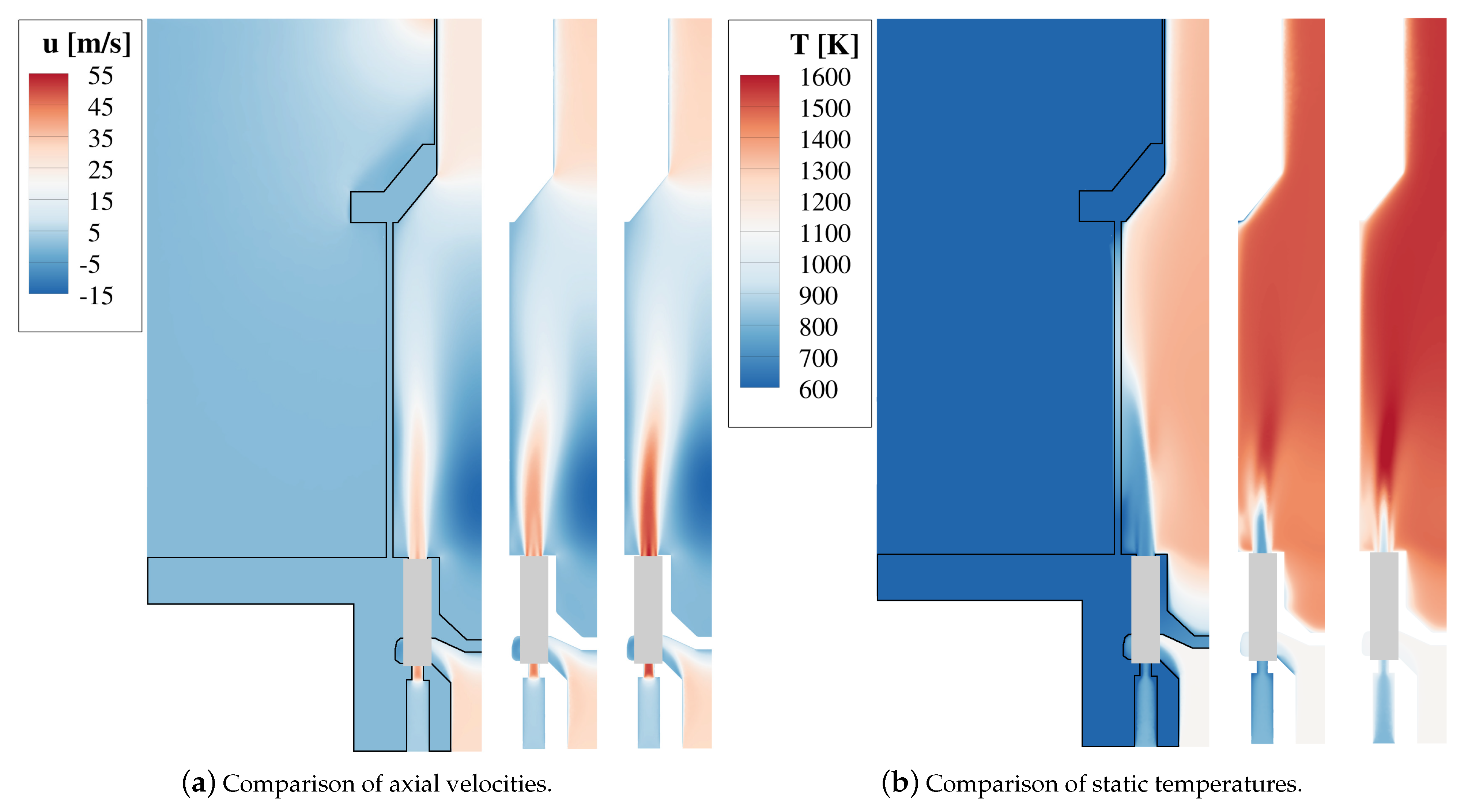
The mid-plane results for different simulation approaches are shown in
Figure 7. In this context it becomes evident that different ways of treating the heat-loss mechanisms can have significant impact on flow field and temperatures.
Jet axial velocities are the lowest for the coupled case, whereas they increase for the heat-flux modeling and are the highest for isothermal walls. This circumstance is closely related to temperature distributions, since they affect the local density. In the coupled case, heat discharge is the greatest, therefore lower temperatures in the combustor develop and, as a consequence, lower velocities are present. At the same time, when jet velocities are higher, the formation and magnitude of the inner recirculation zone becomes more prominent, leading to an increased re-transport of hot gases to the reaction zones and therefore stabilizes and enhances combustion. In the balanced, averaged scenario of reacting steady state RANS simulations, the two effects are superimposed but can not be separated. However, this leads to the distinct differences in velocity magnitudes and peak temperatures between the single modeling strategies [
49].
Another reason contributing to the highest velocities in the isothermal case is that, due to the zonal prescription of temperature values, the fuel is slightly heated upstream, as can be seen on the bottom of the right picture in
Figure 7. This heat entry into the system leads to lower fuel densities and therefore enhanced axial velocities. This denotes one downside of isothermal modeling, since the temperature profiles would have to be particularly refined and elaborated, if one would want to depict correct heat loss in the whole computational domain, requiring a large amount of modeling effort.
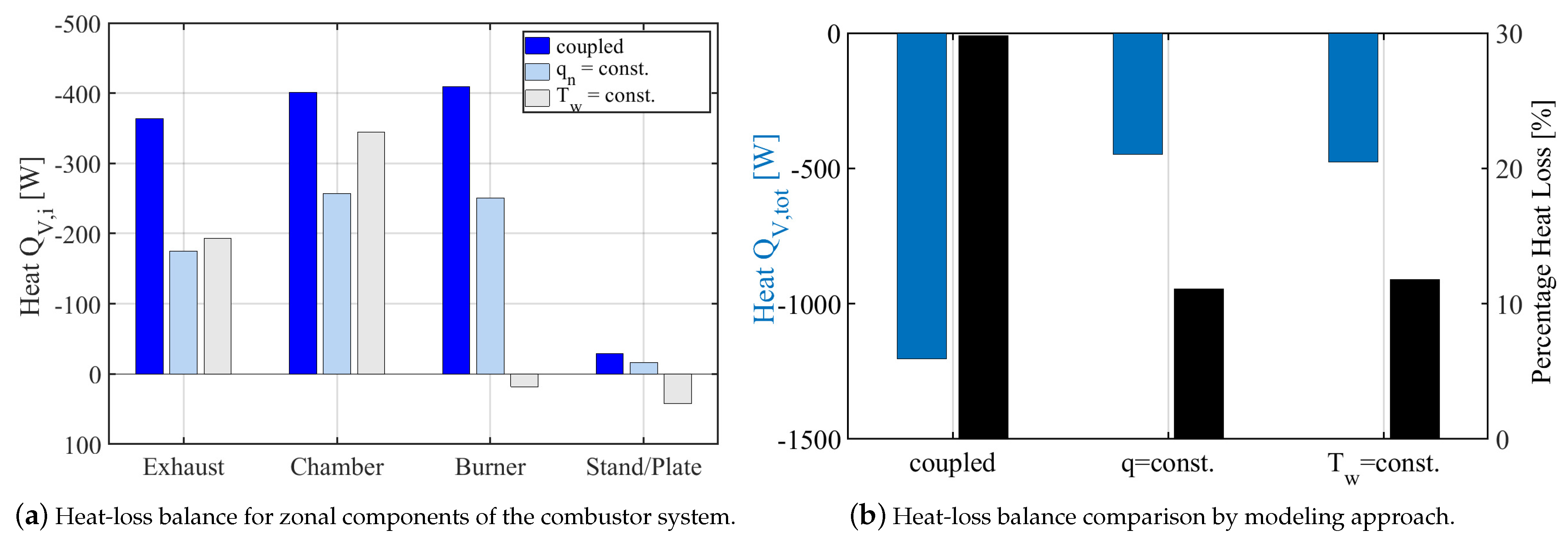
The main reason for the modeling endeavor with three variants for the heat losses is to achieve a high quality assessment of heat loss in the atmospheric burner tests. This is studied for the reference case in
Figure 8. Componentwise discharged heat is shown in
Figure 8a, whereas the total heat loss is balanced in
Figure 8b. It becomes obvious from
Figure 8a that most heat is discharged in the coupled case, while isothermal and heat-flux modeling are comparable. Confirmation of the situation with unwanted upstream flow heating from
Figure 6a is given by burner and combustor stand results in the isothermal case, where heat is even induced due to defined wall temperatures. Upstream temperatures are generally hard to estimate due to complex test stand construction and strongly depends on the outer extension choice of the computational domain. A solution would be to further distinguish local regions for the scalar temperature definition, which comes however with significantly increased modeling effort prior to simulation.
The total balance in
Figure 8b confirms the observation that discharged heat is probably overpredicted in the fully coupled CHT case, whereas heat-flux and isothermal case are in the same range. The most remarkable aspect is that the overall heat loss with respect to total thermal power amounts to 15–20%. Therefore, careful insulation assessment in the experiment is crucial, not only in atmospheric tests but also for later machine configuration. This is especially important in the investigated case of low calorific combustion, where slightly increased heat loss can make a big difference for combustion stability.
3.2. Results-Case Study
A bigger picture of combustion characteristics of the F20OG.1 is given by studying all the cases as defined in
Figure 2. This is carried out in
Figure 9. As mentioned earlier, all investigated points show discrete and compact flames, as is highly desirable for machine integration of the combustion system. Reaction zone elongation is the longest and most critical in part load situations, which are however very close to lean blow-off. The measured trends in base-load show the longest flames with lowest intensities in the rich regime, which is counter-intuitive. However, one has to consider that air temperatures are at high levels, as can be seen in
Table 1. Especially in the lean case this leads, in relation to the lower fuel mass flow, to larger impulse ratios between air and fuel stream and therefore enhances mixing. Additionally, the anode side that is considered as fuel is exhaust gas from the super heated steam generator. Therefore, naturally, the fuel has significant fractions of inert content (H
2O, CO
2), so rich cases can be relatively non-reactive compared to the lean mixture, leading to elongated reaction zones and lower radicals emission levels.
Numerical simulations generally deliver a good reproduction of experimental findings. Especially the fully coupled CHT and the heat-flux modeling approach deliver sensible results in terms of qualitative lift-off height and reaction zone extensions. Major deviations are observed for the isothermal cases, which are linked to lack of detail in upstream prescription of temperatures and therefore enhanced reactivity of the mixture. Previously, it was discussed that in the coupled case the largest amount of heat is extracted from the combustion system. Judging from the part-load results, especially in the lean regime, where the CHT simulation shows no reaction, indicates that the heat-loss is overestimated in the coupled CHT case. This could be linked to overprediction of forced convective heat transfer due to uncertainties in the modeling of atmospheric flow. The outer flow situation is hard to determine due to very low velocities that are driven by an exhaust fan.
Measured emissions are listed in
Table 2. The CO values are low for the base-load cases but distinctly higher in part-load, due to more unsteadiness in the vicinity of lean blow-off. Values for NO
x emissions are given where possible. However, they are prone to large insecurities due to the high water content in the exhaust gas, as can also be seen in
Table 2. Indications are that NO
x are in the single digit order of magnitude w.r.t. parts per million.
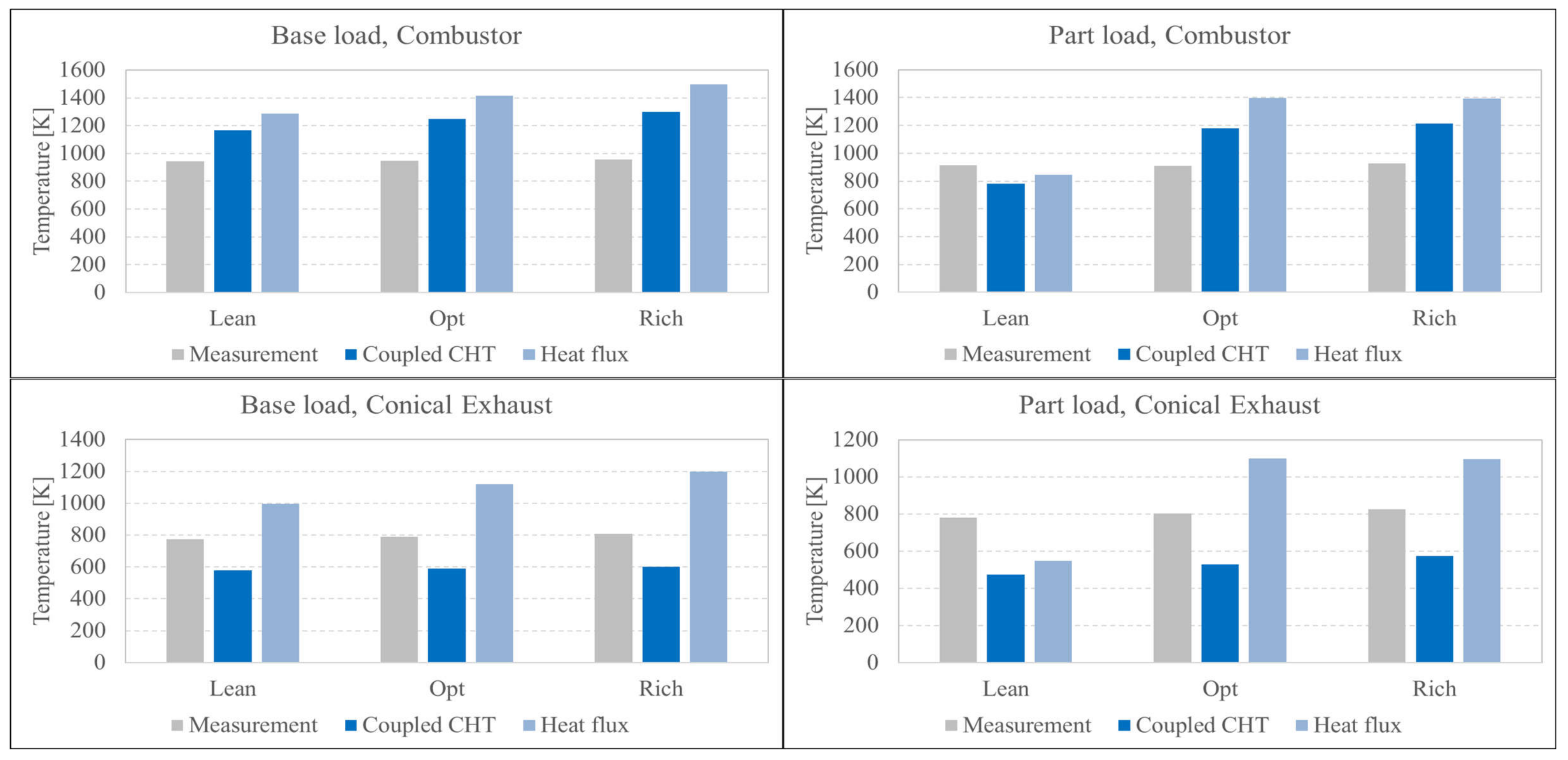
As round off analysis, pointwise temperature measurements are shown in
Figure 10. Temperatures are evaluated for the coupled CHT and heat-flux modeling of heat loss and balanced with experimental findings.
In general, in the combustion chamber near-wall regions simulations overpredict the measured findings, but are within the same order of magnitude. The coupled simulation performs better in terms of absolute temperature values, especially in the downstream conical section but consistently for all operation points.
A possible reason for deviations between measurements and numerical modeling are radiation effects. Especially for the cases with heat-flux boundary modeling, large deviations to measured temperatures are present. In those cases, it is difficult to quantify radiation effects, since pre-simulation efforts like the extraction of heat transfer coefficients as shown in
Figure 4 will not be able to quantify radiation heat-loss, since it does not fully depict gas radiation of the whole combustion chamber molecules. Therefore, it is concluded that radiation should not be neglected, even in the case of low-calorific combustion, unless a deviation in temperature in the order of magnitude 10–20% is acceptible in the design process. From our experience, this order of magnitude of radiation heat-loss does contribute to flame stabilization, but does not fundamentally change reaction zone location and spatial extensions.
Another aspect adding possibly up to temperature differences between experiment and simulation are measurement uncertainties of the thermo-couples, which are however hard to quantify.
With regard to the modeling values being in the same range as measured values, it can be stated that the modeling approach, especially the RANS based fully coupled scheme, finds absolute temperature levels in the right order of magnitude with a certain level of overprediction. The approach can therefore be used for the machine integration design as the worst case estimation for thermal load of the combustor structure in a gas turbine, when combustor temperature regimes are viewed.
4. Conclusions
A novel combustor based on jet-and-recirculation stabilized combustion, formerly known as FLOX® was investigated by means of optical measurements, exhaust gas analysis and numerical CFD simulations. The combustion system operates in the context of a hybrid power plant, processing off-gas from an upstream fuel cell. This leads to the main peculiarity of the burner system that it has to be able to process low-calorific fuel. It was however shown in previous works that the combustor is also able to run with conventional natural gas.
It was demonstrated that the burner system is able to cover a large operational range in the lean regime with indication of the low NOx emissions in the single digit order of magnitude, despite low fuel energy contents. Lean blow-off was reached with off-gas around an air fuel ratio of 3.6. The burner features discrete and compact flames, as was demonstrated by means of OH* chemiluminescence measurements.
Numerical simulations were conducted and compared with measured data and the CFD conveniently complemented measurement data with information on flow field and temperature distribution. It is possible to support measurements with low-fidelity CFD, if careful treatment of boundary conditions is provided and detailed chemistry is used.
Different modeling strategies for the heat-loss were taken into consideration, in order to quantify heat-loss effects in the system reliably, which is of special relevance in low calorific combustion. It was shown that for this burner configuration, the heat loss is within range of 20–30% of overall thermal power.
Findings of the investigations carried out are of particular relevance for integration of the combustion system into the actual power plant. Although the combustor in the plant will have the lower heat-loss, the studies conducted raise awareness for critical thermal design and it was shown that it is feasible to use the employed CFD tools for reliable thermal design of the machine-integrated combustor. It is expected that low emission behavior of the combustion system will be reflected in machine operation.
As a major conclusion from the numerical studies, a careful assessment of thermal boundaries is crucial, especially with lower fuel energy contents. Different choices of thermal boundaries can have significant influence on flow field and combustion. Low-fidelity boundary conditions, like heat-flux and isothermal temperature prescription, have the advantage of lower modeling effort and more efficient computations, are however seen critical if no detailed a priori knowledge on heat transfer is available in the modeling process. Fully coupled CHT simulations have a high modeling effort but deliver high quality results, not necessarily in terms of reproduction of a flame position and extensions but in terms of temperature prediction, which is important in the combustor design process. In order to increase the predictive accuracy of the numerical simulations for design and construction, a major improvement would be the incorporation of radiation models.
In general, the choice of simulation method should depend on the respective target values of the design process. In case combustion systems are designed in view of flame stabilization and reaction zone extensions, it can be a sensible approach to neglect radiation effects, especially in the case of low-calorific combustion, judging from the good match between OH* measurements and numerical simulation as presented in the paper. If however temperature level prediction for further analyses, e.g., life-span estimation with FEM (Finite Element Method) is important, radiation effects should be taken into account in the numerical model, despite the much higher computational effort.
The presented burner system is able to run with high and low calorific fuels at low emissions with stable combustion and covers a large operational range. The design is therefore integrated in an actual hybrid power plant application, where one crucial point for successfull transition is the match of operational assumptions in the atmospheric tests with actual plant behavior, which will require future analysis. Apart from this, the burner system can be used in applications with higher power levels by applying common scaling rules based on geometric ratios and Mach number similarities. The presented burner system is basis for further burner development at DLR, going towards applications like biogas or hydrogen combustion in decentralized energy applications.
