Article

Design and Thermal Modeling of Modular Hybrid Excited Double-Sided Linear Flux Switching Machine

1
Department of Electrical and Computer Engineering, COMSATS University Islamabad, Abbottabad 22060, Pakistan
2
Department of Electronics Engineering, University of Engineering and Technology Peshawar, Abbottabad 22060, Pakistan
3
Open AI Lab, National Yunlin University of Science and Technology, Douliou 64002, Taiwan
4
Centre of Renewable Energy, Government Advance Technical Training Centre, Hayatabad, Peshawar 25100, Pakistan
5
Computer Sciences Program, Turabah University College, Taif University, P.O. Box 11099, Taif 21944, Saudi Arabia
*
Authors to whom correspondence should be addressed.
Energies 2021, 14(24), 8511; https://doi.org/10.3390/en14248511
Submission received: 15 November 2021 / Revised: 10 December 2021 / Accepted: 14 December 2021 / Published: 17 December 2021
(This article belongs to the Section F: Electrical Engineering)

Abstract

:
This paper presents a Hybrid Excited Double-Sided Linear Flux Switching Machine (HEDSLFSM) with a crooked tooth modular stator. Generally, the conventional stators are made of a full-length iron core, increasing manufacturing costs and iron losses. Higher iron losses result in lower efficiency and lower overall performance. A U-shaped modular stator with a crooked tooth is used to lower iron consumption and increase the machine’s efficiency. Ferrite magnets are used to replace rare earth magnets, which also reduces the machine cost. Two DC excitation windings are used above and below the ferrite magnet to reduce the PM volume. 2D electromagnetic performance analysis is done to observe the key performance indices. Geometric optimization is used to optimize the Split Ratio (S.R), DC winding slot area (DCw), and AC winding slot area (ACw). Stator Tooth Width (STW), space between the modules (S.S.), and crooked angle ( α ) are optimized through JMAG in-built Genetic Algorithm (G.A.) optimization. High thrust force density and modular stator make it a good candidate for long-stroke applications like railway transits. The thermal analysis of the machine is performed by FEA analysis and then validated by 2D LPMC (Lumped Parametric Magnetic Equivalent Circuit) model. Both analyses are compared, and an error percentage of less than 4% is achieved.

1. Introduction

The world’s population is increasing at an alarming rate; the increased population needs improved facilities and optimal use of natural resources without bringing a significant undesirable change in the atmosphere. Transportation and mobility are some of the necessities of modern-day life. Rotary machines have been widely used and employed in transportation systems like Railways and Hybrid Electric Vehicles (HEVs). However, rotary machines for linear motion require an efficient gearing system, which increases the machine’s overall cost and considerably lowers efficiency. Linear Induction Machines (LIMs) have been used recently to overcome the gearing system hurdle.
LIMs require a lower volume of secondary and thereby reduce the cross-sectional area of the tunnels and underground stations. Given all the advantages and lower manufacturing cost, LIMs have been adopted in many railway transits [1,2]. However, the significant shortcomings in LIMs are the power factor and efficiency of the machine are not satisfactory. In comparison to LIMs, Linear Flux Switching Machines (LFSMs) have higher thrust force [3], quick dynamic response system [4], bipolar flux linkage [5], and higher overload capacity [6] with low cost and robust secondary [7]. As in LFSM, all the excitation sources are placed on the short mover, leaving the secondary part completely passive, which makes it suitable for railway transits. Broadly, division of LFSM based on geometry results in two significant types (a) Single-Sided LFSM (SLFSM) (b) Double-sided LFSM (DLFSM). SLFSM provided the required thrust force in the x-axis with a high normal (attractive/repulsive) force in the y-axis [8]. The latter is undesirable, acts as parasitic/fractional force, and affects the machine bearing system [9]. To overcome the normal force problem, DLSFM is introduced, which cancels the effect of normal force and increases the resulting system’s efficiency [10]. DLFSM can be further subdivided into two major topologies: (a) dual stator with a single mover and (b) dual mover with a single stator. The dual stator can be achieved by connecting two movers back to back so that the two stators sandwich the mover, while in the case of dual mover, the stators are connected back to back in a mirror image that forms in between the two movers [11].
The excitation source is also one of the attributes on which the LFSMs are divided into three categories: (a) Permanent Magnet LFSMs (PMLFSMs), in which the main excitation source is a permanent magnet, (b) Field Excited LFSMs, in which the excitation source is Direct Current (DC), and (c) Hybrid Excited LFSMs (HELFSM), which are excited by all three sources, i.e., PM, DC, and AC. All three types have major applications such maglev transportation [12], railway transit [13], linear actuator for oil pumping, and electromagnetic lunch system [14] due to its high thrust force density and higher efficiency [15]. Prices of rare earth magnets such as neodymium and dysprosium increase day by day, and thereby its use in PMLFSM increases the manufacturing cost of the machine. To lower the cost, machines such FELFSM and HELFSM are proposed, which, like PMLFSM, have high thrust force density and higher overall efficiency without using the rare earth magnet. FELFSM only has DC excitation. It has a lower thrust force density than HELFSM, and DC excitation increases the overall copper losses of the machine, thereby decreasing the whole machine’s efficiency [16].
DSLFSM has advantages such as higher thrust force density, higher power factor, and efficiency; however, detent force is a severe drawback and introduces a high thrust ripple. Authors in [17,18,19] suggest optimization of PM length and width, skewing of the stator tooth, and replacing common stator tooth by staggered tooth, respectively, to minimize the detent force. Staggering of the stator tooth majorly decreases the detent force, but it also results in a lower thrust force density. Modular structure has been used and employed to reduce the end effect and mitigate the machine’s end effect [20]. Cao et al. [21] presents a comparative study of switched reluctance permanent magnet machine and linear flux switching machine for railway transportation. The author in [22] uses a genetic algorithm to optimize LIM considering important performance parameters. Authors in [
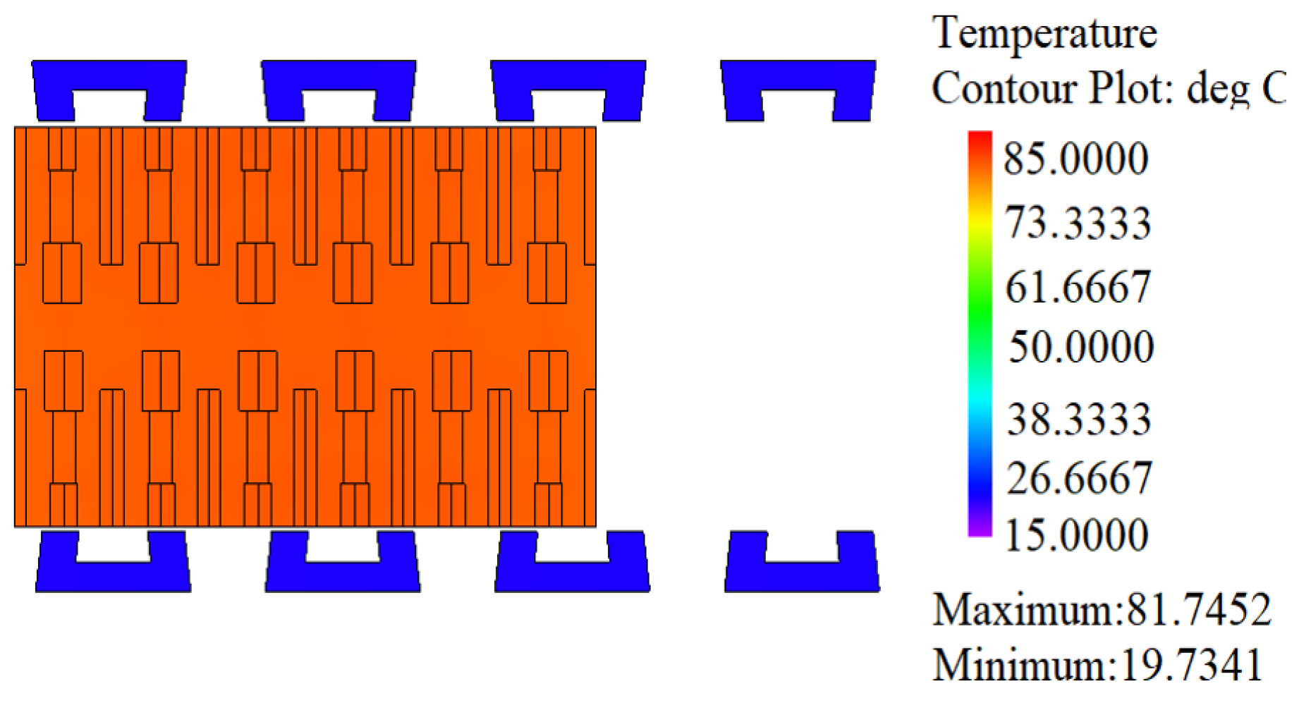
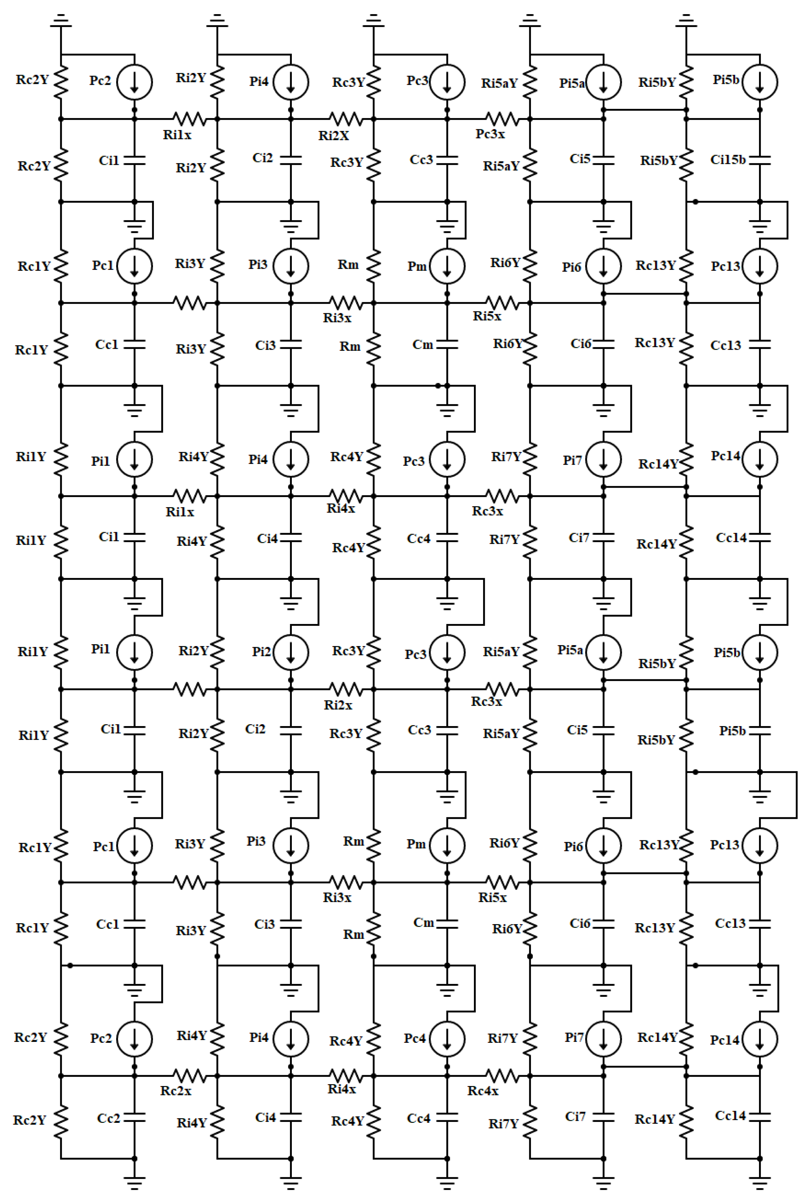
23] have analyzed temperature distribution and ignored the overall rise in temperature of the machine. Sun et al. [24] considered temperature distribution in different parts of the machine by performing 2D and 3D analysis, but this technique makes the process very time-consuming and complex. Authors in [25,26] divided the whole of the machine into different parts, and then found the temperature at every part individually, which is an efficient and robust method with reliable results.
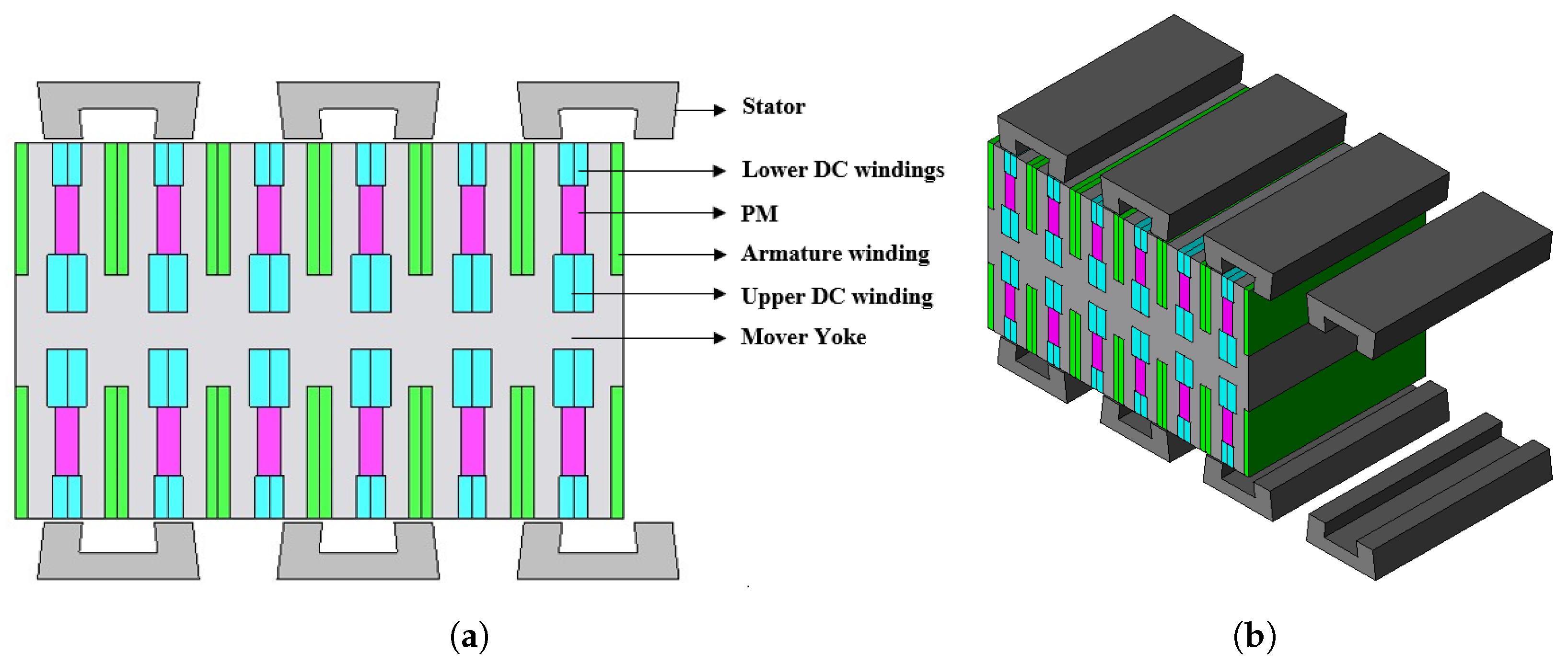
This paper presents a DSLFSM with a crooked tooth modular stator. Two DC excitation windings are placed above and below the ferrite magnet. Concentrated armature winding overlaps the PMs, thereby enhancing the overall flux linkage of the machine. Modular stator decreases iron consumption and manufacturing cost and increases overall efficiency by reducing iron losses. Ferrite magnets are employed to lower the cost of the machine. 2D FEA analysis is performed by registered JMAG version 20.1. Several key parameters are optimized by geometric optimization (GO) and genetic algorithm (GA) to increase the machine’s overall performance.
The rest of the paper is divided into eight main parts, Section 2 presents the machine topology, Section 3 presents the working principle of the machine, Section 4 shows the electromagnetic performance of the machine, Section 5 shows the influence of different parameters on the performance of the machine and optimization of those parameters. Section 6 presents efficiency analysis and thermal analysis is done in Section 7. Finally, Section 8 presents the overall summary of the paper.

2. Machine Topology

Figure 1 shows the proposed HEDSLFSM. Two DC excitation windings are used to achieve the desired thrust force density by reducing the volume of the permanent magnet ( P M V ). A ferrite magnet is used to minimize the overall cost of the machine. All the excitation sources are placed in the short mover, which reduces the manufacturing cost. A stator is in the form of a U-shaped module placed at a certain distance from one another without any magnetic or electrical contact. Using a modular stator reduces the iron consumption and lowers the iron losses; it therefore helps achieve higher efficiency. Introducing a crooked tooth increases the machine’s flux linkage, decreasing the no-load detent force and increasing the overall average thrust force. Ferrite magnets are used, having a remnant flux density (Br) of 0.4 T . The air gap between the stator and the mover is 0.8 mm, and the machine’s stack length is 90 mm. Figure 2 shows the definition of different design parameters, while Table 1 gives the machine’s detailed design parameters.

3. Working Principle

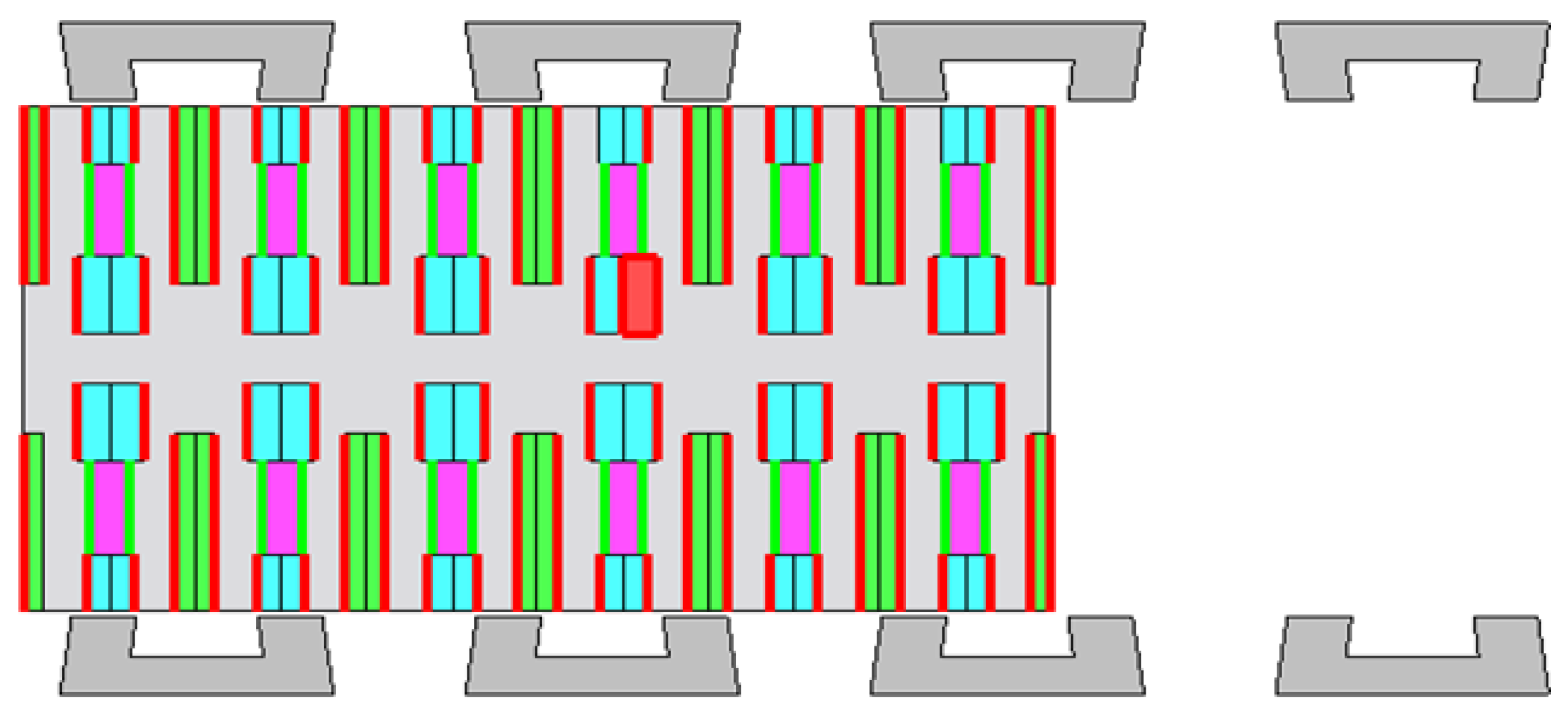
As the mover is sandwiched between the two stators and all the excitation sources are present in the mover, the flux starts at the mover. Both DC and permanent magnets are so aligned that they reinforce each other’s flux. 
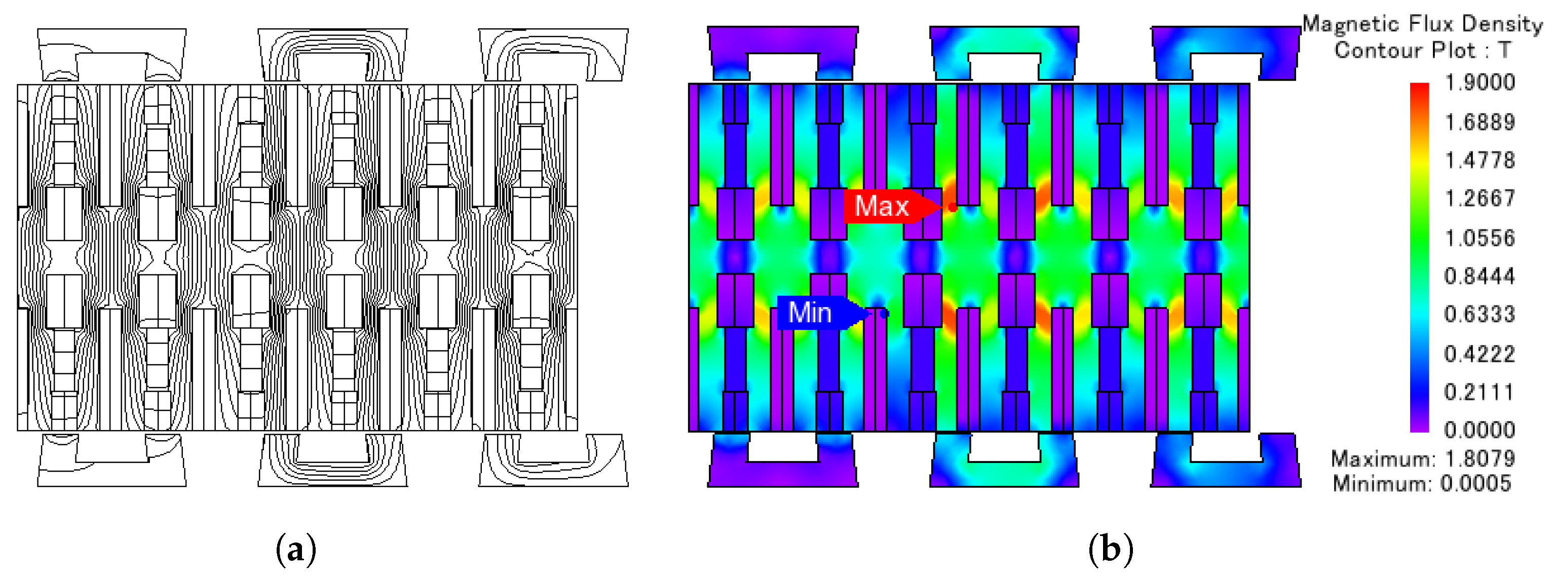
Figure 3 shows the flux linkage due to PM excitation only; it can be seen that it only circles in the yoke of the mover, and a minimal amount of it goes into the stator.
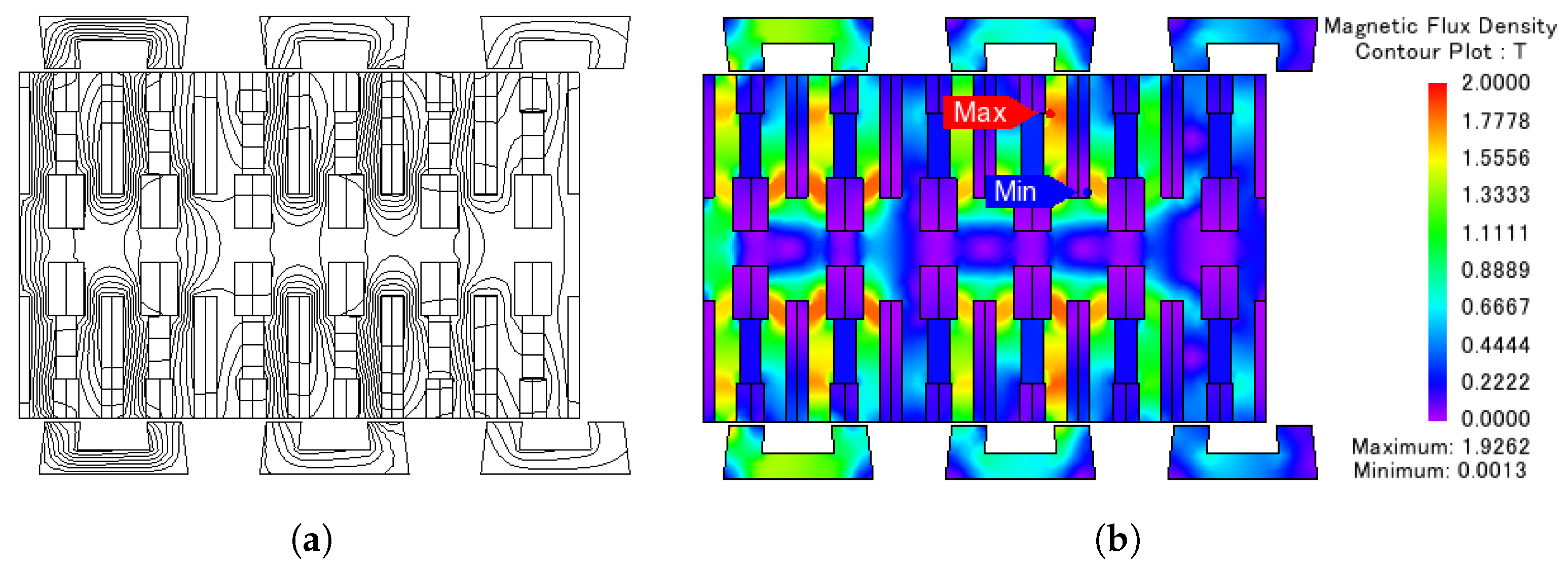
Figure 4 shows the flux linkage because of DC, and it can be seen that a considerable amount of flux passes through the machine’s stator. Figure 5 shows the combined flux linkage of both DC and PM, and it can be seen that the flux follows a path flowing through yoke through the magnet to the stator, then from the stator back to the mover pole, and then passes through the magnet into the yoke, then onto the second side of the machine. As the machine’s stator is modular, therefore, to have a sinusoidal flux linkage, the modules should be placed at a specific distance. The number of stator poles should be carefully selected using Equation (1).
S p = M s 1 ± n 2 q
where S p represents the stator pole, M s represents the mover slots, q denotes the number of phases and n is any natural number. Various values of natural numbers are considered, and the respective pole/slot combination is analyzed. It was observed from the analysis that the machine has a bipolar flux linkage and unipolar thrust force (TF) for two combinations, 5/6 and 6/7 given in Table 2. The thrust force for the 6/7 combination was lower than the 5/6 combination; therefore, it was neglected.
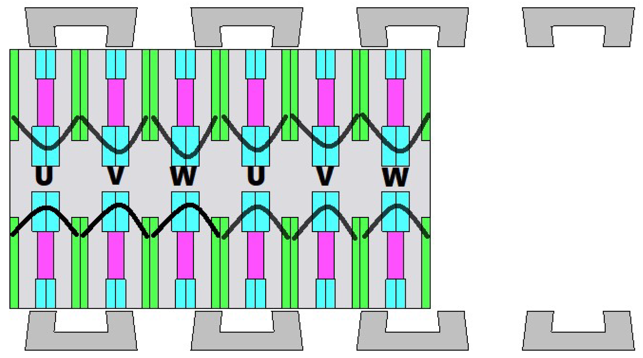
After successful selection of the pole/slot combination, the machine’s winding configuration can be selected accordingly. The type of winding to be used is dependent on the coil span of the machine, which is the axial distance between the starting and ending point of the coil and is given by Equation (2)
C s = [ f o r   d i s t r i b u t e d   w i n d i n g = m a x [ f i x [ M s T s ] ] f o r   c o n c e n t r a t e d   w i n d i n g = 1 ]
where C s represents the coil span, m a x is to return maximum, and the f i x is to return a whole number. For a three-phase balanced machine, the individual phases should be separated by Y120°. Phase offset, in this case, can be found by using Equation 3, where K is the phase offset and q is an integer value of 0 , 1 , 2 S p 2 1 .
K = M s 3 S p ( 1 + 3 q )
Different values of q are considered and analyzed, and if no suitable value for the integer is found, then the pole/slot combination is changed. In the case of the 5/6 combination, the value for K is 1, so concentrated winding is considered. Figure 6 shows the winding configuration of the machine.

4. Electromagnetic Performance Analysis

Key performance parameters like no-load flux linkage ( φ p p ) , corresponding THDs, detent force ( F d ), thrust force (TF), and normal force ( N F ) of the machine are analyzed and observed. Parameters like φ p p , F d , and N F are achieved from the 2D FEA analysis directly, while the mathematical calculation is required to find THDs and thrust force density ( T F d ). Equation (4) is used to find THDs of the machine, considering harmonic components of the flux linkage.
T H D = Σ k = 2 k φ k 2 φ 1
T F d = T F a v e r a g e V m
where φ 1 represents the flux linkage’s fundamental component and φ 2 up to φ k represents the harmonic components. 
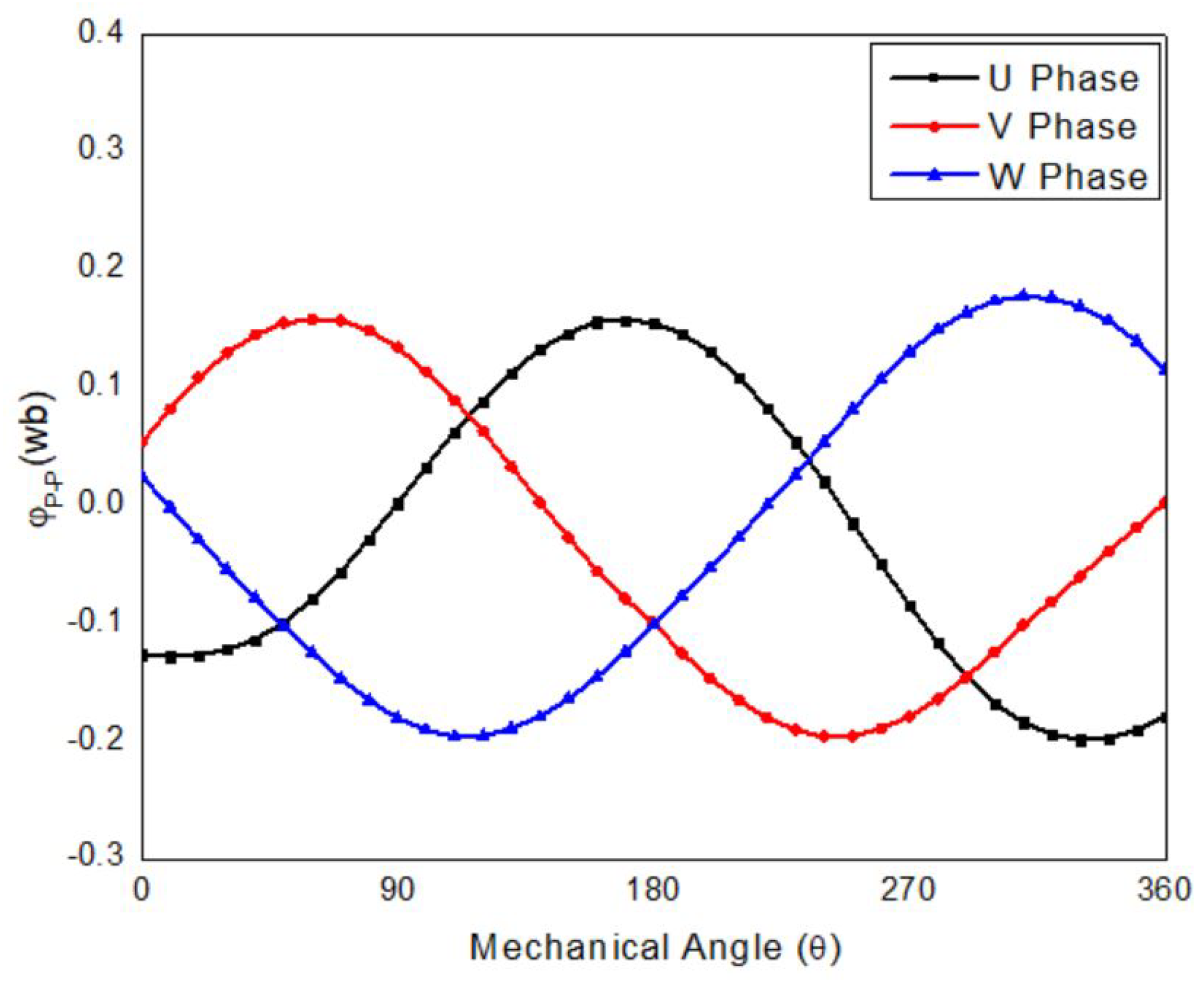
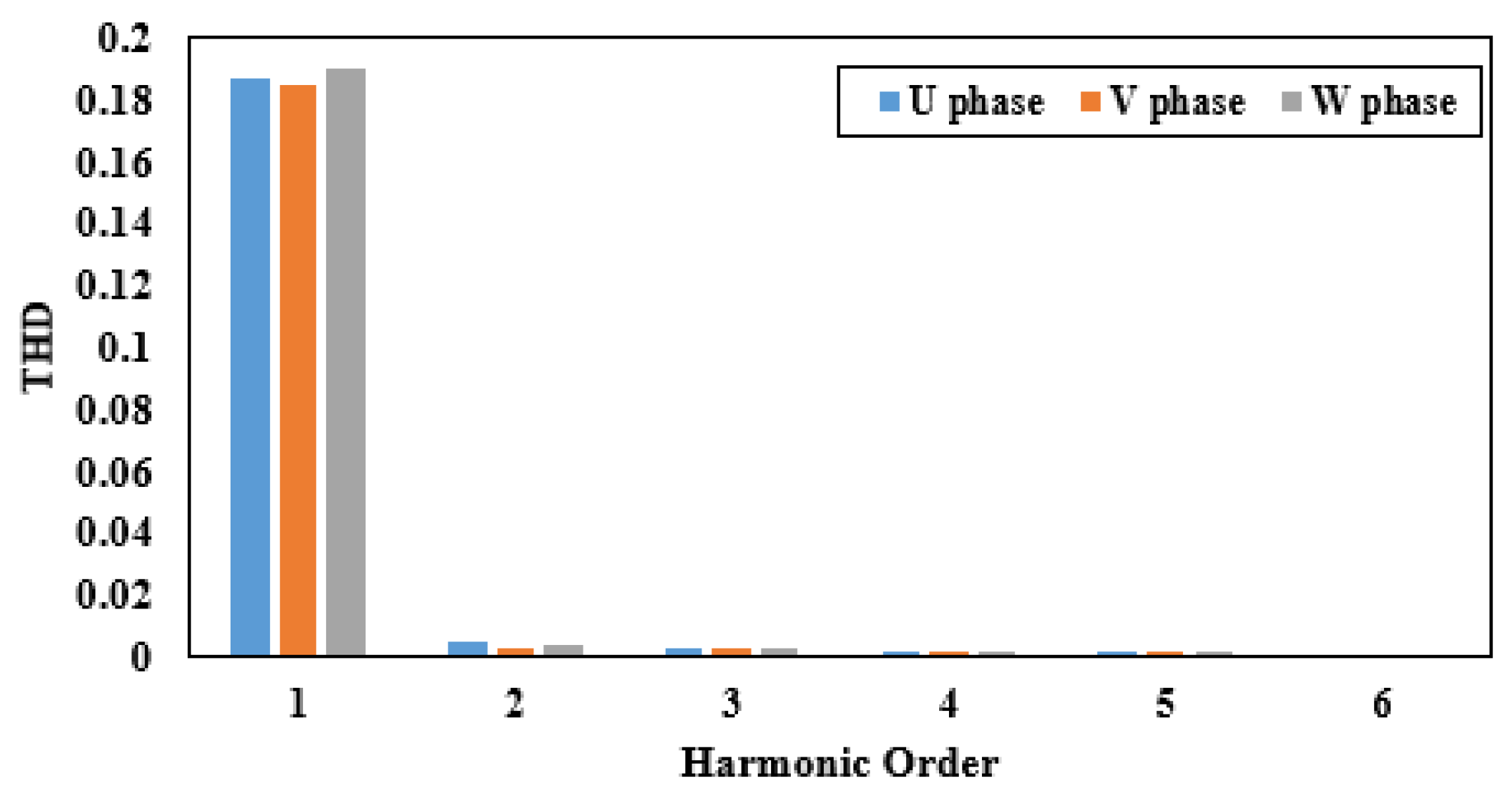
Figure 7 represents the no-load flux linkage of the machine while Figure 8 represents its harmonics. It can be observed that all the phases are purely sinusoidal, and the difference between the positive peaks of the phases is not considerable, showing lower or no end effect. The difference between the positive and negative peaks is present, which is a sign of leakage flux or saturation. Thrust force density ( T F d ) of the machine is calculated using Equation (5), where T F a v e r a g e represents the average thrust force, and V m represents the volume of the machine.
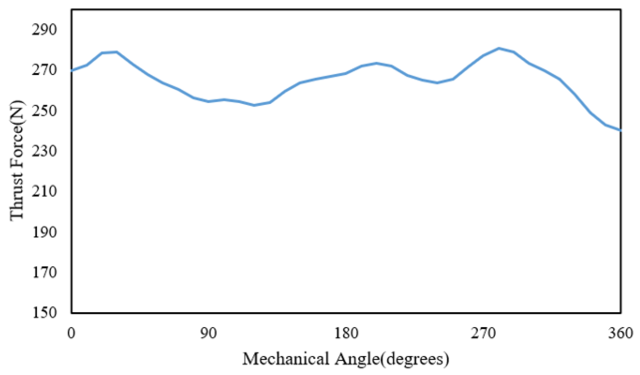
Figure 9 shows detent force for the proposed HEDSLFSM. It is a no-load force between the stator pole and mover slot, which either pulls or pushes the mover. If the detent force is positive, it pushes the machine forward, and if it is negative, it pulls the machine backward. This push and pull causes ripples in the thrust force and the overall ripple rate increases. HEDSLFSM experiences a bipolar detent force, whereas the thrust force is unidirectional (x-axis). The detent force’s influence can be observed from Figure 10; when the detent force increases in the positive direction, the thrust force also increases, and when the detent force decreases and attains a negative value, the thrust force also decreases.
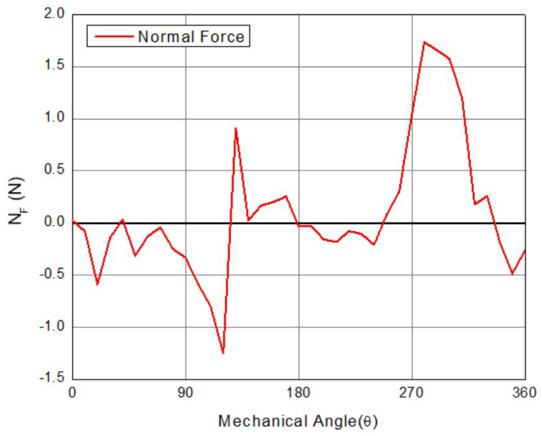
Attraction or repulsion between the mover and the stator is represented by normal force ( N F ), which adds frictional forces and puts an extra burden on the bearing system. N F is presented in Figure 11; which has an average value of zero because of the double-sided nature of the HEDSLFSM. N F is attractive; as can be seen from the value, because of the increased magnitude of negative flux linkage compared to positive.
The current density of the machine also plays an important role in the machine’s performance and is one of the key performance parameters in performance analysis. The machine’s performance is analyzed at different current densities to check whether or not the machine is saturated. HEDSLFSM is analyzed at different current densities, and the performance is observed. Figure 12 shows TF at different current densities. It can be seen that initially, the line increases linearly, but after a point, it loses its linearity because the machine is moving toward the saturation region. The machine’s current density is calculated using Equation (6), where S is the slot area, I is the RMS current ς is the filling factor.
J a = N I S ς
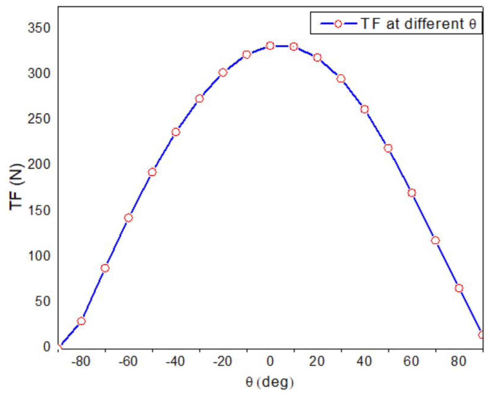
The performance of the machine is analyzed and observed at different starting angles. Starting angle is the phase angle of applied current to the machine at which the thrust force is produced. If the angle is changed, the machine’s performance helps to evaluate the dynamic performance of the machine. It can be seen from Figure 13 that the machine performs best at starting angle 0.

5. Optimization of Geometric Variables

Two types of optimization techniques have been applied to increase the TF and improve the machine’s performance. For parameters like S.R, A C w , D C w , and PM, a geometric optimization technique is used, and for S T W , S S , α , and θ , JMAG inbuilt Genetic Optimization technique is employed, and the respective parameters are optimized.

5.1. Geometric Optimization

Single variable geometric optimization is used, which leads to a sequential solution of various geometric variables. It is advantageous because it reduces the computational complexity and time required for optimization. Being sequential in nature, the optimization variables are entirely independent of the previous value. 
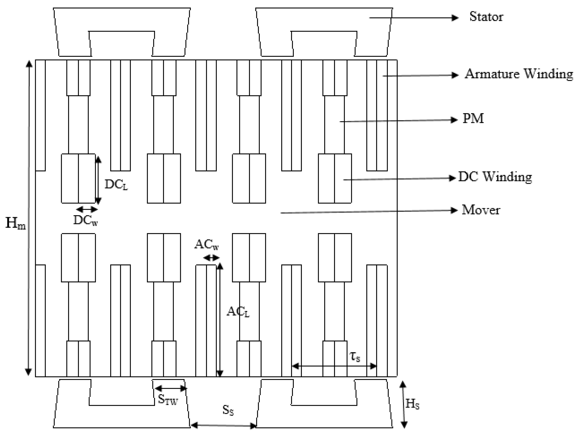
Figure 14 shows the flow chart for geometric optimization. S.R is the ratio between the height of the stator to the height of the whole machine and is calculated using Equation (7).
S . R = H s + 2 L g H s + H m + 2 L g
H s represents the stator’s height, H m is the mover height, and L g represents the airgap’s length. Different S.R values are considered, and their influence on the performance parameters like TF, F d , and φ p p is observed. TF is considered as the main priority in optimization. Table 3 shows the detail of split ratio optimization and analysis. It can be seen that the TF increases up to S.R of 0.20; after that, the TF tends to decrease, with the maximum thrust force being observed at S.R of 0.20 with φ p p of 0.8 Wb.
A higher value of split ratio means a bigger stator width, which increases the iron losses and the machine’s manufacturing cost. The lower value of the split ratio means a bigger mover that increases the mover mass. Therefore, the bearing system efficiency decreases, and iron losses and iron volume increases, thereby lowering the machine’s overall efficiency.
The winding slot area for both DC and AC is optimized using geometric optimization. The slot area is selected according to the number of conductors to be placed. Additionally, the current density of the machine has a role in selecting the slot area. Since the current density cannot be increased from a certain limit as the machine gets saturated, the slot area cannot be increased from a certain value. A higher slot area also decreases the mover’s teeth’ width and thereby leads it to saturate. Table 4 shows the detailed optimization of the slot area.

5.2. Genetic Optimization

Parameters such as STW, S S , and α are optimized using JMAG in-built optimization technique. The objective function and constraints are given in 
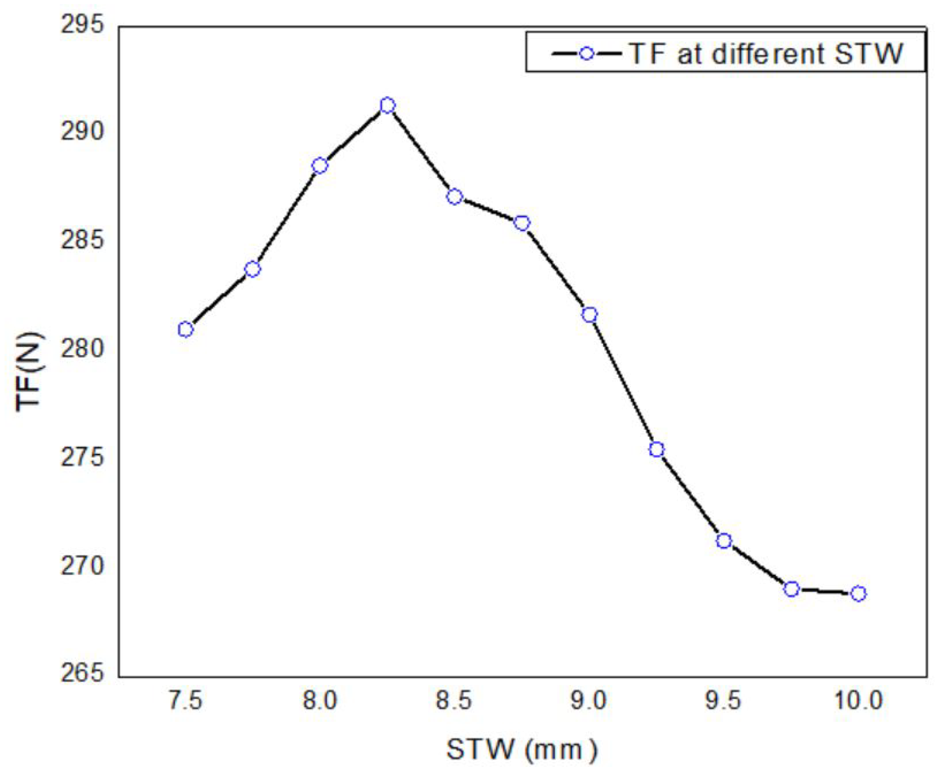
Table 5. Optimal selection of STW of the machine mainly influences the coil flux linkage, affecting the machine’s thrust force. If the tooth width is reduced too much, it affects both the flux linkage, as it either goes to saturation or the flux linkage value decreases. If the width is increased, it increases the iron losses and manufacturing cost of the machine. Figure 15 shows the influence of the STW on the average thrust force of the machine. A maximum TF of 291.36 N is observed at 8.33 mm, so it is considered.
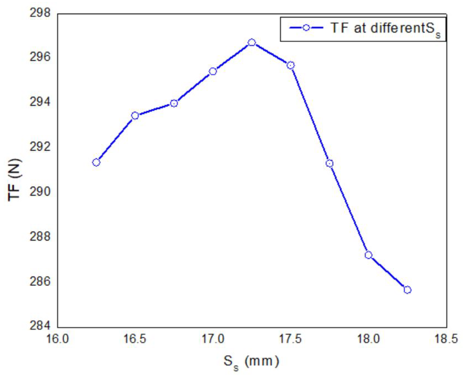
Since the stator is in the form of U-shaped modules, the optimal placement of these modules is very important to have a good flux linkage. Spacing between the module is optimized, and its effect on the overall thrust force is observed. It can be seen from Figure 16 that initially, the TF increases with the increase in the spacing of the module since the flux linkage increases, but after a certain point, a gradual decrease in the thrust force can be observed. Maximum TF of 296.72 N at 17.01 mm.
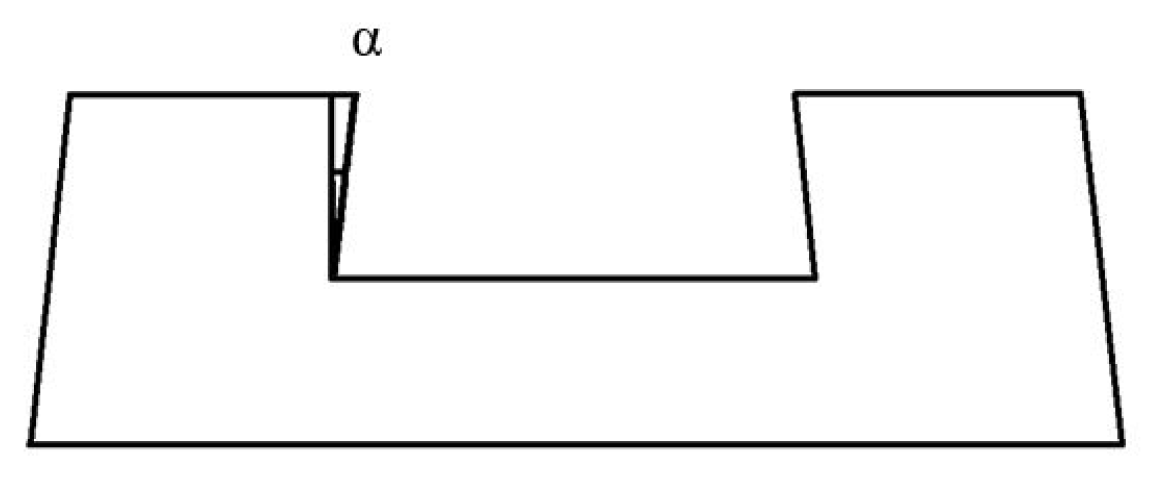
The crooked angle is the angle between the inside of the stator tooth and the yoke of the stator. It is optimized to increase the alignment of the mover slot and stator pole; thus, the TF also increases. TF increases linearly from 0 to 6 , and then a decrease in the TF is noted. Maximum TF is observed at 6 . Figure 17 represents a crooked angle, while Figure 18 shows how the crooked angle influences the average thrust force.
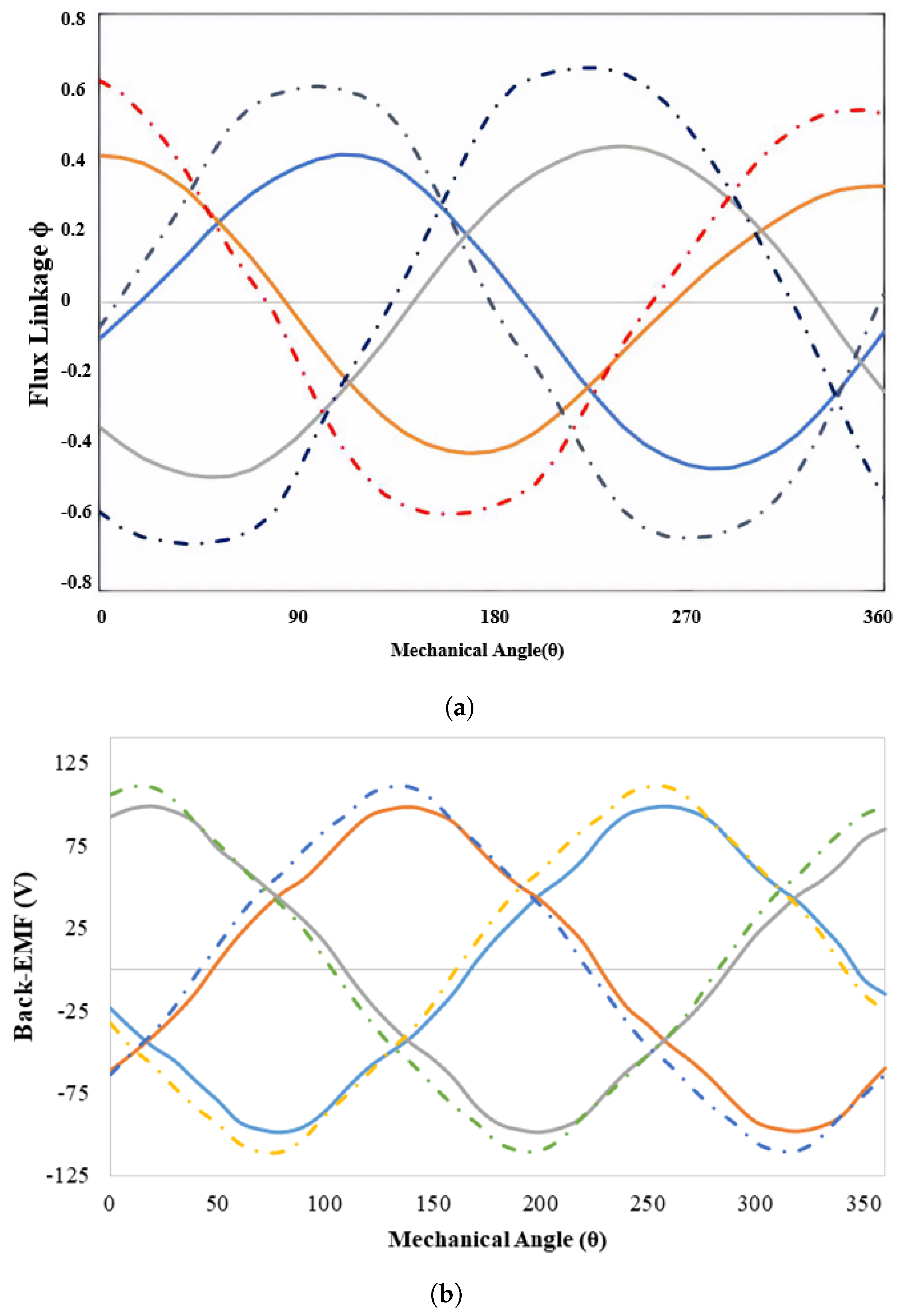
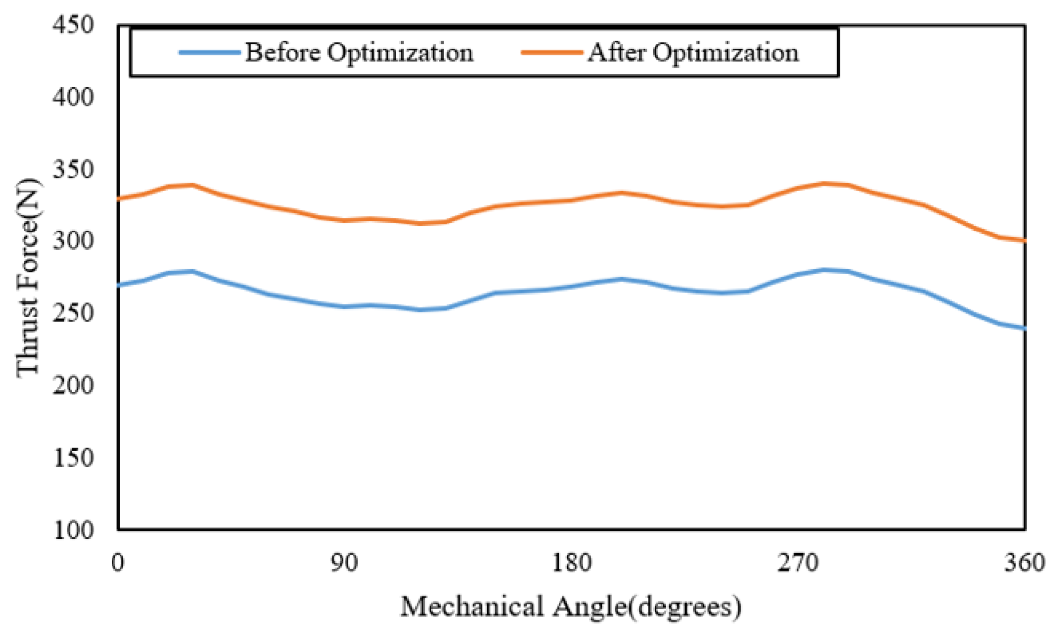
Table 6 presents the detail of all the optimization and the resultant change in key performance parameters such as TF, F d , and φ p p . Comparison of initial and final φ p p and back-EMF is shown in Figure 19a,b, respectively. The initial and optimized TF is shown in Figure 20. A clear difference between the initial and final can be observed.

6. Efficiency Analysis

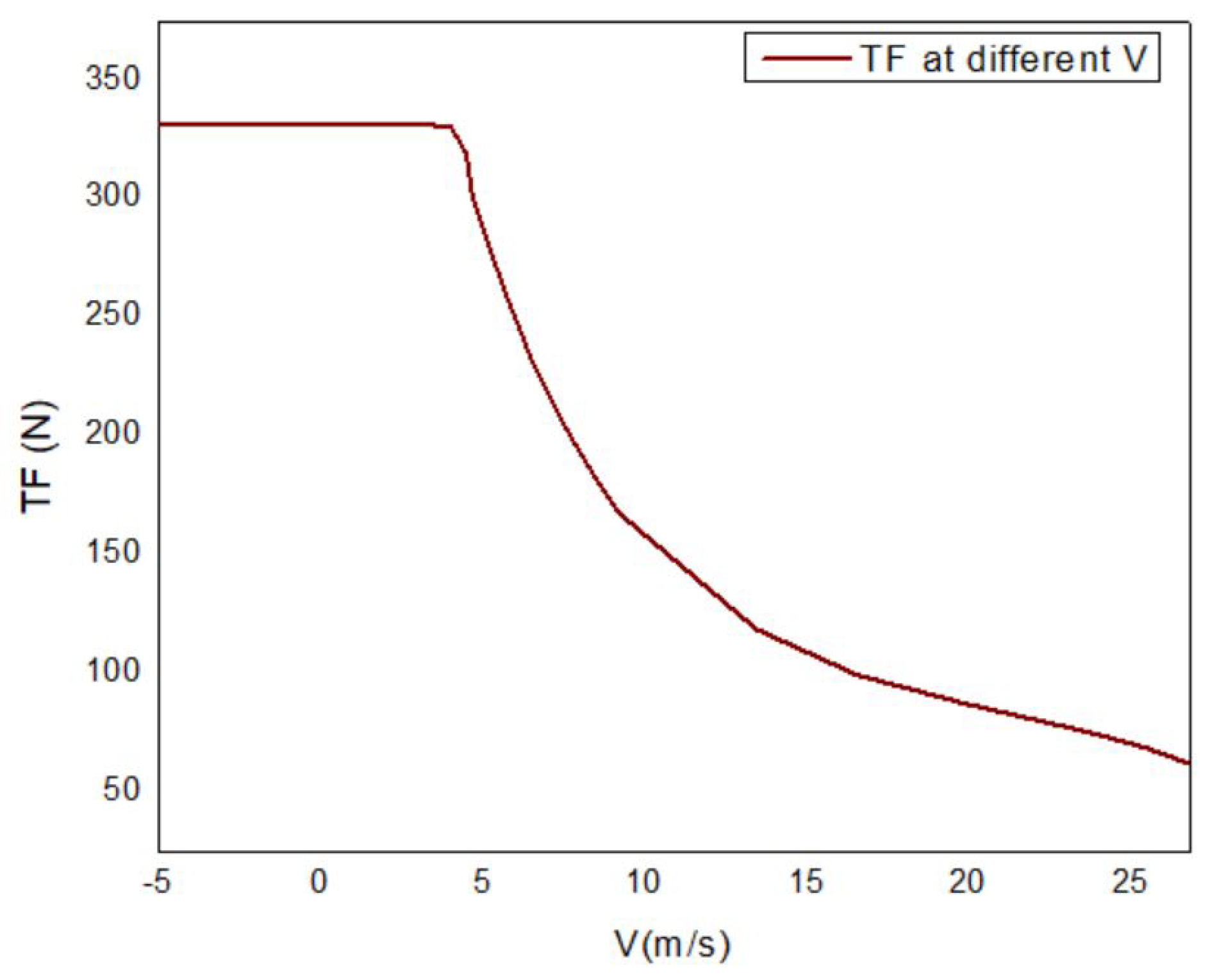
The machine’s performance is observed at different velocities, and the resultant TF of the machine is noted. 
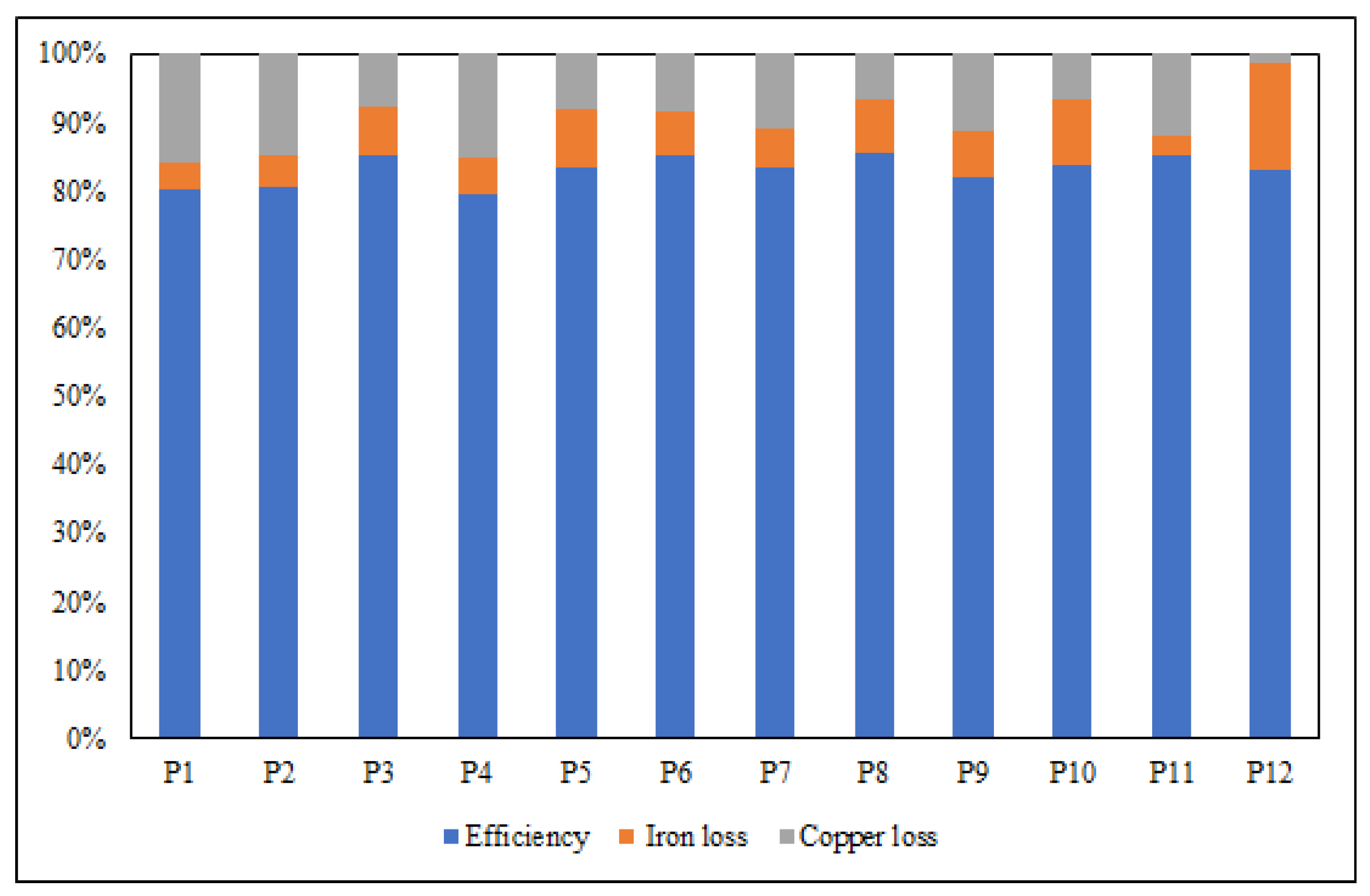
Figure 21 shows TF at different velocities. Several points in the TF vs. Velocity graph are considered for efficiency calculation, and the resultant efficiency of the machine is calculated. Figure 22 shows the resulting iron losses, copper losses, and the machine’s efficiency at that selected point. Points selected in the thrust force vs. velocity curve are represented across the x-axis, and efficiency at that specific point is represented on the y-axis. At point 1, the copper and iron losses of 278 W and 153 W are calculated while at point 12, the iron losses were at a maximum (approximately 309 W), and hence efficiency is lower at these two points. The machine’s overall efficiency is calculated by taking the average of the efficiencies observed at various points. The average efficiency of the proposed machine at different points is 83%. The relation between velocity and output power is shown in Figure 23 and the proposed machine has a power factor of 0.76 lagging under loaded condition.
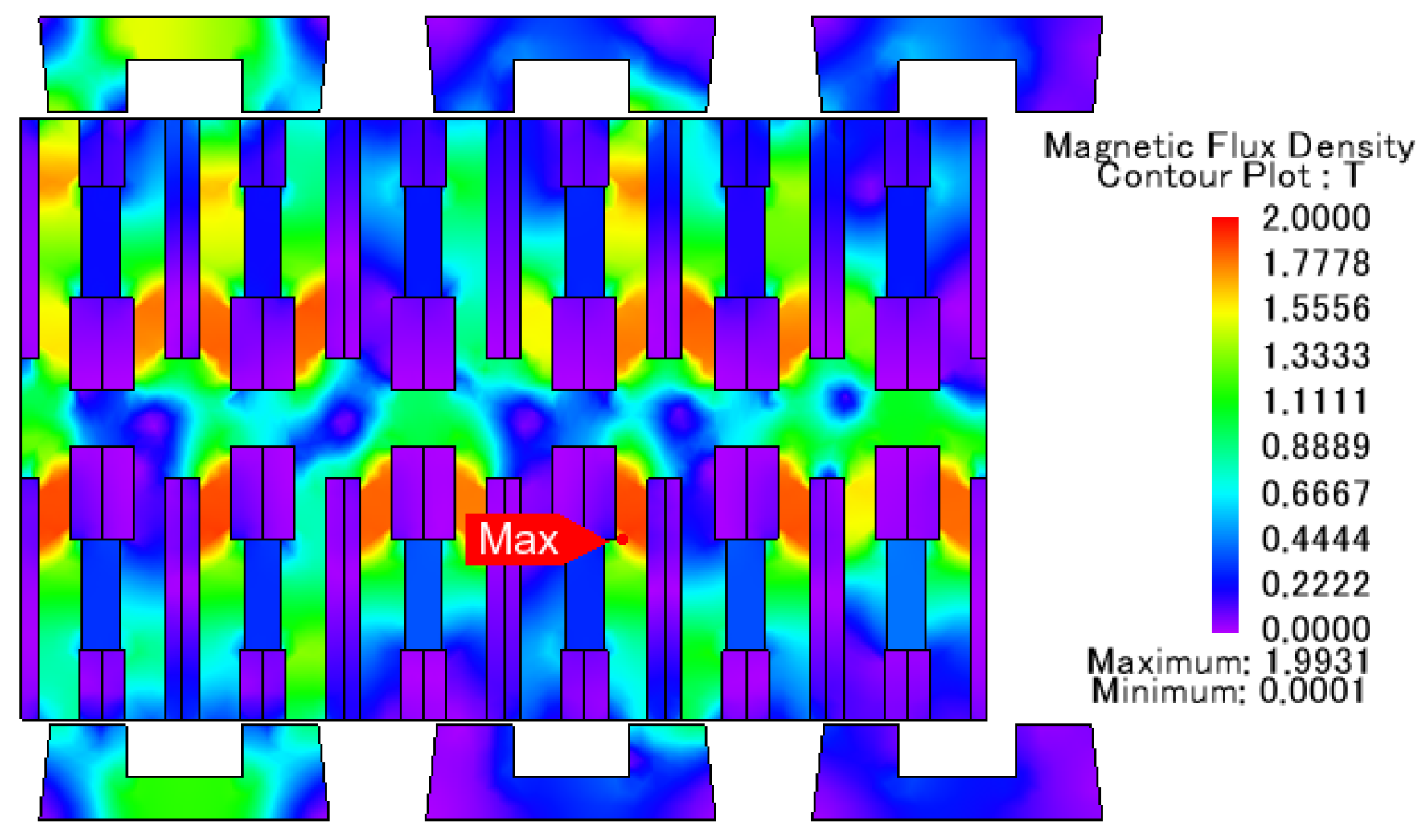
A nephogram represents the flux distribution of the machine in Figure 24. It can be seen from Figure 24 that flux is distributed uniformly over the whole machine, and only a significantly lower value of saturation can be observed. The maximum flux density observed in the stator is 1.3 T, while the mover is 1.7 T.

7. Thermal Analysis

The machine’s thermal analysis is mainly divided into two parts; firstly, thermal analysis of the machine is carried out by FEA analysis. Secondly, Lumped Parametric Model of the machine is built and compared with the FEA analysis.

7.1. FEA Thermal Analysis

FEA’s thermal analysis comprises two main studies; in the first step, we calculate all the losses occurring in the machine, and in the second part, we used these losses as heat sources. The magnetic study of the machine is considered, and the necessary condition for the magnetic and electric field is selected. Losses in the form of iron and copper losses are calculated, and then a 3D thermal study of the machine is initiated. Different machine parts generate different heat, so the copper losses are assigned to the winding, and iron losses are assigned to the machine’s core. Since all the machine’s excitation sources are in the mover and the stator has no excitation source, its temperature does not increase considerably. The machine’s various faces are considered heat transfer boundaries, and the thermal conductivity of each part is set accordingly. The temperature distribution of the proposed machine obtained from 3D FEA thermal study is shown in Figure 25.

7.2. Thermal Analysis by LPMC

LPMC of the machine validates thermal analysis done by FEA. The LPMC model is built by dividing the machine into isometric parts, and then each part is represented by an equivalent thermal resistance. For transient state analysis, thermal storage devices in the form of capacitors are added. The thermal resistance of each part is proportional to the width of the part and inversely proportional to the thermal conductivity of the individual part. Few assumptions have been considered while developing the equivalent model, which are given below:
1.
2D thermal analysis is considered; therefore, heat transfer in X and Y directions is considered while heat flow in the Z direction is ignored;
2.
Parts are considered isometric; therefore, heat distribution is uniform;
3.
Thermal resistances due to contact between two parts/contact thermal resistance are not considered as they are assumed to be soft;
4.
Only two ways (i.e., conduction and convection) of heat transfer are considered, and the heat radiation is not considered;
5.
As the machine’s stator has no excitation source, and there is an air gap between the mover and the stator, its temperature does not increase considerably. It is therefore neglected in the modeling process.
Since the machine is divided based on the nature of the material, different thermal resistances are calculated for each part. Figure 26 shows several heat transfer boundaries. Figure 27 shows the machine’s division, and Figure 28 shows the machine’s LPMC model based on the division considered. The machine can be best divided into three parts because of upper DC, PM, and lower DC. The armature winding part is divided into two equal parts.
Resistances of the model are calculated using the following equations [27], and the thermal conductivities of each part are given in Table 7.
R i 1 x = l i x 1 λ f e l i y 1 L a , R i 1 y = 0.5 l i y 1 λ f e l i x 1 L a
R i 2 x = l i x 2 λ f e l i y 2 L a , R i 2 y = 0.5 l i y 2 λ f e l i x 2 L a
R i 3 x = l i x 3 λ f e l i y 3 L a , R i 3 y = 0.5 l i y 3 λ f e l i x 3 L a
R i 4 x = l i x 4 λ f e l i y 4 L a , R i 4 y = 0.5 l i y 4 λ f e l i x 4 L a
R m = l m y 3 λ P M l m x L a
The transient state of the machine uses capacitors as temperature storage units. They are selected based on the type and nature of the material (part) of the machine. The size of the capacitor is calculated using equation:
C = m × C P
where C represents the capacitance of the capacitor, and m is the mass of the part, which can be calculated from the material’s density and volume. C p represents the thermal conductivity of the material. After calculating all the variables, a complete model is simulated using SIMULINK software, and temperatures at different points and the overall temperature of the whole machine is analyzed.

7.3. Comparison of FEA and LPMC

Thermal analysis done via FEA analysis is compared with the LPMC analysis and is represented in the form of a graph shown in Figure 29 and Figure 30. It can be observed from the graph that a good agreement between the two analyses exists, and the LPMC model completely validates the FEA analysis.
Figure 29 shows temperature rise at various points of the machine and how it rises over time. Since copper loss is the primary source of temperature rise in the machine, those areas have the highest temperature, and the temperature rises more quickly than the rest of the machine. In Figure 30, the overall comparison of the temperature rise observed from both the analysis is presented. A good agreement between the two methods is observed with an error percentage of less than 4 % .

8. Conclusions

A HEDSLFSM is proposed with a U-Shaped module stator. The U-shaped modular stator reduces the machine’s manufacturing cost and lowers the overall iron losses of the machine. Genetic and geometric optimization techniques are used to optimize the leading geometry parameters of the proposed design. A comparison between initial and optimized values is made for all the design variables. After the optimization, an increase of 26.81% in TF and 50% in φ p p was observed. Thermal analysis of the machine is performed via FEM and then validated by developing an LPMC model in Simulink, in which an equivalent thermal resistor represents each part. The LPMC model completely validates the FEM analysis, and both agree with an error percentage of less than 4%.

Author Contributions

Conceptualization, H.U.J. and F.K.; methodology, H.U.J.; software, H.U.J., B.U., M.Q.; validation, H.U.J., B.U., M.Q., M.A.K.; resources, F.K., G.H., F.R.A.; formal analysis, B.U., H.U.J.; original draft preparation, H.U.J.; visualization, B.U.; review and editing, B.U., F.K.; supervision, F.K.; project administration, F.K., F.R.A.; funding acquisition, F.R.A., G.H. All authors have read and agreed to the published version of the manuscript.

Funding

The APC of this manuscript is funded by Taif University Researchers Supporting Project Number(TURSP-2020/331), Taif University, Taif, Saudi Arabia.

Institutional Review Board Statement

Not applicable.

Informed Consent Statement

Not applicable.

Data Availability Statement

Not applicable.

Acknowledgments

The authors would like to acknowledge COMSATS University Islamabad, Abbottabad Campus and Higher Education Commission of Pakistan (No. TDF-03-067/R&D/HEC/2019) in part with Taif University Researchers Supporting Project Number(TURSP-2020/331), Taif University, Taif, Saudi Arabia.

Conflicts of Interest

The authors declare no conflict of interest.

Abbreviations

The following abbreviations are used in this manuscript:
S.RSplit Ratio
G.A.Genetic Algorithm
STWStator Tooth Width
HEDSLFSMHybrid Excited Double-Sided Linear Flux Switching Machine
DCwDC winding slot area
ACwAC winding slot area
TFThrust Force
LPMCLumped Parametric Magnetic Equivalent Circuit
HEVsHybrid Electric Vehicles
LIMsLinear Induction machines
LFSMsLinear Flux Switching Machines
SLFSMSingle-Sided LFSM
DSLFSMDouble-sided LFSM
PMLFSMsPermanent Magnet LFSMs
HELFSMsHybrid Excited LFSMs

References

  1. Walsh, M.; Abbruzzo, G.; Hickey, S.; Ramirez-Garcia, S.; O’Flynn, B.; Torres, J. On the potential for electromagnetic energy harvesting for a linear synchronous motor based transport system in factory automation. In Proceedings of the 2019 24th IEEE International Conference on Emerging Technologies and Factory Automation (ETFA), Zaragoza, Spain, 10–13 September 2019; pp. 864–869. [Google Scholar]
  2. Hu, D.; Xu, W.; Dian, R.; Liu, Y.; Zhu, J. Loss minimization control of linear induction motor drive for linear metros. IEEE Trans. Ind. Electron. 2017, 65, 6870–6880. [Google Scholar] [CrossRef]
  3. Shen, Y.; Lu, Q.; Li, H.; Cai, J.; Huang, X.; Fang, Y. Analysis of a novel double-sided yokeless multitooth linear switched-flux pm motor. IEEE Trans. Ind. Electron. 2017, 65, 1837–1845. [Google Scholar] [CrossRef]
  4. Ullah, N.; Khan, M.K.; Khan, F.; Basit, A.; Ullah, W.; Ahmad, T.; Ahmad, N. Comparison of analytical methodologies for analysis of single sided linear permanent magnet flux switching machine: No-load operation. Appl. Comput. Electromagn. Soc. J. 2018, 33, 923–930. [Google Scholar]
  5. Xiao, F.; Du, Y.; Sun, Y.; Zhu, H.; Zhao, W.; Li, W.; Ching, T.; Qiu, C. A novel double-sided flux-switching permanent magnet linear motor. J. Appl. Phys. 2015, 117, 17B530. [Google Scholar] [CrossRef]
  6. Zahid, A.; Khan, F.; Ullah, N.; Fatima, A.; Ahmad, N.; Ullah, W.; Khan, M. Performance comparison of novel double sided yokeless multitooth permanent magnet flux switching machine. In Proceedings of the 2019 International Conference on Engineering and Emerging Technologies (ICEET), Lahore, Pakistan, 21–22 February 2019; pp. 1–6. [Google Scholar]
  7. Zhong, W.; Yu, H.; Hu, M.; Shi, Z.; Liu, Q. Study on a novel pseudo-sixphase linear flux-switching permanent-magnet machine for direct drive. IEEE Trans. Appl. Supercond. 2016, 26, 1–4. [Google Scholar] [CrossRef]
  8. Ullah, B.; Khan, F.; Milyani, A.H.; Ahmad, N.; Cheema, K.M. Design and analysis of dual-stator hybrid excited linear flux switching machine for long-stroke applications. IET Electr. Power Appl. 2021. [Google Scholar] [CrossRef]
  9. Zhu, Z.; Lu, Q.; Li, H.; Huang, X.; Ye, Y. Research on yokeless doublesided multi-tooth flux-switching linear motor. Compel Int. J. Comput. Math. Electr. Electron. Eng. 2016, 35, 832–843. [Google Scholar]
  10. Zhang, B.; Cheng, M.; Wang, J.; Zhu, S. Optimization and analysis of a yokeless linear flux-switching permanent magnet machine with high thrust density. IEEE Trans. Magn. 2015, 51, 1–4. [Google Scholar] [CrossRef] [PubMed]
  11. Fan, H.; Chau, K.; Liu, C.; Cao, L.; Ching, T. Quantitative comparison of novel dual-pm linear motors for ropeless elevator system. IEEE Trans. Magn. 2018, 54, 1–6. [Google Scholar]
  12. Abdollahi, S.E.; Vaez-Zadeh, S. Back EMF analysis of a novel linear flux switching motor with segmented secondary. IEEE Trans. Magn. 2013, 50, 1–9. [Google Scholar] [CrossRef]
  13. Tan, Q.; Wang, M.; Li, L. Analysis of a new flux switching permanent magnet linear motor. IEEE Trans. Magn. 2020, 57, 8201705. [Google Scholar] [CrossRef]
  14. Cao, R.; Jin, Y.; Lu, M.; Zhang, Z. Quantitative comparison of linear fluxswitching permanent magnet motor with linear induction motor for electromagnetic launch system. IEEE Trans. Ind. Electron. 2018, 65, 7569–7578. [Google Scholar] [CrossRef]
  15. Du, K.; Zhao, W.; Xu, L.; Ji, J. Design of a new fault-tolerant linear permanent-magnet vernier machine. IEEE J. Emerg. Sel. Top. Ind. Electron. 2020, 1, 172–181. [Google Scholar] [CrossRef]
  16. Khan, F.; Sulaiman, E.; Ahmad, M.Z. A novel wound field flux switching machine with salient pole rotor and non over lapping windings. Turk. J. Electr. Eng. Comput. Sci. 2017, 25, 950–964. [Google Scholar] [CrossRef]
  17. Tan, Q.; Wang, M.; Li, L.; Li, J. Pulsating magnetic field of permanent magnet linear synchronous motor and its influence on detent force. IEEE Trans. Energy Convers. 2020, 36, 703–712. [Google Scholar] [CrossRef]
  18. Zhang, C.; Zhang, L.; Huang, X.; Yang, J.; Shen, L. Research on the method of suppressing the end detent force of permanent magnet linear synchronous motor based on stepped double auxiliary pole. IEEE Access 2020, 8, 112539–112552. [Google Scholar] [CrossRef]
  19. Hao, W.; Wang, Y. Thrust force ripple reduction of two c-core linear flux switching permanent magnet machines of high thrust force capability. Energies 2017, 10, 1608. [Google Scholar] [CrossRef] [Green Version]
  20. Qasim, N.; Basit, A.; Ullah, N.; Khan, F.; Ullah, W.; Umair, M. Influence of stator design on the thrust force performance of double sided linear permanent magnet flux switching machine. In Proceedings of the 2020 3rd International Conference on Computing, Mathematics and Engineering Technologies (iCoMET), Sukkur, Pakistan, 29–30 January 2020; pp. 1–9. [Google Scholar]
  21. Cao, R.; Su, E.; Lu, M. Comparative Study of Permanent Magnet Assisted Linear Switched Reluctance Motor and Linear Flux Switching Permanent Magnet Motor for Railway Transportation. IEEE Trans. Appl. Supercond. 2020, 30, 1–5. [Google Scholar] [CrossRef]
  22. Mallik, S. Efficiency and Cost Optimized Design of an Induction Motor Using Genetic Algorithm. IEEE Trans. Ind. Electron. 2017, 64, 9854–9863. [Google Scholar] [CrossRef]
  23. Li, G.; Ojeda, J.; Hoang, E.; Gabsi, M.; Lecrivain, M. Thermal–electromagnetic analysis for driving cycles of embedded flux switching permanent-magnet motors. IEEE Trans. Veh. Technol. 2011, 61, 140–151. [Google Scholar] [CrossRef]
  24. Sun, X.; Cheng, M.; Zhu, S.; Zhang, J. Coupled Electromagnetic-Thermal-Mechanical Analysis for Accurate Prediction of Dual-Mechanical-Port Machine Performance. IEEE Trans. Ind. Appl. 2012, 48, 2240–2248. [Google Scholar] [CrossRef]
  25. Thomas, A.S.; Zhu, Z.Q.; Li, G.J. Thermal Modelling of Switched Flux Permanent Magnet Machines. In Proceedings of the International Conference on Electrical Machines (ICEM), Berlin, Germany, 2–5 September 2014; pp. 2212–2217. [Google Scholar]
  26. Cai, X.; Cheng, M.; Zhu, S.; Zhang, J. Thermal modeling of flux-switching permanent-magnet machines considering anisotropic conductivity and thermal contact resistance. IEEE Trans. Ind. Electron. 2016, 63, 3355–3365. [Google Scholar] [CrossRef]
  27. Amoros, J.G.; Andrada, P.; Blanque, B. An analytical approach to the thermal design of a double-sided linear switched reluctance motor. In Proceedings of the XIX International Conference on Electrical Machines, Rome, Italy, 6–8 September 2010; pp. 1–4. [Google Scholar] [CrossRef]
Figure 1. Proposed model (a) 2D (b) 3D.
Energies 14 08511 g001
Figure 2. Parameters of the proposed model.
Energies 14 08511 g002
Figure 3. Flux linkage (PM excitation only) (a) Flux lines (b) Contour plot.
Energies 14 08511 g003
Figure 4. Flux linkage (DC excitation only) (a) flux lines, (b) contour plot.
Energies 14 08511 g004
Figure 5. Flux linkage (both PM and DC excitation) (a) flux lines, (b) contour plot.
Energies 14 08511 g005
Figure 6. Winding configuration of the proposed model.
Energies 14 08511 g006
Figure 7. No-load flux linkage of the proposed model.
Energies 14 08511 g007
Figure 8. Frequency spectrum representation.
Energies 14 08511 g008
Figure 9. Detent force of the proposed model.
Energies 14 08511 g009
Figure 10. TF at different mechanical angles.
Energies 14 08511 g010
Figure 11. Normal force at different mechanical angles.
Energies 14 08511 g011
Figure 12. TF at different current densities.
Energies 14 08511 g012
Figure 13. Thrust force at different starting angles.
Energies 14 08511 g013
Figure 14. Flow chart of geometric optimization.
Energies 14 08511 g014
Figure 15. Influence of stator tooth width on TF.
Energies 14 08511 g015
Figure 16. Influence of spacing between the module on TF.
Energies 14 08511 g016
Figure 17. Crooked angle ( α ).
Energies 14 08511 g017
Figure 18. Influence of α on TF.
Energies 14 08511 g018
Figure 19. (a) Comparison between initial and optimized φ p p (b) back-EMF.
Energies 14 08511 g019
Figure 20. Comparison between initial and optimized TF.
Energies 14 08511 g020
Figure 21. TF at different velocities.
Energies 14 08511 g021
Figure 22. Efficiency at different velocities.
Energies 14 08511 g022
Figure 23. Power at different velocities.
Energies 14 08511 g023
Figure 24. Flux distribution of the machine.
Energies 14 08511 g024
Figure 25. Temperature distribution of the machine.
Energies 14 08511 g025
Figure 26. Heat transfer boundaries.
Energies 14 08511 g026
Figure 27. Machine division based on the nature of the material.
Energies 14 08511 g027
Figure 28. LPMC model of the machine.
Energies 14 08511 g028
Figure 29. Temperature variation at different points of the machine.
Energies 14 08511 g029
Figure 30. Overall comparison of the FEA and LPMC model.
Energies 14 08511 g030
Table 1. Detailed design parameter of the proposed model.
ParametersValues
Pole Pitch, τ s 26.1984 mm
Velocity, V4 m/s
Stator Height, H s 12.56 mm
Stack Length90 mm
Mover Height, H m 106.88 mm
Mover Pole Width5.197 mm
Stator Tooth Width, S T W 8.33 mm
Air gap, L g 0.8 mm
Maximum Current density in Armature, J a 22 A/mm2
Maximum Current Density in FEC, J e 10 A/mm2
Armature Winding Turns136
Maximum Current DC5.76 A
Ferrite MagnetBr = 0.4T
Split Ratio, S.R0.20
Armature Slot Width, A C w 2.6 mm
Armature Slot Length, A C L 28.8 mm
PM Volume, P M v 6950.25 mm3
Stator Yoke, S y 5.96 mm
Stator Module Spacing, S s 17.01 mm
Table 2. Different combinations and their respective TF.
Pole/Slot CombinationAverage Thrust ForceDetent Force
5/6273 N15 N
6/7250 N30 N
Table 3. Split ratio optimization.
S.RTF F d THD φ p p ( wb )
0.15256.11 N33.90 N16.1%0.7
0.18259.72 N35.17 N14.4%0.73
0.20261.09 N27.56 N15.67%0.8
0.24260.89 N31.79 N19.1%0.82
0.25257.27 N36.21 N13.97%0.75
0.30251.078 N29 N16.56%0.79
Table 4. Slot area optimization.
ParametersOptimization Values
A C w Width2.4 mm2.5 mm2.6 mm2.7 mm2.8 mm
A C w Length31.25 mm30 mm28.8 mm27.7 mm26.78 mm
D C w Width4.1 mm4.2 mm4.3 mm4.4 mm4.5 mm
D C w Length13.17 mm12.85 mm12.55 mm12.27 mm12 mm
TF261.72 N264.31 N271.45 N265.07 N263.12 N
Fd27.56 N28.04 N26.31 N29.12 N27.65 N
Table 5. Constraints for genetic optimization.
Design ParameterConstraintsObjective Function
STW7 mm ≤ STW ≤ 13 mm(Max TF,TFd) and Min (Fd)
SS11 mm ≤ SS ≤ 20 mm(Max TF,TFd) and Min (Fd)
Table 6. Detail of overall optimization.
ParametersInitalFinalTF BeforeTF After F d Before F d After
S.R0.240.20260.89261.3131.79 N27.56 N
A C w L30 mm28.8 mm261.31 N268.21 N27.5628.71 N
A C w W2.5 mm2.6 mm261.31 N268.21 N27.5628.71 N
D C w L12.85 mm12.55 mm268.21 N271.4528.71 N26.31
D C w W4.2 mm4.3 mm268.21 N271.4528.7126.31 N
STW10.1 mm8.33 mm271.45291.36 N26.7128.02 N
S S 13 mm17.01 mm291.36 N296.72 N28.0229.54 N
α 0 6 296.72331.89 N29.5422.89 N
Table 7. Thermal conductivity of various parts.
VariableThermal Conductivity
λ f e 9 W/m °C
λ c u 28 W/m °C
λ P M 0.68 W/m °C
λ c u 28 W/m °C
Density of iron, ρ i 7870 Kg/m3
Density of copper, ρ c 8940 Kg/m3
Density of ferrite magnet, ρ P M 5000 Kg/m3
Publisher’s Note: MDPI stays neutral with regard to jurisdictional claims in published maps and institutional affiliations.

