
The Analytical Comparative Analysis of Electromagnetic Characteristics of Four Typical Radial Flux Permanent Magnet Eddy Current Couplers

 , ,
, ,
Abstract
:1. Introduction
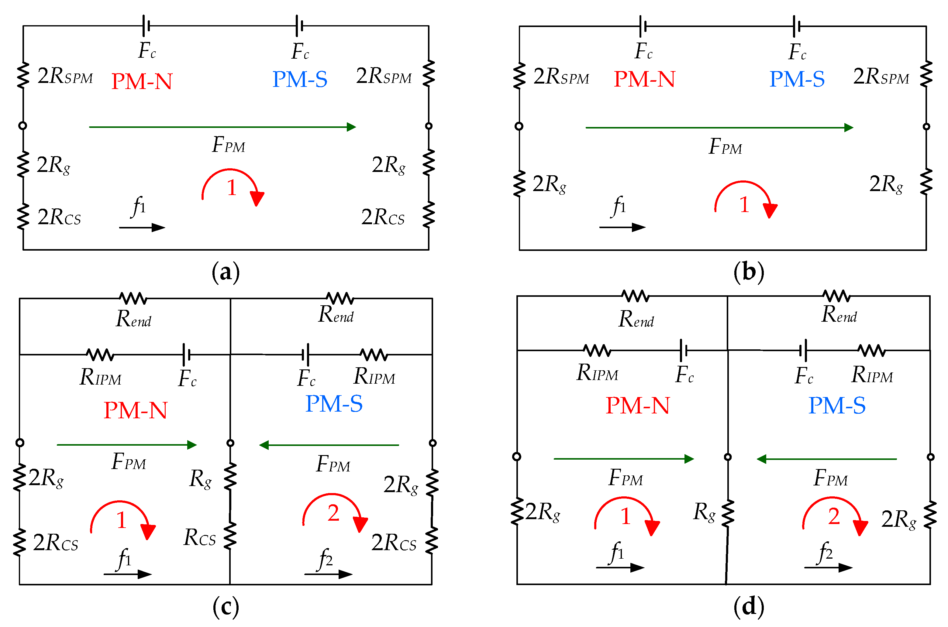
2. The Magnetomotive Force (MMF) and Permeance Model
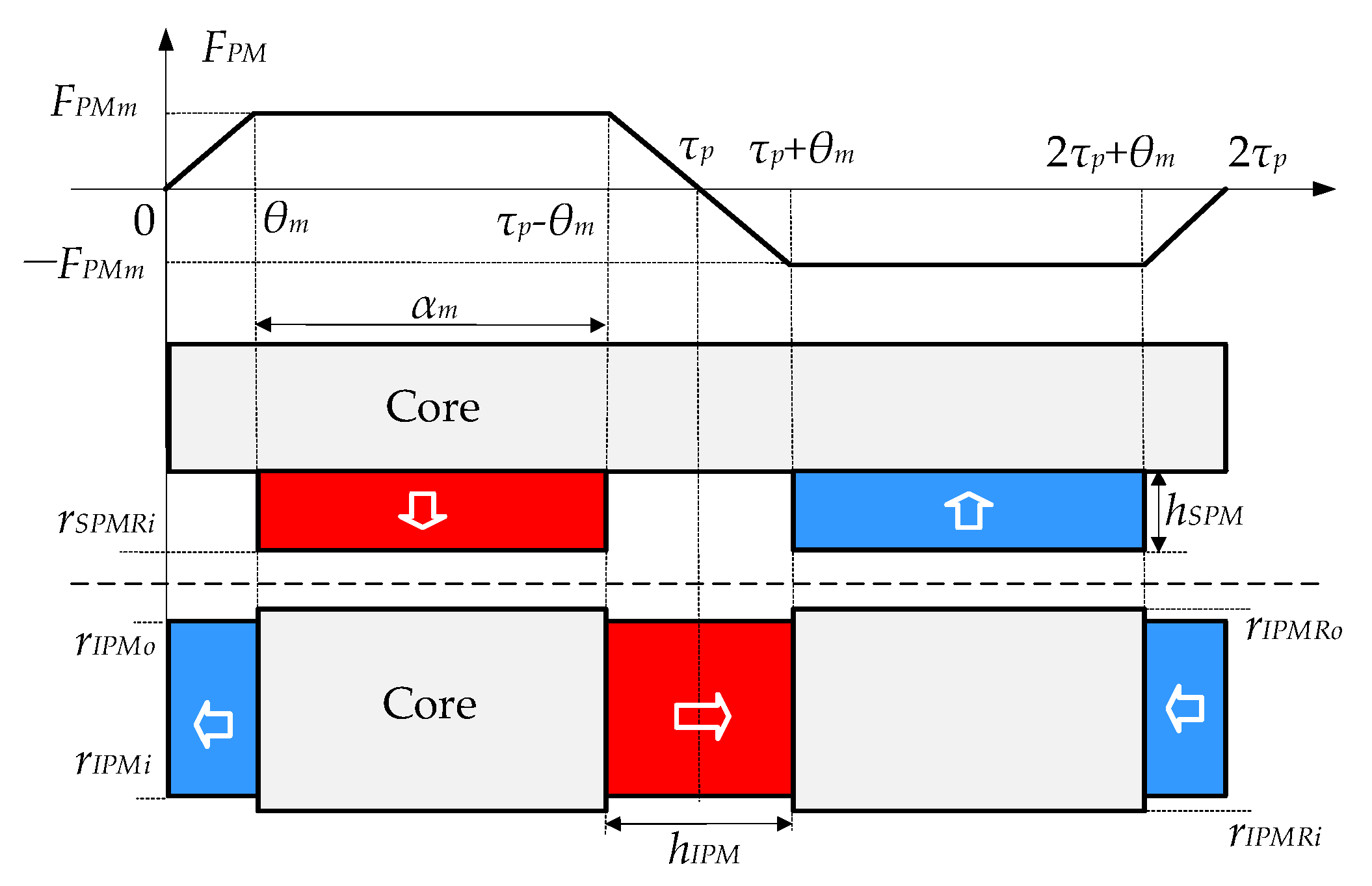
2.1. Modeling of MMF
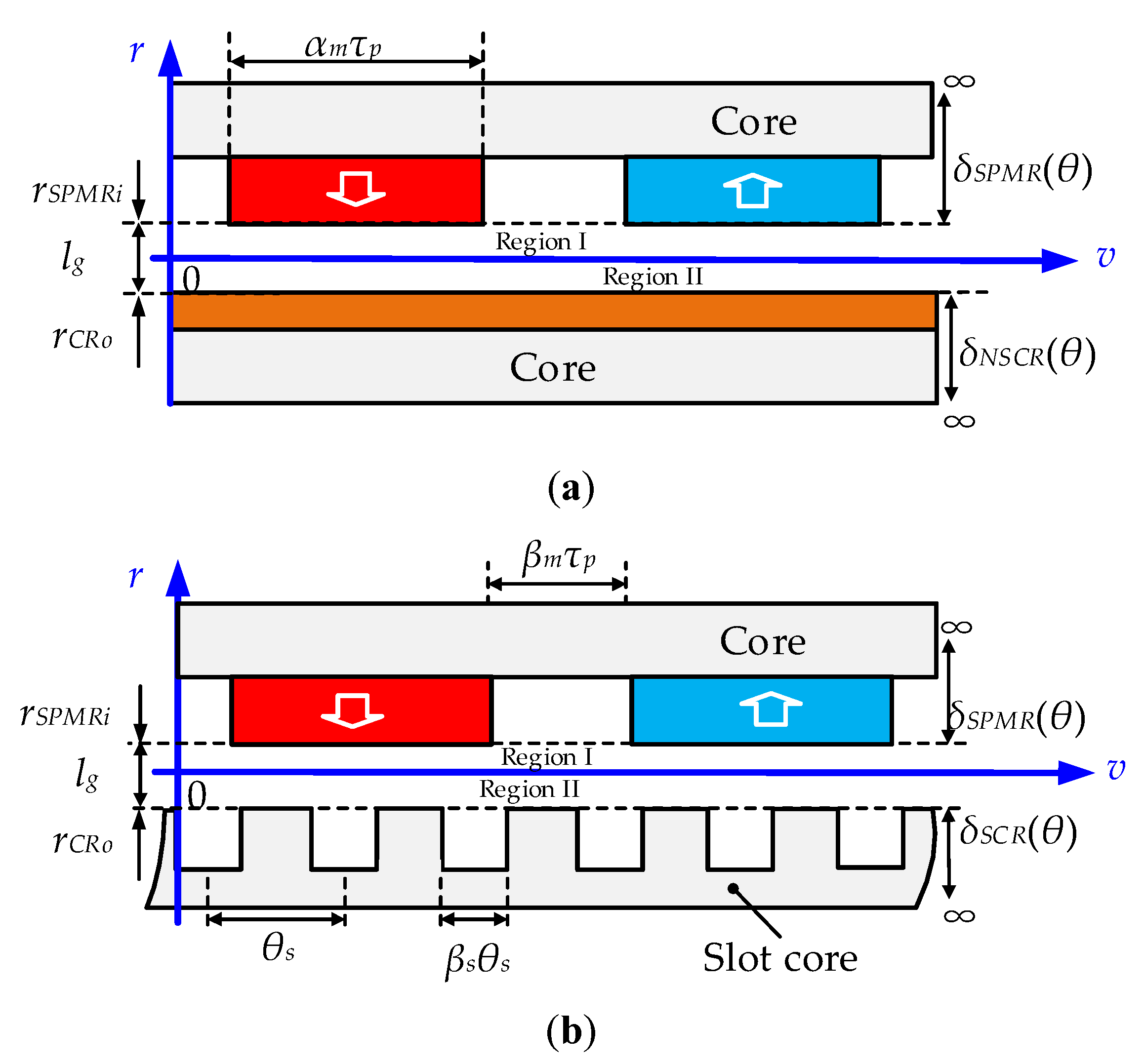
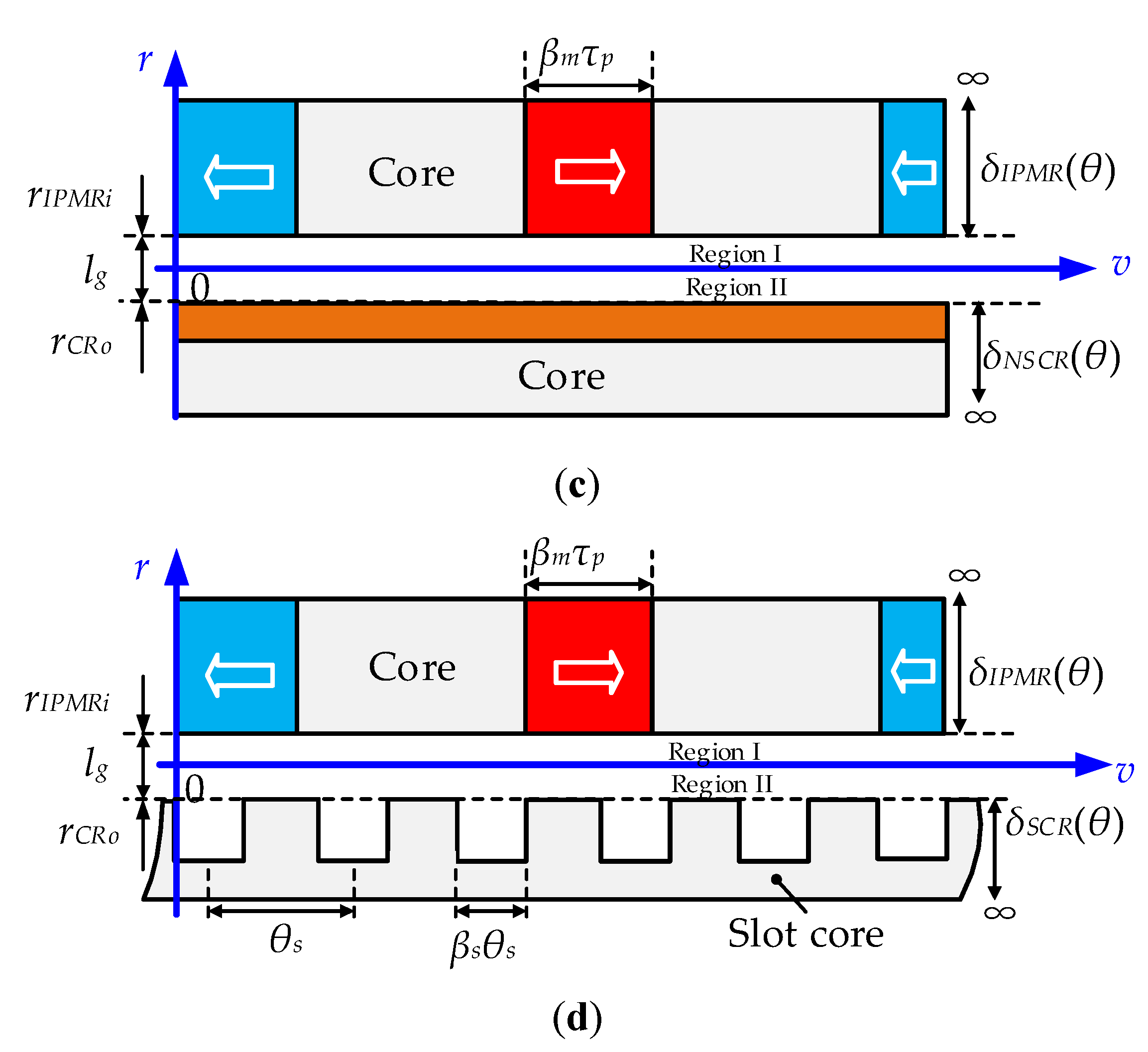
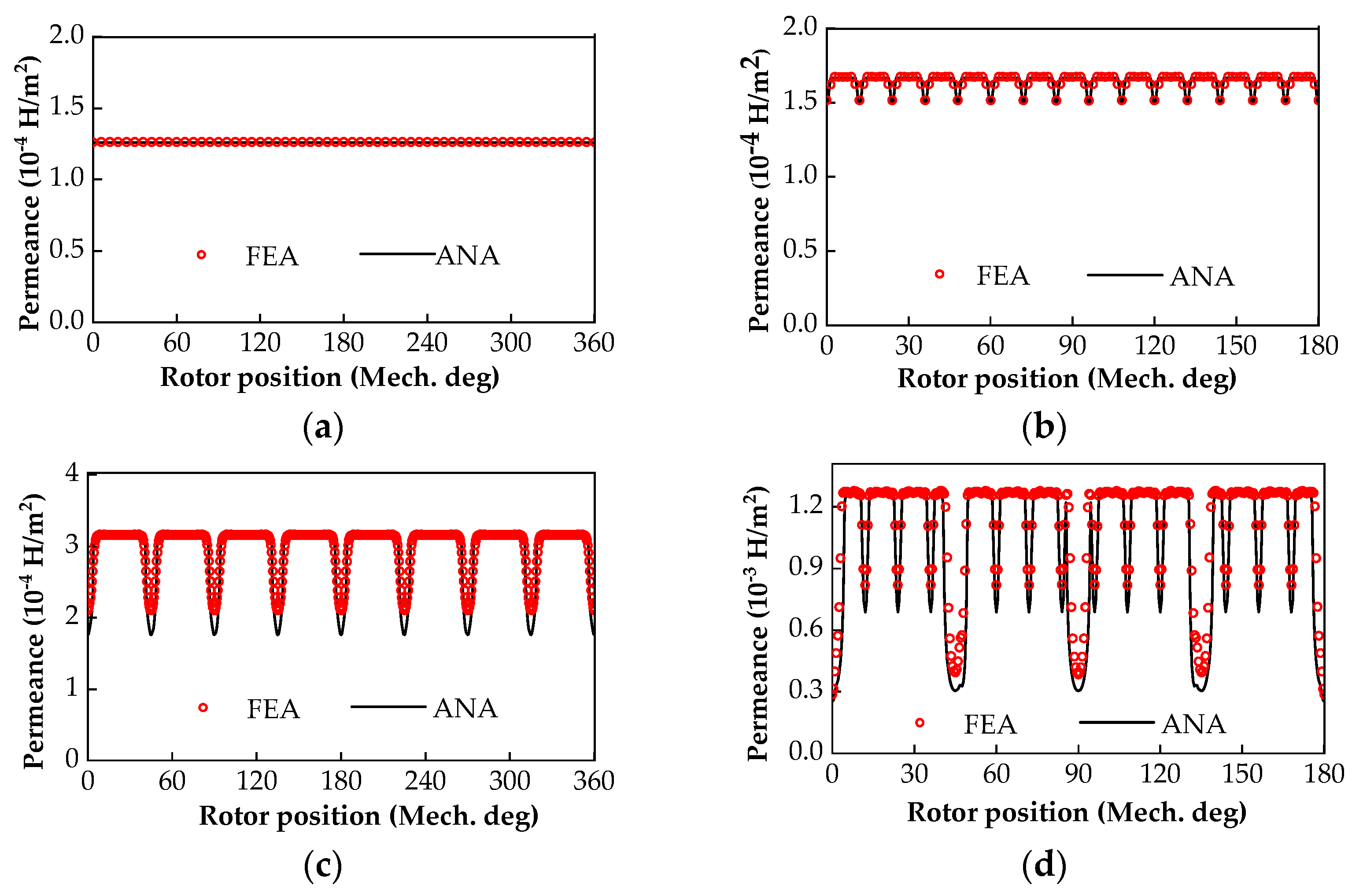
2.2. Air-Gap Permeance Model
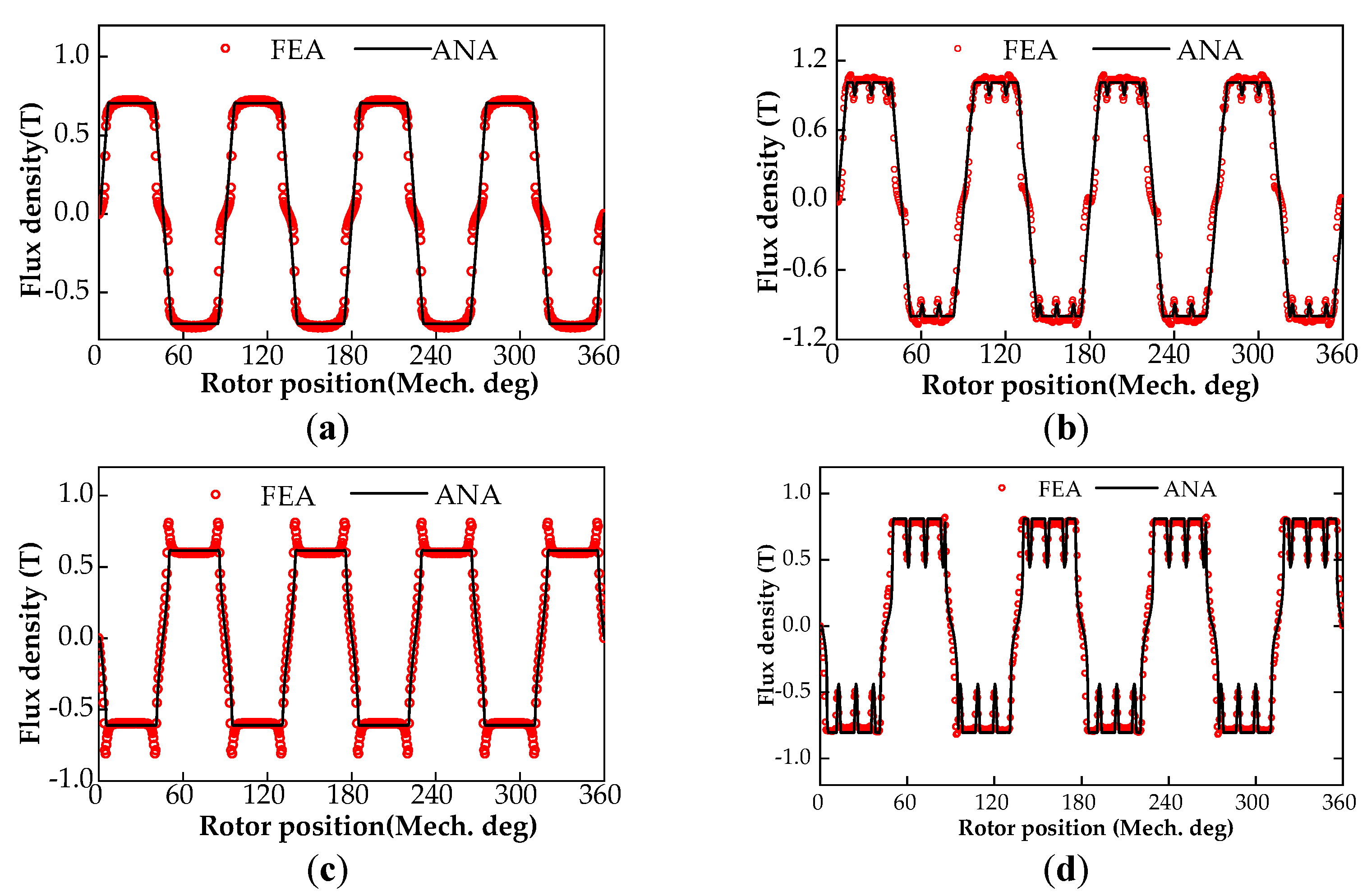
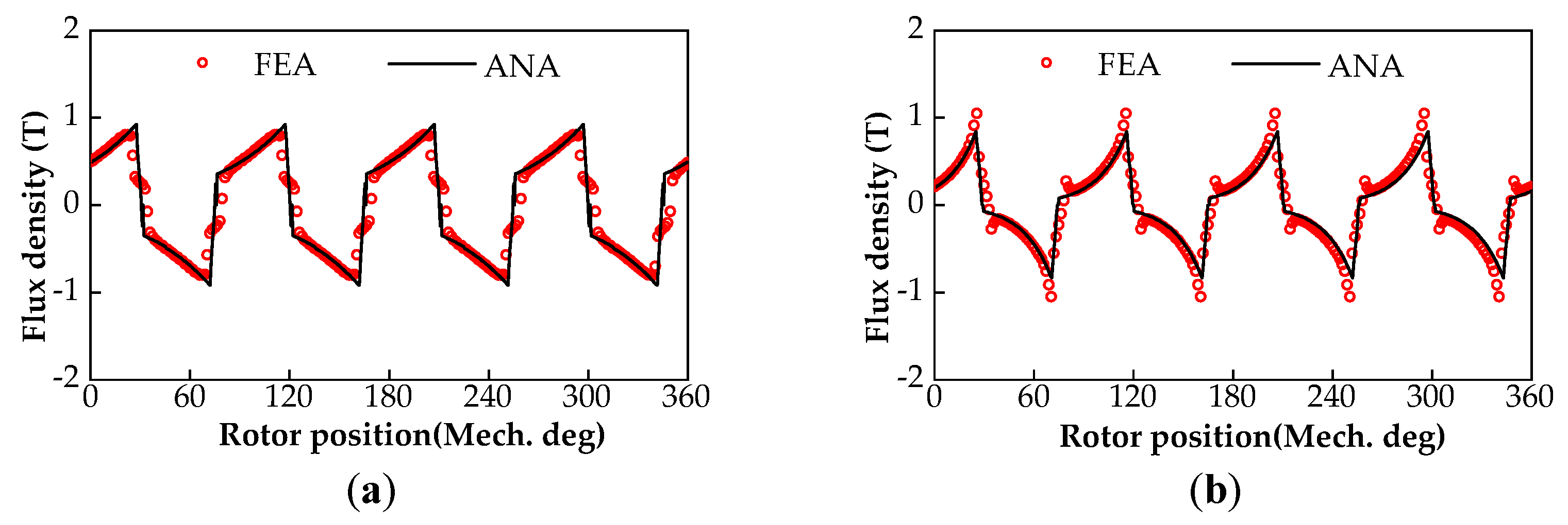
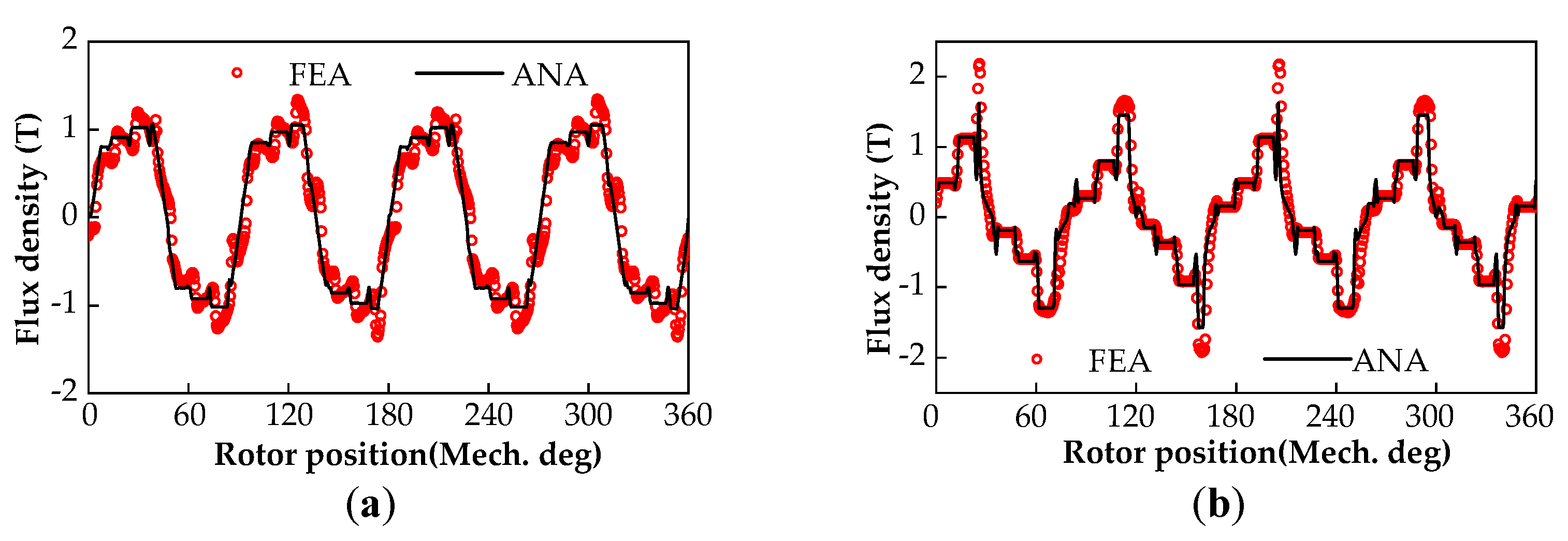
3. Calculation of Air-Gap Magnetic Field
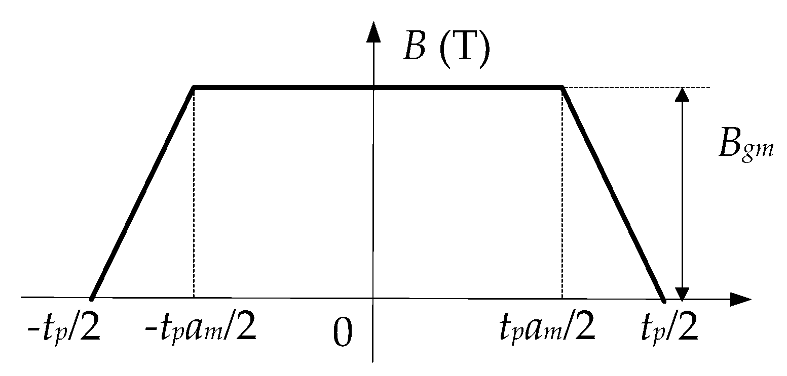
3.1. No-Load Air-Gap Magnetic Field
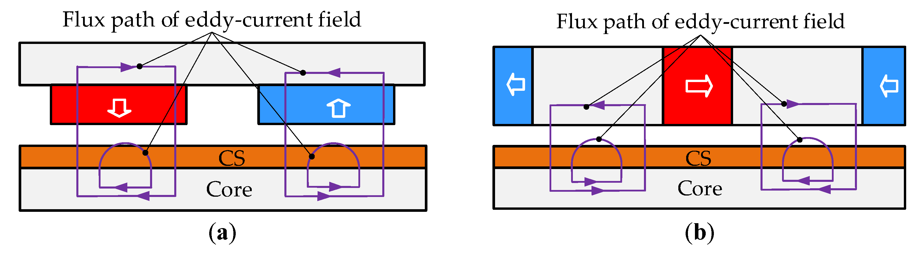
3.2. On-Load Magnetic Field of Non-Slotted Conductor Rotor (CR)
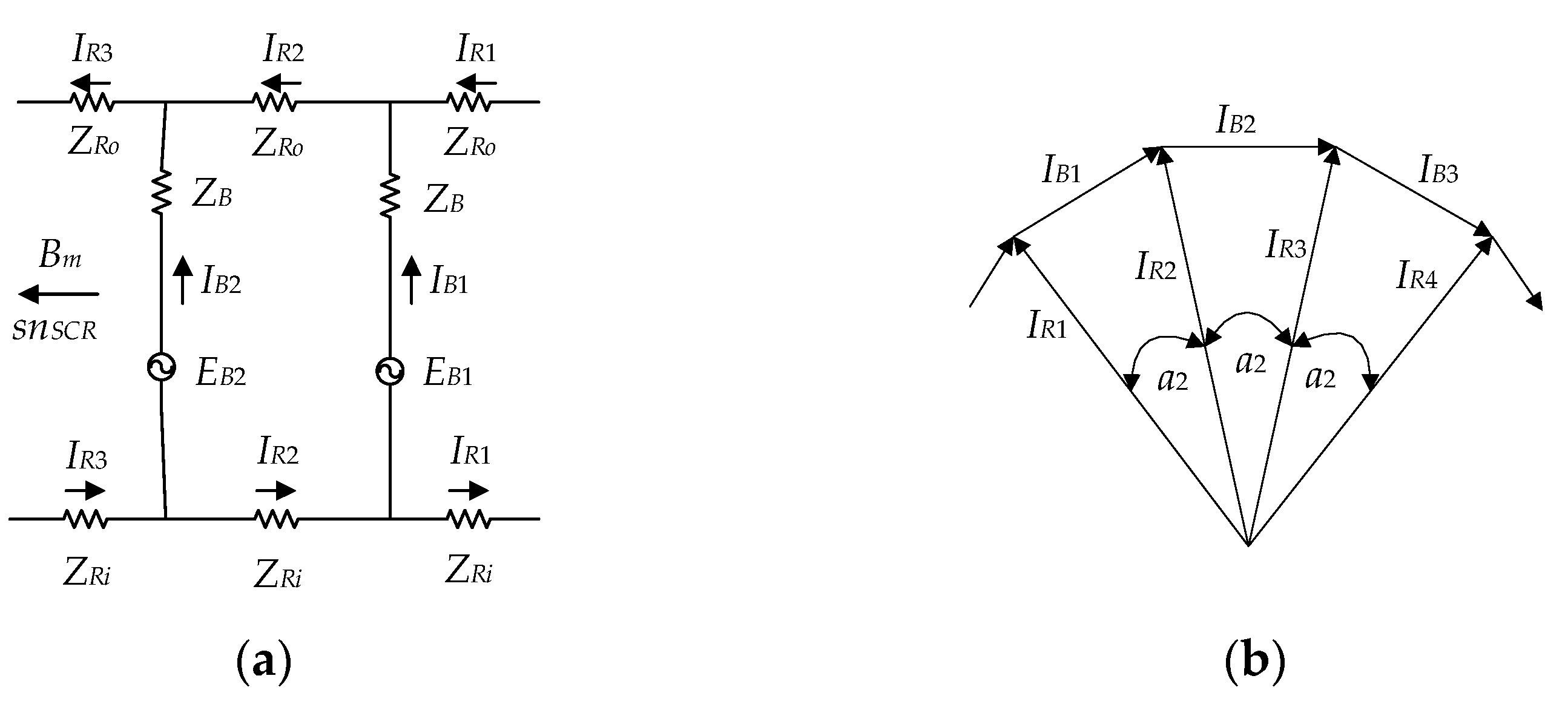
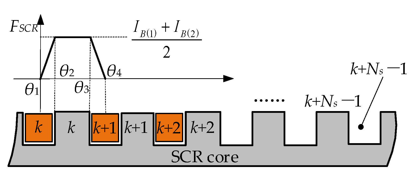
3.3. On-Load Magnetic Field of Slotted CR
4. Electromagnetic and Mechanical Performance
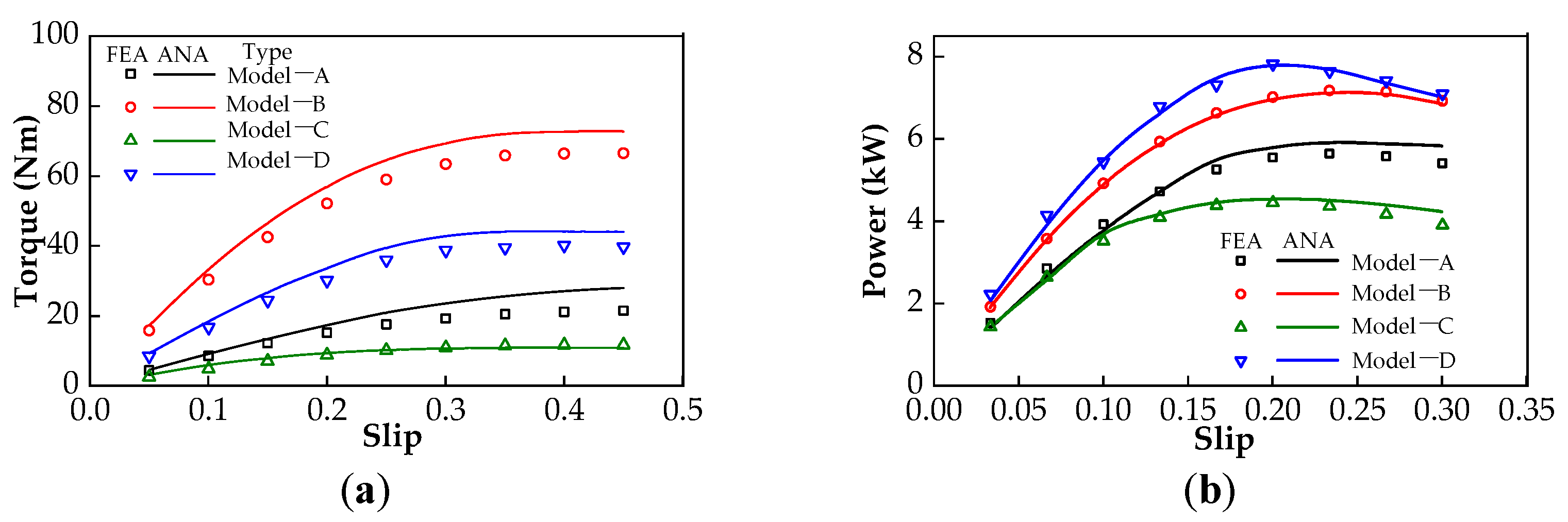
4.1. Power and Torque
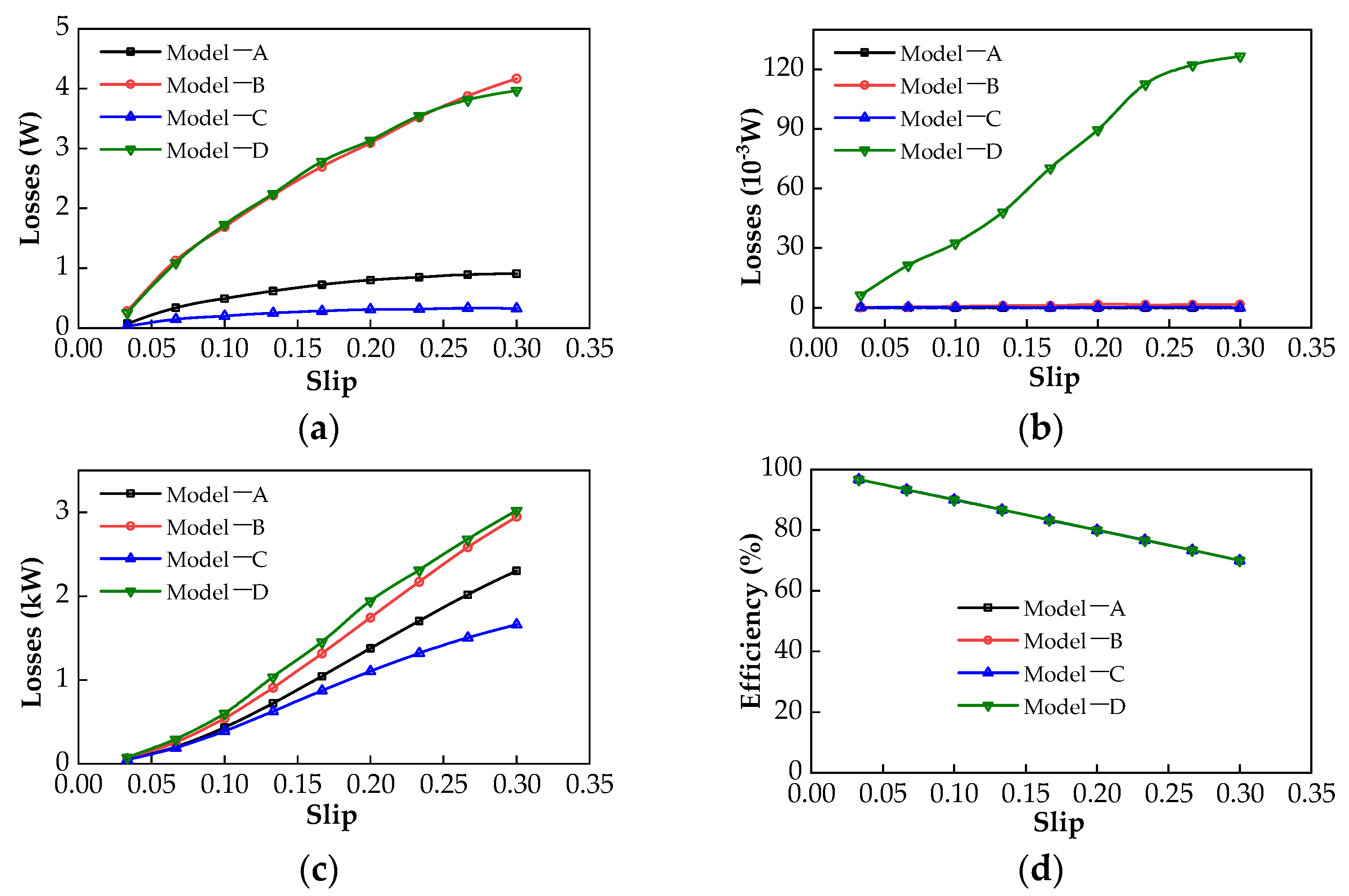
4.2. Loss and Efficiency
5. Conclusions
Author Contributions
Funding
Institutional Review Board Statement
Informed Consent Statement
Data Availability Statement
Acknowledgments
Conflicts of Interest
Nomenclature
| PMECC | permanent magnet eddy current coupler |
| SPM | surface-mounted PM |
| IPM | interior PM |
| PMR | PM rotor |
| CR | conductor rotor |
| SPMR | SPM rotor |
| IPMR | IPM rotor |
| CS | conductor sheet |
| MMF | magnetomotive force |
| EMF | electromotive force |
| EMC | equivalent magnetic circuit |
| FEA | finite element analysis |
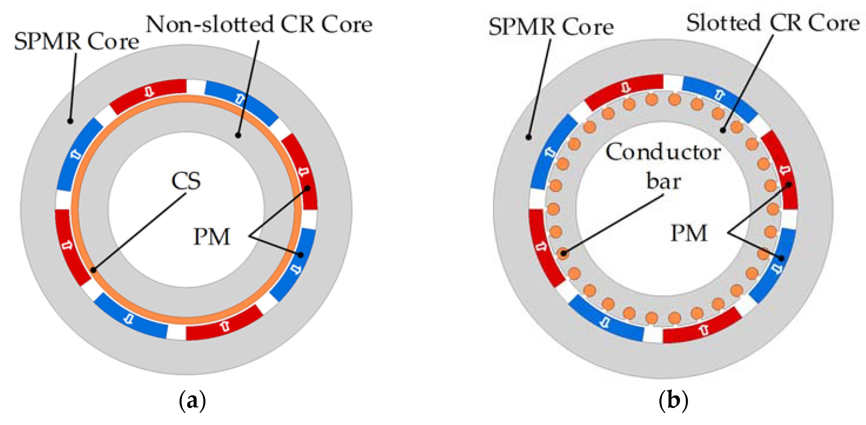
| Model-A | PMECC with SPMR and non-slotted CR |
| Model-B | PMECC with SPMR and slotted CR |
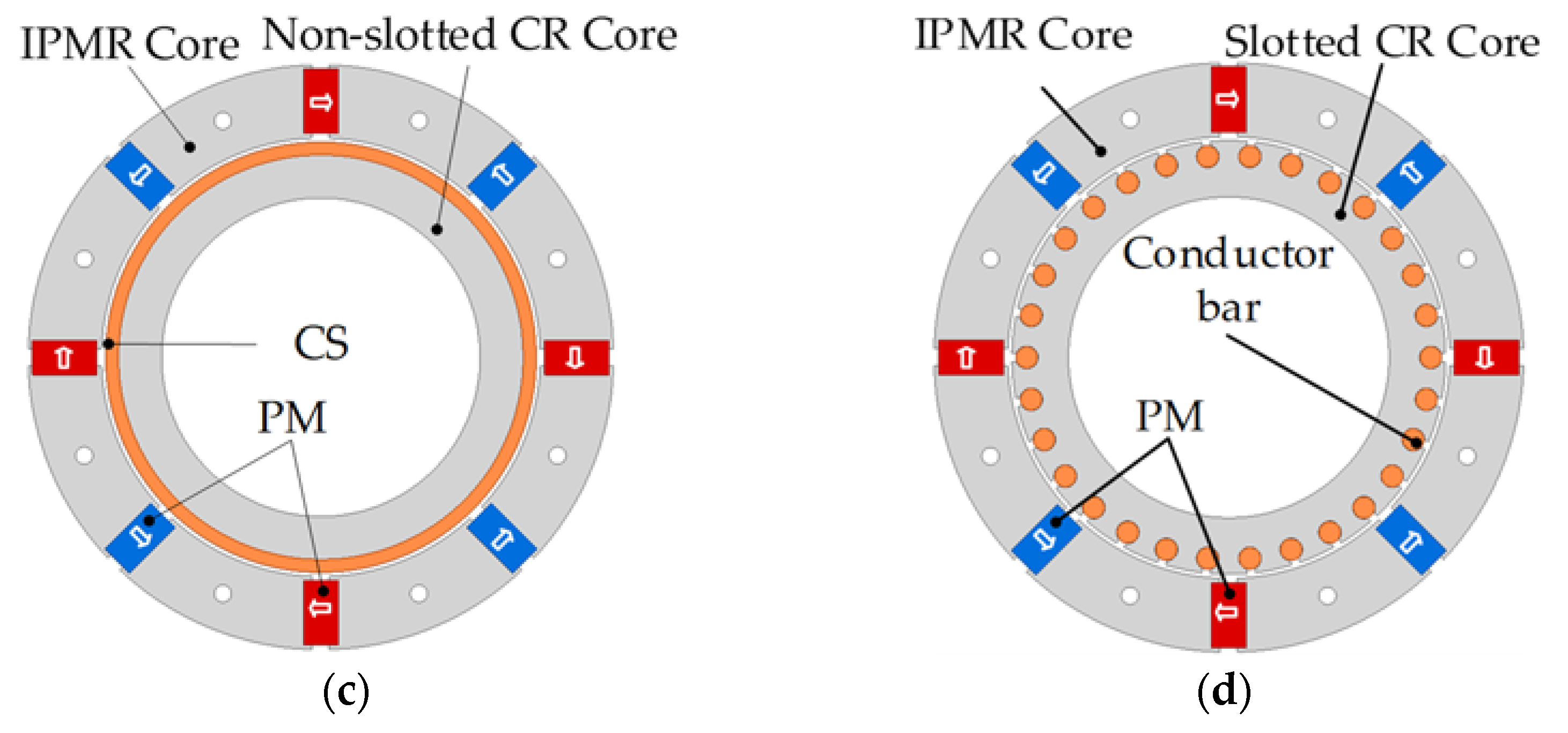
| Model-C | PMECC with IPMR and non-slotted CR |
| Model-D | PMECC with IPMR and slotted CR |
| NS | subscript of parameters relative to Model-A |
| SS | subscript of parameters relative to Model-B |
| NI | subscript of parameters relative to Model-C |
| SI | subscript of parameters relative to Model-D |
| Bg(θ) | air-gap flux density distribution |
| Bgm | amplitude of no-load air-gap flux density |
| Br(θ) | radial component of air-gap flux density |
| FPM(θ) | inner air-gap MMF |
| Λ(θ) | air-gap permeance |
| FPMm | amplitude of FPM(θ) |
| τp | pole pitch of PMR in radian |
| Hc | PM coercivity |
| RCS | reluctance of copper sheet |
| Rg | reluctance of air-gap |
| RSPM | reluctance of SPM |
| RIPM | reluctance of IPM |
| Rend | reluctance of flux leakage at outer radius of IPM |
| hCS | thickness of CS |
| hSPM | thickness of SPM along magnetization direction |
| hIPM | thickness of IPM along magnetization direction |
| lg | length of air-gap |
| L | axial length of PM |
| rIPMo | outer radius of IPM rotor |
| rIPMi | inner radius of IPM rotor |
| rSPMo | outer radius of SPM rotor |
| rSPMi | inner radius of SPM rotor |
| rCSi | inner radius of CS |
| rCSo | outer radius of CS |
| rCRo | outer radius of slotted CR |
| rs | center radius of slot |
| rav | average radius of CS |
| α2 | electrical angle between two adjacent conductor bars |
| Rb | resistance of conductor bar in CR |
| RR | phase resistance of cage end ring, |
| Rb+R | equivalent phase resistance of cage. |
| Xb+R | equivalent phase reactance of slotted structure CR |
| p | number of pole-pairs |
| θm | half of PM width in radian |
| δSPM (θ) | additional air-gap corresponding to equivalent length of SPMR |
| δIPM (θ) | additional air-gap corresponding to equivalent length of IPMR |
| δSCR(θ) | additional air-gap corresponding to equivalent length of slotted CR |
| δNSCR(θ) | additional air-gap corresponding to equivalent length of non-slotted CR |
| φ | phase difference between EMF and current of same conductor bar |
| θs | slot pitch of slotted CR in radian |
| βs | ratio of slot width and slot pitch |
| k,n | positive integer |
| Ωin | input speed of PMECC (rad/s) |
| Ωout | output speed of PMECC (rad/s) |
| Ωs | slip speed (rad/s) |
| wm | radial length of IPM |
| Br | PM remanence |
| μr | relative permeance of PM |
| Ns | slot numbers of slotted CR |
| σ | copper conductivity (75 °C) |
| μ0 | vacuum permeability (4π×10−7 H/m) |
| αm | pole-arc coefficient of PMR |
| Cfe | iron consumption coefficient |
| B | magnetic density of iron core |
| G | quality of rotor iron core |
| IB | effective phase current of conductor bar |
| IR | effective phase current of end ring |
Appendix A

| Structural Parameters | Model-A | Model-B | Model-C | Model-D |
|---|---|---|---|---|
| rCRo | 50 mm | 50 mm | 50 mm | 50 mm |
| hCS | 3 mm | -- | 3 mm | -- |
| σ | 5.77 × 10⁷ S/m | 5.77 × 10⁷ S/m | 5.77 × 10⁷ S/m | 5.77 × 10⁷ S/m |
| loh | 5 mm | -- | 5 mm | -- |
| hCRc | 10 mm | 20 mm | 10 mm | 20 mm |
| hSPMRc | 10 mm | 10 mm | -- | -- |
| hIPMRc | -- | -- | 27.5 mm | 27.5 mm |
| lg | 1 mm | 1 mm | 1 mm | 1 mm |
| rPMRi | 51 mm | 51 mm | 51 mm | 51 mm |
| hSPM | 6 mm | 6 mm | -- | -- |
| hIPM | -- | -- | 8 mm | 8 mm |
| SPM | 203.6 mm2 | 203.6 mm2 | 203.6 mm2 | 203.6 mm2 |
| L | 50 mm | 50 mm | 50 mm | 50 mm |
| Hc | −890 kA/m | −890 kA/m | −890 kA/m | −890 kA/m |
| p | 4 | 4 | 4 | 4 |
| αm | 0.80 | 0.80 | 0.80 | 0.80 |
| rslot | -- | 2.5 mm | -- | 2.5 mm |
| Ns | -- | 30 | -- | 30 |
References
- Davies, E. An Experimental and Theoretical Study of Eddy-Current Couplings and Brakes. IEEE Trans. Power Appar. Syst. 1963, 82, 401–419. [Google Scholar] [CrossRef]
- Canova, A.; Vusini, B. Design of axial eddy-current couplers. IEEE Trans. Ind. Appl. 2003, 39, 725–733. [Google Scholar] [CrossRef]
- Lubin, T.; Rezzoug, A. Steady-State and Transient Performance of Axial-Field Eddy-Current Coupling. IEEE Trans. Ind. Electron. 2014, 62, 2287–2296. [Google Scholar] [CrossRef] [Green Version]
- Sharif, S.; Faiz, J.; Sharif, K. Performance analysis of a cylindrical eddy current brake. IET Electr. Power Appl. 2012, 6, 661–668. [Google Scholar] [CrossRef]
- Yazdanpanah, R.; Mirsalim, M. Axial-flux wound-excitation eddy current brakes: Analytical study and parametric modeling. IEEE Trans. Magn. 2014, 50, 1–10. [Google Scholar] [CrossRef]
- Mohammadi, S.; Mirsalim, M.; Vaez-Zadeh, S.; Talebi, H.A. Analytical Modeling and Analysis of Axial-Flux Interior Permanent-Magnet Couplers. IEEE Trans. Ind. Electron. 2014, 61, 5940–5947. [Google Scholar] [CrossRef]
- Dai, X.; Liang, Q.; Cao, J.; Long, Y.; Mo, J.; Wang, S. Analytical Modeling of Axial-Flux Permanent Magnet Eddy Current Couplings with a Slotted Conductor Topology. IEEE Trans. Magn. 2015, 52, 1–15. [Google Scholar] [CrossRef]
- Canova, A.; Freschi, F.; Gruosso, G.; Vusini, B. Genetic optimisation of radial eddy current couplings. COMPEL Int. J. Comput. Math. Electr. Electron. Eng. 2005, 24, 767–783. [Google Scholar] [CrossRef]
- Lubin, T.; Rezzoug, A. Improved 3-D Analytical Model for Axial-Flux Eddy-Current Couplings with Curvature Effects. IEEE Trans. Magn. 2017, 53, 1–9. [Google Scholar] [CrossRef]
- Mohammadi, S.; Mirsalim, M.; Vaez-Zadeh, S. Nonlinear Modeling of Eddy-Current Couplers. IEEE Trans. Energy Convers. 2013, 29, 224–231. [Google Scholar] [CrossRef]
- Mohammadi, S.; Mirsalim, M. Double-sided permanent-magnet radial-flux eddy current couplers: Three-dimensional analytical modelling, static and transient study, and sensitivity analysis. IET Electr. Power Appl. 2013, 7, 665–679. [Google Scholar] [CrossRef]
- Mohammadi, S.; Mirsalim, M.; Niazazari, M.; Talebi, H.A. A new interior permanent-magnet radial-flux eddy-current coupler. In Proceedings of the 5th Annual International Power Electronics, Drive Systems and Technologies Conference (PEDSTC 2014), Tehran, Iran, 5–6 February 2014; pp. 500–505. [Google Scholar] [CrossRef]
- Wang, J.; Lin, H.; Fang, S.; Huang, Y. A General Analytical Model of Permanent Magnet Eddy Current Couplings. IEEE Trans. Magn. 2013, 50, 1–9. [Google Scholar] [CrossRef]
- Zhang, H.; Wang, D.; Wang, X.; Wang, X. Equivalent Circuit Model of Eddy Current Device. IEEE Trans. Magn. 2018, 54, 1–9. [Google Scholar] [CrossRef]
- Wang, J.; Zhu, J. A Simple Method for Performance Prediction of Permanent Magnet Eddy Current Couplings Using a New Magnetic Equivalent Circuit Model. IEEE Trans. Ind. Electron. 2017, 65, 2487–2495. [Google Scholar] [CrossRef]
- Li, Y.; Lin, H.; Yang, H. A novel squirrel-cage rotor permanent magnet adjustable speed drive with a non-rotary mechanical flux adjuster. IEEE Trans. Energy Convers 2021, 36, 1036–1044. [Google Scholar] [CrossRef]
- Yang, X.; Liu, Y.; Wang, L. Nonlinear Modeling of Transmission Performance for Permanent Magnet Eddy Current Coupler. Math. Probl. Eng. 2019, 2019, 1–14. [Google Scholar] [CrossRef]
- Gaussens, B.; Hoang, E.; de la Barriere, O.; Saint-Michel, J.; Lecrivain, M.; Gabsi, M. Analytical approach for air-gap modeling of field-excited flux-switching machine: No-load operation. IEEE Trans. Magn. 2012, 48, 2505–2517. [Google Scholar] [CrossRef] [Green Version]
- Gaussens, B.; Hoang, E.; de la Barriere, O.; Saint-Michel, J.; Manfe, P.; Lécrivain, M.; Gabsi, M. Analytical armature reaction field prediction in field-excited flux-switching machines using an exact relative permeance function. IEEE Trans. Magn. 2013, 49, 628–641. [Google Scholar] [CrossRef]
- Gibbs, W.J. Conformal Transformations in Electrical Engineering; Chapman & Hall: London, UK, 1958. [Google Scholar]
- Zarko, D.; Ban, D.; Lipo, T.A. Analytical calculation of magnetic field distribution in the slotted air-gap of a surface permanent-magnet motor using complex relative air-gap permeance. IEEE Trans. Magn. 2006, 42, 1828–1837. [Google Scholar] [CrossRef]
- Žarko, D.; Ban, D.; Lipo, T.A. Analytical Solution for Cogging Torque in Surface Permanent-Magnet Motors Using Conformal Mapping. IEEE Trans. Magn. 2007, 44, 52–65. [Google Scholar] [CrossRef]
- Hamata, V.; Heller, B. Harmonic Field Effects in Induction Machines; Elsevier: Amsterdam, The Netherlands, 1977. [Google Scholar]
- Zhu, Z.; Howe, D. Instantaneous magnetic field distribution in brushless permanent magnet DC motors. III. Effect of stator slotting. IEEE Trans. Magn. 1993, 29, 143–151. [Google Scholar] [CrossRef]
- Li, Y.; Lin, H.; Tao, Q.; Lu, X.; Yang, H.; Fang, S.; Wang, H. Analytical analysis of an adjustable-speed permanent magnet eddy-current coupling with a non-rotary mechanical flux adjuster. IEEE Trans. Magn. 2019, 55, 1–5. [Google Scholar] [CrossRef]
- Russell, R.L.; Norsworthy, K.H. Eddy currents and wall losses in screened-rotor induction motors. Proc. IEE-Part A Power Eng. 1958, 105, 163–175. [Google Scholar] [CrossRef]


Publisher’s Note: MDPI stays neutral with regard to jurisdictional claims in published maps and institutional affiliations. |
© 2021 by the authors. Licensee MDPI, Basel, Switzerland. This article is an open access article distributed under the terms and conditions of the Creative Commons Attribution (CC BY) license (https://creativecommons.org/licenses/by/4.0/).
Share and Cite
Li, Y.; Huang, J.; Gao, F.; Zhu, Z.; Han, Y.; Li, Y.; Sun, Q.; Zhang, D. The Analytical Comparative Analysis of Electromagnetic Characteristics of Four Typical Radial Flux Permanent Magnet Eddy Current Couplers. Energies 2021, 14, 8407. https://doi.org/10.3390/en14248407
Li Y, Huang J, Gao F, Zhu Z, Han Y, Li Y, Sun Q, Zhang D. The Analytical Comparative Analysis of Electromagnetic Characteristics of Four Typical Radial Flux Permanent Magnet Eddy Current Couplers. Energies. 2021; 14(24):8407. https://doi.org/10.3390/en14248407
Chicago/Turabian StyleLi, Yibo, Jiacai Huang, Fangzheng Gao, Zhiying Zhu, Yufei Han, Yao Li, Quan Sun, and Duo Zhang. 2021. "The Analytical Comparative Analysis of Electromagnetic Characteristics of Four Typical Radial Flux Permanent Magnet Eddy Current Couplers" Energies 14, no. 24: 8407. https://doi.org/10.3390/en14248407
APA StyleLi, Y., Huang, J., Gao, F., Zhu, Z., Han, Y., Li, Y., Sun, Q., & Zhang, D. (2021). The Analytical Comparative Analysis of Electromagnetic Characteristics of Four Typical Radial Flux Permanent Magnet Eddy Current Couplers. Energies, 14(24), 8407. https://doi.org/10.3390/en14248407