
Commercial Aircraft Electrification—Current State and Future Scope


Abstract
:1. Introduction
2. Evolution of More Electric Aircraft
2.1. More Electric Aircraft
- Better reliability;
- Improved volume and weight of subsystems;
- Improvement in the system power efficiency;
- Better maintainability;
- Rapid and cost-effective insertion of technology;
- System level optimisation and new capabilities.
2.2. Aircraft Electrical Power Systems
- (a)
- Architecture and interconnect: propulsion, insulation, connectors, whole aircraft and protection.
- (b)
- Electrical energy storage: energy storage, energy management, energy generation and infrastructure.
- (c)
- Electrical machines: motors, generators, transformers, actuators and drivers.
- (d)
- Power electronics: power conversion, switching, monitoring and control [2].
2.3. Aircraft Components That Are Electrified
3. Propulsion
3.1. Requirements/Barriers of Electrically Propelled Aircraft
- Battery performance—Reduced weight and good battery storage capacity are vital for hybrid and all-electric aircraft architectures. If batteries are not designed to be lightweight, the aviation industry will be forced to discontinue the use of batteries in their system. Currently the highest commercial battery energy storage has energy density range from 150 to 250 Wh/kg; however, an ideal energy density in these batteries would be at least 500 Wh/kg. In addition, to improve energy density, long battery life-cycles and better recharging speeds are also essential for battery-powered aircraft [10].
- Battery safety—Effective hazard containment systems for batteries to meet airworthiness and safety of public concerns are vital in aircraft systems.
- Power density—High power density, light and efficient motors and generators are essential for configuration that requires multiple distributed fans to obtain high-power propulsive efficiency. Hybrid/turbo-electric architectures will also require these types of generators/motors to convert the shaft power to electricity, in conjunction with lightweight gearbox to reduce the rotational speed of the turbine to a much slower rate suitable for the generator.
- Power electronics—To convert, switch and condition the power whilst maintaining minimum electrical and heat losses.
3.2. Recent Developments in Electric Aircraft
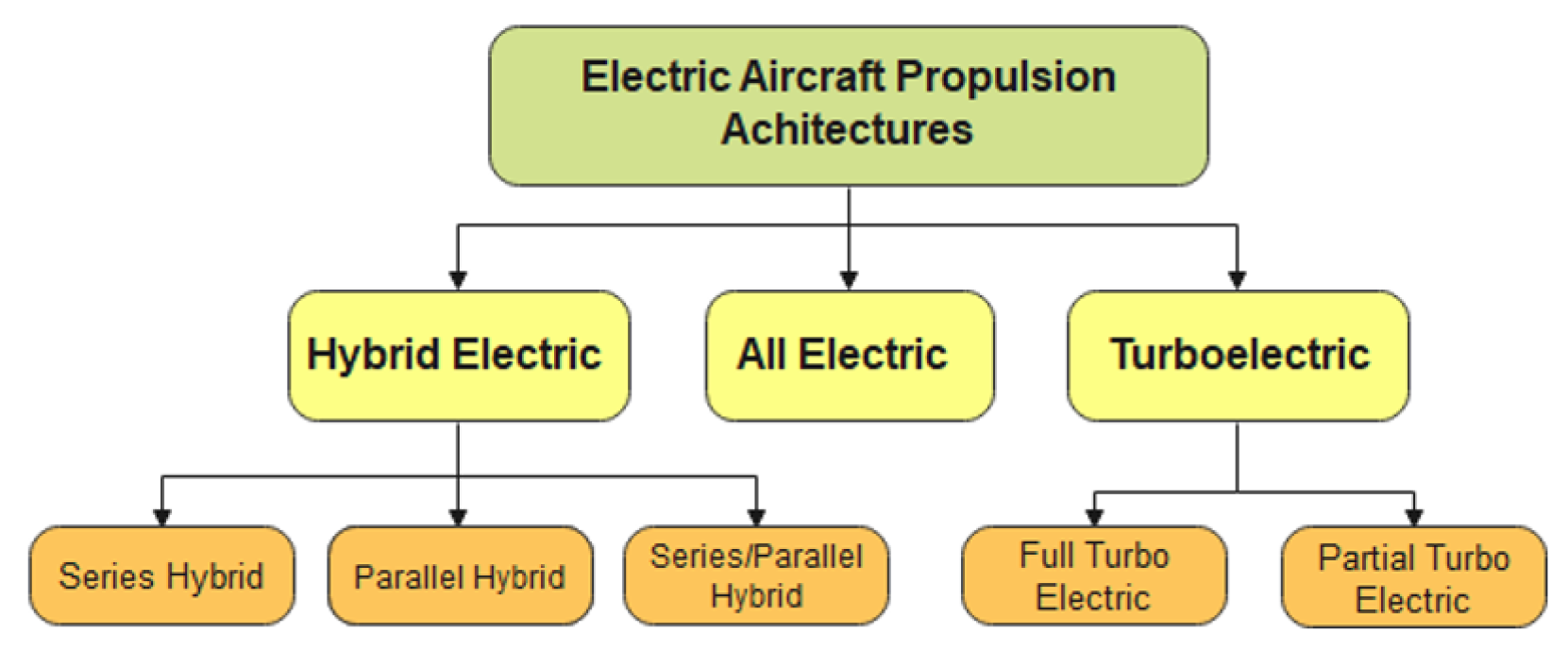
3.3. Electric Aircraft Propulsion Architectures
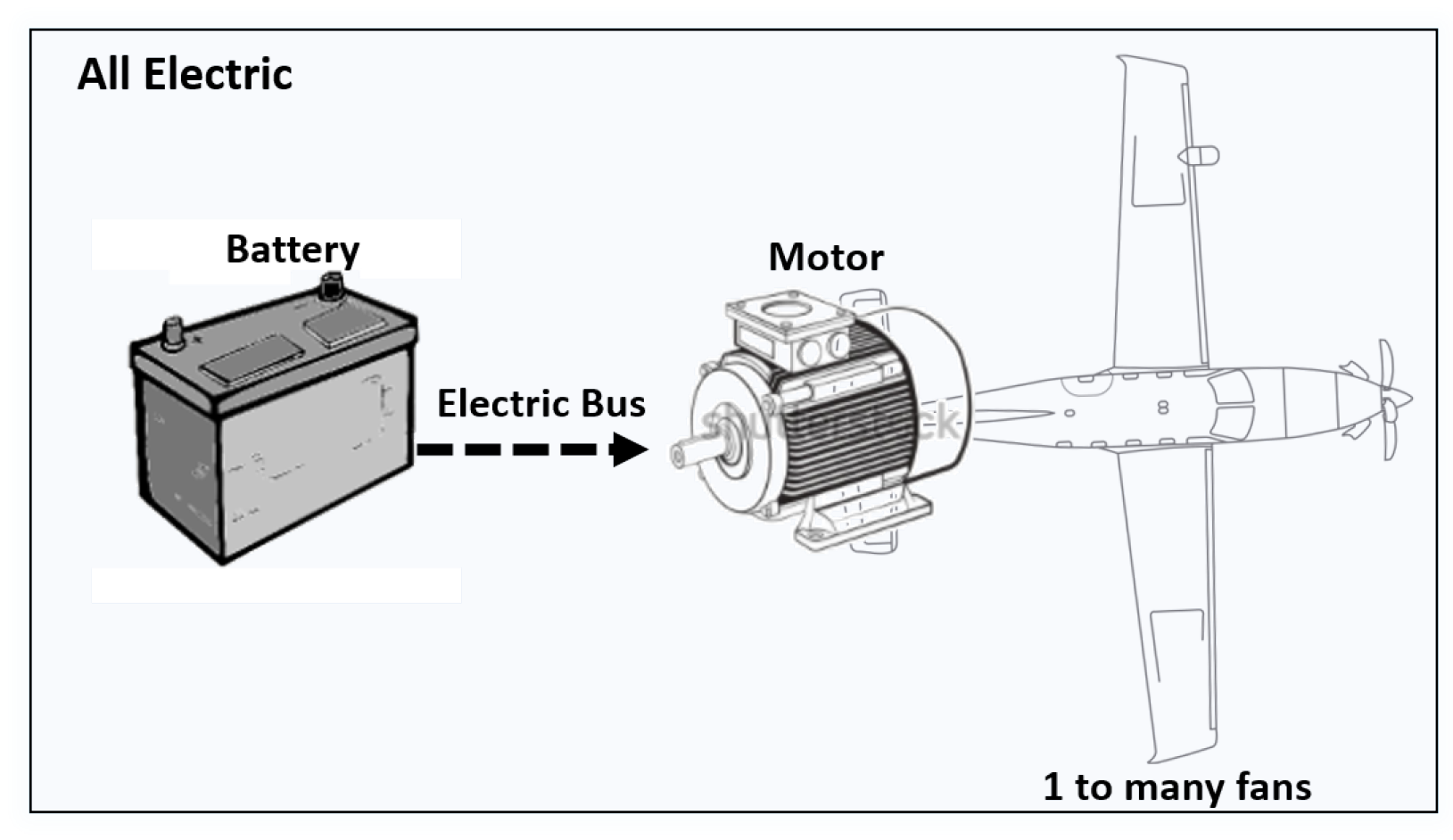
- All electric: Aircraft with small seats are feasible in the near future but for the development of a fully electric passenger aircraft, drastic improvements in drivetrains are required. All electric architecture uses the energy stored in the battery to drive one or multiple fans. This system will be heavily dependent on the weight and storage capacity of the battery [1]. Battery sources are the only source of propulsion power on battery-powered fully electric aircraft [11]. An example of a fully electric aircraft is the Airbus E-fan which was a two-seater electric flight launched in 2014 [13]. Fully electric propulsion architecture can be observed in Figure 5. As displayed in the diagram electric motor and battery forms the two main components in this system.
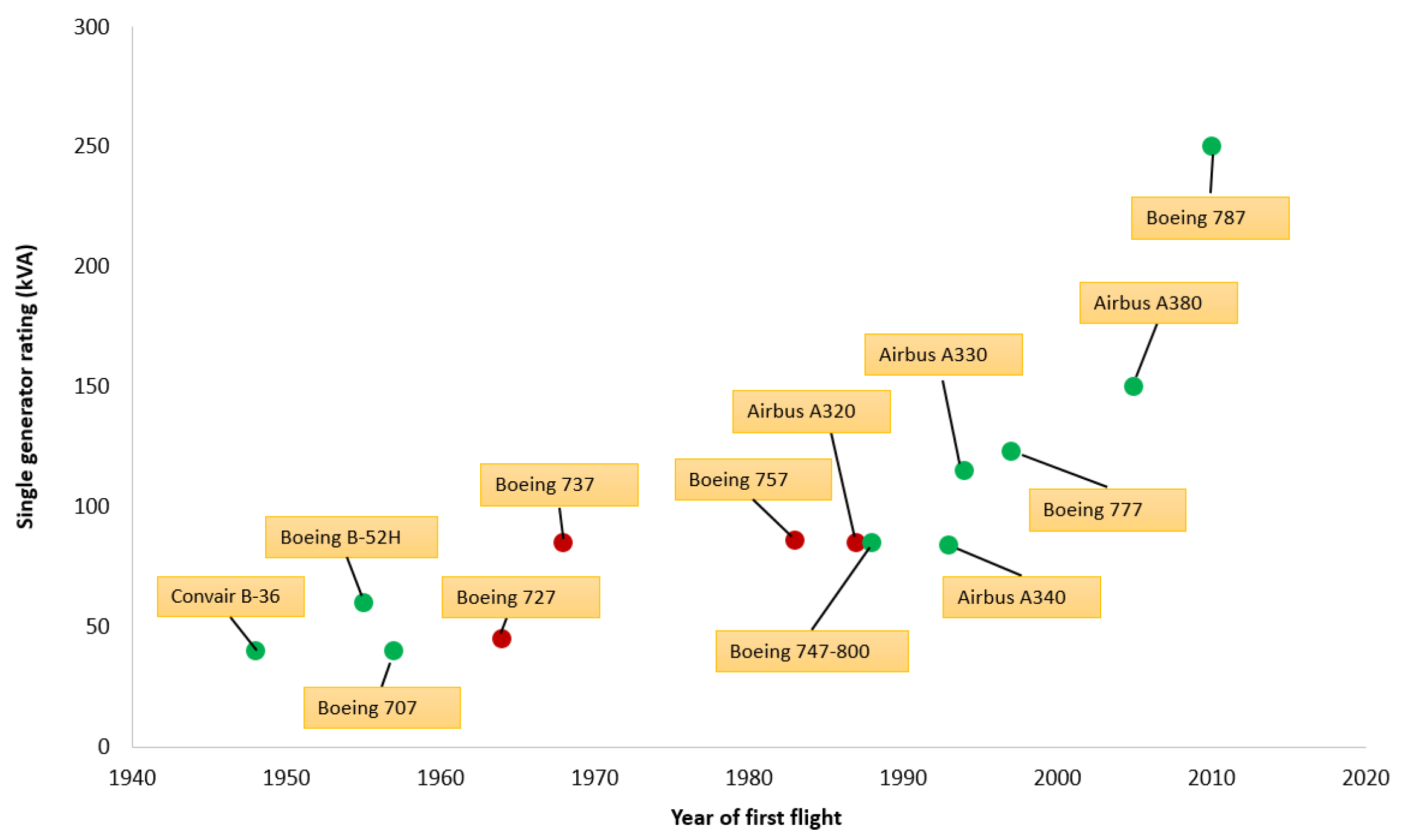
- Hybrid electric: Hybrid-electric large aircraft concepts are proposed from mid-2030 based on the integration of traditional turbo engine into the propulsion system. Various level of hybridisation can be achieved and the degree of hybridisation (H) with respect to power and energy can be defined using Equation (1), where is the electric motor power and is the battery energy. The parameters and will be 0 on a non-electric aircraft and 1 in all-electric configurations. In turbo electric architectures, is 0 as they do not carry stored energy while hybrid architecture have them greater than 0 [14].In hybrid-electric propulsion systems, electrical power is produced using generators. These generator systems are bigger than motor systems due to the massive demand for larger-power electronics, to generate electrical power and torque. Some aircraft such as the Boeing 787 uses multiple smaller generators rather than one large generator to increase the flight-critical system’s power system reliability [11]. More details on the configuration can be found in [14].
- Parallel hybrid: A battery-powered motor and a turbine engine is mounted on the shaft to drive the fan so that either of those can provide propulsion when required. As the internal combustion engine and the electric motor is mechanically connected to the propeller, they can contribute to the propulsion energy individually or simultaneously. It also has the advantage of only having two propulsion devices in comparison to series configuration making the overall system smaller and still achieve the same performance. However, the propeller’s rotational speed is not always at the optimal speed of the engine; therefore, operation at engine’s optimum region cannot be guaranteed. An example of parallel hybrid system can be seen in the SUGAR Volt’s Subsonic Ultra Green Aircraft Research [9,11,15,16,17,18].
- Series hybrid: The benefit of series hybrid configuration is that the output power is not related to the power demand of the power train and the engine is fully decoupled from the propeller. Therefore, the engine can work at its optimal operating conditions even at different working environments. The lifespan of the engine can be lengthened and the fuel efficiency of the engine will remain high for this configuration. It also has major advantage of having the flexibility of locating the ICE-generator set due to mechanical decoupling. As there is a large power loss in the combustion and energy conversion, series hybrid architecture suffers from power system efficiency. Another drawback of this configuration is the need of three propulsion devices namely, generator, motor and engine making it more expensive and bulky. It also cannot make use of the engine and motor’s maximum combined potential power as it is not mechanically connected to the load.
- Series/parallel hybrid: This configuration is a mixture of series and parallel configurations. The structure of this architecture makes the power distribution very flexible whilst allowing the motor and engine to operate in the optimum region. Series architecture requires the most complex gearing or clutch mechanism and energy management but it is the most advanced hybrid propulsion system available.Overall, the series-parallel is the most complex configuration amongst the three hybrid options; however, series configuration enables the engine to operate at its best operating condition [11,19,20]. Overview of the hybrid architectures can be observed in Figure 6. The components displayed in the diagram is an approximate representation of electrical machine images, it is much more advanced in reality.
- Turbo electric—The turbo electric concepts are largely dependent on electrical power system technology advances. These technologies include: power electronics for converting; conditioning and distributing power; generator systems for electrical power generation; energy storage motors and high power aircraft distribution system for circuit protection. Full or partial turbo electric configurations are not reliant on batteries at any phase of the flight for propulsion energy. It has the advantage of gaining a higher propulsive efficiency as it provides the designer more freedom with the location and number of propulsive fans. An example of a turbo electric development can be seen in distributed open rotor aircraft concept by Rolls-Royce for regional aircraft.
- Full turbo electric: It uses gas turbine to drive the generator which powers the electric motors that drive the fans.
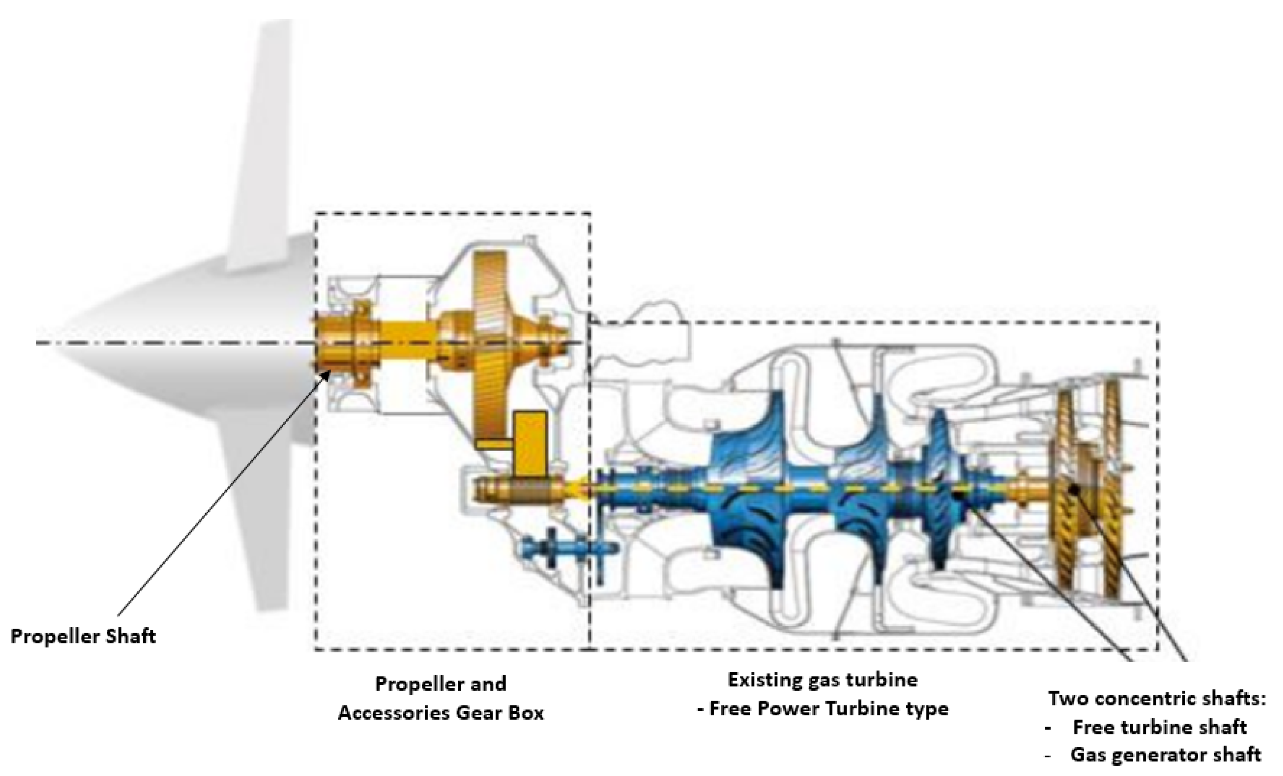
- Partial turbo electric: This system is an alternative to the full turbo electric configuration, where it uses the electric propulsion to provide part of the propulsive power and the rest are provided by a turbofan which is driven using a gas turbine. The NASA STARC-ABL is an example of a partial turbo electric system. This architecture or some other variant of turbo electric system are likely to be the first options for electric propulsion systems in regional or single-aisle aircraft configurations. It is also likely to be first application that can make a significant impact in aviation carbon emission [9,11,14,15]. An overview of a labelled turbo electric architecture can be seen in Figure 7.

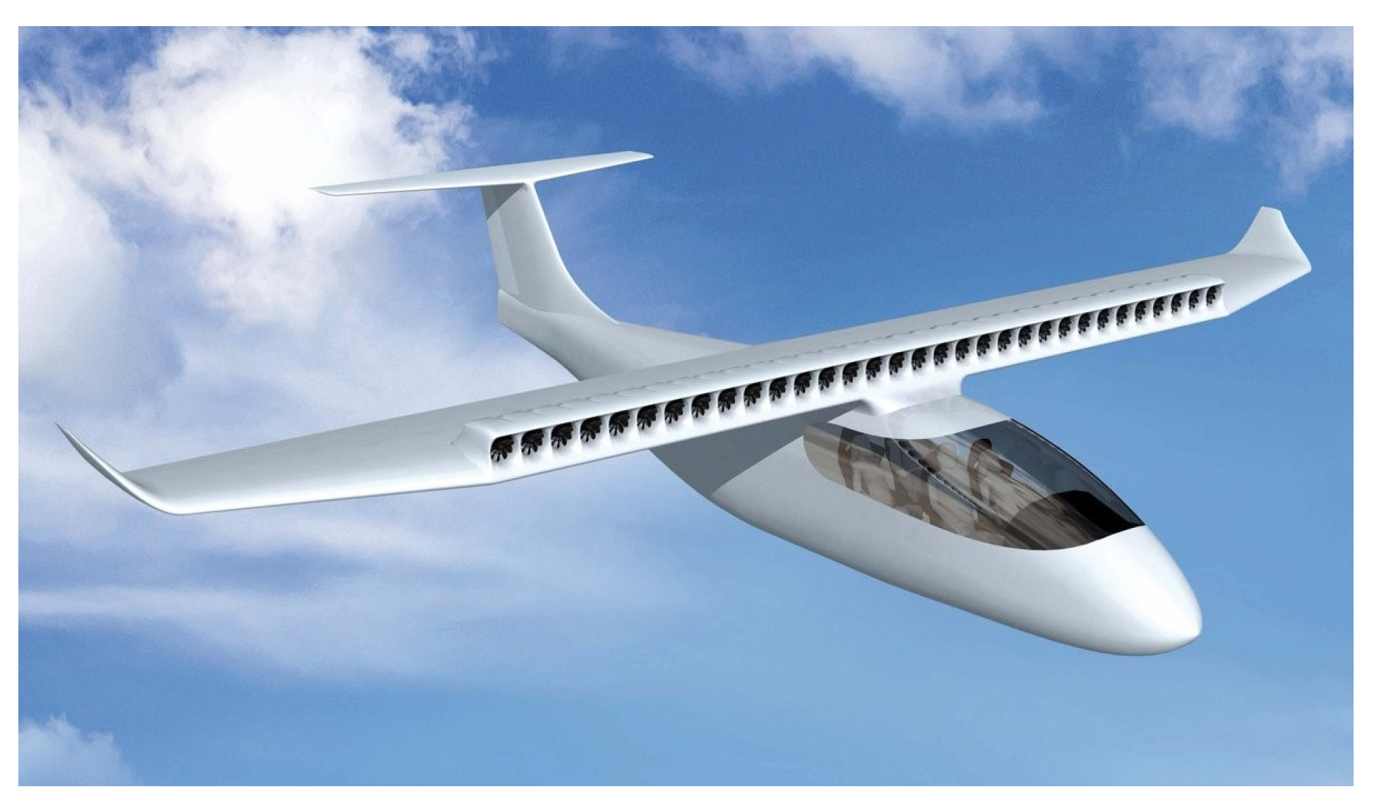
3.3.1. Distributed Electric Propulsion System
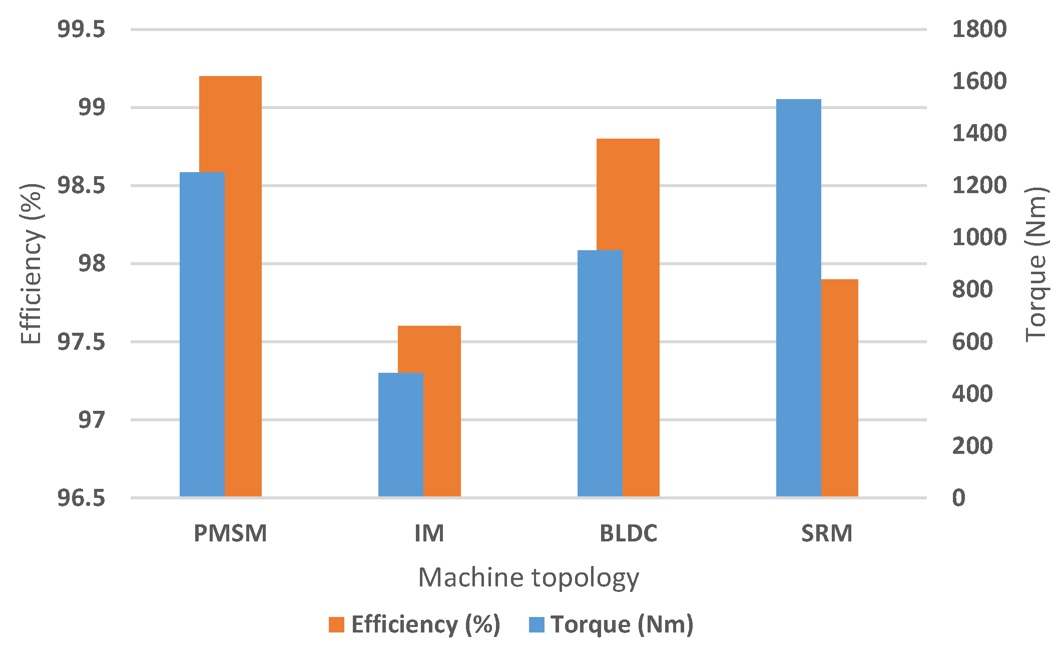
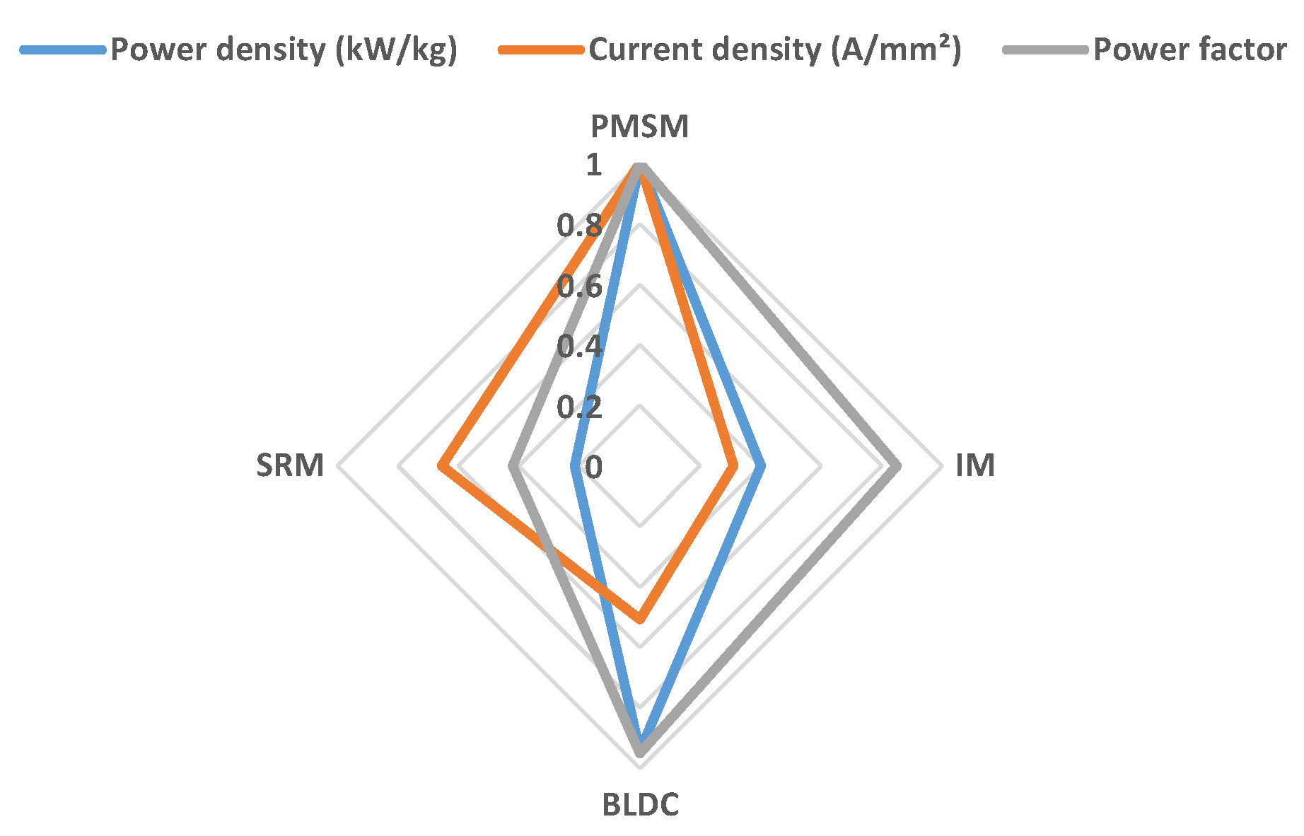
3.3.2. Aircraft Propulsion Architecture and Motor Topologies
3.4. Power Generation
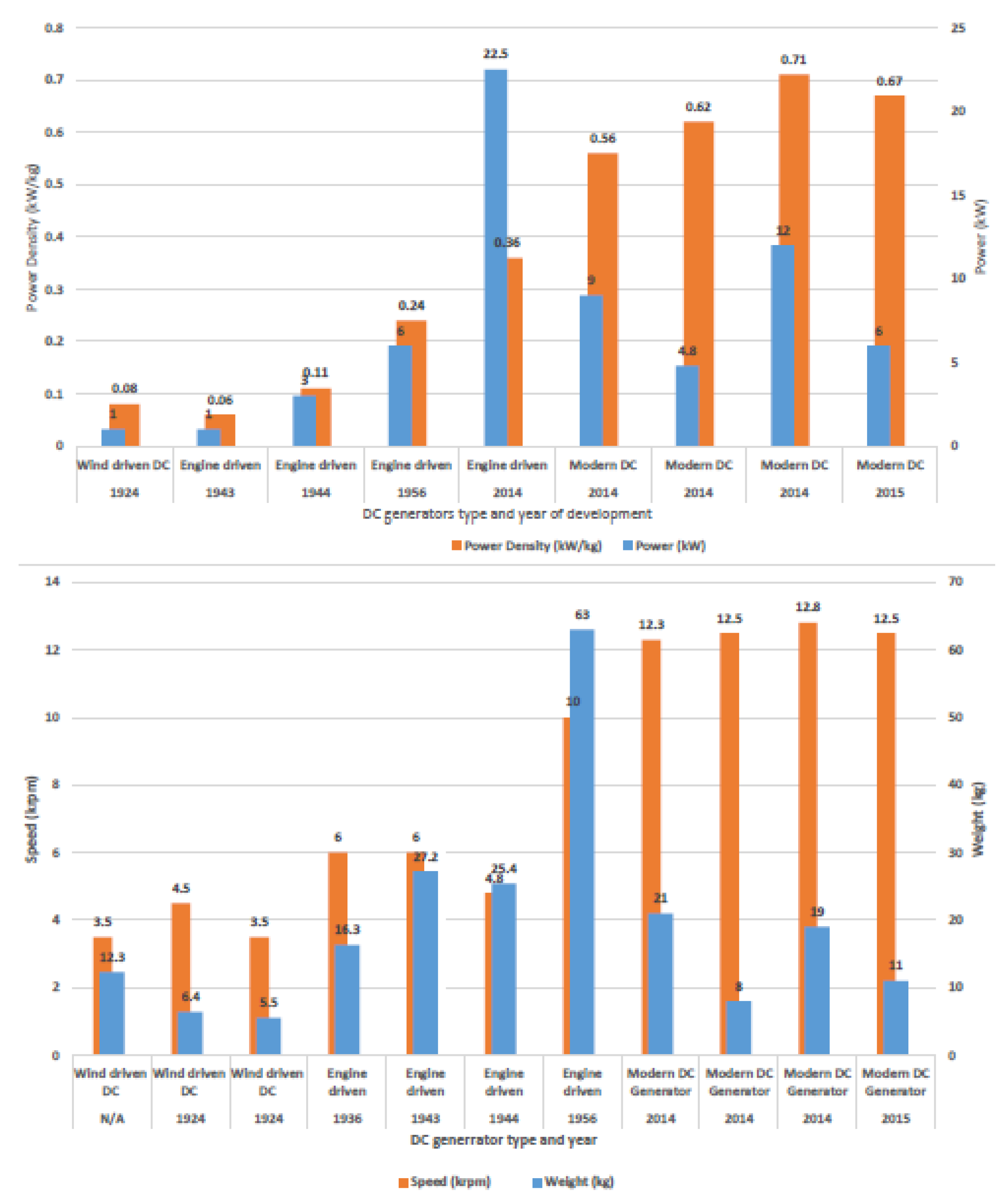
3.4.1. DC Power Generation
3.4.2. AC Power Generation
3.4.3. AC Constant Frequency Systems
3.4.4. AC Variable Speed Constant Frequency System
3.4.5. Power Generation Topologies in MEA
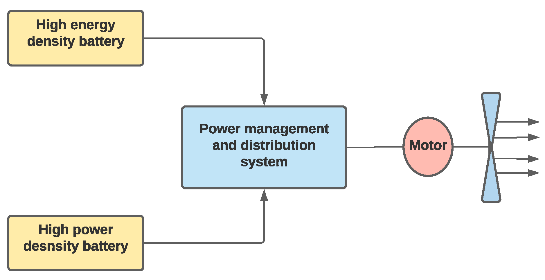
- Battery technology: It provides high efficiency, zero emissions, low maintenance and no centre of gravity movement during flight. It has the disadvantage of increased system weight, battery recycling issues and reduction in flying range of the aircraft. For aircraft usage, Lithium ion batteries are used for large MEA and Lead Acid batteries are used for General Aviation and light aircraft; Nickel Cadmium batteries on helicopters and larger aircraft and Lithium-ion batteries in more electric aircraft. Aircraft such as, Airbus, E-fan and Boeing 787 Dreamliner uses Lithium-ion battery and has 207 Wh/kg specific energy per battery cell [39,40]. A twin-engine aircraft featured by SUGAR volt also relies on this battery technology to create a parallel hybrid propulsion system in the aircraft [11]. A block diagram which shows an overview of the battery technology can be observed in Figure 13.
- Super capacitors (ultra-capacitors): Produces higher power (kW/kg) but lower specific energy capacities than batteries. A common form of super capacitors is EDLC (electrical double layer capacitors) which stores the electrical energy in an electrostatic field, making it durable and offering fast charging and discharging rates, compared to battery technology. It excludes expensive materials such as Cobalt and Lithium in their manufacture, avoiding toxicity and flammability issues. Examples of EDLC can be seen in stop-start systems of modern road vehicles [41]. It can be an alternative to Lithium-ion batteries. Based on Lithium-ion technology, new types of hybrid supercapacitors are also currently being developed. Currently NASA Kennedy Space centre is investigating on the development of ultra-capacitors based on Graphene.
- Hybrid electric: It is the series/parallel hybrid arrangement of the electrical and mechanical drive components. In series arrangement, the electrical supply drives the propeller whereas, in parallel arrangement the propulsion mechanism can be driven by shaft and gears etc. Hybrid electric aircraft are classified as the logical step towards achieving the capabilities of fully electric aircraft [42].
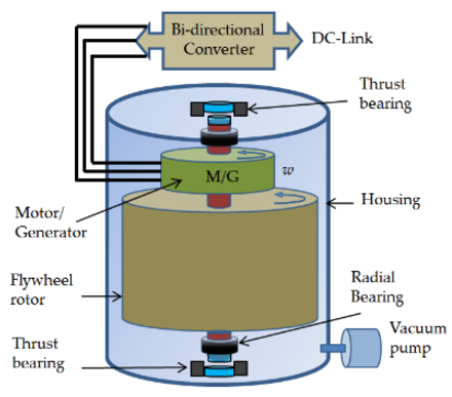
- Flywheels: It stores energy mechanically and have high specific power ratio together with the capability of storing and releasing energy quickly. Recent developments in this technology have created ultra-high-speed flywheels of only tens of kilograms mass running in the magnetically levitated bearings of the housing, with a speed of more than 100,000 rpm. The general components and structure of flywheel can be seen in Figure 14. More details on the operation and principles of flywheel technology can be found in [39,41].
- Fuel cells: It is similar to batteries and produce electricity based on a chemical reaction using chemicals such as oxygen and hydrogen. They offer high energy efficiency and low emissions as the energy is released as an electric current rather than heat. Fuel cells have demonstrated higher specific energies compared to Lithium-ion batteries even though their rate of energy release is much lower. This system requires a hybrid system approach installation on the aircraft to meet the power demands during landing and take-off. On-board hydrogen storage and air supply during the flight are also restricting factors for fuel cells [42]. Fuel cells was demonstrated in Boeing 787 Dreamliner by Sandia National Laboratories [43].
- Photovoltaic technology: The modern photovoltaic (PV) technology is developed with the silicon PC cell in USA. In the recent days there are number of PC technologies available, including organic cells, silicon-based, hybrid PV, polymer cells and thin-film solar cells. These technologies are capable of achieving efficiencies as high as 44%; however, silicon-based PV is the only suitable technology for aircraft that are solar powered due to the cost effectiveness [41].Power generation and storage are the two greatest hurdles faced by electrically powered aircraft designs in conjunction with achieving good aerodynamic efficiency and lowest weight. The current state of art of battery technology has limitations regarding the low values of specific power which restricts the performance on aircraft designs, to slower speed and shorten endurance flight envelops. Development of ground-based support to cope with the rapidly advancing aerospace technology are also becoming a necessity, for example, having novel airport features such as providing electrical power to support the take-off run [39].
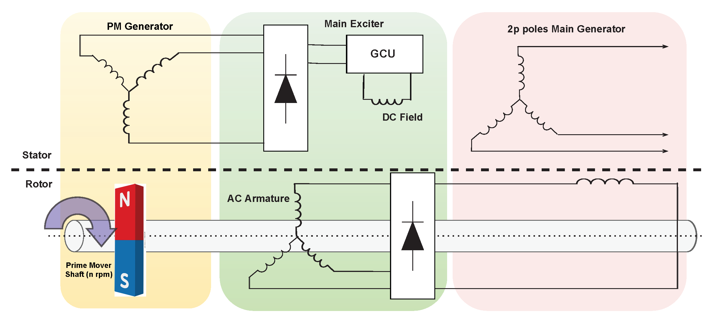
3.4.6. Electrical Machine for Power Generation Application in Aircrafts
- Reduce system complexity.
- Reduce failure probabilities.
- Increase system efficiency and power density.
- Generator driven by the engines to create electricity.
- A pneumatic system that bleeds air off the engine to power other systems such as hydraulic system.On the other hand, a more electric aircraft will have the following factors,
- Uses more electricity than pneumatics.
- Increased fuel efficiency.
- Less noise and drag.
- Lower maintenance tasks and costs.
- More efficient power generation, use and distribution.
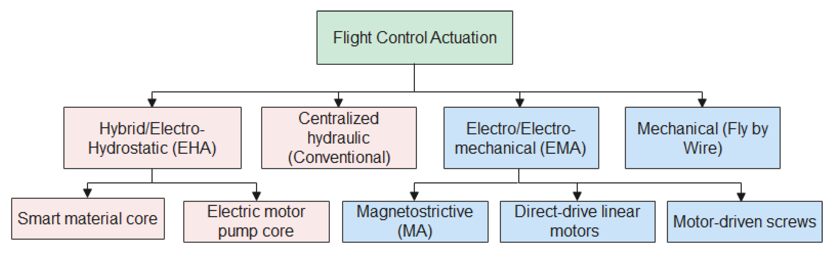
4. Actuation
4.1. Conventional Hydraulic System
4.2. Primary and Secondary Flight Control Actuation System
4.2.1. Ailerons
4.2.2. Rudders
4.2.3. Elevators
4.2.4. Spoilers
4.2.5. Slats
4.2.6. Flaps
4.2.7. Landing Gear
4.3. Electric Actuator Architecture for MEA
4.3.1. Electro Hydrostatic Actuator
- Pump performance and life—Pre-existing pumps are large displacement ones with standard efficiency; however, EHA requires high-speed, low-displacement, high-frequency reversals with low losses.
- Electric motor efficiency and fire risks.
- Packaging of the power electronics and reliability.
- Heat rejection problem.
- Cold start [61].
4.3.2. Electro-Mechanical Actuator
- EMA suffers from fatigue failure such as, thermal failure and mechanical jam restricting the development of EMA. Therefore, EHA will be the main electrically powered actuator technology for the primary flight control of commercial aircraft.
- EMA’s existing redundancy can increase the reliability unilaterally.
- Fault isolation, fault diagnosis and health management for EMA is not developed well.
4.4. Electrical Machine Topology in Aircraft Actuators
5. Future Requirements and Development Discussion
- Motors, generators and inverters needs to be developed to obtain a specific weight, power and reliability for commercial application.
- Specific power will need to be improved by a factor of between 5 and 10 from current state of art.
- Thermal management targets need to be compatible with aircraft thermal management system.
- Efficiency needs improvements from 95 to 97/98%.
- Weight reduction.
- Circuit protection and high-power distribution for MW class aircraft power systems.
- Advanced materials: Motor power densities and efficiencies can be improved with better conductors, insulators, magnets, bearings etc. [2].
- Cooling methods employing high thermal conductivity insulation materials or high thermal conductivity fluid [69].
- Forced liquid cooling method that includes water jackets or channel ducts. This method could create adequate cooling on the winding active region but could also result in localised hotspots in the end winding [70].
- Embedded cooling tubes implemented in Litz wire to extract heat produced within the stator winding [71].
- Implementing liquid carrying pipe that directly cools stator end windings of radial flux. It is a cost effective method that can be added to existing machine designs [33].
- Thermal analysis using different slit thickness, high current density, oil cooling in stator and lumped parameter model performance analysis [72].
- Thin-gauge non-oriented steel to reduce iron losses.
- Higher-strength lamination material for the rotor to improve efficiency and reduce machine size [75].
6. Conclusions
Author Contributions
Funding
Institutional Review Board Statement
Informed Consent Statement
Data Availability Statement
Conflicts of Interest
References
- Thomson, R.; Sachdeva, N.; Nazukin, M.; Martinez, N. Aircraft Electrical Propulsion—The Next Chapter of Aviation? In Think Act; Roland Berger Ltd.: London, UK, 2017; pp. 1–32. [Google Scholar]
- Electrical Power Systems. 2018. Available online: https://www.ati.org.uk/wp-content/uploads/2021/09/insight_07-electrical-power-systems.pdf (accessed on 1 December 2021).
- Electromechanical flight actuators for advanced flight vehicles. IEEE Trans. Aerosp. Electron. Syst. 1999, 35, 511–518. [CrossRef]
- Papini, L.; Connor, P.; Patel, C.; Empringham, L.; Gerada, C.; Wheeler, P. Design and testing of electromechanical actuator for aerospace applications. In Proceedings of the 2018 25th International Workshop on Electric Drives: Optimization in Control of Electric Drives (IWED 2018), Moscow, Russia, 31 January 2018. [Google Scholar]
- Madonna, V.; Giangrande, P.; Galea, M. Electrical Power Generation in Aircraft: Review, Challenges, and Opportunities. IEEE Trans. Transp. Electrif. 2018, 4, 646–659. [Google Scholar] [CrossRef]
- Sayed, E.; Abdalmagid, M.; Pietrini, G.; Sa’adeh, N.M.; Callegaro, A.D.; Goldstein, C.; Emadi, A. Review of Electric Machines in More/Hybrid/Turbo Electric Aircraft. IEEE Trans. Transp. Electrif. 2021, 7, 2976–3005. [Google Scholar] [CrossRef]
- Hebala, A.; Nuzzo, S.; Connor, P.H.; Giangre, P.; Gerada, C.; Galea, M. Improved Propulsion Motor Design for a Twelve Passenger All-Electric Aircraft. In Proceedings of the 2021 IEEE Workshop on Electrical Machines Design, Control and Diagnosis (WEMDCD), Modena, Italy, 11 May 2021; pp. 343–348. [Google Scholar]
- Golovanov, D.; Gerada, D.; Xu, Z.; Gerada, C.; Page, A.; Sawata, T. Designing an advanced electrical motor for propulsion of electric aircraft. In Proceedings of the AIAA Propulsion and Energy Forum and Exposition, Indianapolis, IN, USA, 22–24 August 2019. [Google Scholar]
- Bowman, C.L.; Felder, J.L.; Marien, T. Turbo- and Hybrid-Electrified Aircraft Propulsion Concepts for Commercial Transport. In Proceedings of the 2018 AIAA/IEEE Electric Aircraft Technologies Symposium (EATS), Cincinnati, OH, USA, 12–14 July 2018; pp. 1–8. [Google Scholar]
- Holliday, T.B. Applications of electric power in aircraft. Electr. Eng. 2013, 60, 218–225. [Google Scholar] [CrossRef]
- Commercial Aircraft Propulsion and Energy Systems Research: Reducing Global Carbon Emissions; National Academies Press: Washington, DC, USA, 2016; pp. 1–122. [CrossRef]
- Crom, G.C. Electric Drive for Aircraft. Trans. Am. Inst. Electr. Eng. 1947, 66, 1359–1362. [Google Scholar] [CrossRef]
- Airbus. E-Fan X. 2017. Available online: https://www.airbus.com/en/innovation/zero-emission/electric-flight/e-fan-x (accessed on 1 December 2021).
- Wheeler, P.; Sirimanna, T.S.; Bozhko, S.; Haran, K.S. Electric/Hybrid-Electric Aircraft Propulsion Systems. Proc. IEEE 2021, 109, 1115–1127. [Google Scholar] [CrossRef]
- Dahm, W.J.A. Thermal Management in Aerospace Systems. Available online: https://www.researchgate.net/publication/308315742_Thermal_Management_in_Aerospace_Systems (accessed on 1 December 2021).
- Chan, C.C. The state of the art of electric, hybrid, and fuel cell vehicles. Proc. IEEE 2007, 95, 704–718. [Google Scholar] [CrossRef]
- Guzzella, L.; Sciarretta, A. Vehicle Propulsion Systems: Introduction to Modeling and Optimization; Springer: Berlin/Heidelberg, Germany, 2005; pp. 1–291. [Google Scholar] [CrossRef]
- Hiserote, R.M.; Harmon, F.G. Analysis of hybrid-electric propulsion system designs for small unmanned aircraft systems. In Proceedings of the 8th Annual International Energy Conversion Engineering Conference, Nashville, TN, USA, 25–28 July 2010. [Google Scholar]
- Xie, Y.; Savvarisal, A.; Tsourdos, A.; Zhang, D.; Gu, J. Review of hybrid electric powered aircraft, its conceptual design and energy management methodologies. Chin. J. Aeronaut. 2021, 34, 432–450. [Google Scholar] [CrossRef]
- Mi, C.; Masrur, M.A.; Gao, D.W. Hybrid Electric Vehicles: Principles and Applications with Practical Perspectives; John Wiley & Sons: Hoboken, NJ, USA, 2011. [Google Scholar] [CrossRef]
- Benzaquen, J.; He, J.; Mirafzal, B. Toward more electric powertrains in aircraft: Technical challenges and advancements. CES Trans. Electr. Mach. Syst. 2021, 5, 177–193. [Google Scholar] [CrossRef]
- Khowja, M.R.; Vakil, G.; Gerada, C.; Yang, T.; Bozhko, S.; Wheeler, P. Trade-off Study of a High Power Density Starter-Generator for Turboprop Aircraft System. In Proceedings of the IECON Proceedings (Industrial Electronics Conference), Lisbon, Portugal, 14–17 October 2019; pp. 1435–1440. [Google Scholar] [CrossRef]
- Chen, Y.; Bozhko, S.; Fan, L.; Yang, T.; Khowja, M.R. Decoupled model for asymmetrical dual three phase permanent magnet synchronous machine. In Proceedings of the 2019 IEEE International Electric Machines and Drives Conference (IEMDC 2019), San Diego, CA, USA, 12–15 May 2019; pp. 1971–1976. [Google Scholar]
- Kim, H.D.; Perry, A.T.; Ansell, P.J. A Review of Distributed Electric Propulsion Concepts for Air Vehicle Technology. In Proceedings of the 2018 AIAA/IEEE Electric Aircraft Technologies Symposium (EATS), Cincinnati, OH, USA, 9–11 July 2018. [Google Scholar]
- Kim, H.D.; Brown, G.V.; Felder, J.L. Distributed Turboelectric Propulsion for Hybrid Wing Body Aircraft. In Proceedings of the 2008 International Powered Lift Conference, London, UK, 22–24 July 2008; pp. 1–11. [Google Scholar]
- Leehamcoeu. Bjorn’s Corner: Why e in ePlane Shall Stand for Environment, Part 5; LEEHAM News and Analysis: Washington, DC, USA, 2020. [Google Scholar]
- Hebala, A.; Nuzzo, S.; Volpe, G.; Connor, P.H.; Giangrande, P.; Gerada, C.; Galea, M. Feasibility Design Study of High-Performance, High-Power-Density Propulsion Motor for Middle-Range Electric Aircraft. IEEE Int. Symp. Ind. Electron. 2020, 2020, 300–306. [Google Scholar] [CrossRef]
- Lin, H.; Guo, H.; Qian, H. Design of High-Performance Permanent Magnet Synchronous Motor for Electric Aircraft Propulsion. In Proceedings of the 2018 21st International Conference on Electrical Machines and Systems (ICEMS 2018), Jeju, Korea, 7–10 October 2018; pp. 174–179. [Google Scholar]
- Bolam, R.C.; Vagapov, Y.; Anuchin, A. A Review of Electrical Motor Topologies for Aircraft Propulsion. In Proceedings of the 2020 55th International Universities Power Engineering Conference (UPEC 2020), Turin, Italy, 30 September 2020. [Google Scholar]
- Dave, N.; Vakil, G.; Xu, Z.; Gerada, C.; Zhang, H.; Gerada, D. Comparison of slotted and slotless PM machines for high kW/kg aerospace applications. In Proceedings of the 23rd International Conference on Electrical Machines and Systems (ICEMS), Hamamatsu, Japan, 24–27 November 2020; pp. 609–613. [Google Scholar]
- Lawhorn, D.; Han, P.; Lewis, D.; Chulaee, Y.; Ionel, D.M. On the design of coreless permanent magnet machines for electric aircraft propulsion. In Proceedings of the 2021 IEEE Transportation Electrification Conference and Expo (ITEC), Long Beach, CA, USA, 15–17 June 2022; pp. 278–283. [Google Scholar]
- Weimer, J.A. Electrical power technology for the more electric aircraft. In Proceedings of the IEEE/AIAA 12th Digital Avionics Systems Conference, Fort Worth, TX, USA, 25–28 October 1993; pp. 445–450. [Google Scholar]
- Madonna, V.; Walker, A.; Giangrande, P.; Serra, G.; Gerada, C.; Galea, M. Improved thermal management and analysis for stator end-windings of electrical machines. IEEE Trans. Ind. Electron. 2019, 66, 5057–5069. [Google Scholar] [CrossRef]
- Sinnett, M. 787 No-Bleed Systems:Saving Fuel and Enhancing Operational Efficiencies. Aero Q. 2007, 18, 6–11. [Google Scholar]
- Boice, W.K.; Levoy, L.G. Basic Considerations in Selection of Electric Systems for Large Aircraft. Trans. Am. Inst. Electr. Eng. 1944, 63, 279–287. [Google Scholar] [CrossRef]
- Roboam, X. New trends and challenges of electrical networks embedded in “more electrical aircraft”. In Proceedings of the 2011 IEEE International Symposium on Industrial Electronics (ISIE 2011), Gdansk, Poland, 27–30 June 2011; pp. 26–31. [Google Scholar]
- Moir, I.; Seabridge, A. Aircraft Systems: Mechanical, electrical, and avionics subsystems integration. Aircr. Syst. Mech. Electr. Avion. Subsystems Integr. 2008, 52, 1–504. [Google Scholar] [CrossRef]
- Andrade, L.; Tenning, C. Design of the Boeing 777 Electric System. IEEE Aerosp. Electron. Syst. Mag. 1992, 7, 4–11. [Google Scholar] [CrossRef]
- Bolam, R.C.; Vagapov, Y.; Anuchin, A. Review of Electrically Powered Propulsion for Aircraft. In Proceedings of the 2018 53rd International Universities Power Engineering Conference (UPEC), Glasgow, UK, 4–7 September 2018. [Google Scholar]
- Gohardani, A.S.; Doulgeris, G.; Singh, R. Challenges of future aircraft propulsion: A review of distributed propulsion technology and its potential application for the commercial aircraft. Prog. Aerosp. Sci. 2011, 47, 369–391. [Google Scholar] [CrossRef]
- Libich, J.; Maca, J.; Vondrak, O.C.; Sedlarikova, M. Supercapacitors: Properties and applications. J. Energy Storage 2018, 17, 224–227. [Google Scholar] [CrossRef]
- Pornet, C.; Isikveren, A.T. Progress in Aerospace Sciences Conceptual design of hybrid-electric transport aircraft. Prog. Aerosp. Sci. 2015, 79, 114–135. [Google Scholar] [CrossRef]
- Schroeder, R.; Koehler, T. A Green Machine. 2013. Available online: https://www.boeing.com/news/frontiers/archive/2008/may/ts_sf04.pdf (accessed on 1 December 2021).
- Boglietti, A.; Cavagnino, A.; Tenconi, A.; Vaschetto, S. The safety critical electric machines and drives in the more electric aircraft: A survey. In Proceedings of the IECON Proceedings (Industrial Electronics Conference), Porto, Portugal, 3–5 November 2009; pp. 2587–2594. [Google Scholar]
- Lafoz, M.; Moreno-Torres, P.; Torres, J.; Blanco, M.; Navarro, G. Design methodology of a high speed switched reluctance generator drive for aircrafts. In Proceedings of the 2016 18th European Conference on Power Electronics and Applications, EPE 2016 ECCE Europe, Karlsruhe, Germany, 5–9 September 2016. [Google Scholar]
- Noland, J.K.; Leandro, M.; Suul, J.A.; Molinas, M. High-Power Machines and Starter-Generator Topologies for More Electric Aircraft: A Technology Outlook. IEEE Access 2020, 8, 130104–130123. [Google Scholar] [CrossRef]
- Radun, A.V. High power density switched reluctance motor drive for aerospace applications. In Proceedings of the Conference Record—IAS Annual Meeting (IEEE Industry Applications Society), San Diego, CA, USA, 1–5 October 1989; pp. 568–573. [Google Scholar]
- Anghel, C. Modeling and simulation of a power generation system with a high power generator. SAE Tech. Pap. 2013, 7. [Google Scholar] [CrossRef]
- Ferreira, C.A.; Richter, E. Detailed design of a 250-kW switched reluctance starter/generator for an aircraft engine. SAE Tech. Pap. 1993. [Google Scholar] [CrossRef]
- Rubertus, D.P.; Hunter, L.D.; Cecere, G.J. Electromechanical Actuation Technology for the All-Electric Aircraft. IEEE Trans. Aerosp. Electron. Syst. 1984, 20, 243–249. [Google Scholar] [CrossRef]
- Torabzadeh, M. Dimensioning Tools of MEA Actuator Systems, Including Modeling, Analysis and Technology Comparison. Ph.D. Thesis, KTH Royal Institute of Technology, Stockholm, Sweden, 2008. [Google Scholar]
- Nagel, N. Actuation Challenges in the More Electric Aircraft: Overcoming Hurdles in the Electrification of Actuation Systems. IEEE Electrif. Mag. 2017, 5, 38–45. [Google Scholar] [CrossRef]
- Wheeler, P.; Bozhko, S. The more electric aircraft: Technology and challenges. IEEE Electrif. Mag. 2014, 2, 6–12. [Google Scholar] [CrossRef]
- Bennett, J.W. Fault Tolerant Electromechanical Actuators for Aircraft. Ph.D. Thesis, University of Newcastle, Callaghan, Australia, 2010. [Google Scholar]
- Aten, M.; Whitley, C.; Towers, G.; Wheeler, P.; Clare, J.; Bradley, K. Dynamic performance of a matrix converter driven electro-mechanical actuator for an aircraft rudder. In IEE Conference Publication; IET: London, UK, 2004. [Google Scholar] [CrossRef]
- Atallah, K.; Caparrelli, F.; Bingham, C.M.; Schofield, N.; Howe, D.; Mellor, P.H.; Maxwell, C.; Moorhouse, D.; Whitley, C. Permanent magnet brushless drives for aircraft flight control surface actuation. In IEE Colloquium (Digest); IET: London, UK, 1999. [Google Scholar] [CrossRef]
- Cossar, C.; Kelly, L.; Miller, T.J.; Whitley, C.; Maxwell, C.; Moorhouse, D. The design of a switched reluctance drive for aircraft flight control surface actuation. In IEE Colloquium (Digest); IET: London, UK, 1999. [Google Scholar] [CrossRef]
- Rea, J. Boeing 777 high lift control system. IEEE Aerosp. Electron. Syst. Mag. 1993, 8, 15–21. [Google Scholar] [CrossRef]
- Divakaran, V.N.; Kumar, G.V.V.R.; Rao, P.S. Aircraft Landing Gear Design and Development; Technical Report; Infosys: Bengaluru, India, 2015. [Google Scholar]
- Mare, J.C. Aerospace Actautors 2; John Wiley and Son: Hoboken, NJ, USA, 2017. [Google Scholar]
- Van den Bossche, D. The A380 flight control electrohydrostatic actuators, achievements and lessons learnt. In Proceedings of the ICAS-Secretariat—25th Congress of the International Council of the Aeronautical Sciences, Hamburg, Germany, 3–8 September 2006; Volume 6, pp. 3383–3390. [Google Scholar]
- Li, J.; Yu, Z.; Huang, Y.; Li, Z. A review of electromechanical actuation system for more electric aircraft. In Proceedings of the AUS 2016—2016 IEEE/CSAA International Conference on Aircraft Utility Systems, Beijing, China, 10–12 October 2016; pp. 490–497. [Google Scholar]
- Alle, N.; Hiremath, S.S.; Makaram, S.; Subramaniam, K.; Talukdar, A. Review on electro hydrostatic actuator for flight control. Int. J. Fluid Power 2016, 17, 1–21. [Google Scholar] [CrossRef]
- Gerada, C.; Bradley, K.J. Integrated PM machine design for an aircraft EMA. IEEE Trans. Ind. Electron. 2008, 55, 3300–3306. [Google Scholar] [CrossRef]
- Tursini, M.; Villani, M.; Di Tullio, A.; Fabri, G.; Collazzo, F.P. Nonlinear Model Suitable for the Offline Cosimulation of Fault-Tolerant PM Motors Drives. IEEE Trans. Ind. Appl. 2017, 53, 3719–3729. [Google Scholar] [CrossRef]
- Kakosimos, P.E.; Tsampouris, E.M.; Kladas, A.G.; Gerada, C. Aerospace actuator design: A comparative analysis of Permanent Magnet and Induction Motor configurations. In Proceedings of the 2012 20th International Conference on Electrical Machines, ICEM 2012, Marseille, France, 2–5 September 2012. [Google Scholar]
- Huang, X.; Gerada, C.; Goodman, A.; Bradley, K.; Zhang, H.; Fang, Y. A Brushless DC motor design for an aircraft electro-hydraulic actuation system. In Proceedings of the 2011 IEEE International Electric Machines and Drives Conference, IEMDC, Niagara Falls, ON, Canada, 15–18 May 2011. [Google Scholar]
- Huang, X.; Bradley, K.; Goodman, A.; Gerada, C.; Wheeler, P.; Clare, J.; Whitley, C. Fault-tolerant brushless DC motor drive for electro-hydrostatic actuation system in aerospace application. In Proceedings of the Conference Record of the 2006 IEEE Industry Applications Conference Forty-First IAS Annual Meeting, Tampa, FL, USA, 8–12 October 2006; Volume 1, pp. 473–480. [Google Scholar] [CrossRef]
- Popescu, M.; Staton, D.A.; Boglietti, A.; Cavagnino, A.; Hawkins, D.; Goss, J. Modern Heat Extraction Systems for Power Traction Machines - A Review. IEEE Trans. Ind. Appl. 2016, 52, 2167–2175. [Google Scholar] [CrossRef]
- Galea, M.; Gerada, C.; Raminosoa, T.; Wheeler, P. Design of a high force density tubular permanent magnet motor. In Proceedings of the 19th International Conference on Electrical Machines, ICEM, Rome, Italy, 6–8 September 2010. [Google Scholar]
- Lindh, P.M.; Petrov, I.; Semken, R.S.; Niemela, M.; Pyrhonen, J.J.; Aarniovuori, L.; Vaimann, T.; Kallaste, A. Direct liquid cooling in low-power electrical machines: Proof-of-concept. IEEE Trans. Energy Convers. 2016, 31, 1257–1266. [Google Scholar] [CrossRef]
- Arumugam, P.; Xu, Z.; La Rocca, A.; Vakil, G.; Dickinson, M.; Amankwah, E.; Hamiti, T.; Bozhko, S.; Gerada, C.; Pickering, S.J. High-speed solid rotor permanent magnet machines: Concept and design. IEEE Trans. Transp. Electrif. 2016, 2, 391–400. [Google Scholar] [CrossRef] [Green Version]
- Yang, Y.; Bilgin, B.; Kasprzak, M.; Nalakath, S.; Sadek, H.; Preindl, M.; Cotton, J.; Schofield, N.; Emadi, A. Thermal management of electric machines. IET Electr. Syst. Transp. 2017, 7, 104–116. [Google Scholar] [CrossRef] [Green Version]
- Nategh, S.; Krings, A.; Huang, Z.; Wallmark, O.; Leksell, M.; Lindenmo, M. Evaluation of stator and rotor lamination materials for thermal management of a PMaSRM. In Proceedings of the 2012 20th International Conference on Electrical Machines, ICEM, Marseille, France, 2–5 September 2012; pp. 1309–1314. [Google Scholar]
- Oda, Y.; Okubo, T.; Takata, M. Recent development of non-oriented electrical steel in JFE steel. JFE Tech. Rep. 2016, 21, 7–13. [Google Scholar]
- Krings, A.; Boglietti, A.; Cavagnino, A.; Sprague, S. Soft Magnetic Material Status and Trends in Electric Machines. IEEE Trans. Ind. Electron. 2017, 64, 2405–2414. [Google Scholar] [CrossRef]
- Wu, S.; Tian, C.; Zhao, W.; Zhou, J.; Zhang, X. Design and Analysis of an Integrated Modular Motor Drive for More Electric Aircraft. IEEE Trans. Transp. Electrif. 2020, 6, 1412–1420. [Google Scholar] [CrossRef]
- Abebe, R.; Vakil, G.; Calzo, G.L.; Cox, T.; Lambert, S.; Johnson, M.; Gerada, C.; Mecrow, B. Integrated motor drives: State of the art and future trends. IET Electr. Power Appl. 2016, 10, 757–771. [Google Scholar] [CrossRef] [Green Version]
- Bi, Y.; Liu, Q.; Zhu, S.; Liu, C.; Wang, K.; Hu, Y. Design and Analysis of Dual Three-Phase Winding PMSM for Integrated EMA. In Proceedings of the 2021 IEEE 4th International Electrical and Energy Conference, CIEEC, Wuhan, China, 28–30 May 2021. [Google Scholar]


| Name | Time Frame | Propulsion Architecture | Component | Component Power | Component Performance |
|---|---|---|---|---|---|
| Boeing | 2030-40 | Parallel hybrid | Motor | 1.3–5.3 MW | 3–5 kW/kg |
| NASA N3X | 2030-40 | Turbo-electric | Generator Motor | 30 MW 4 MW | >10 kW/kg |
| NASA | 2030-40 | Parallel turbo-electric | Generator | 1.45 MW | 13 kW/kg |
| STARCABL | - | Electric | Motor | 2.6 MW | - |
| Airbus | 2015-25 | Hybrid Electric | Generator Motor | - | - |
| Electric System | Battery | |||
|---|---|---|---|---|
| Aircraft Requirement | Power Capability (MW) | Specific Power (kW/kg) | Specific Energy (Wh/kg) | |
| Regional/Single-aisle | Parallel hybrid | Motor: 1–6 | >3 | >800 |
| All electric | Motor: 1–11 | >6.5 | >1800 | |
| Turbo electric | Motor: 1.5–3 | >6.5 | - | |
| Generator: 1–11 | - | |||
| General aviation and commuter | Parallel hybrid | Motor < 1 | >3 | >250 |
| All electric | Motor < 1 | >6.5 | >400 | |
| Turbo electric | Motor < 1 | >6.5 | - | |
| Generator < 1 | - | |||
| Twin-aisle | Turbo electric | Motor: 1.5–3 | 10 | - |
| Parallel hybrid | Not studied | - | - | |
| All electric | Not feasible | - | - | |
| Key Performance Indicators | PMSM | BLDC | SRM | IM |
|---|---|---|---|---|
| Weight (kg) | 113.6 | 283.5 | 120.5 | 528.4 |
| Speed (RPM) | 11,500 | 15,000 | 9375 | 29,700 |
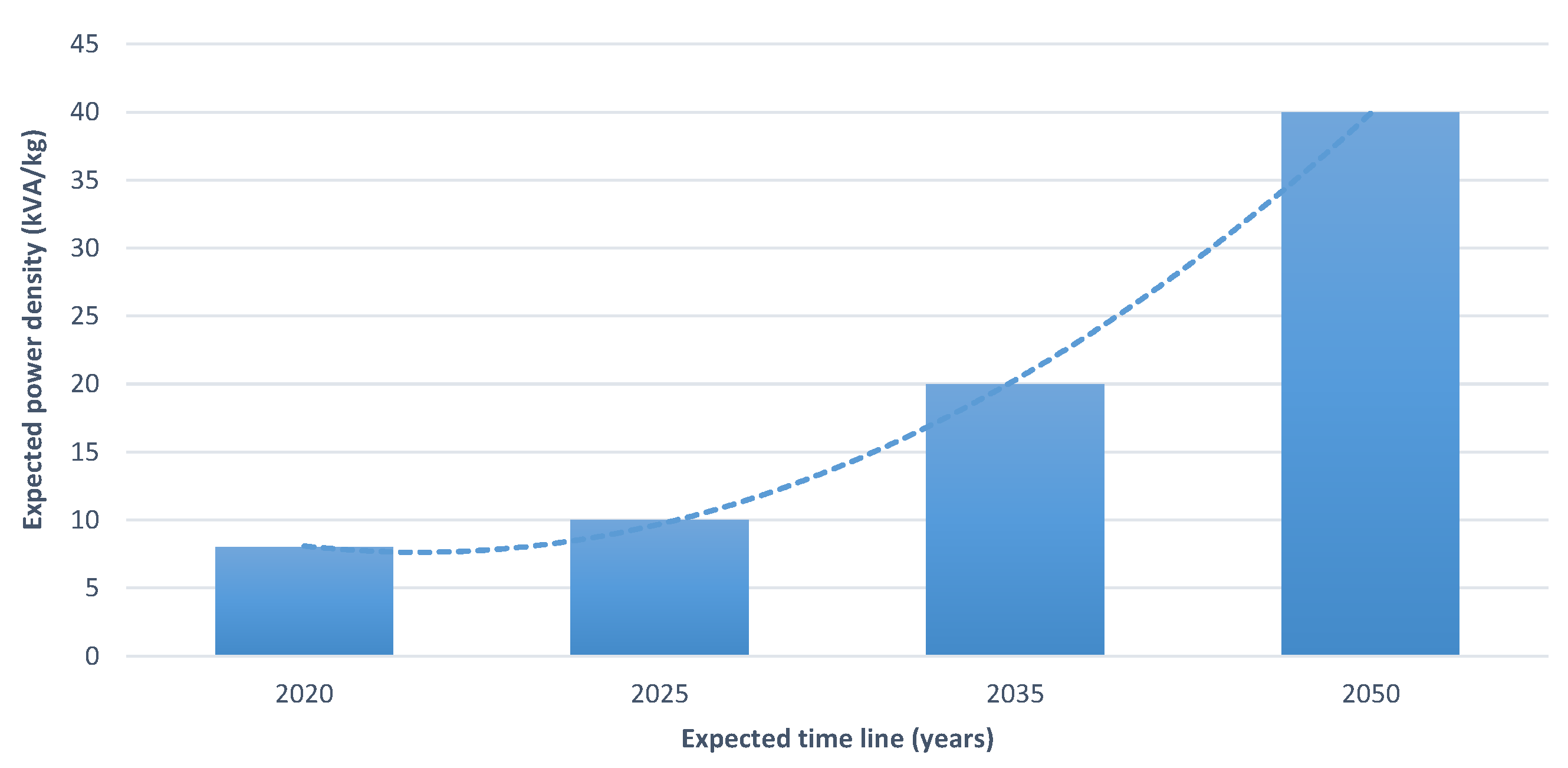
| Timeline | Expected Power Density | Supporting Technology |
|---|---|---|
| Break down strength insulating materials | ||
| 2025 | 10 kVA/kg | Additive manufacturing |
| Liquid cooling | ||
| 2035 | 20 kVA/kg | Magnetic material based on nanocomposite Low loss steel |
| 2050 | 40 kVA/kg | The list above and superconducting material |
| PMSM | SRM | IM | |
|---|---|---|---|
| Temperature | up to 300 C (Samarium-Cobalt PM) | up to 400 C | up to 250 C |
| Name | Motor Topology | Rating | Voltage | Efficiency |
|---|---|---|---|---|
| GE | SRM | 0.25 MW | 0.27 kV DC | 93.1% |
| RR | PMSM | 2.5 MW | 3.00 kV DC | 98.9% |
| Honeywell | WFSM | 1.00 MW | 0.60 kV DC | 97.0% |
| Parameters | Airbus A380 | Boeing 787 |
|---|---|---|
| Number of engines | 4 | 2 |
| Number of generators per engine | 1 | 2 |
| Voltage output generating | 115V AC | 230V AC |
| Rating of Generator | 150 kVA | 250 kVA |
| Number of generators per Axillary power unit | 1 | 2 |
| Generator rating per Axillary power unit | 120 kVA | 225 kVA |
| Urban Air Transport | Sub-Regional Aircraft | Midsize Commercial Aircraft | Large Commercial Aircraft | |
|---|---|---|---|---|
| Power requirement | 150–200 kW | 2 MW propulsive | 22 MW propulsive | 60 MW propulsive |
| Energy requirement | 100–200 kWh | 12 MWh | 55 MWh | 390 MWh |
| Energy Density target | 20 kWh/L | 250 kWh/L | 1 MWh/L | >1 MWh/L |
| Power density targets | 3 kW/kg | 7.5 kW/kg | 12 kW/kg | 20 kW/kg |
| Operating voltage | 230 V | 540 V | 3 kV | >3 kV |
| Efficiency (%) | 90 | 93 | 96 | >96 |
| Machine power | 25 kW | 500 kW | 2 MW | >5 MW |
| Energy Density target year | 2018–2020 | 2024–2026 | 2028–2032 | 2035+ |
| Advanced hybrid or electric architectures | - | Serial | Serial could be possible | Serial is difficult |
| More electric architecture | - | - | Evolved | Evolved |
| Slats/Flaps | Landing Gear | Ailerons | Rudder | Surface Actuation (Spoilers) | |
|---|---|---|---|---|---|
| Common Machine Topology | PMSM | PMSM | PMSM | PMSM | PMSM/SRM |
| Power Requirement (kW) | 1.19–3.5 | <24 | 13 | 20–30 | 25–50 k |
| Torque (Nm) | 34 k | <80 | 29 | 17.9–1.3 k | 5–30 |
| Speed (RPM) | <10,000 | <800 | ∼450 | 2500–9047 | 16,000 |
| Safe and fault-tolerant actuator target year | 2022–2035+ | ||||
| Fully integrated actuator and drives target year | 2024–2035+ | ||||
| Key Performance Indicators | PMSM | BLDC | SRM | IM |
|---|---|---|---|---|
| Power factor | High | High | Low | Low |
| Torque ripple | Low | Low | High | Low |
| Field weakening capability | Low | Low | High | High |
| Risk of demagnetisation | High | High | N/A | N/A |
| Impact of short circuit faults | High | High | Low | Low |
| Cost | High | High | Low | Low |
| Over voltage chances during speeding | High | High | N/A | N/A |
| Inverter requirement | Conventional | Conventional | Special | Conventional |
| Year | Power Requirement | Power Density (kW/kg) | |
|---|---|---|---|
| Propulsion | 2020 2035–2040 | 600 kW 5.3 MW | 3.5 kW/kg 6.5 kW/kg |
| Power Generation | 2020 2035–2040 | 200 kW 60 MW | 3 kW/kg 20 kW/kg |
| Actuation | 2020 2035–2040 | 27 kW 50 kW | 2.2 kW/kg 3.5 kW/kg |
Publisher’s Note: MDPI stays neutral with regard to jurisdictional claims in published maps and institutional affiliations. |
© 2021 by the authors. Licensee MDPI, Basel, Switzerland. This article is an open access article distributed under the terms and conditions of the Creative Commons Attribution (CC BY) license (https://creativecommons.org/licenses/by/4.0/).
Share and Cite
Tom, L.; Khowja, M.; Vakil, G.; Gerada, C. Commercial Aircraft Electrification—Current State and Future Scope. Energies 2021, 14, 8381. https://doi.org/10.3390/en14248381
Tom L, Khowja M, Vakil G, Gerada C. Commercial Aircraft Electrification—Current State and Future Scope. Energies. 2021; 14(24):8381. https://doi.org/10.3390/en14248381
Chicago/Turabian StyleTom, Liya, Muhammad Khowja, Gaurang Vakil, and Chris Gerada. 2021. "Commercial Aircraft Electrification—Current State and Future Scope" Energies 14, no. 24: 8381. https://doi.org/10.3390/en14248381
APA StyleTom, L., Khowja, M., Vakil, G., & Gerada, C. (2021). Commercial Aircraft Electrification—Current State and Future Scope. Energies, 14(24), 8381. https://doi.org/10.3390/en14248381