1. Introduction
The development of advanced devices in a broadly understood field of robotics, which has been progressing for nearly two decades, from year to year reveals more and more a contemporary problem of the need for a new generation of actuators. Two main disciplines for which the technological breakthrough will be of greatest importance are currently humanoid robots and bionic prosthetics. Despite the undeniable advantages of conventional electric actuators, such as low cost of operation, simplicity of control algorithms and bi-directional operation, they are no longer able to meet the increasing demands of modern designs. The expected increase in demand for humanoid robots, adapted to cooperation with humans in a dynamic environment, puts designers not only against the need to protect the drive system from impact loads, but also to provide them with human dynamics and, more importantly, appearance [
1,
2,
3]. These requirements, which form the basis of biomimics, lead to solutions where a given joint is moved in an antagonistic manner, i.e., by a pair of unidirectional actuators. Numerous mechanisms and their configurations have been tested in robotic hands, although they emphasized the unfavourable ratio of power to dimensions of classic actuators. Thus, despite the presence of devices with an impressive number of drives (over 30) [
4,
5,
6], they will not be used in prosthetics due to the space required and the total weight. This fact is confirmed by the most advanced hand prostheses, which, due to the use of the actuators of appropriate power, have a limited number of degrees of freedom [
7,
8].
Against the growing demands, a new group of actuators called artificial muscles, began to emerge. This group includes pneumatic solutions based on the McKibben muscle structures, intelligent materials, e.g., shape memory materials (SMA), dielectric elastomers (DE) as well as twisted coiled polymers (TCP). Unfortunately, factors such as power and control apparatus [
9,
10,
11,
12], heat capacity [
13,
14] or low strain [
15,
16,
17,
18,
19] do not allow them to compete with electric actuators [
17,
20,
21].
With regard to the arguments mentioned above, the design of the electrostatic zipping actuator deserves special attention. Its principle of operation is derived from micro-electro-mechanical devices (MEMS), where, in general, two electrically conductive surfaces are attracted by voltage applied to them [
22,
23]. In recent years, there have been attempts to transfer the concept of these mechanisms from a micro-scale to the dimensions of modern actuators. The work that perfectly illustrates the basics of the described mechanism is [
24], the authors of which used two rectangular electrodes, 100 mm x 12.7 mm, 50 µm thick, where one of them was covered on both sides by 130 µm thick insulator. Both electrodes were mechanically connected on the distal edges. The basic type of actuator was able to lift a weight of 0.2 N suspended in the middle in a time of 1.6 s, for voltage of ~ 7.5 kV. As proved by the authors, by manipulating the basic parameters such as length, width and thickness, it was possible to obtain models with different operating modes—the actuator with the length of 100 mm and the thickness of 1 mm lifting the weight of 12.91 N—while the one with the length of 200 mm and thickness of 20 µm reached 99.84% contraction. Although the authors showed that the use of single drops of liquid dielectric between the plates was enough to reduce the supply voltage by more than 80%, the presented results still required the use of voltage at the levels of several kV. In turn, in [
25] Ito and Saneyoshi transferred the same solution to the size of single millimeters. Their complex muscle consisted of a grid of 16 × 16 electrodes of 2 mm × 2 mm each. What distinguishes their arrangement from others is the stiffening of the electrodes, bringing the work of a single actuator closer to the behaviour of two attracted parallel plates. The maximum stroke of ~40 µm allowed them to lift the weight of 0.85 N. Most importantly, the design of the authors was tested at the voltage not exceeding 350 V, which is a promising result for further work in terms of optimizing the operating parameters of individual actuating units.
Contrary to the examples cited above, Kellaris et al. combine the action of electrostatic and hydrostatic forces [
26]. Hasel actuators are distinguished by a closed foil sleeve with electrodes on both sides and a liquid dielectric inside. Activation of electrostatic forces caused the fluid to move to the region outside the electrodes, changing the shape of the entire muscle, which, with properly selected dimensions and shape of the electrodes, shortened the entire mechanism in the intended direction. The 2 cm × 4 cm actuator achieves 10% strain for a load of 0.02 N and voltage of 10 kV. More importantly, this solution protects the system against electrical breakdown, which made it recognizable as self-healing actuators.
Summarizing the above, it should be stated that the available scientific papers provide basic knowledge on electrostatic zipping actuators. Tests of first prototypes give information both on the mechanical parameters such as force/strain (depending on its geometrical dimensions) and the range of operating voltage. However, there is a serious lack of detailed information about voltage characteristics regarding the pull-in phenomenon. It is typical for MEMS-based mechanisms and may be a decisive argument for the further development of the discussed technology. Due to the fact that prototype works require specific materials and processing techniques, there is a need to develop a methodology for simulating elastic electrostatic muscles numerically. This will not only streamline the prototyping process but also allow one to focus on solutions of the most promising performance. Thus, this article presents mechanical-electrical characteristics, which primarily allow one to investigate in more detail the pull-in effect. In order to determine these characteristics, the authors prepared a simulation program using FEM. It includes not only actual material characteristics, the composite structure of the actuator, but also non-linear electrostatic forces. The results were obtained based on changes in basic parameters, such as: length, width and thickness. An additional parameter, so far not covered in the related literature, being the size of the weld surface to which the load force is applied, was taken into account.
2. Materials and Methods
2.1. Actuator
Electrostatic zipping actuators, as shown by the constructions created so far, despite the identical principle of operation, may differ in several parameters, which has a significant impact on the final work of these devices. In connection with the above, the following assumptions have been made in the current research.
A single muscle consists of two rectangular electrodes connected at the edges, covered on both sides with an insulator. In half of the length of the electrode, a stiffened section can be distinguished, corresponding to the place where the loading force is applied as well as several links in a complex structure (
Figure 1a) are connected to each other. Depending on the technology and type of test, it is a glued or welded area—later in the article, it is referred to as ‘weld’. In order to reduce computational complexity, only half of the actuator is considered (
Figure 1b) due to the symmetry of the entire system.
In the case of material selection, it was decided to choose the materials easily accessible. Thus, it was assumed to use 5 µm steel foil as an electrode, and PET foil as an insulator due to the very high breakdown voltage (1.5 kV for 7 µm). Three samples of each material were subjected to a static tensile test, and the obtained characteristics were implemented in a mathematical model in order to best reflect the actual parameters. The most important material properties of both materials are summarized in
Table 1.
An important assumption of the research was the simulation of mechanisms of the dimensions, which enable one their quick and easy production with the use of commonly available technologies such as laser processing, 3D printing, gluing and welding. Consequently, the muscles of the length of 2.5, 5, 10 and 20 mm and widths of 0.5, 1, 2 and 4 mm were tested. The analysis of the influence of the insulator thickness was guided by the availability of PET film, hence the thicknesses of 1, 3, 7 and 12 µm were selected.
2.2. FEM Configuration
Simulations of the electrostatic muscle behaviour were based on the ABAQUS2020 environment using the Finite Element Method. This allowed one to freely change all individual parameters, starting from geometric dimensions, through the type of finite elements used and ending with solution algorithms.
Given the significant difference between the thickness (single micrometres) and the length/width (millimetres) of the actuator (L/t > 100), the actuator was modelled using shell finite elements with 6 degrees of freedom (DOF) which are recommended for such objects [
27]. Moreover, nonlinear analysis was used for the same reason.
In order to reproduce the multi-layer structure of the actuator, it was modelled as a three-layer composite, in which the thicknesses and types of materials were defined individually for each layer. The material properties for PET and steel foil were used as data obtained from static tensile tests.
The methodology for determination of the optimal mesh size was based on the following scheme. First, the mesh density was selected, for which the simulation time did not exceed the assumed value Then the number of elements was successively increased. For such tests, the mesh size was selected for which the maximum longitudinal stresses did not change by more than 1%, and the maximum transverse displacement did not change by more than 0.1% in subsequent tests.
In order to reflect the actual behaviour of the actuator, in regard to the adopted simplifications (only the lower half of the actuator is considered), one of the edges was restrained (each DOFs), while the other was allowed to move freely/only in the XZ horizontal plane. Due to the lack of a direct solution in order to limit the displacement of the remaining nodes above the base position, a rigid surface was used.
2.3. Electrostatic Forces
The considered muscle under the load takes a non-linear shape, which is a significant problem for the implementation of electrostatic forces in numerical analysis. For this reason, the electrostatic force between two actuator plates is considered in the simulation as a set of smaller parallel pairs of electrodes (
Figure 2). A trapezoid rule for integration of the electrostatic forces was used. Thanks to this a set of separated plates of length
Li, width
W and distance between them
tm can be specified.
Such a simplified model allows for independent consideration of each specified pair of parallel plates. In view of the above, and taking into account the presence of a second dielectric material—PET foil—in order to calculate the electrostatic force between the two covers, the following expression [
24] was used:
where
εm is the dielectric permittivity of the medium,
ε0 is the dielectric permittivity of the vacuum,
A is the surface area,
V is the voltage,
ti is the thickness of the insulator,
tm is the distance between the plates.
The electrostatic forces calculated by this method make it possible to bypass software limitations and implement them in the form of pressure load (only vertical direction) in ABAQUS in an accessible way.
It should also be noted that in all simulations described in the article, air was assumed as the medium between the electrodes.
2.4. Contraction Static Analysis
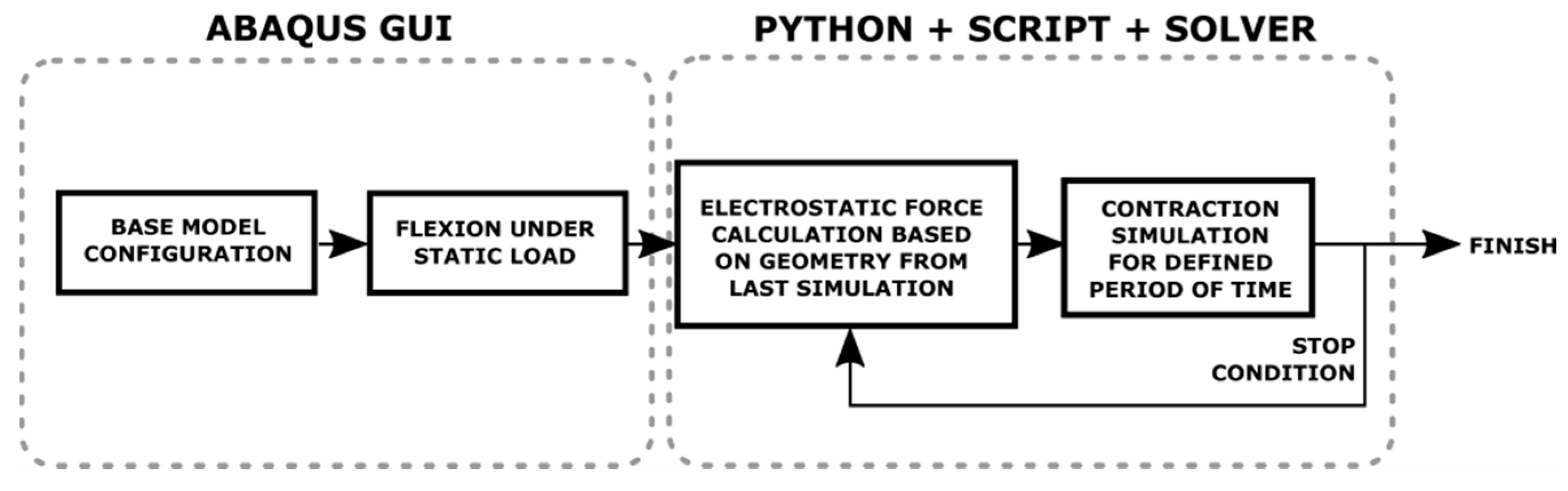
The aim of this article is a static analysis of the concentric contraction of the presented electrostatic zipping actuator. Due to the limitations of ABAQUS software package, which does not allow one to apply electrostatic loads to models based on shell, an original program was created, which combines the capabilities of ABAQUS in terms of the FEM analysis with the physical phenomena required by the research work. As a part of the consolidation, the standard analysis from the GUI level, ABAQUS scripts as well as Python codes were used.
A full numerical simulation of a given model can be divided into two stages (
Figure 3). In the first one, after preparation of the base model with assumed geometric parameters, static loading simulation was carried out from the GUI level. Its goal was to find the load value, applied as a static pressure load, for which the modelled electrostatic muscle deflected to a predetermined level.
The aim of the second step was to simulate contraction of the actuator for a given constant voltage. Electrostatic forces were calculated, using the Python codes and ABAQUS scripts, on the basis of coordinates of mesh points taken from the previous step output and with the formula described above. These forces were saved as a set of pressure loads in an input file (batch) for the next simulation. For each simulation of contraction a constant simulation time was set. The input file prepared in this way was sent to ABAQUS solver for FEM analysis. All described activities in this step were performed in a loop until a stop condition was satisfied, i.e., when the actuator displacement in subsequent steps reached zero.
2.5. Experiment
In the research conducted by the authors, there are 6 variable factors that have a direct impact on the condition of the electrostatic zipping actuator, including: length, width, thickness, weld length, supply voltage and initial deflection. A system defined in this way is classified as a multi-criteria analysis, which can be carried out with the use of, e.g., genetic or swarming algorithms. Taking into account the structure of the simulation program, which requires manual modification of the geometric models, the authors decided to conduct tests that give a clear picture of the influence of individual parameters on the abilities of the actuator, with the methodology described below.
In the first stage, 16 numerical models of different geometries were compared. The thickness of the insulator was assumed as 7 µm, the length of the weld below 1% of the total length of the actuator and the supply voltage of 1 kV. Different initial deflections were assumed for each of the models—10%, 25% and 50% of the maximum deflection, where 100% corresponds to half the length of the actuator.
Model with the highest lifting force was selected and subjected to another, more precise, deflection analysis. The same model was subjected to the insulator thickness test (4 cases). The model selected from this stage has been tested for the effect of the width of the weld, in which 4 values of this parameter were checked: <1%, 25%, 50%, 75%. The number of checked values of individual parameters has been limited to 4 due to the complexity of the simulation program and the number of tests performed. The authors concluded that this number corresponds to the general trend for a given parameter.
3. Results
Before starting appropriate tests, the correctness and quality of the proposed modelling method of elastic electrostatic muscles was verified. For this purpose, a numerical model was created representing the actuator described in [
24]. For the same load, the displacement calculated numerically in ABAQUS was greater by 9% than the displacement of a real actuator. When a voltage of 7 kV was applied, the modelled actuator reached 100% of its contraction, similar to the real one. It should be noted that differences in these displacements might result from differences in mechanical properties of PET films and from neglecting of the Indium Tin Oxide (ITO) layer in the mathematical model. Thus, the above result of the comparative analysis allows one to state that the numerical modelling technique presented by the authors reflects the behaviour of real objects to a high degree of accuracy and can be used to determine the operating characteristics of the considered actuators.
Table 2 shows stroke values obtained for FEM models of different lengths, widths, initial displacements and for the applied DC voltage of 1 kV. In order to read the presented data more easily, the following colours were used: green—the actuator reached 100% strain, white—the actuator reached less than 100% strain, and red—stresses within the actuator exceeded the yield point. For example, the centre of an actuator of 20 mm × 4 mm can move by 10 mm (half its total length). Thus, for the initial deflection of 10%, the centre of the actuator is moved down by 1 mm. After applying a voltage of 1 kV, electrostatic forces lift the centre of the actuator by 1 mm—green. Likewise, the actuator of 10 mm x 1 mm, for the initial deflection of 50% contracted by 0.06 mm.
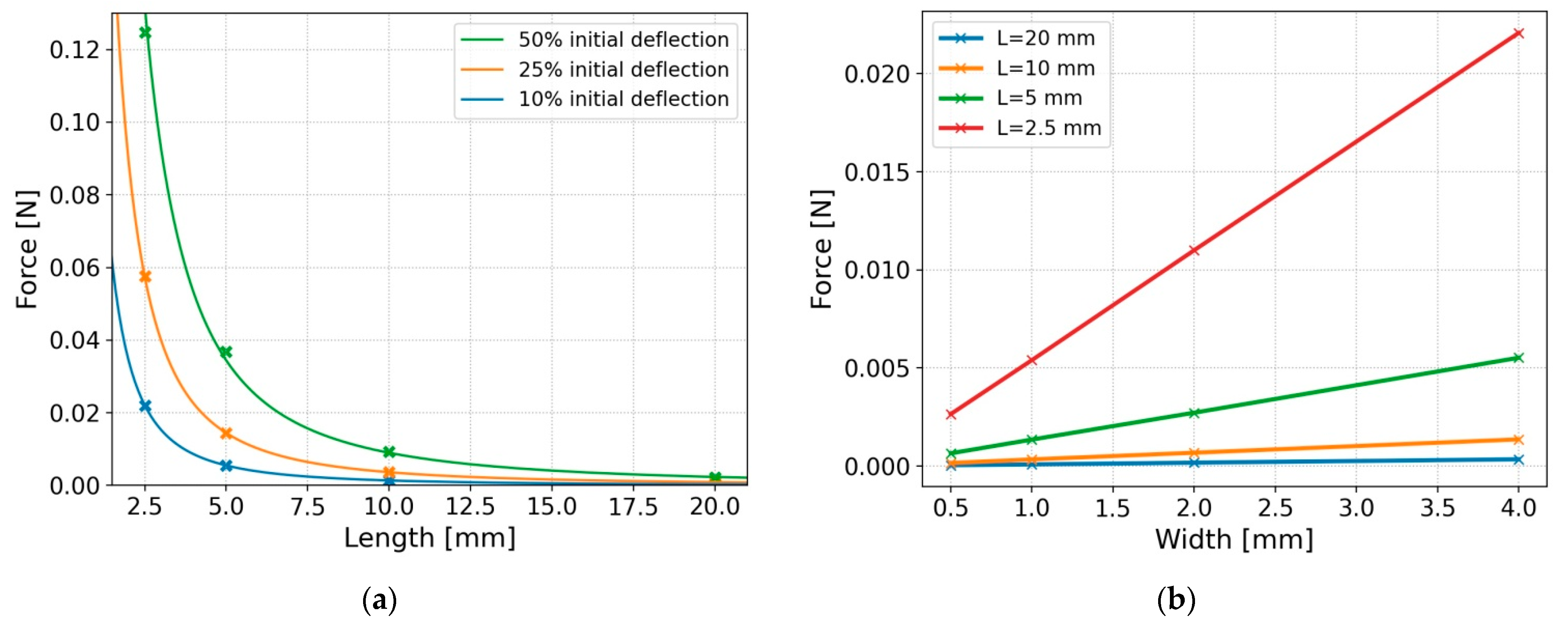
Characteristics of loading forces as a function of the length and width of the actuator are shown below in
Figure 4a,b. It can be seen in
Figure 4b that the force deflecting the actuator to a given initial deflection (10% in this case) increases proportionally with an increase in the width of the actuator. This is also confirmed by the data presented in
Table 1, where regardless of the width of the actuator, the stroke value remains unchanged. This is clear proof that voltage characteristics for different actuator widths are identical.
An increase in the load with a simultaneous decrease in the length of the actuator is due to an increase of its stiffness, as clearly visible in
Figure 4b. While this relationship was indirectly given in the case of the results presented in [
24], the authors of this work decided to extend their investigations to include the analysis of voltage characteristics depending on the length of the actuator.
Figure 5 presents mechanical-electrical characteristics of the actuator for the initial deflection of 10%. On their basis, it can be observed that with an increase in the length of the actuator (i.e., reduction of its stiffness), voltage needed for the full contraction decreases. For the lengths of the actuator equal to 20 mm, 10 mm, 5 mm and 2.5 mm this voltage was 110 V, 190 V, 365 V, 710 V, respectively.
Similarly to MEMS, as tension within the actuator increases its contraction increases exponentially. An important parameter in this technology is so-called pull-in voltage. This is the voltage level beyond which acting elastic forces are unable to balance electrostatic forces and thus the two electrodes of the actuator slap rapidly [
28]. Particular attention should be paid to the fact that in MEMS a system of two parallel plates is generally considered—one of them being stationary and the other being connected by an elastic element. For such a system, it was proved that the pull-in effect occurs for 33% strain [
29]. A non-linear shape of the electrostatic zipping actuator and the results presented in
Figure 5 suggest the existence of differences between the values of the pull-in strain for different lengths of the actuator. Due to the time of each numerical simulation and exponentially growing values, the authors developed an indirect method, which allowed them to estimate the value of the pull-in strain.
Analysis of differences in the displacements of the centre of the actuator in subsequent iterations of simulation (full contraction) allows one to observe that their values in the first stage decrease. Then, after exceeding a certain limit, they begin to increase up to the full contraction of the actuator, as seen in
Figure 6a. By looking at a visible minimum, it is possible to estimate the distance of the actuator from its base position, for which the pull-in phenomenon starts to occur. This value stays between two points, which are selected due to the two smallest displacement values. For example, the smallest displacement values are 3.91 µm and 3.64 µm (green dots on green line), which are calculated for the displacements between 101.16 µm, 97.25 µm and 93.61 µm vertical positions of the lowest part of the actuator. These two extreme points define the range in which the pull-in effect (green shaded area) takes place—in this case, it is 21.9–27.8%. When the value of supply voltage approaches the value of the pull-in voltage, it is possible to estimate more accurately the strain of the pull-in effect, and so for 725 V and 715 V, these ranges are 25.2–27.1% and 26.4–26.8%, respectively.
Using the above method, the ranges of the strain values (blue shaded area) are estimated depending on the length of the actuator, as presented in
Figure 6b. Determined characteristics by their mean values (blue line) indicate that a change in the length of the actuator directly influences the value of the pull-in strain, for which the actuator will contract rapidly and unstably. Shorter actuators, and at the same time more stiff, despite a much greater pull-in voltage, show a significantly larger pull-in strain compared to longer actuators. The maximum difference reaches as much as 15% comparing the longest and the shortest.
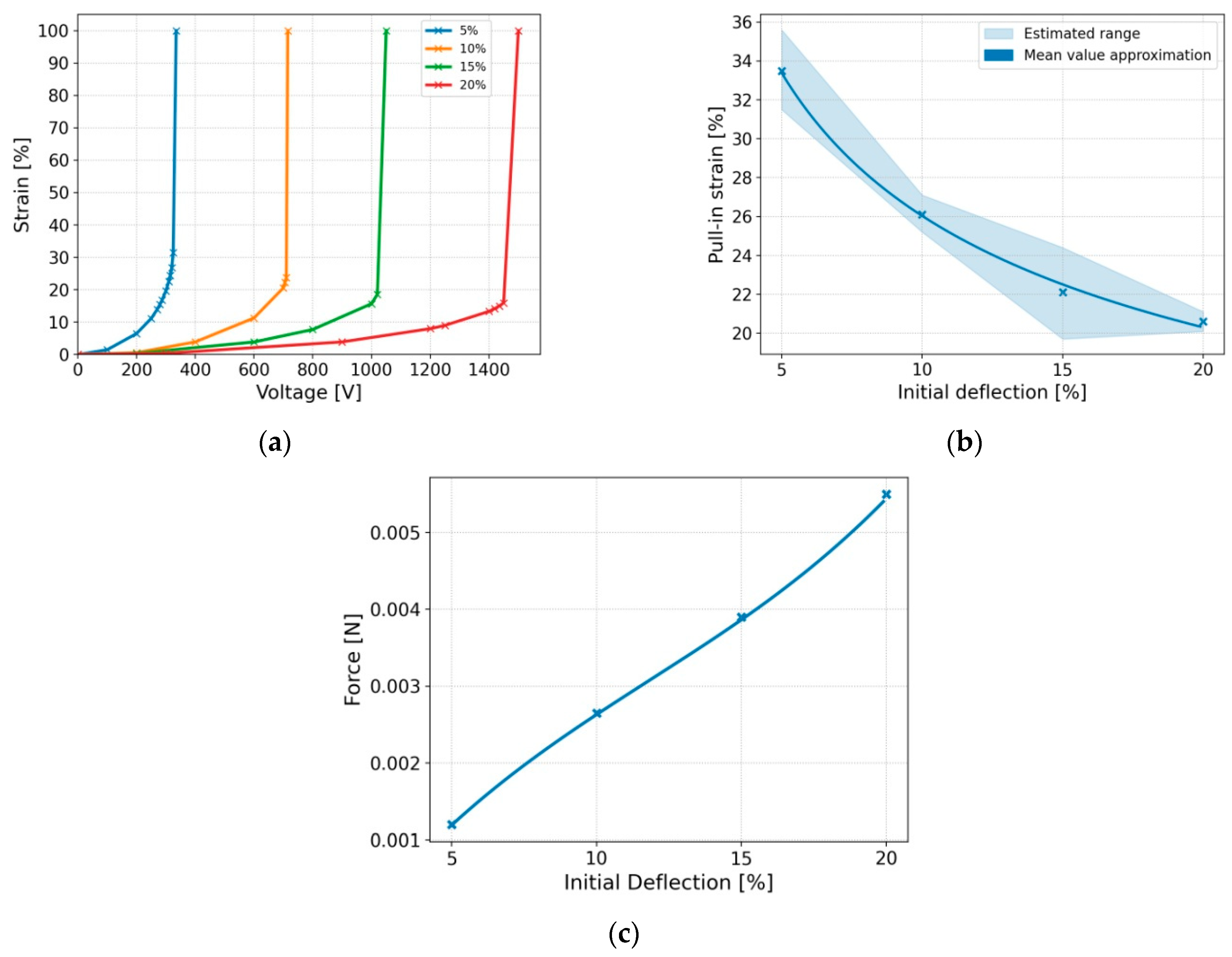
Figure 7 shows the results obtained from another numerical test, in which the influence of the initial deflection is checked on the values of the pull-in strain as well as voltage. The model under investigation had the dimensions of 2.5 mm × 0.5 mm, for which a non-linear increase in the limit voltage was observed along with an increase in the initial deflection. An increase in the initial deflection not only negatively affects the value of the pull-in voltage, but also the range of stable control. In the case of 20% of initial deflection, this range decreased by as much as ~13%.
Another parameter, along with the length of the actuator, having a direct impact on the stiffness of the actuator is its thickness, as presented in
Figure 8. The considered structure consists of two types of materials: steel and PET. As part of the discussed analysis, it was only decided to vary the thickness of the PET layer, as it affects both the stiffness of the structure and the magnitude of electrostatic forces. Simulation results confirm previous observations regarding the stiffness of the actuator. Thus, with an increase in its thickness, both an exponential increase in the pull-in voltage from 378 V for 1 µm to 1290 V for 12 µm as well as an increase in the pull-in strain from 23.8% to 28.7%, are observed. The high convergence of the voltage values for an increasingly thinner PET layer is, in the authors’ opinion, mainly due to the proportion of the materials used. For the PET layer of 1 µm and for the thickness of the electrode of 5 µm, the value of the first one is ~29% of the total thickness, in contrast to the initial model, when the thickness of the PET layer was 7 µm, in which the insulating layers account for ~74%.
The last considered parameter of the actuator, so far neglected in the literature studies on an electrostatic zipping actuator, is the length of the weld surface. Depending on the design concept and dimensions of the device, in order to connect several single electrostatic actuators, they might be glued and additionally stiffened with stops [
25] or stuck with plastic clips [
24]. So, in the first example considered, this length was ~83% and in the second ~6% of the total length of the actuator.
In numerical tests, the FEM model with the smallest thickness was considered, i.e., of 1 µm. The initial deflection in the case of all models was assumed as 10%. Increasing the length of the weld surface from 1% to 50% of the total length of the actuator resulted in an increase in the pull-in voltage from 375 V to 535 V, respectively, as clearly seen from
Figure 9. Contrary to the previous results, increasing this length to 75% resulted in a voltage reduction. The phenomenon itself can be observed in the pull-in strain diagram, where, despite higher values of this parameter for longer welds, the obtained characteristics take the shape of a 3rd order polynomial. There are two reasons for this behaviour. Firstly, an actuator with a weld length >50% begins to behave like an actuator of an increased thickness. Secondly, non-linear elastic characteristic of the actuator, for which two spring constants can be specified, might magnify this effect [
25].
4. Discussion
In this article, for the first time, FEM analysis using shell finite elements has been used to simulate electrostatic zipping actuators. The obtained results not only give a good representation of the performance of real devices, but also allow for easy manipulation of actuator parameters, such as geometric dimensions, composite structure, material properties and the type of solution algorithms. Although the ABAQUS environment has the lack of a built-in possibility of applying electrostatic interactions, the authors proved, it can be solved using the triangulation approximation method. The determined electrostatic forces can be applied in the numerical model in the form of pressure loading.
The pull-in effect is a widely studied phenomenon in the presented article. The obtained voltage characteristics generally show a tendency towards a drop in the pull-in voltage with a decrease in the stiffness of the actuator, which depends on geometrical dimensions such as: length, thickness and weld length. However, the most important conclusion of the current research, not yet discussed in the literature of the field, is the occurrence of changes in the value of the pull-in strain. Contrary to the tension characteristics, increasing the actuator stiffness in any of these ways increases the pull-in strain, which has a huge impact on both the quality of control and the efficiency of multilayer structures. It should be emphasized that these changes are significant and for, e.g., the length of the actuator the difference can be as high as 15%.
Designers of electrostatic actuators face a problem how to find the optimal operating parameters for the target application. On one side focusing on humanoid robots and bionic prostheses depends on both achieving sufficient strength (350 N in isometric contraction of the biceps [
30]) and reduction of supply voltage (size of control systems and electrical safety of bionic devices). For this purpose, geometric parameters such as: length, thickness, as well as operating strain and the weld length can be used. Despite small forces of individual devices, it is possible to connect them into parallel structures, which show much better performance than their larger counterparts. Construction of electrostatic muscles adapted to the requirements of the working environment, force researchers to use numerical models, which due to the non-linear behaviour and a high number of variables, should be the subject of multi-criteria optimization. Nevertheless, the results presented above can be successfully used as offering a general insight into the behaviour of zipping actuators.
The concept of electrostatic zipping actuators brings us closer to biomimic solutions, guaranteeing both flexibility and simplicity of operation, which is a competitive factor for the existing rigid electric actuators. Unfortunately, forces generated by individual devices still separate them from human muscles. In the case of the actuator of length of 2.5 mm, thickness of 12 µm and the weld length 0.01 L the generated force reaches 0.007 N (for 10% initial deflection). Increasing the weld length to 0.75 L increases this force to 0.03 N. A single structure of 1000 mm
2 surface area [
30] composed of such actuators can reach a maximum force of 30 N. These results are still unsatisfactory in relation to the minimum, set by the performance of human muscles, although they significantly distinguish electrostatic muscles from other solutions from the category of artificial muscles.
Taking into account the above considerations, it should be stated that the concept of electrostatic zipping actuators deserves special attention in the field of artificial muscles. The results of the research carried out so far shows a noticeable potential, but at the same time proves that the units of the best performance are still these of the micro, if not of the nano, scale. These conclusions indicate a number of technological challenges, due to the method of production of three-dimensional devices at this scale. Nevertheless, this knowledge is already developed by a separate field, which is formed by micro electromechanical devices. From the point of view of today’s knowledge further simulation tests on a much smaller scale and for a wider range of parameters tested, are certainly required. This will allow for the best possible determination of electrical and mechanical characteristics of such actuators as well as the verification of their limitations.
5. Conclusions
Taking into account the simulation results and their extensive discussion, the most important conclusions of the research carried out by the use of FEM on the influence of geometric parameters on the operation of an electrostatic actuator, include:
- Muscle simulation using shell finite elements provides results that closely match the performance of real actuators.
- Due to the non-linear shape of the actuator, the distance for which the pull-in effect occurs is variable, depending on the length, thickness, weld width and initial deflection of the actuator. This phenomenon turns out to be so important that in extreme cases it may limit the range of stable muscle control from ~ 35% to ~ 11% of its total strain.
- As the stiffness of the actuator increases, an increase in the value of the supply voltage and the range of stable operation is observed.
- The width of the weld (the area connecting two actuators or the place where the loading force is applied) directly affects the value of the required supply voltage and the range of stable operation. It should be noted that the scope of these changes, unlike other factors, is variable. For the weld width exceeding 50% of the total length, a decrease in the supply voltage value is observed, despite its initial upward trend.
In their future research, the authors foresee the investigation single-micrometer devices. According to the presented results, they should show much lower values of the supply voltage. At the same time, it is required to increase the density of measurements in order to best represent the nonlinear operating characteristics of electrostatic zipping actuators. Nevertheless, all the data presented can be definitely taken as a benchmark for future work by other research teams.


