Article

Distributed Control Strategy of Single-Phase Battery Systems for Compensation of Unbalanced Active Powers in a Three-Phase Four-Wire Microgrid

by
Watcharakorn Pinthurat
and
Branislav Hredzak
*
School of Electrical Engineering and Telecommunications, The University of New South Wales, Sydney 2052, Australia
*
Author to whom correspondence should be addressed.
Energies 2021, 14(24), 8287; https://doi.org/10.3390/en14248287
Submission received: 13 November 2021 / Revised: 28 November 2021 / Accepted: 2 December 2021 / Published: 9 December 2021
(This article belongs to the Topic Energy Storage and Conversion Systems)

Abstract

:
Unbalanced active powers can affect power quality and system reliability due to high penetration and uneven allocation of single-phase photovoltaic (PV) rooftop systems and load demands in a three-phase four-wire microgrid. This paper proposes a distributed control strategy to alleviate the unbalanced active powers using distributed single-phase battery storage systems. In order to balance the unbalanced active powers at the point of common coupling (PCC) in a distributed manner, the agents (households’ single-phase battery storage systems) must have information on the active powers and phases. Inspired by supervised learning, a clustering approach was developed to use labels in order to match the three-phase active powers at the PCC with the agents’ phases. This enables the agent to select the correct active power data from the three-phase active powers. Then, a distributed power balancing control strategy is applied by all agents to compensate the unbalanced active powers. Each agent calculates the average grid power based on information received from its neighbours so that all agents can then cooperatively operate in either charging or discharging modes to achieve the compensation. As an advantage, the proposed distributed control strategy offers the battery owners flexibility to participate in the strategy. Case studies comparing performance of local, centralized, and the proposed distributed strategy on a modified IEEE-13-bus test system with real household PV powers and load demands are provided.

Graphical Abstract

1. Introduction

In recent years, unbalanced conditions in three-phase four-wire power systems, due to high penetration and uneven allocation of single-phase rooftop PV systems and load demands, have become exacerbated [1]. Specifically, the unbalanced active powers among phases and between single-phase PV systems and local loads can have a negative effect on power quality and system reliability due to large current flowing through neutral wires. The unbalanced conditions in the three-phase four-wire power systems can be described as a condition when the voltages or currents are not equal in the magnitudes and/or the phase angles of voltages and currents are not equal in consecutive sequence of phasors [2]. Since the voltages and/or currents are unbalanced, the active powers among phases in the three-phase system are also unbalanced.
There are several strategies to mitigate the unbalanced conditions. Traditionally, the unbalanced conditions were considered to be static since the penetration and variation of renewable energy sources (RESs) in power systems were low. Traditional compensation strategies, include using static synchronous compensators (STATCOMs) [3], passive devices, such as shunt capacitors [4], equalizing power generation, and load consumption [5], or using STATCOM with delta cascaded H-bridge (CHB) converter [6]. Moreover, some traditional methods to mitigate the neutral current and neutral to ground voltage (NGV) rise by resizing the neutral conductor, improving grounding and installing a passive harmonic filter were introduced in [7,8,9,10], respectively. However, owing to high variation in a number of single-phase PV rooftop systems distributed in the three-phase four-wire power systems, balancing between single-phase loads and rooftop PV sources and among the three phases becomes more difficult and, hence, the traditional methods cannot properly manage the unbalanced conditions.
Recently, the unbalanced conditions have been mainly compensated by designing new power electronic converters, managing electric vehicles (EVs) based on arrival and departure times, and employing energy storage systems (ESSs). The control strategies based on these approaches can be broadly divided into three main frameworks: centralized, decentralized, and distributed. A centralized controller requires information from all agents to be sent to a central control unit. The communication system should be fast and reliable, which can be challenging in practical distribution systems. A decentralized controller can make decisions based on only local observations, but the capability of resources may not be fully utilized due to the lack of cooperation between agents. A distributed controller is able to achieve cooperative control using the agent’s own (and neighbouring agents’) information [11].

1.1. Unbalance Compensation by Power Electronic Converters

As an active compensation strategy, three-phase four-leg topology based PV-VSI inverters with fixed capacity [12] and with dynamic capacity [13] were designed to alleviate the neutral current caused by the unbalanced loads. However, different network parameters, e.g., negative and zero sequence components of line impedance can affect the system stability and additional switching devices are required for the compensation. In [14], a distributed control method of a single-phase H-bridge PV-VSI was proposed for compensating the voltage unbalance factor (VUF) at a critical bus. Steinmetz design was employed for calculating required reactive power injections at different PV and load connections. However, if an upstream network (medium voltage side) was imbalanced and downstream loads were not constant power, using the Steinmetz design to calculate the required reactive powers for compensation may not be applicable. Furthermore, a reactive power control method with a centralized controller was developed for single-phase H-bridge VSI of DGs to compensate zero and negative sequence current components [15]. Power factors of DGs were controlled to obtain required reactive power, and Karush–Kuhn–Tucker (KKT) optimization algorithm using instantaneous power analysis was used to minimize the unbalanced conditions. The required reactive powers were shared among DGs through communication links by considering capacity ratings of the VSIs. However, there was a trade-off between compensation of the negative sequence current component and the zero sequence current component. The authors in [16] developed a current control strategy based asynchronous parallel pattern search (APPS) method for three single-phase full-bridge VSIs to reduce the voltage unbalance. Different indicators of the voltage unbalance were discussed. Moreover, a geometric norm based on a phasor diagram was introduced to examine the unbalanced conditions with different indicators. Then, the geometric norm was used as an objective function for obtaining asymmetrical current references for the three single-phase full bridge VSIs to inject the required current to the grid. However, the new power converters required three single-phase full bridge inverters, twelve switching devices, and three isolated DC voltage sources, thus increased additional cost.

1.2. Unbalance Compensation by Management of EVs/PEVs

Some strategies using EV chargers for the unbalance compensation were proposed. Impact of uncoordinated plug-in EVs was investigated in [17]. Two coordinated control strategies were proposed for PEVs to regulate bus voltages and minimize voltage unbalance. First, a centralized active power charging control method was introduced for charging PEVs using genetic algorithm (GA). Second, a decentralized reactive power discharging control system was developed for the voltage regulation and voltage unbalance compensation. PEV inverter was locally assigned to discharge the reactive power based on reactive power droop controller at the bus having a poor voltage profile. In [18], two distributed consensus algorithms were proposed for PV units and PEVs to regulate bus voltages and to reduce voltage unbalance. The first algorithm was developed to maximize utilization of ES capacity of PEVs subject to ES constraints by controlling charge and discharge of PEV ESs, while the second algorithm was used to minimize the active power curtailment (APC) of PV units in case of PEVs having insufficient capacity for reduction of voltage rise. Arrival and departure times of PEVs used for verification of the proposed algorithms were selected randomly. In [19], an energy management system (EMS) of PV units and PEVs using decision making optimization based demand response (DR) was introduced to minimize VUF. PEV owners could decide to participate in various charging and discharging options offered by an aggregator. A central communication system was used as all PEVs were required to send all data to the aggregator. Owner preferences offered flexibility, while the combination of PVs and PEVs ensured minimizing VUF. Comprehensive indices represented by current waveforms were derived in [20]. The indices were then used to analyse the unbalanced conditions and harmonic distortion at the fundamental and harmonic currents of three-phase EV chargers during unbalanced charging and grid voltage unbalance. Two different EV technologies were used for the verification.

1.3. Unbalance Compensation by ESSs

ESSs have widely been employed to minimize the unbalanced conditions in three-phase four-wire power systems. Central energy storage, also called community energy storage (CES), with a centralized controller [21], and single-phase distributed energy storage system (DESs) with a distributed cooperative control strategy [22], respectively, were proposed to alleviate the neutral current and NGV rise in a multi-grounded three-phase four-wire distribution system. The current unbalance factor (CUF) was used to quantify the the unbalanced conditions. The authors assumed that all single-phase household installed PV systems were willing to participate in the control strategy. A three-phase damping control strategy for a CES connected at the end of line feeder was proposed in [23] to address over-voltage and voltage unbalance. The control strategy was applied to split DC-bus capacitors of VSI to consume (deliver) asymmetrical (negative and zero sequence components) phase currents from (to) the grid by adjusting the damping conductance. Based on the damping conductance, the VSI was able to operate in resistive mode. Comparing the proposed controller with the positive sequence control method, less current was required. However, the damping capacitance was a function of the VSI capacity; hence, performance of the proposed control strategy may be limited by the inverter size. Furthermore, a fuzzy logic control strategy was proposed in [24] for controlling individual single-phase DES based on the phase voltage deviation and the battery SoCs to mitigate voltage unbalance and voltage rise. Park’s transformation was used to obtain the positive, negative, and zero sequence voltage components. It was also used to determine which phase DES should take action for the balancing process.
In addition, a distributed control strategy was proposed for single-phase distributed generators (DGs) to alleviate the unbalanced powers at PCC, but without considering variability and fluctuation of RESs [25]. It can be observed from the literature review that few studies focused on using single-phase distributed ESSs with distributed control strategies to mitigate the unbalanced conditions. The comparison of existing techniques for compensation of unbalanced conditions is summarized in Table 1. As illustrated in the table, the strategy proposed in this paper employs single-phase distributed battery storage systems and a distributed control strategy to minimize VUF and CUF in a modified IEEE-13-bus test system.
To employ single-phase battery storage systems distributed in a three-phase four-wire microgrid for compensation of unbalanced conditions, the battery storage systems must know information about the active powers and phases at the PCC so that the agents (single-phase battery storage systems) can select the correct phase to perform the balancing. To achieve this task, clustering algorithms based on k-means, hierarchical clustering, a self-organization map, and expectation maximization in [26,27,28,29], can be applied. However, the mentioned algorithms have to be operated in a centralized manner, and cannot be directly applied to a multi-agent distributed system with a unidirectional communication graph. Thus, distributed clustering approach-based supervised learning has to be developed in order to match the phase active powers at the PCC with the agent phases using labelled data.
Motivated by the above discussion, this paper presents a distributed control strategy for compensation of unbalanced active powers in a three-phase four-wire microgrid. First, the phase active powers at the PCC are required to be labelled and sent to an agent via a unidirectional communication link. Each agent labels its own data with its own phase. The agent receives information about the labelled active powers at the PCC and agent phase labels from a neighbour agent. Then, it compares its own phase label with the received phase labels and selects the active power, having the same phase by applying the proposed clustering approach. In the next step, the proposed distributed control strategy is applied. Single-phase battery storage systems (agents) will cooperatively charge/discharge their active powers to minimize the unbalanced active powers. A battery owner can choose to not participate in the control strategy, e.g., due to violation of state of charge or power limits. This offers participation flexibility to the battery owner, while the active powers are still being balanced by the other participating owners. It should be noted that once the active powers have been balanced, the voltages also become balanced, as the voltage is also a function of the active power. The main contributions of this paper can be summarized as:
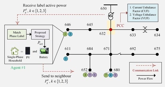
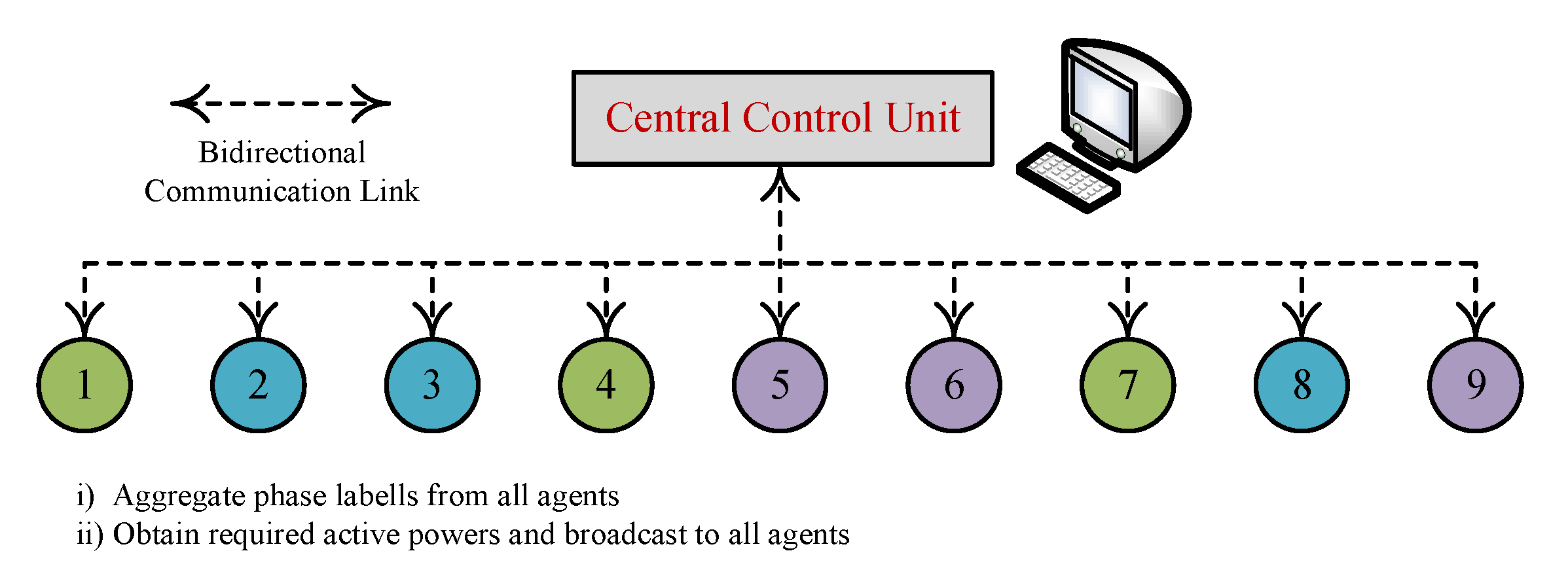
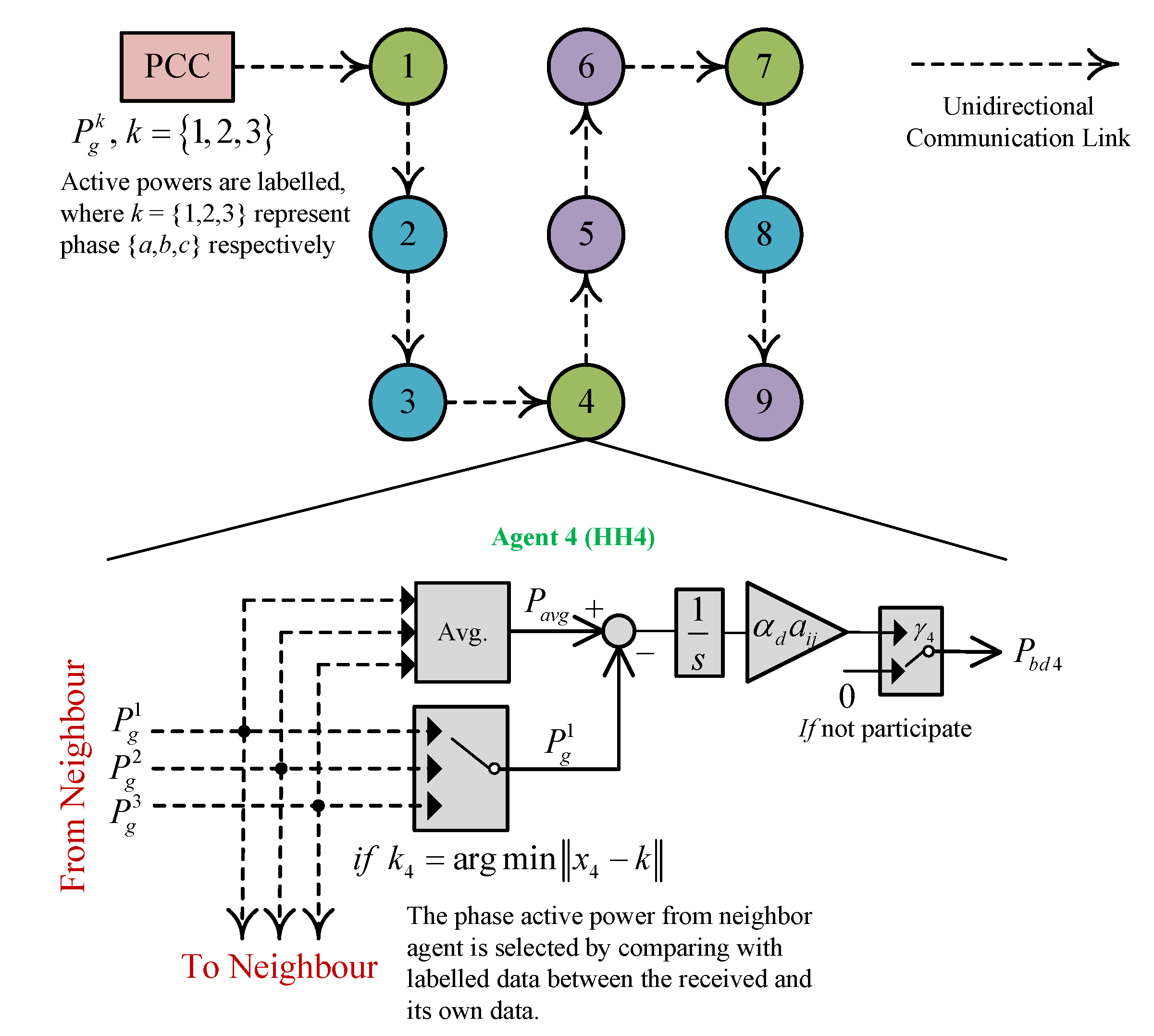
  • A distributed clustering method for labelling was developed. The three-phase active powers at the point of common coupling are labelled with phase labels a, b and c. Then, the values of the labelled active powers are sent to a neighbouring agent in a distributed manner via unidirectional communication network. Subsequently, the agents use the labelled active powers to determine to select its own phase data.
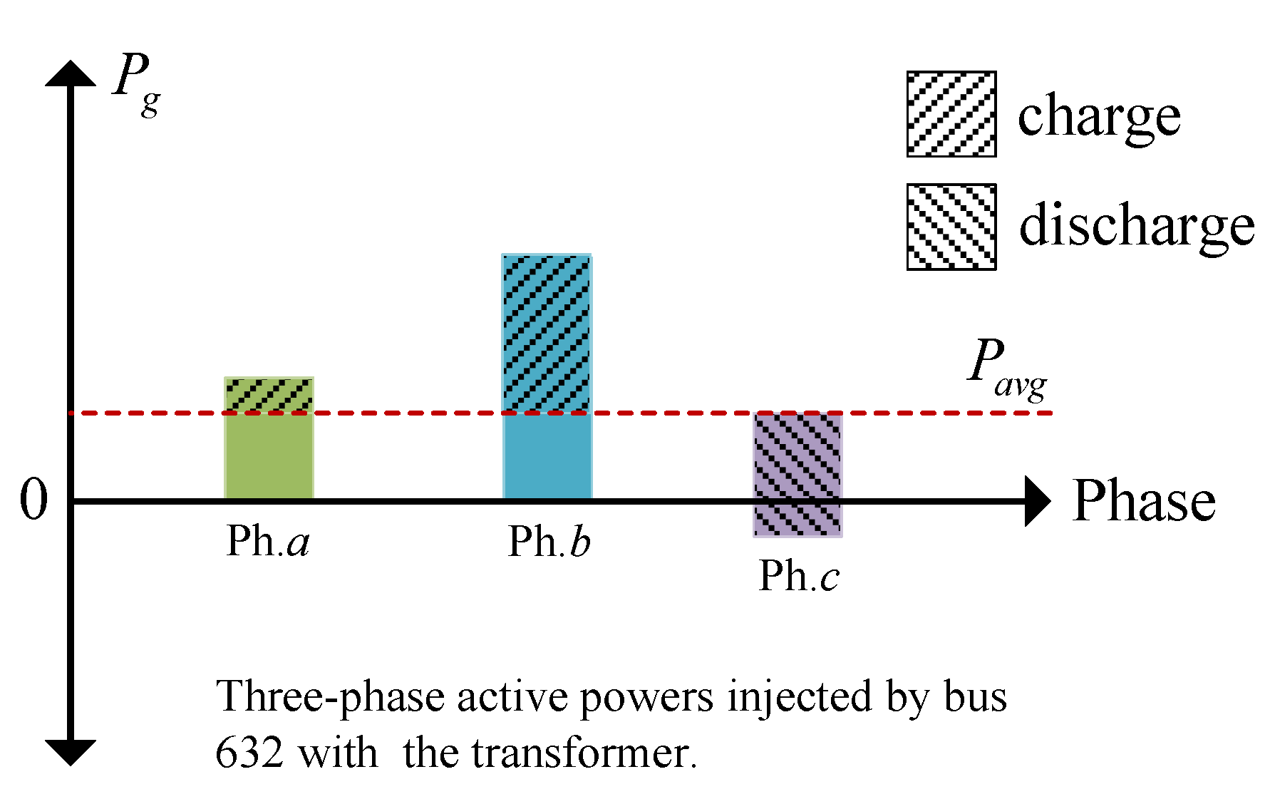
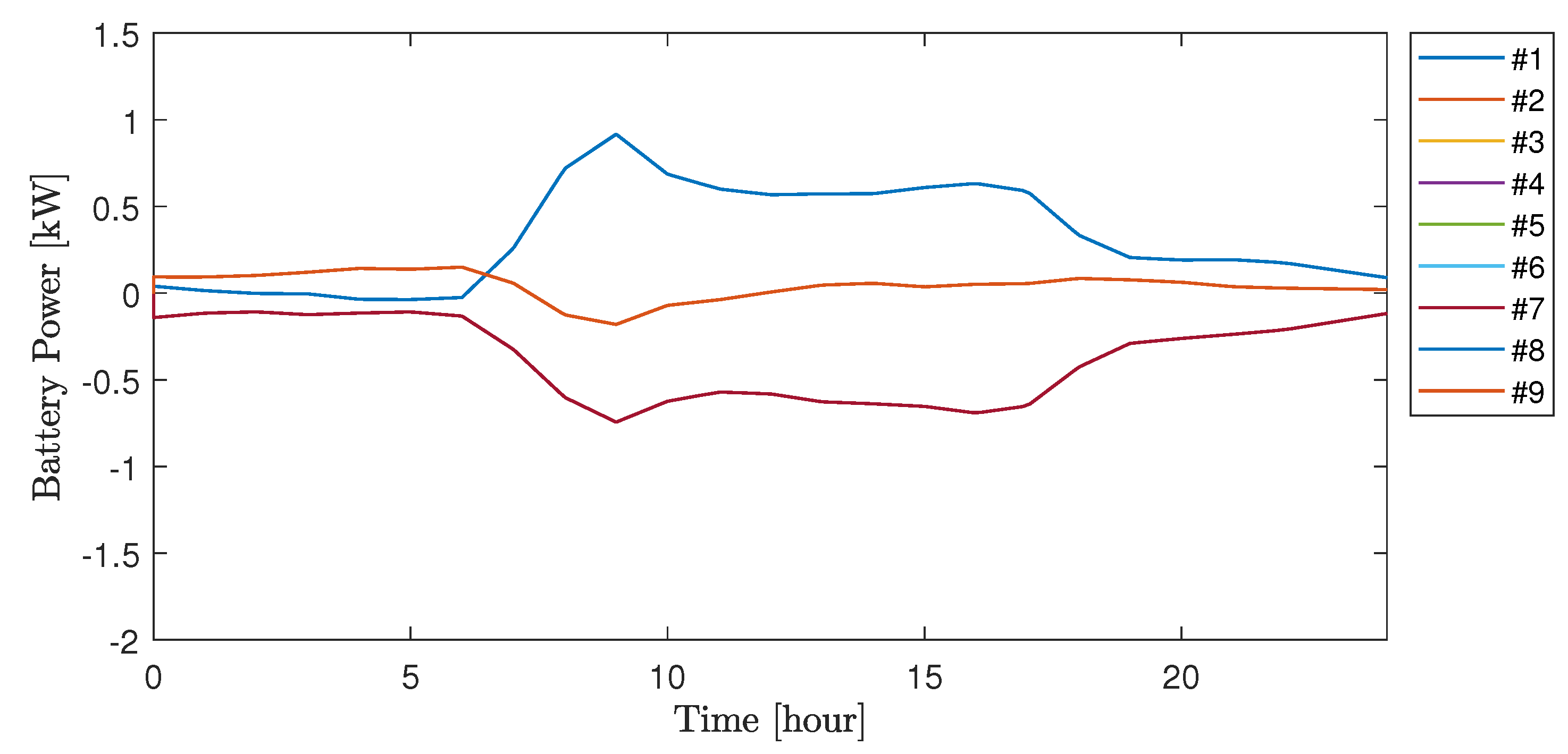
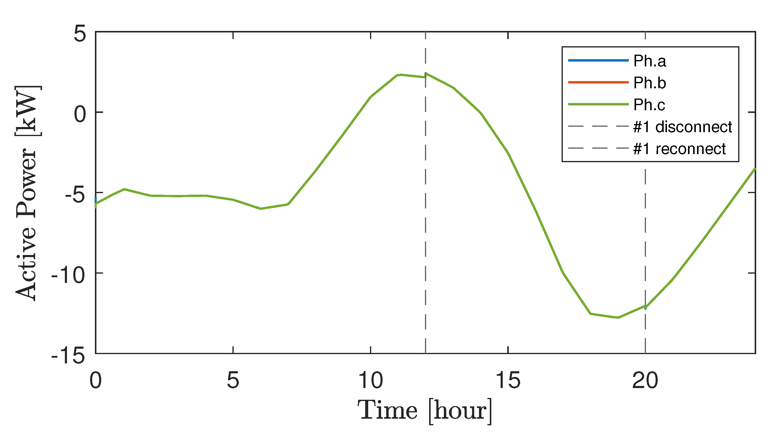
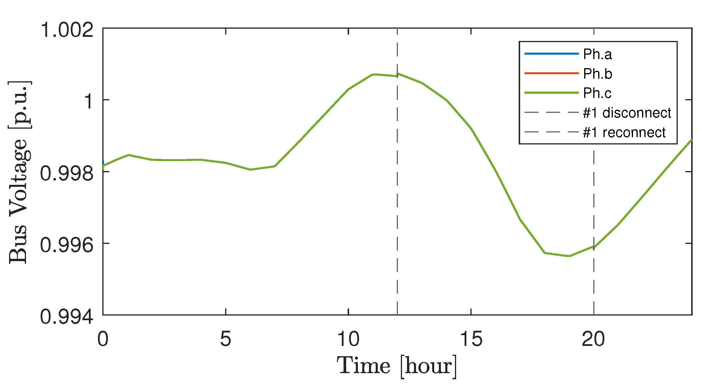
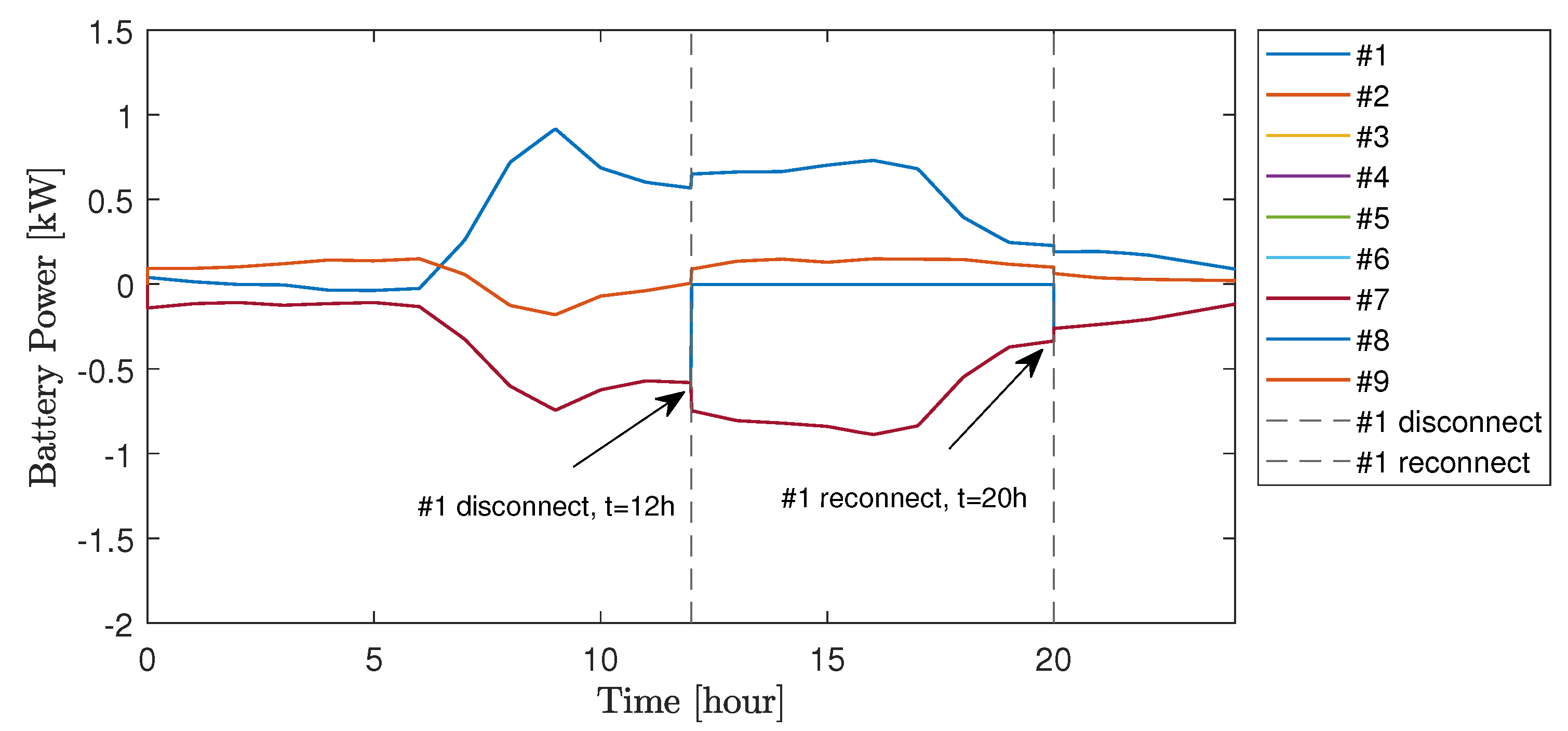
  • Within each agent, the average grid active power is calculated based on information received from the neighbouring agent. Then, using the proposed distributed power balancing control strategy, the battery storage systems cooperatively charge/discharge their active powers to minimize the difference between the average grid power and the phase active power to which they belong. Agents are allowed to disconnect and reconnect without affecting the balancing operation.
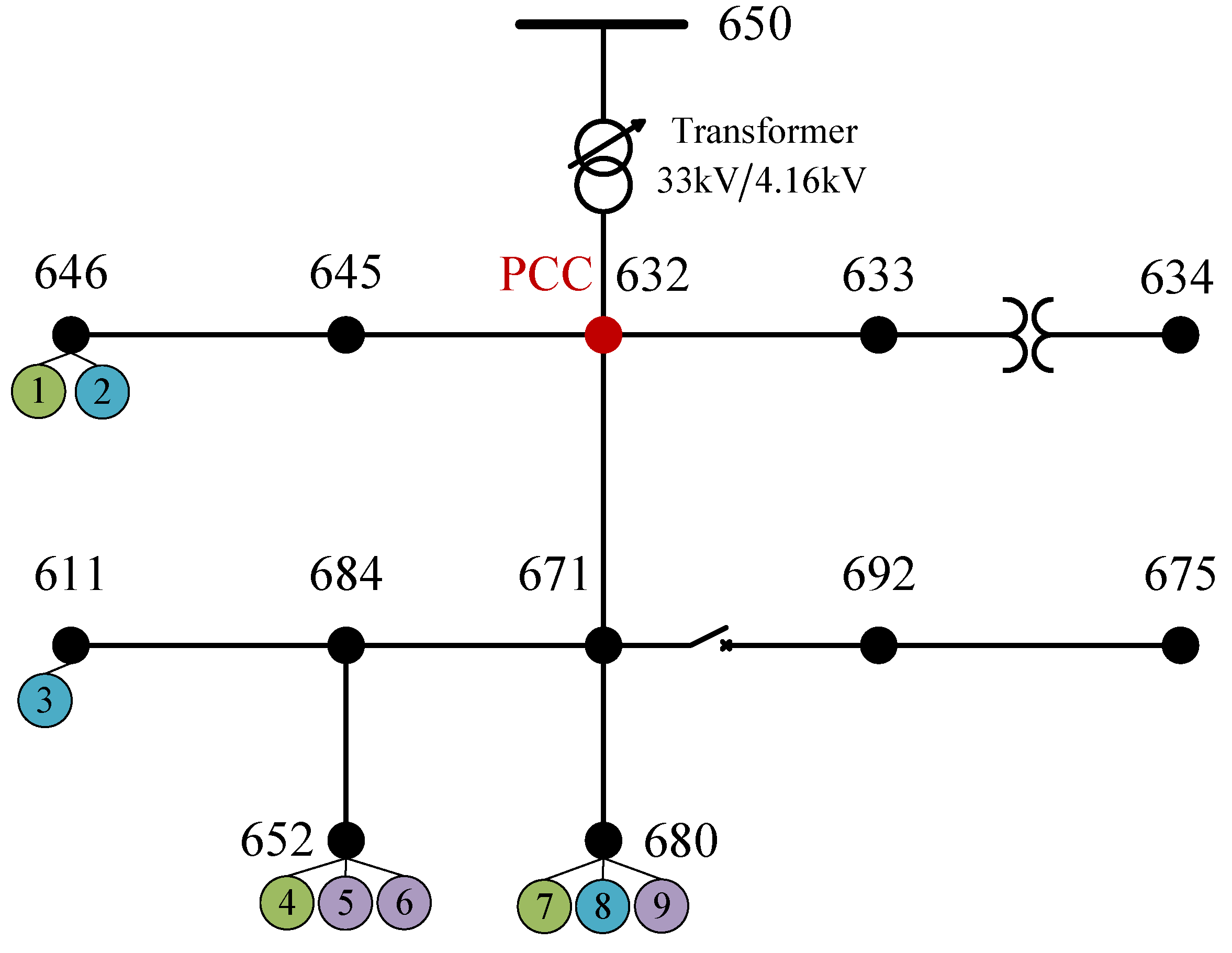
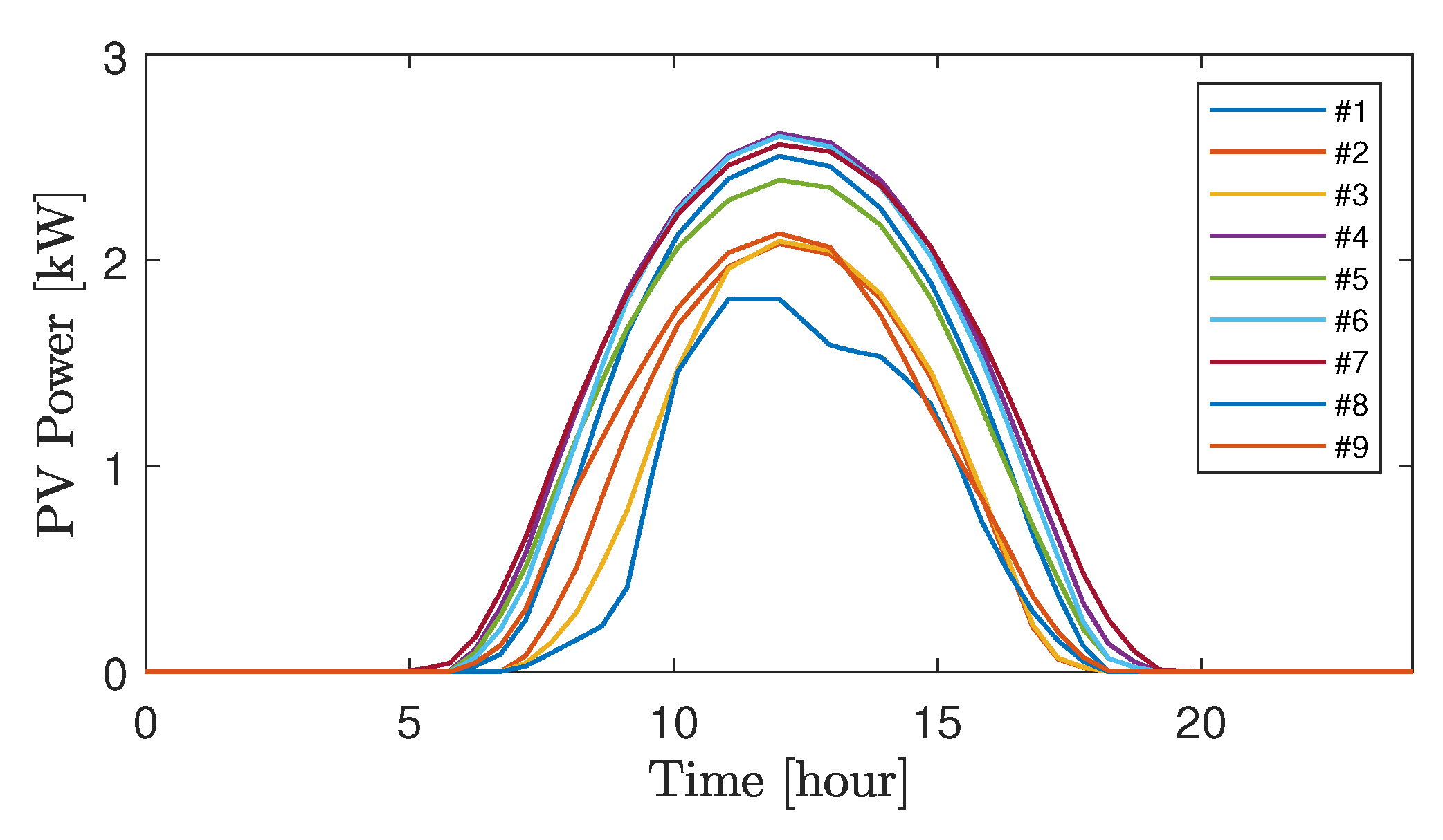
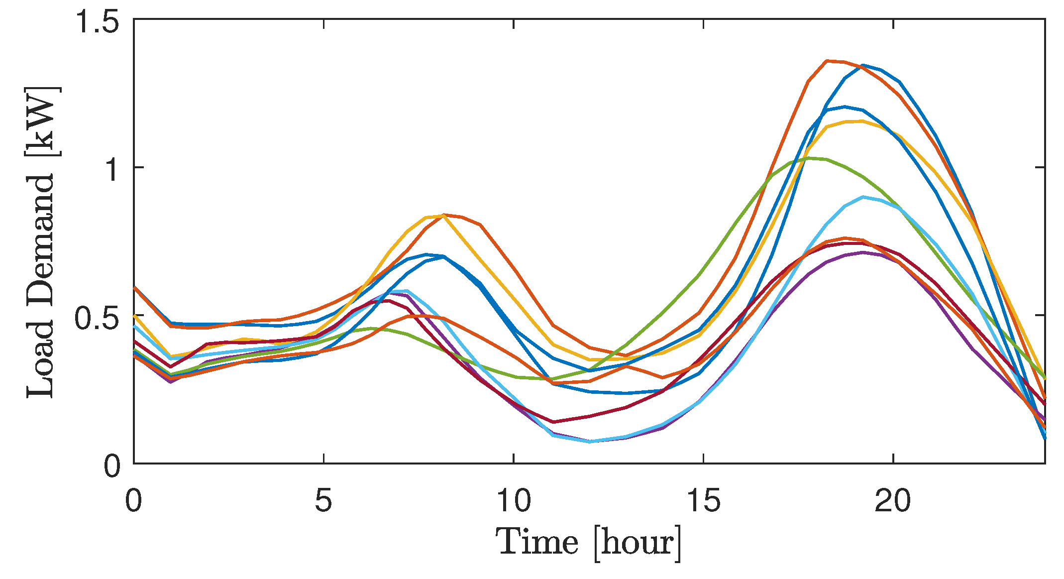
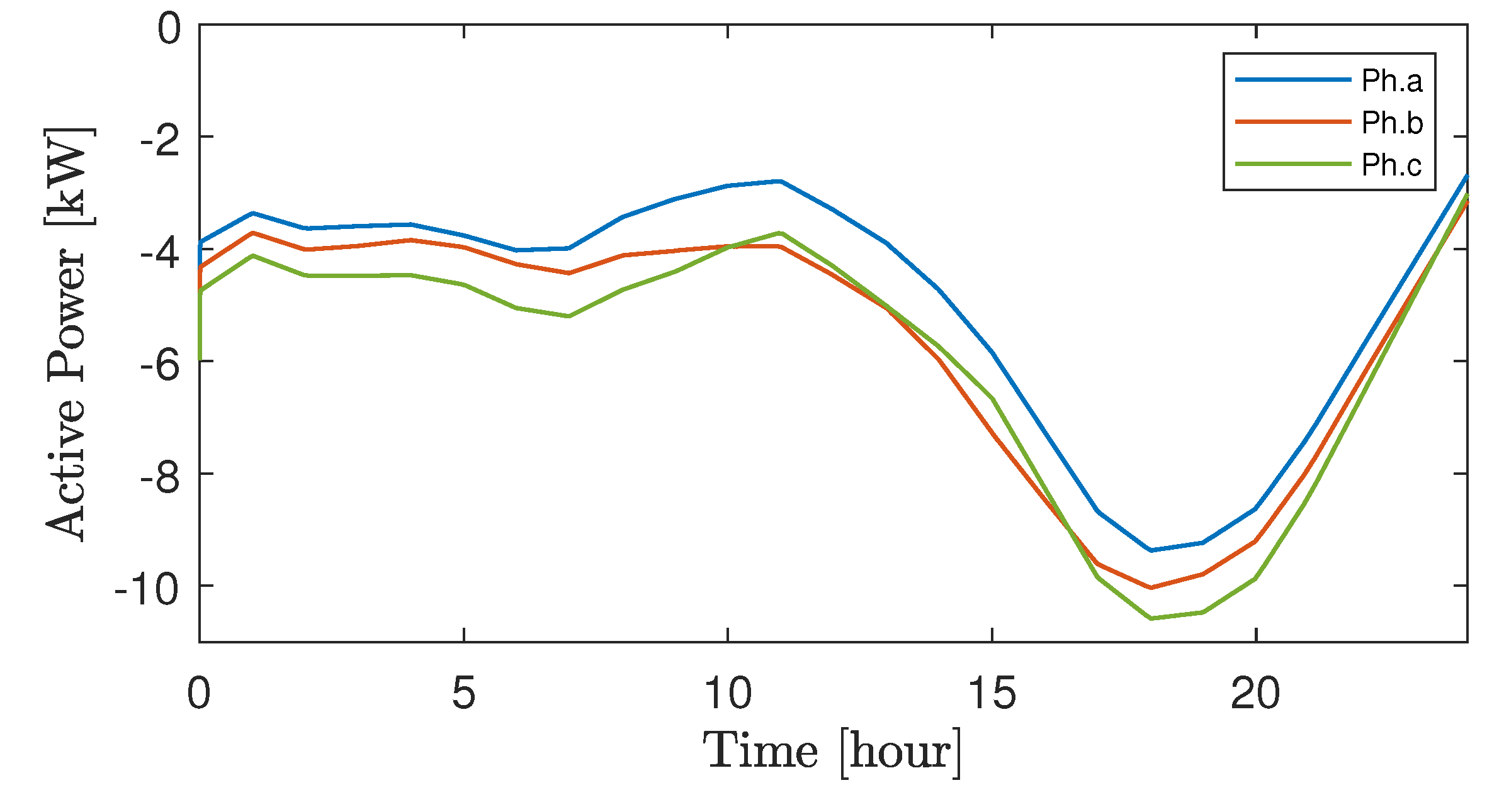
  • Modified IEEE-13-bus test system with real household PV powers and load demand over 24 h are used to verify the performance of the proposed strategy.
The rest of the paper is organized as follows. Section 2 describes the test system used to verify the proposed strategy, it introduces indicators to measure the unbalanced conditions, the constraints on battery storage systems, as well as a local active power control method. Centralized and proposed distributed power balancing control strategies are presented in Section 3. Section 4 verifies the performance of the proposed control strategy using real household PV powers and load demands. Finally, Section 5 concludes the paper.

2. Formulation of Unbalanced Active Power Problem

2.1. System Description

For verification, the IEEE-13-bus test system in [14] is modified with single-phase households equipped with rooftop PV systems, battery storage systems, and load demands, as seen in Figure 1. There is a transformer between the buses 650 and 632 to step-down the voltage level from the main grid from 33 kV to 4.16 kV. It is assumed that single-phase households with battery storage systems are connected to bus numbers 646, 611, 652, and 680, whereas households without battery storage systems are connected to other buses. Schematic diagram of a single-phase household is shown in Figure 2. Also, bus numbers 633 and 634 are three-phase balanced buses. There are nine agents ( N = 9 ) considered in this paper. Each agent is single-phase and consists of a rooftop PV system, a local load and a battery storage system. The capacity of all battery storage systems is selected as 25 kW· h. Connection of the agents is given in Table 2. Real data of household PV powers and load demands over 24 h, taken from [30] are used for each agent, as shown in Figure 3 and Figure 4 respectively.

2.2. Indicators for Measurement of Unbalanced Conditions

In three-phase four-wire power networks, the unbalance factor (UF), considering both negative and zero sequence current components is widely employed to measure voltage and current unbalances caused by high variation and uneven allocation of rooftop PV systems and load demands [1], and is defined as,
UF % = | G n | 2 + | G z | 2 | G p | × 100 , G p G n G z = 1 3 1 a a 2 1 a 2 a 1 1 1 × G a G b G c , ,
where a = e j ( 2 π 3 ) ; G p , G n and G z are positive, negative, and zero sequence components, respectively. The unbalance factor can be represented by the voltage unbalance factor (VUF) or the current unbalance factor (CUF) if G * is replaced by V * or I * . The standard for the voltage unbalance factor that is widely adopted in the literature is less than 2 % .

2.3. Constraints on Battery Storage Systems

In order to achieve good performance of unbalance compensation, all agents are required to participate at all time. However, some agents may have faulty battery systems, or battery constraints have been reached, or the owners may decide not to participate in the control strategy for a period of time. The battery state of charge is one of the constraints that should be considered. The battery state of charge (SoC) can be estimated as,
S o C i ( t ) = S o C i ( 0 ) 1 E b i I b i d t .
Differentiating both sides of Equation (2) gives S o C ˙ i = I b i / E b i . Let V b i be the output voltage of the i-th battery storage system. Then, the output power of the i-th battery storage system can be obtained as P b i = V b i · I b i and the SoC of the i-th battery storage system can be defined as [31],
P b i = V b i · S o C ˙ i · E b i ,
where E b i is the battery capacity (W·s) and P b i the active power of the i-th battery storage system. As it can be seen from Equation (3), the SoC is only a function of the battery output power if the battery voltage V b i is assumed to be constant. For safe operation, the constraints on battery storage systems can be bounded as P b i [ P b i m i n , P b i m a x ] , [ S o C m i n , S o C m a x ] .

2.4. Local Active Power Control Strategy

Typically, a battery storage system is employed to locally compensate for the power mismatch between load demand and renewable generation (rooftop PV). The power exchanged with the grid by the i-th household at phase ϕ is,
P g i ϕ = P b i ϕ + ( P p v i ϕ P l i ϕ ) ,
where P g i ϕ is the power exchanged with the grid; P b i ϕ , P p v i ϕ and P l i ϕ are the battery output power, PV output power, and load demand of the i-th household at phase ϕ , respectively.
As it can be seen from Equation (4), under the normal mode of operation, if the i-th household at phase ϕ has a PV source and a battery storage system, and both are properly sized, the unbalanced power caused by the power mismatch between load and PV generation can be locally compensated by the battery storage system. For example, if P p v i ϕ > P l i ϕ or P p v i ϕ < P l i ϕ the battery system will operate either in charging ( P b i ϕ < 0 ) or discharging ( P b i ϕ > 0 ) mode, and the power exchanged with the grid by the i-th household will be close to zero, P g i ϕ 0 .
However, not all households have battery storage systems. Some households may have only a PV source or no battery system and no PV source. Moreover, the battery storage systems may not be evenly distributed among phases throughout the power system. As a result, there will be the unbalanced phase powers and reverse power flow at some phases at the PCC even if loads are balanced as P g a P g b P g c , and P g ϕ = i = 1 N ϕ P g i ϕ , ϕ { a , b , c } is the total power exchanged with the grid. Therefore, a new and effective strategy for compensating the unbalanced active powers at the PCC is necessary.

3. Active Power Balancing Control Strategy

Figure 5 illustrates a conceptual framework of the active power balancing strategy. Distributed single-phase battery storage systems in the microgrid as shown in Figure 1 can be employed to alleviate the unbalanced conditions. Two control strategies for the compensation are given in this section, (i) centralized and (ii) distributed.

3.1. Centralized Active Power Balancing Strategy

A centralized controller requires that all agents send information to a central control unit, and a fast bidirectional communication system is required. As mentioned earlier, this control strategy may not be attractive due to lack of cost-effectiveness and risk of a single-point of failure. A schematic diagram of the centralized control approach applied for mitigating the unbalanced active powers is shown in Figure 6. The central control unit located at the PCC measures phases active powers and calculates the required active power for the compensation of each phase. Each single-phase battery storage agents sends its phase connection information to the central control unit. Then, the required active power from each agent at each phase can be obtained as,
P b c i ϕ = 1 N ϕ α c ( P a v g P g ϕ ) d t , ϕ { a , b , c } ,
where P b c i ϕ is the required active power from agent i at phase ϕ for the unbalance compensation, N ϕ is the number of agents at each phase that participate in the balancing, α c is the centralized control gain, P a v g = ( P g a + P g b + P g c ) / 3 is the average grid power and P g ϕ is the grid active power at phase ϕ .

3.2. Distributed Active Power Balancing Strategy

The proposed distributed active power balancing strategy employs unidirectional communication between neighbouring agents. In this subsection, preliminaries of a communication graph are introduced.

3.2.1. Communication Graph

A sparse graph, G ( V , E ) represents distributed communication links among neighbours, where V = { 1 , , N } and E denote the nodes (agents or households) and edges respectively. The node, E , has elements ( i , j ) , in which ( i , j ) E if node i can communicate with node j via a communication link [32]. The neighbours of the node i are denoted as N i . Node j is said to be a neighbour of node i if ( i , j ) E . The adjacent matrix of the communication graph is expressed by,
A = [ a i j ] R N × N , a i j = α , ( i , j ) E 0 , otherwise ,
where α denotes the coupling gain.
The graph Laplacian matrix is defined as,
L = D A ,
where D = d i a g { d i } , and the in-degree of the graph is represented as d i = j = 1 N a i j .

3.2.2. Distributed Power Balancing Control Strategy

It is critical for each agent to know information about the active powers at the PCC (both magnitudes and phases). Inspired by supervised machine learning that classifies data based on similar labelled features, the following clustering approach is developed. Let k { 1 , 2 , 3 } be a set of clusters (3-clusters) containing information about the three phases { 1 , 2 , 3 } representing phases a, b and c respectively. Moreover, denote x i , i { 1 , , N } where x i { 1 , 2 , 3 } as locally labelled data for each agent. Hence, the agent i selects its own phase data as,
P g k k -th phase | k i = arg min k { 1 , 2 , 3 } x i k ,
where k i represents the selected phase.
Meanwhile, agent calculates the average grid power based on the active powers received from neighbouring agents as,
P a v g = 1 3 ( P g 1 + P g 2 + P g 3 ) .
Then, based on [32], the battery storage system of the agent i will charge/discharge its active power P b d i to make the active power at its phase is equal to the average grid power as,
P b d i = γ i · α d · a i j ( P a v g P g k ) d t , k { 1 , 2 , 3 } ,
where γ i { 0 , 1 } is the willingness factor for the agent i to participate in the controller ( γ i = 1 means agent agrees to participate, 0 means otherwise), P b d i is the active power of agent i, α d is the distributed control gain, P a v g is the average grid power in Equation (9) and P g k is the grid active power at the k-th phase, where k { 1 , 2 , 3 } . Schematic diagram of the distributed power balancing control strategy is illustrated in Figure 7, while the procedure of the proposed distributed power balancing strategy of agent i is summarized as in Figure 8.

4. Verification Results

The performance of the proposed strategy was verified on a modified IEEE-13-bus test system in Figure 1 with real data of rooftop PV units powers and load demands over 24 h, taken from [30]. Parameters are shown in Table 3. The effectiveness of three control strategies is compared. The first strategy is the local active power control strategy in Equation (4). Only the power mismatch between the PV unit and the load demand is locally compensated within each household; hence, it might fail to achieve the unbalance compensation at the PCC even if the loads are balanced. The second strategy is the centralized controller based on Equation (5). This controller can effectively balance the unbalanced active powers, and is given in order to compare its performance with the proposed distributed control strategy. The third strategy is the proposed distributed control strategy based on Equation (10). The agent can only communicate with its neighbours via a unidirectional communication system.

4.1. Local Power Balancing Control Strategy

A local active power controller, given in Equation (4), is applied to illustrate that it fails to compensate the unbalanced conditions in the system. The power mismatch of each agent is locally compensated within the household, and no powers are consumed/injected from/to the grid ( P g i ϕ 0 ). As a consequence, the active powers flowing from bus 632 to the transformer are always negative and the loads are supplied by importing the active powers from the grid. The unbalanced active powers and voltages are shown in Figure 9 and Figure 10, respectively. Batteries active powers of the local control strategy is depicted in Figure 11. These unbalanced conditions are caused by uneven allocation of PV units and loads.

4.2. Centralized Power Balancing Control Strategy

In this control strategy, bidirectional communication links are required between agents and the central control unit. All agents that participate in the controller send information about the phase to the control unit, and then the control unit sends the required active powers back to each agent based on Equation (6). Hence, the unbalanced active powers and voltages at the PCC can be alleviated as it can be seen in Figure 12 and Figure 13, respectively. Batteries active powers of the centralized control strategy can be seen in Figure 14.

4.3. Distributed Power Balancing Control Strategy

This strategy only required unidirectional communication links between agents and labelled data of active powers of each phase at the PCC. As it can be seen in Figure 15 and Figure 16, the active powers of each phase exchanged by bus 623 with the transformer and the phase voltages at the bus are balanced. The results are similar to the results obtained by the centralized control strategy in Figure 12 and Figure 13, respectively. However, in the proposed control scheme, the active power required for the unbalanced compensation is calculated by the agent (single-phase household) as illustrated in Figure 8. The agent can decide whether to participate in the control scheme without affecting the power balancing operation. Batteries active powers during the balancing can be seen in Figure 17.
Furthermore, during the balancing operation, at t = 12.00 , h agent-1 is not willing to participate in the control strategy ( γ i = 0 ), so it contributes zero active power. At t = 20.00 h, the agent-1 is reconnected ( γ i = 1 ) and starts contributing the same active powers as the other agents at the same phase. During the disconnection and reconnection of the agent-1, the active powers and bus voltages are still maintained/balanced, even though there is some transient response at t = 12.00 h and t = 20.00 h.

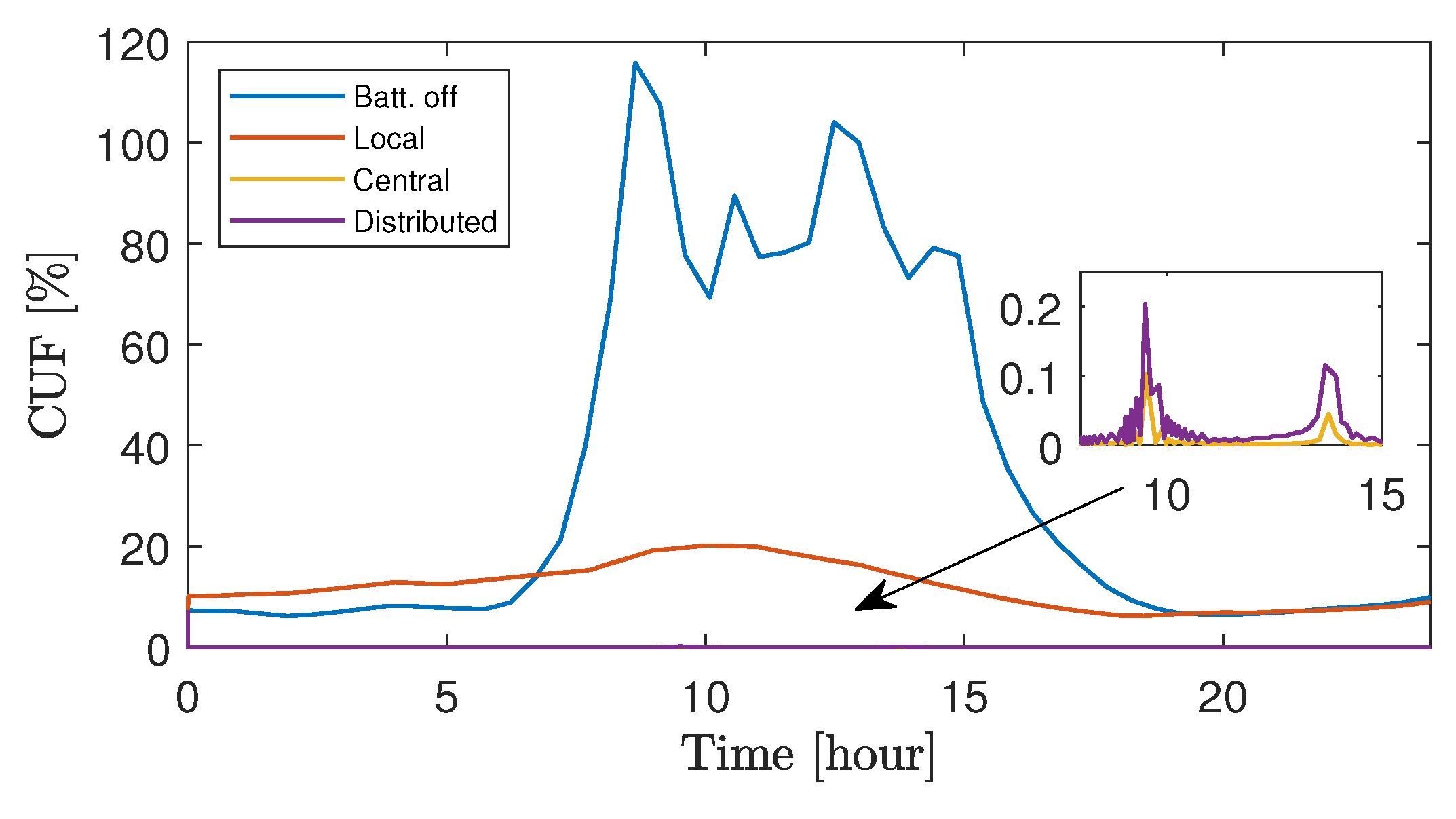
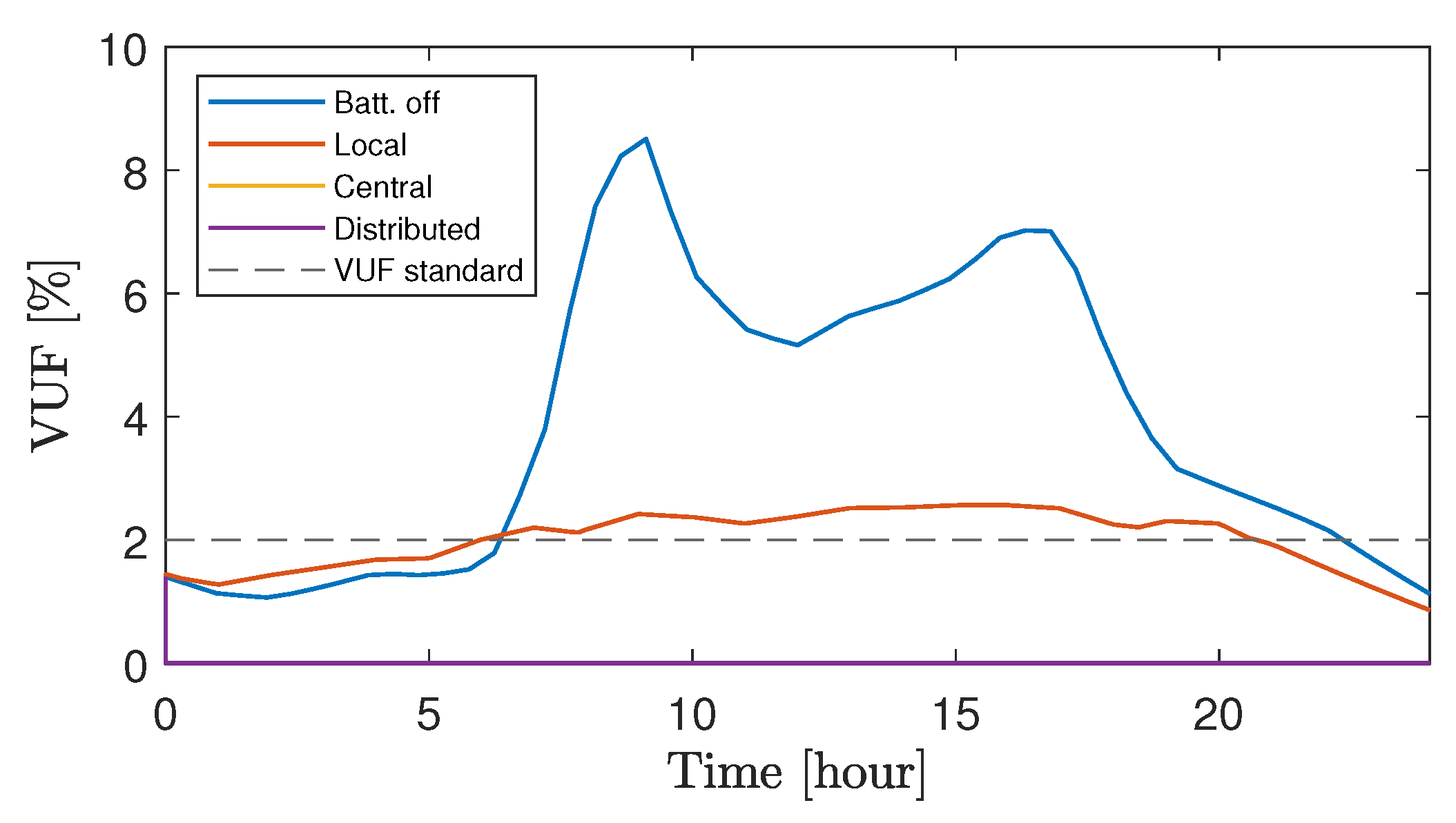
4.4. Comparison of Balancing Control Strategies

The unbalance factor in Equation (1) is adopted to quantify the unbalanced conditions. Two widely used unbalance factors are used in this subsection: the current unbalance factor (CUF) and the voltage unbalance factor (VUF). Figure 18 shows the current unbalance factor during operation. As it can be seen, the highest CUF is when the battery storage systems of all agents are switched-off (batt. off). The CUF obtained by the local power balancing control strategy denoted as local is decreased, but it is still greater than 20 % . On the contrary, the CUFs for the central and distributed control strategies are substantially reduced to less than 0.5 % .
Similarly, the VUF, when all battery storage systems are switched-off (Batt. off), is the highest. Meanwhile, the VUF obtained by the Local power balancing control strategy is decreased, but it is still higher than the standard (VUF < 2 % ) [1] during midday as shown in Figure 19. However, the VUFs for the Central and distributed control strategies are significantly decreased to around 2 % .

5. Conclusions

This paper presented a distributed control strategy to alleviate the unbalanced active powers, caused by high penetration and uneven allocation of PV rooftop systems and loads, using single-phase battery storage systems distributed in a three-phase four-wire microgrid. First, the three-phase active powers at the PCC were phase labelled and then the labelled powers were sent to agents in a distributed manner via unidirectional communication links. Within each agent, the labelled power data were compared with the agent data, to select its own phase active power. Furthermore, the average grid power was obtained and then the proposed distributed power balancing control strategy was applied. The battery storage systems were cooperatively operated to minimize the difference between the phase active power and the average power so that the active powers at the PCC become balanced. The battery’s owner can decide not to participate in the control strategy for a period of time due to violation of battery constraints or for other reasons. The effectiveness of the proposed strategy was verified on the modified IEEE-13-bus test system with real-time data of rooftop PV systems and load demands.
Further work will focus on developing a method for partitioning a large-scale power system into smaller sub-systems based on geographical location, and applying the proposed distributed power balancing control strategy for compensation of unbalanced active powers in each sub-system.

Author Contributions

Conceptualization, W.P. and B.H.; methodology, W.P. and B.H.; simulation, W.P.; validation, W.P. and B.H.; visualization, W.P.; formal analysis, W.P.; writing—original draft preparation, W.P.; writing—review and editing, W.P. and B.H.; supervision, B.H. All authors have read and agreed to the published version of the manuscript.

Funding

This research received no external funding.

Institutional Review Board Statement

Not applicable.

Informed Consent Statement

Not applicable.

Data Availability Statement

Not applicable.

Acknowledgments

W.P. gratefully acknowledges the scholarship from the Ministry of Higher Education, Science, Research, and Innovation, Thailand.

Conflicts of Interest

The authors declare no conflict of interest.

References

  1. Rafi, F.H.M.; Hossain, M.; Rahman, M.S.; Taghizadeh, S. An overview of unbalance compensation techniques using power electronic converters for active distribution systems with renewable generation. Renew. Sustain. Energy Rev. 2020, 125, 109812. [Google Scholar] [CrossRef]
  2. Von Jouanne, A.; Banerjee, B. Assessment of voltage unbalance. IEEE Trans. Power Deliv. 2001, 16, 782–790. [Google Scholar] [CrossRef]
  3. Castilla, M.; Miret, J.; Camacho, A.; Matas, J.; García de Vicuña, L. Voltage Support Control Strategies for Static Synchronous Compensators Under Unbalanced Voltage Sags. IEEE Trans. Ind. Electron. 2014, 61, 808–820. [Google Scholar] [CrossRef]
  4. Yunus, K.; De La Parra, H.Z.; Reza, M. Distribution grid impact of plug-in electric vehicles charging at fast charging stations using stochastic charging model. In Proceedings of the 2011 14th European Conference on Power Electronics and Applications, Birmingham, UK, 30 August–1 September 2011; pp. 1–11. [Google Scholar]
  5. Shahnia, F.; Wolfs, P.J.; Ghosh, A. Voltage unbalance reduction in low voltage feeders by dynamic switching of residential customers among three phases. IEEE Trans. Smart Grid 2014, 5, 1318–1327. [Google Scholar] [CrossRef] [Green Version]
  6. Wu, P.H.; Chen, H.C.; Chang, Y.T.; Cheng, P.T. Delta-Connected Cascaded H-Bridge Converter Application in Unbalanced Load Compensation. IEEE Trans. Ind. Appl. 2017, 53, 1254–1262. [Google Scholar] [CrossRef]
  7. Lefcourt, A. Effects of Electrical Voltage/Current on Farm Animals: How to Detect and Remedy Problems. Agriculture Handbook; Technical Report; Agricultural Research Service: Albany, CA, USA, 1991.
  8. Surbrook, T.C.; Reese, N.D.; Kehrle, A.M. Stray Voltage: Sources and Solutions. IEEE Trans. Ind. Appl. 1986, IA-22, 210–215. [Google Scholar] [CrossRef]
  9. Zhu, J.; Chow, M.Y.; Zhang, F. Phase balancing using mixed-integer programming [distribution feeders]. IEEE Trans. Power Syst. 1998, 13, 1487–1492. [Google Scholar] [CrossRef]
  10. Hsu, Y.Y.; Yi, J.H.; Liu, S.; Chen, Y.; Feng, H.; Lee, Y. Transformer and feeder load balancing using a heuristic search approach. IEEE Trans. Power Syst. 1993, 8, 184–190. [Google Scholar] [CrossRef]
  11. Zeraati, M.; Golshan, M.E.H.; Guerrero, J.M. Voltage Quality Improvement in Low Voltage Distribution Networks Using Reactive Power Capability of Single-Phase PV Inverters. IEEE Trans. Smart Grid 2019, 10, 5057–5065. [Google Scholar] [CrossRef]
  12. Rafi, F.H.M.; Hossain, M.J.; Lu, J. Improved Neutral Current Compensation with a Four-Leg PV Smart VSI in a LV Residential Network. IEEE Trans. Power Deliv. 2017, 32, 2291–2302. [Google Scholar] [CrossRef]
  13. Md Rafi, F.H.; Hossain, M.J.; Town, G.; Lu, J. Smart Voltage-Source Inverters with a Novel Approach to Enhance Neutral-Current Compensation. IEEE Trans. Ind. Electron. 2019, 66, 3518–3529. [Google Scholar] [CrossRef]
  14. Yao, M.; Hiskens, I.A.; Mathieu, J.L. Mitigating Voltage Unbalance Using Distributed Solar Photovoltaic Inverters. IEEE Trans. Power Syst. 2021, 36, 2642–2651. [Google Scholar] [CrossRef]
  15. Nejabatkhah, F.; Li, Y.W. Flexible Unbalanced Compensation of Three-Phase Distribution System Using Single-Phase Distributed Generation Inverters. IEEE Trans. Smart Grid 2019, 10, 1845–1857. [Google Scholar] [CrossRef]
  16. Neukirchner, L.; Görbe, P.; Magyar, A. Voltage unbalance reduction in the domestic distribution area using asymmetric inverters. J. Clean. Prod. 2017, 142, 1710–1720. [Google Scholar] [CrossRef]
  17. Jabalameli, N.; Su, X.; Ghosh, A. Online centralized charging coordination of PEVs with decentralized var discharging for mitigation of voltage unbalance. IEEE Power Energy Technol. Syst. J. 2019, 6, 152–161. [Google Scholar] [CrossRef]
  18. Zeraati, M.; Hamedani Golshan, M.E.; Guerrero, J.M. A Consensus-Based Cooperative Control of PEV Battery and PV Active Power Curtailment for Voltage Regulation in Distribution Networks. IEEE Trans. Smart Grid 2019, 10, 670–680. [Google Scholar] [CrossRef] [Green Version]
  19. Akhavan-Rezai, E.; Shaaban, M.F.; El-Saadany, E.F.; Karray, F. Managing demand for plug-in electric vehicles in unbalanced LV systems with photovoltaics. IEEE Trans. Ind. Inform. 2017, 13, 1057–1067. [Google Scholar] [CrossRef]
  20. Hernández, J.C.; Langella, R.; Cano, A.; Testa, A. Unbalance characteristics of fundamental and harmonic currents of three-phase electric vehicle battery chargers. IET Gener. Transm. Distrib. 2020, 14, 6220–6229. [Google Scholar] [CrossRef]
  21. Alam, M.J.E.; Muttaqi, K.M.; Sutanto, D. Community energy storage for neutral voltage rise mitigation in four-wire multigrounded LV feeders with unbalanced solar PV allocation. IEEE Trans. Smart Grid 2015, 6, 2845–2855. [Google Scholar] [CrossRef] [Green Version]
  22. Alam, M.J.E.; Muttaqi, K.M.; Sutanto, D. Alleviation of neutral-to-ground potential rise under unbalanced allocation of rooftop PV using distributed energy storage. IEEE Trans. Sustain. Energy 2015, 6, 889–898. [Google Scholar] [CrossRef] [Green Version]
  23. Bozalakov, D.V.; Mnati, M.J.; Laveyne, J.; Van den Bossche, A.; Vandevelde, L. Voltage unbalance and overvoltage mitigation by using the three-phase damping control strategy in battery storage applications. In Proceedings of the 2018 7th International Conference on Renewable Energy Research and Applications (ICRERA), Paris, France, 14–17 October 2018; pp. 753–759. [Google Scholar]
  24. Wong, J.; Lim, Y.S.; Morris, S.; Morris, E.; Chua, K.H. Fuzzy-driven energy storage system for mitigating voltage unbalance factor on distribution network with photovoltaic system. AIP Conf. Proc. 2017, 1828, 020019. [Google Scholar]
  25. Ferreira, D.M.; Brandao, D.I.; Bergna-Diaz, G.; Tedeschi, E.; Silva, S.M. Distributed Control Strategy for Low-Voltage Three-Phase Four-Wire Microgrids: Consensus Power-Based Control. IEEE Trans. Smart Grid 2021, 12, 3215–3231. [Google Scholar] [CrossRef]
  26. Yu, S.S.; Chu, S.W.; Wang, C.M.; Chan, Y.K.; Chang, T.C. Two improved k-means algorithms. Appl. Soft Comput. 2018, 68, 747–755. [Google Scholar] [CrossRef]
  27. Geva, A.B. Hierarchical unsupervised fuzzy clustering. IEEE Trans. Fuzzy Syst. 1999, 7, 723–733. [Google Scholar] [CrossRef]
  28. Flanagan, J.A. Self-organisation in Kohonen’s SOM. Neural Netw. 1996, 9, 1185–1197. [Google Scholar] [CrossRef]
  29. Aci, M.; Avci, M. K nearest neighbor reinforced expectation maximization method. Expert Syst. Appl. 2011, 38, 12585–12591. [Google Scholar] [CrossRef]
  30. Sharma, V.; Haque, M.H.; Aziz, S.M. PV generation and load profile data of net zero energy homes in South Australia. Data Brief 2019, 25, 104235. [Google Scholar] [CrossRef] [PubMed]
  31. Pinthurat, W.; Hredzak, B. Decentralized Frequency Control of Battery Energy Storage Systems Distributed in Isolated Microgrid. Energies 2020, 13, 3026. [Google Scholar] [CrossRef]
  32. Lewis, F.L.; Zhang, H.; Hengster-Movric, K.; Das, A. Cooperative Control of Multi-Agent Systems: Optimal and Adaptive Design Approaches; Springer Science & Business Media: Berlin/Heidelberg, Germany, 2013. [Google Scholar]
Figure 1. Modified IEEE-13-bus test system.
Energies 14 08287 g001
Figure 2. Illustrative example of agent i (single-phase household). During the normal mode of operation, the rooftop PV unit is operated at maximum power and the battery storage system can operate in either the charging or discharging mode to compensate the power mismatch between PV generation and load demand.
Energies 14 08287 g002
Figure 3. PV powers of all agents over 24 h.
Energies 14 08287 g003
Figure 4. Load demands of all agents over 24 h.
Energies 14 08287 g004
Figure 5. Conceptual framework of the active power balancing control strategy. The active powers in all three phases are balanced by adjusting them to be equal to the average grid power P a v g using single-phase battery storage systems distributed in the microgrid.
Energies 14 08287 g005
Figure 6. Schematic diagram of the centralized power balancing control strategy. The central control unit aggregates agents of each phase. Then, it calculates and broadcasts to all agents how much active power is required from each of them to compensate the unbalanced active powers. Bidirectional communication links are required.
Energies 14 08287 g006
Figure 7. Schematic diagram of the distributed power balancing control strategy. Active powers exchanged by bus 623 with the transformer are first labelled with the value of the active power and the phase. Then, each agent receives the labelled powers, and passes them to the neighbouring agent via unidirectional communication links. Within each agent, the average grid power, P a v g is obtained and the agent selects the participating phase by comparing its label with the labelled grid powers. Finally, the agent adjusts its active powers according to the obtained average power, and decides whether to contribute by setting the willingness factor, γ i .
Energies 14 08287 g007
Figure 8. Distributed power balancing control strategy for the i-th agent (single-phase household). The distributed communication is represented by the dashed red lines.
Energies 14 08287 g008
Figure 9. Active powers exchanged by bus 632 at PCC with the transformer using the local active power control strategy.
Energies 14 08287 g009
Figure 10. Bus voltages at bus 623 at PCC using the local active power control strategy.
Energies 14 08287 g010
Figure 11. Batteries active powers of all agents during the balancing operation using the local control strategy.
Energies 14 08287 g011
Figure 12. Active powers exchanged by bus 632 at PCC with the transformer using the centralized control strategy.
Energies 14 08287 g012
Figure 13. Bus voltages at bus 623 at PCC using the centralized control strategy.
Energies 14 08287 g013
Figure 14. Batteries active powers of all agents during the balancing operation using the centralized control strategy.
Energies 14 08287 g014
Figure 15. Active powers exchanged by bus 632 at PCC with the transformer using the proposed distributed control strategy.
Energies 14 08287 g015
Figure 16. Bus voltages at bus 623 at PCC using the proposed distributed control strategy.
Energies 14 08287 g016
Figure 17. Batteries active powers of all agents during the balancing operation. It can been observed that the battery storage systems belonging to the same phase contributed the same amount of active power. At time t = 12.00 h to t = 20.00 h, the agent-1 is disconnected and contributes zero active power. After the agent-1 is reconnected it starts sharing the same active power as the other agents at the phase.
Energies 14 08287 g017
Figure 18. Comparison of the current unbalance factor for different control strategies. Batt. off, local, central, and distributed correspond to battery switched-off, local power controller, centralized power controller, and distributed power controller, respectively. The inset figure shows the difference between the central and distributed controllers.
Energies 14 08287 g018
Figure 19. Comparison of the voltage unbalance factor for different control strategies. Batt. off, local, central, and distributed correspond to battery switched-off, local power controller, centralized power controller, and distributed power controller, respectively.
Energies 14 08287 g019
Table 1. Comparison of techniques for compensation of unbalanced conditions.
Ref.ConverterEVDESCESCentralizedDecentralizedDistributedVUFCUF1-ϕTest System
[13]🗸 🗸 🗸 Real-44-bus
[14]🗸 🗸🗸 🗸IEEE-13-bus
[15]🗸 🗸 🗸IEEE-13-bus
[16]🗸 🗸 Simplified
[17] 🗸 🗸🗸 🗸 Real-74-bus
[18] 🗸 🗸🗸 IEEE European
[19] 🗸 🗸 🗸 IEEE-123-bus
[20] 🗸 🗸 🗸 Simplified
[21] 🗸🗸 🗸 Australian DS
[22] 🗸 🗸 🗸🗸Australian DS
[23] 🗸 🗸 🗸 Simplified
[24] 🗸 🗸 🗸 Simplified
Our 🗸 🗸🗸🗸🗸IEEE-13-bus
Table 2. Locations of distributed single-phase battery systems.
Agent123456789
Bus646646611652652652680680680
Phaseabbaccabc
Table 3. Case study parameters.
ParameterSymbolValue
Number of agentsN9
Microgrid voltage level V m g 4.16 kV-LL (1.0 p.u.)
Battery capacity E b i 25 kW·h
Coupling gain α 1
Centralized control gain α c 1.5 × 10 3
Distributed control gain α d 1.425 × 10 4
Willingness factor γ i { 0 , 1 }
Publisher’s Note: MDPI stays neutral with regard to jurisdictional claims in published maps and institutional affiliations.

