Article

Performance Evaluation of a Maisotsenko Cycle Cooling Tower with Uneven Length of Dry and Wet Channels in Hot and Humid Conditions

1
Key Laboratory of Low-Grade Energy Utilization Technologies and Systems, Ministry of Education of China, Chongqing University, Chongqing 400044, China
2
Yuanda Environmental Protection Science & Technology Branch, State Power Investment Corporation (SPIC), Chongqing 400012, China
*
Author to whom correspondence should be addressed.
Energies 2021, 14(24), 8249; https://doi.org/10.3390/en14248249
Submission received: 15 October 2021 / Revised: 3 November 2021 / Accepted: 10 November 2021 / Published: 8 December 2021
(This article belongs to the Special Issue Research and Development on Indirect Evaporative Cooling Technology)

Abstract

:
The use of the Maisotsenko cycle (M-Cycle) in traditional wet cooling towers (TWCTs) has the potential to reduce the costs of electricity generation by cooling water below the inlet air’s wet-bulb temperature. TWCTs cannot provide sufficient cooling capacity for the increasing demand for cooling energy in the power and industrial sectors—especially in hot and wet climates. Due to this fact, an experimental system of an M-Cycle cooling tower (MCT) with parallel counter-flow arrangement fills was constructed in order to provide perspective on the optimal length of dry channels (ldry), thermal performance under different conditions, and pressure drops of the MCT. Results showed that the optimal value of ldry was 2.4 m, and the maximum wet-bulb effectiveness was up to 180%. In addition, the impact of air velocity in wet channels on the pressure drops of the novel fills was also summarized. This study confirms the great potential of using the M-Cycle in TWCTs, and provides a guideline for the industrial application and performance improvement of MCTs.

1. Introduction

The traditional wet cooling tower (TWCT) is considered to be one of the key components of electricity generation systems, as well as an important factor affecting the total efficiency of thermal power plants [1,2]. TWCTs are used to decrease the temperature of cooling water, before it can be sent to a condenser for conversion of the exhaust steam discharged by the steam turbine into water [3]. Efficient operation of TWCTs is determined by the outlet water temperature. In Rankine-cycle-based thermal power plants, the coal consumption decreases and the thermal efficiency increases with the decrease in the outlet water temperature of the cooling towers [4,5]. It is therefore necessary to improve the thermal performance of TWCTs.
Methods for improving the thermal performance of TWCTs have been proposed by many authors in the past. Chen et al. [6,7] suggested that installing air ducts in the rain area could improve the aerodynamic field of the tower and alleviate the adverse crosswind effect, so as to significantly improve the performance of TWCTs. Structural improvement measures—including adding air deflectors, using non-uniform fillings, and adding air ducts—were also implemented in one large-scale TWCT in order to weaken the adverse influence of crosswind [8]. However, the outlet water temperature of TWCTs remained limited by the inlet air’s wet-bulb temperature, which is a major disadvantage, despite many useful methods having been proposed [9,10,11]. Due to this fact, TWCTs cannot provide cooling water with a sufficiently low temperature to meet the increasing demand for cooling energy in the power and industrial sectors—especially in hot and humid conditions. It is therefore crucial to find alternative approaches to overcome this limit and further decrease the outlet water temperature.
The Maisotsenko cycle, also known as the M-Cycle [12], provides a solution to reduce the amount of process fluid approaching the inlet air’s dew-point temperature, which is always lower than its wet-bulb temperature in most climates [13]. The M-Cycle’s feasibility has been proven by many studies, and it is often used in air cooling for different purposes, such as providing thermal comfort, pre-cooling of compressor inlet air, conditioning of data centers, etc. [14,15,16,17,18,19]. If the application of the M-Cycle in TWCTs can cool the water approaching the inlet air’s dew-point temperature, it may be one of the most useful methods to improve the thermal performance of TWCTs. The analysis conducted in [20] showed that USD 950,000 could be saved if the temperature of the cooling water provided for a 600 MW power plant was 5 °C lower than the current standard. For instance, the difference between the wet-bulb and dew-point temperatures is up to ~8 °C under the conditions of a dry-bulb temperature of 40 °C and a humidity ratio of 10 g/kg, which means that there is significant potential for the application of the M-Cycle in TWCTs.
However, few studies have discussed the subject of M-Cycle cooling towers (MCTs). Gillan et al. [21] proposed the basic conception of two types of MCT: the open-circuit MCT, and the closed-circuit MCT. Morosuk et al. [22,23] investigated the exergetic analysis and the coefficient of performance (COP) of MCTs. Although their work proved that MCTs could reduce the water temperature below the inlet air’s wet-bulb temperature, it was still a challenge to design MCTs with complicated fills and confirm the real possibility of MCTs in laboratory tests [24]. The EPRI (Electric Power Research Institute) [25] conducted a complicated feasibility demonstration in the laboratory and greatly promoted the technological development of MCTs; however, the advanced fills with cross-counter-flow arrangement proposed by the EPRI were very hard to apply in TWCTs. Fills with parallel counter-flow arrangement were numerically studied by Pandelidis et al. [26,27], and the advantage of fills with uneven lengths of dry and wet channels was confirmed; however, the optimal length of dry channels, which directly affect the thermal performance and resistance characteristics of MCTs, was not investigated in detail.
With the constantly growing need for effective heat rejection methods in almost all market sectors, it is important to analyze and overcome the main challenges of MCTs, including the geometry of the MCTs, the optimal length of dry channels, and pressure drops in fills. Therefore, an experimental system of an MCT with parallel counter-flow arrangement fills was constructed in the present study, in order to gain perspective on the optimal length of dry channels, thermal performance under different conditions, and pressure drops of MCTs. The calculation method of the number of heat transfer units of primary air (NTU1) was proposed, and the relationship between NTU1 and the length of dry channels (ldry) was discussed. The effects of structural (including ldry and NTU1) and operational (including inlet air temperature and humidity ratio, inlet water temperature, and heat capacity ratio between air and water) parameters on the performance of MCTs and the resistance characteristics of novel fills were also studied experimentally. The potential of using the M-Cycle in water-cooling applications was evaluated.

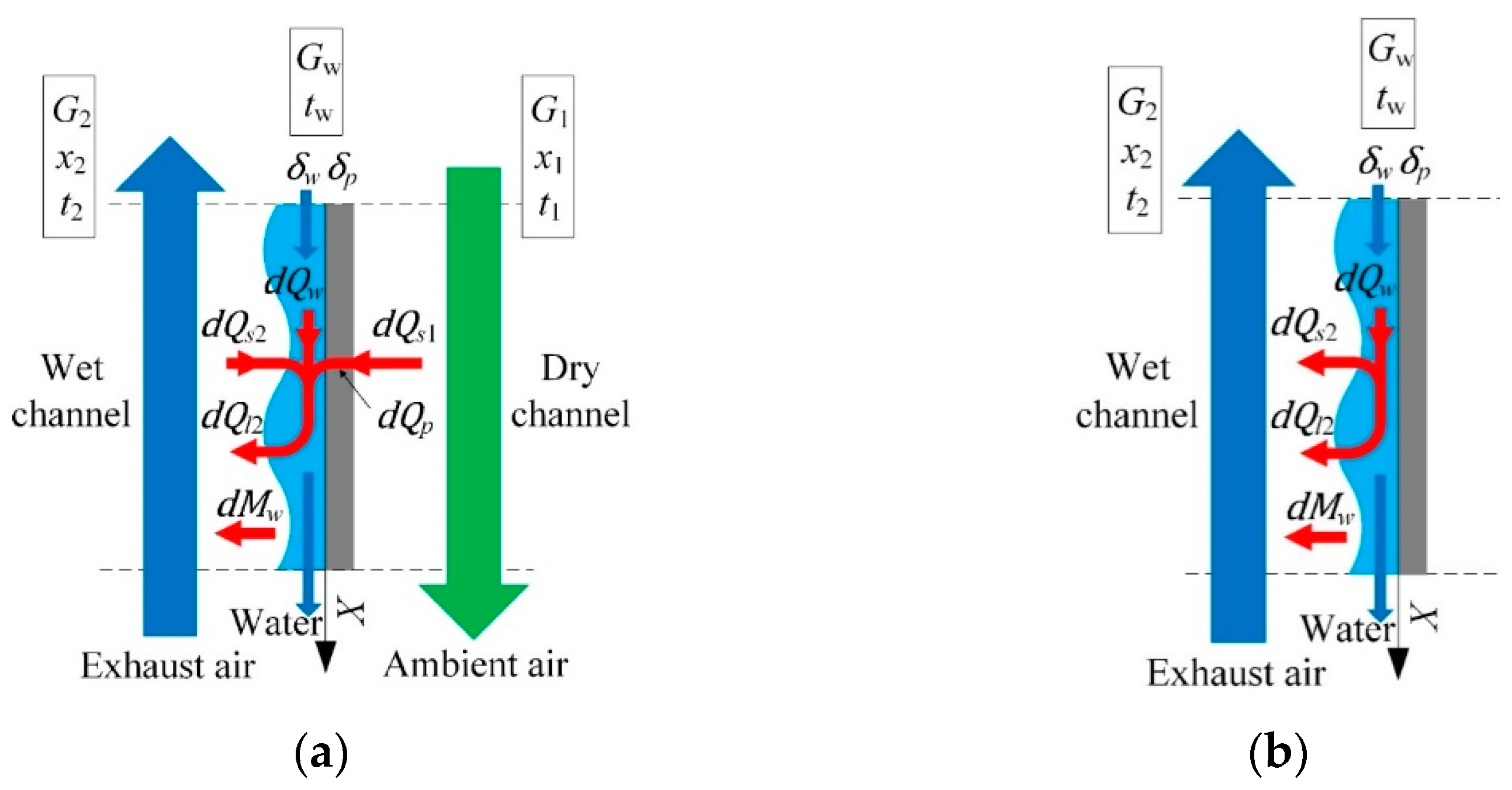
2. Heat and Mass Transfer Analysis of MCTs

The schematic of the MCT is shown in Figure 1; it is composed of parallel dry (primary) and wet (working) channels. The sensible heat of the primary (ambient) air is transferred to the wet channels, with the humidity ratio remaining constant (process 1i-1o) in the dry channels. Then, the primary air is transferred to the wet channels (becoming the working air: 1o = 2i). The working air absorbs sensible and latent heat from water (process 2i-2o), and is finally discharged into the atmosphere. The water is cooled from the state point 3i to the state point 3o, and then returns to its circuit to absorb heat from the heat source.
In this paper, a one-dimensional εNTU model was used to analyze the heat and mass transfer in MCTs [26,27,28,29]. The possibility of uneven length of the dry and wet channels of MCTs was considered by the model. As shown in Figure 2, the primary air is marked as 1, the working air is marked as 2, and the water is marked as w.
The temperature difference between the primary air t1 and the plate tp1 is the driving force of the sensible heat transfer between the dry and wet channels. Hence, the heat balance equations for primary air in the dry channels are expressed as:
d Q s 1 = α ( t p 1 t 1 ) d F
G 1 c p 1 d t 1 d x = d Q s 1
d t 1 d X = α d F G 1 c p 1 ( t p 1 t 1 ) = N T U 1 ( t p 1 t 1 )
The humidity ratio gradient between the working air x2 and the saturated air layer at the air/water interface x′w is the driving force of the mass transfer between the working air and the water. Hence, working air mass balance equations are expressed as:
d M w = β ( x w x 2 ) d F
G 2 d x 2 d X = d M w
d x 2 d X = β d F G 2 ( x w x 2 ) = α d F G 2 c p 2 β c p 2 α ( x w x 2 ) = N T U 2 ( 1 L e 2 ) ( x w x 2 )
The water film mass balance equation is as follows:
d G w d X = G 2 d x 2 d X
The heat balance equation for working air includes the sensible heat transfer and the latent heat transfer. The sensible heat transfer is driven by the temperature difference between the working air t2 and the water tw, and the latent heat transfer is connected with the evaporation of water:
d t 2 d X = N T U 2 ( t w t 2 ) + ( c p w c p ) 2 ( t w t 2 ) d x 2 d X
The energy balance equation for the water in the wet channels consists of heat transfer from water to air in dry and wet channels, along with the evaporation of water:
d t w d X = W 1 W w d t 1 d x W 2 W w d t 2 d x W 2 W w [ ( r c p w 2 c p 2 ) ( t w t 2 ) ] d x 2 d X
where:
W 1 W w = G 1 c p 1 G w c w ;   W 2 W w = G 2 c p 2 G w c w
If the wet channels are longer than the dry channels, the energy balance equations for the water are expressed as:
d t w d X = W 2 W w d t 2 d x W 2 W w [ ( r c p w 2 c p 2 ) ( t w t 2 ) ] d x 2 d X
By comparing Equations (9) and (10), it can be predicted that if the temperature of water was much higher than that of the primary air, the water would not heat the primary air, allowing for more effective pre-cooling of the primary air. This means that the uneven length of the dry and wet channels could further improve the cooling performance of MCTs. Hence, it is very important to study the effect of ldry on the performance of MCTs. At the same time, ldry directly affects NTU1, according to Equation (3). Hence, the present study also focused on the relationship between the two parameters. It can also be stated that the main operating parameters (including inlet air temperature (t1i) and humidity ratio (x1i), inlet water temperature (twi), and heat capacity ratio between air and water (W1/Ww)) also affect the performance of the MCT significantly. Due to this fact, an experimental MCT system was constructed, and the impact of the structural parameters (ldry, NTU1) and operating parameters (t1i, x1i, twi, and W1/Ww) on the performance of the MCT and the resistance characteristics of the novel fills was studied experimentally.

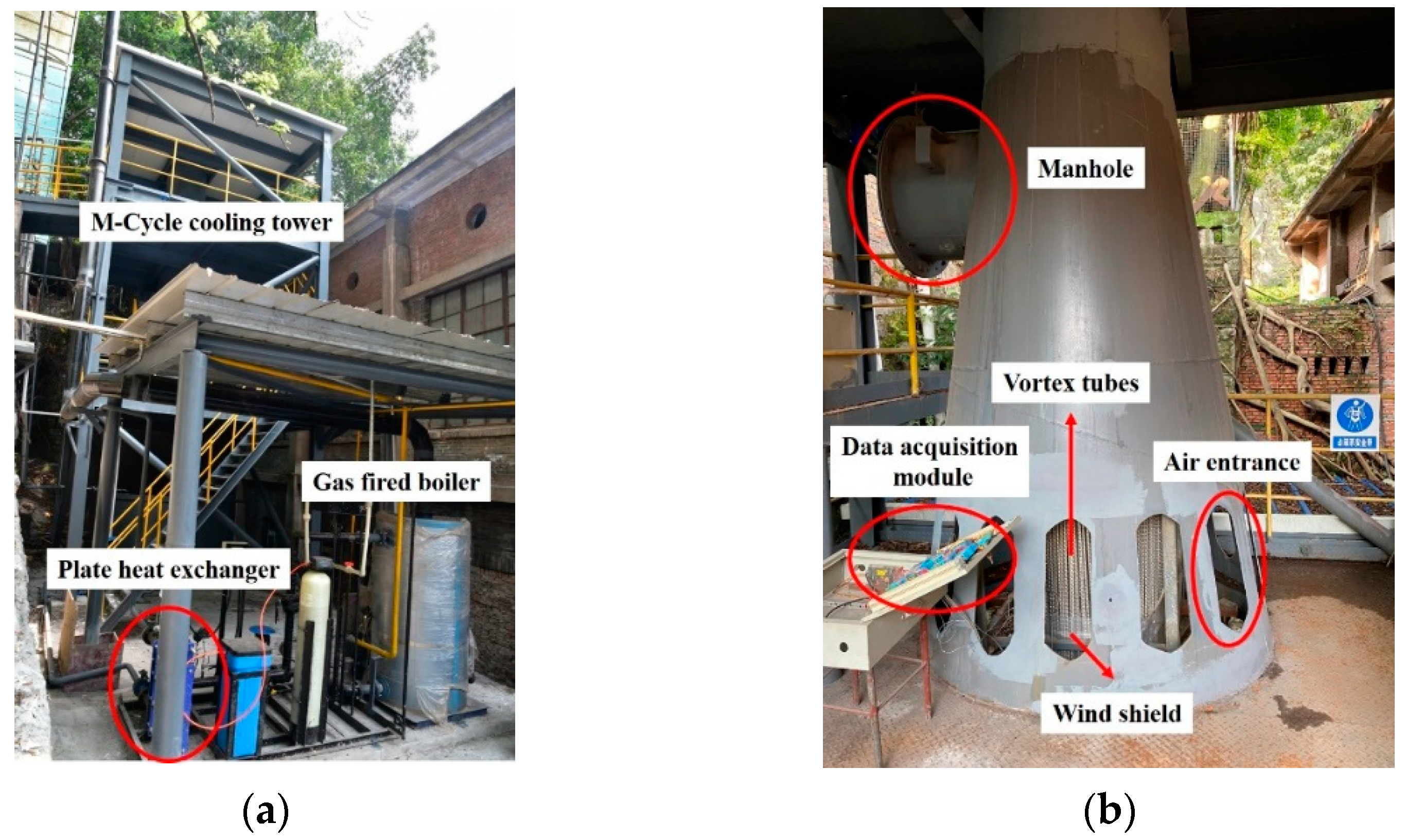
3. The Experimental System of MCTs

As shown in Figure 3, the experimental system consisted of the MCT, the air supply system, the water circulation system, and the measurement devices. The MCT consisted of the tower, the novel fill, and the cold-water reservoir, with a total height of 12 m. The novel fill consisted of vortex tubes and a wind shield, as shown in Figure 4. The outer diameter, wall thickness, and length of the vortex tubes were 13, 0.8, and 3000 mm, respectively. Unlike fills in TWCTs, the novel fill in the MCT had both dry and wet channels. In the novel fill, the primary air first flowed through gaps between vortex tubes from top to bottom and became the working air. The working air then flowed through the inner channels of the vortex tubes from bottom to top, and made contact with water flowing from top to bottom. Hence, the gaps between the vortex tubes were dry channels, and the inner channels of the vortex tubes were wet channels. In order to investigate the impact of uneven length of dry and wet channels on the cooling performance of the MCT, the length of the dry channels was changed to 1.5, 1.8, 2.1, 2.4, and 2.7 m by adjusting the height of the wind shield, and the length of wet channels remained unchanged (3.0 m), as shown in Figure 3b.
The air supply system was equipped with a frequency conversion fan installed on top of the MCT, which could control the air flow rate by changing the frequency. The water supply system was equipped with a cold-water reservoir, a frequency conversion pump, a plate heat exchanger, a gas-fired boiler, and a water distributor. The water was heated to the temperature required for the experimental conditions by the plate heat exchanger, was then evenly distributed on the novel fills by the water distributor and, finally, was collected in the cold-water reservoir to complete the water circulation. The water flow velocity was controlled by changing the frequency, and the inlet water temperature was controlled by the plate heat exchanger. The measurement devices consisted of T-type thermocouples, an ultrasonic flowmeter, a hot-wire anemometer, a Testo 645 humidity meter, and differential pressure meters, whose details are listed in Table 1. T-type thermocouples were pre-calibrated and verified before the tests, so as to accurately measure the water temperature along the wet channels. The Testo 645 humidity meter measured the air temperature and relative humidity along the dry channels and at the outlet of the wet channels. Parameters such as the water flow velocity, the inlet air velocity, and pressure drops were also measured. The details of the experimental conditions are listed in Table 2, allowing for the examination of the impact of the structural and operational parameters on the performance of the MCT and the resistance characteristics of the novel fill. The spray water rate was here defined as the ratio of the mass flow of water to the total cross-sectional area of the fills, while the air velocity in the wet channels was defined as the ratio of the mass flow of air to the total cross-sectional area of the wet channels.

4. Results and Discussion

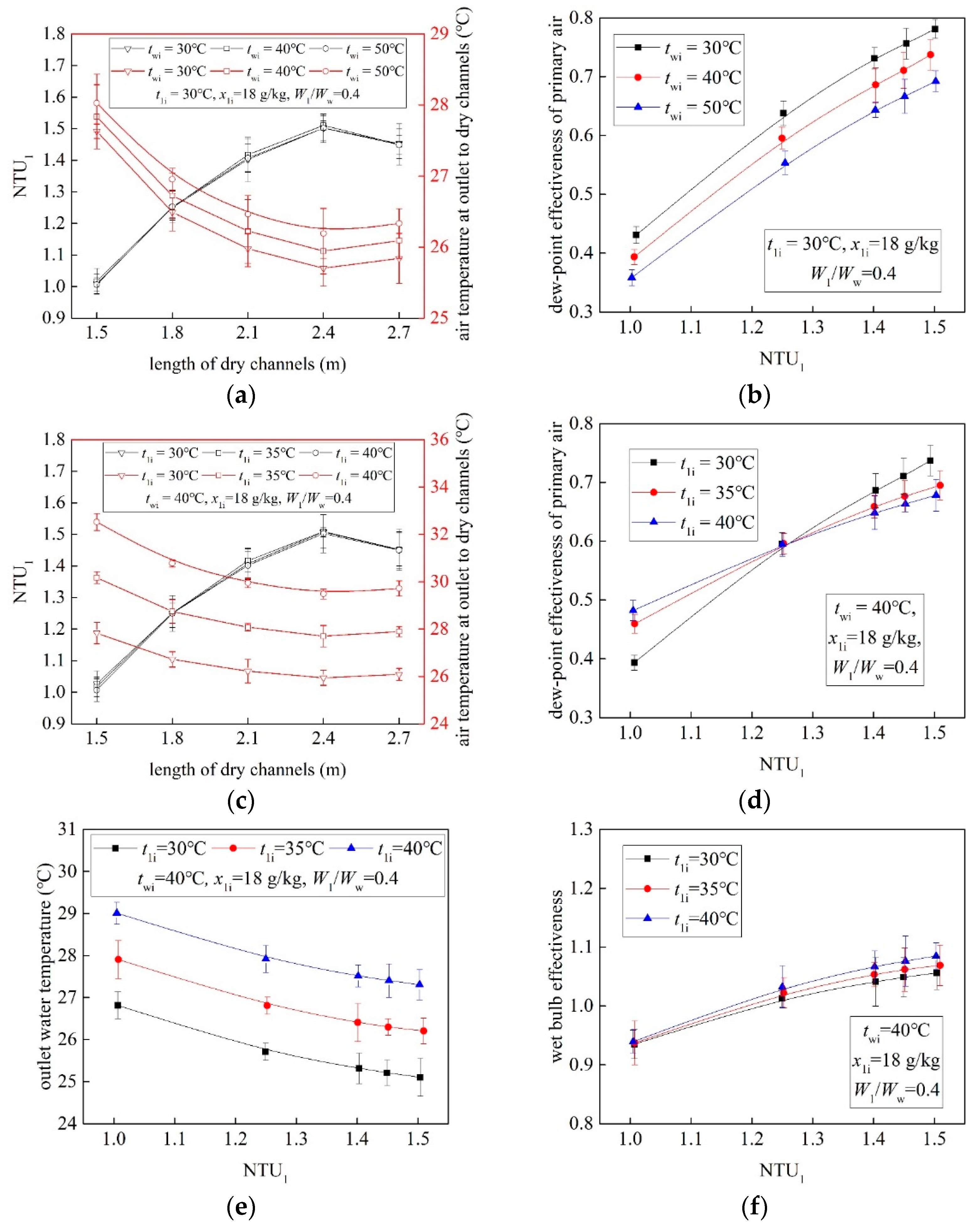
4.1. Impact of Structural Parameters on the Performance of the MCT

The impact of structural parameters on the performance of the MCT is investigated in the following section. Results showed that the length of the dry channels (ldry) affected the number of heat transfer units of primary air (NTU1) by changing the pre-cooling process in dry channels.
Figure 5a,b show the primary air and water temperature profiles along the wet channels. It can be seen that the MCT achieved the effective pre-cooling of the primary air in the dry channels (even if the inlet water temperature was much higher than the inlet air temperature, as shown in Figure 5b), and finally reduced the water temperature below the wet-bulb temperature of the primary air. The theoretical limit of TWCTs is the wet-bulb temperature of the inlet air. Due to this fact, reducing the inlet air’s wet-bulb temperature in the wet channels (t1WBo = t2WBi) can lower the theoretical limit of the MCT. Pre-cooling of the primary air without changing its humidity ratio allows for the reduction in its wet-bulb temperature; hence, the MCT can finally reduce the water temperature below the wet-bulb temperature of the primary air (t1WBi). As shown in Figure 5a, the t1WBi was 28.3 °C, and the wet-bulb temperature after pre-cooling in dry channels (t1WBo = t2WBi) was 25.4 °C, which was about 3 °C lower than t1WBi. The final outlet water temperature was 27.1 °C, which was ~1.2 °C lower than t1WBi. It can be stated that MCTs can overcome the theoretical limit of TWCTs, and have significant potential for application.
It can be also observed that the key to achieving higher effectiveness of the M-Cycle is to enhance the pre-cooling of the primary air in the dry channels. According to Equation (3), one of the most effective methods to enhance the pre-cooling is to increase the number of heat transfer units of the primary air (NTU1). How to calculate NTU1 was the first problem to be solved. As shown in Figure 5b, water heated both the primary and working air at the upper part of the wet channels. Thus, the temperature of the primary air first increased until it was equal to the water temperature; after this point, the water evaporated effectively due to contact with the low-temperature and unsaturated working air. Hence, the temperature of the primary air continuously decreased along the remaining dry channels. Due to the complex heat and mass transfer process, the logarithmic mean temperature difference (LMTD) method could not be used to directly calculate NTU1. Hence, a calculation method for NTU1 was proposed in this paper.
The equation for the heat transfer of primary air:
Q = G 1 c p 1 ( t 1 i t 1 o )
The equation for the maximum heat transfer of primary air:
Q m a x = G 1 c p 1 ( t 1 i t 1 D P i )
The equation for the dew-point effectiveness of primary air:
ε D P 1 = Q Q m a x = t 1 i t 1 o t 1 i t 1 D P i
The equation for the wet-bulb effectiveness of the MCT:
ε W P = t w i t w o t w i t 1 W P i
The equation for the heat transfer of the primary air can also be expressed as:
Q = α F Δ t m
Due to the fact that Δtm could not be calculated by using the temperature difference between the water and the primary air at the inlets and outlets of the dry channels—which was based on the LMTD method—the heat transfer process of the MCT was regarded as two separate parts for the purposes of this paper: first, evaporation transferred heat from the water to the working air, and then the water cooled the primary air. Hence, the auxiliary outlet water temperature (t′wo) was calculated by using the parameters of the working air and water, and then Δtm was calculated by the auxiliary line, as shown in Figure 5a,b.
Equations for calculating NTU1:
G w c p w ( t w i t w o ) = G 2 c p 2 ( t 2 o t 2 i )
{ Δ t m = Δ t 1 i Δ t 1 o ln Δ t 1 i Δ t 1 o Δ t 1 i = t 1 i t w o Δ t 1 o = t 1 o t w o
G 1 c p 1 ( t 1 i t 1 o ) = α F Δ t m
N T U 1 = α F G 1 c p 1 = t 1 i t 1 o Δ t m = ε D P 1 ( t 1 i t 1 D P i ) Δ t m
As shown in Figure 6a,c, NTU1 increased with of the decrease in the air temperature at the outlets of the dry channels (t1o) and decreased with the increase in t1o, meaning that the NTU1 obtained via the calculation method proposed in this paper can well represent the pre-cooling process in dry channels. Trends in Figure 6a,c also show that the length of the dry channels (ldry) affected NTU1 more significantly than the temperature of the inlet water and the inlet air. NTU1 increased from ~1.0 to 1.5 with the increase in ldry from 1.5 to 2.4 m, but decreased from ~1.5 to 1.45 with the increase in ldry from 2.4 to 2.7 m. Compared with TWCTs, the fills of the MCT had a smaller heat transfer surface where the air made direct contact with the water, because there were dry channels for pre-cooling of the primary air. The outlet water temperature of the MCT seemed to be higher than that of TWCTs; however, the results showed that the MCT obtained a lower outlet water temperature. This was caused by the fact that the MCT provided working air with a lower wet-bulb temperature for the wet channels, via the effective pre-cooling of the primary air in the dry channels. Therefore, NTU1 initially increased with the increase in the heat transfer surface (length) of the dry channels. When the dry channels were too long, the primary air was heated at the inlets to the dry channels, which was detrimental to the pre-cooling of the primary air (as shown in Figure 5b). Due to this fact, excessively long dry channels resulted in a decrease in NTU1. This indicates that finding the position where the water temperature was equal to the inlet air temperature was necessary in order to determine the optimal value of ldry for MCTs.
As shown in Figure 6b,d, the dew-point effectiveness of the primary air (εDP1) decreased with the increase in the temperature of both the inlet water (twi) and the inlet air (t1i) in the area of high NTU1, but trends of εDP1 changing with twi and t1i were different in the area of low NTU1. It can be seen that εDP1 decreased with the increase in twi, but increased with that of t1i in the area of low NTU1. This was also caused by heating of the primary air at the inlets to the dry channels. When twi was higher than t1i, increasing twi enhanced the heating of the primary air, but increasing t1i weakened this process. With the increase in NTU1, the MCT overcame the heating effect and achieved effective pre-cooling of the primary air. This indicates that a change in NTU1 of 0.5 resulted in ~30% higher εDP1. Trends in Figure 6e,f also indicate that the outlet water temperature decreased and the wet-bulb effectiveness increased with increasing NTU1. A change of 0.5 in NTU1 resulted in the wet-bulb effectiveness (εWB) being ~10% higher. It can be stated that MCTs should maximize NTU1 within the optimal value of pressure drops.

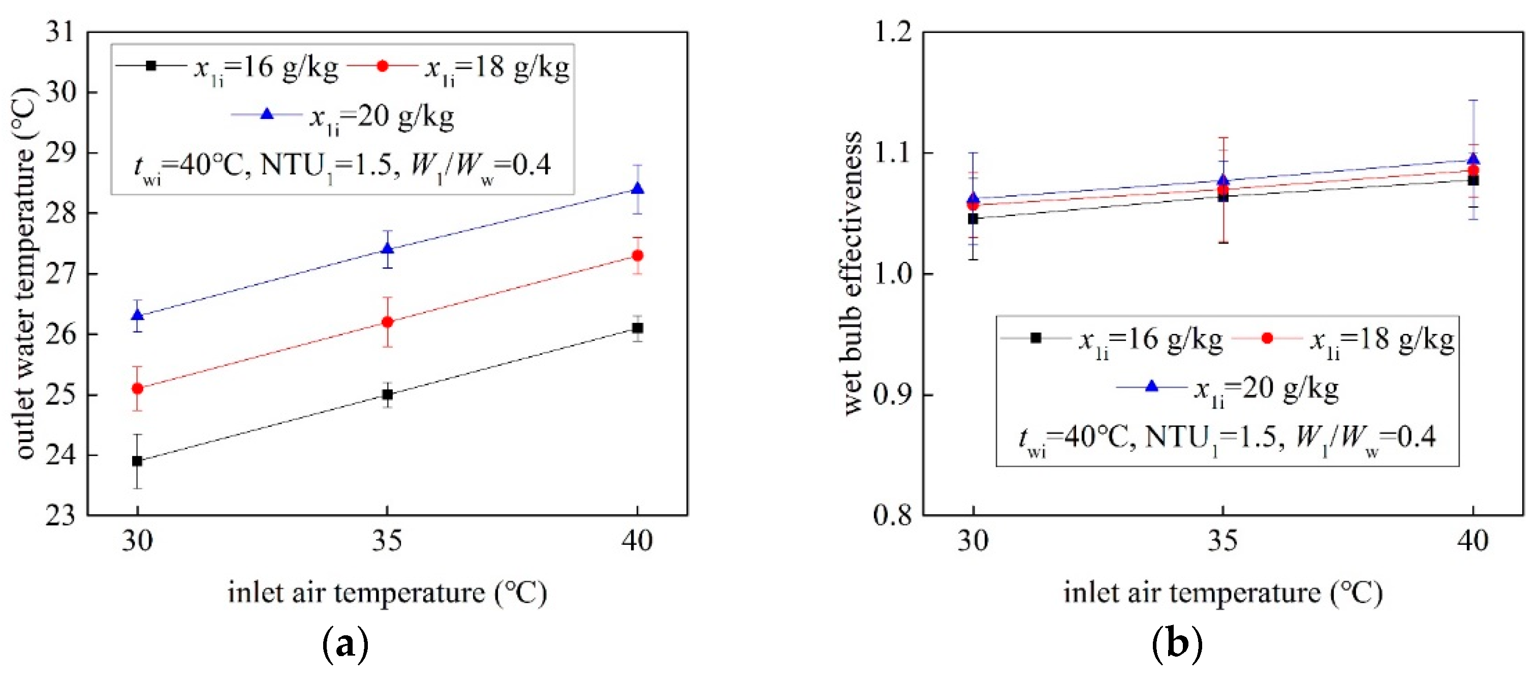
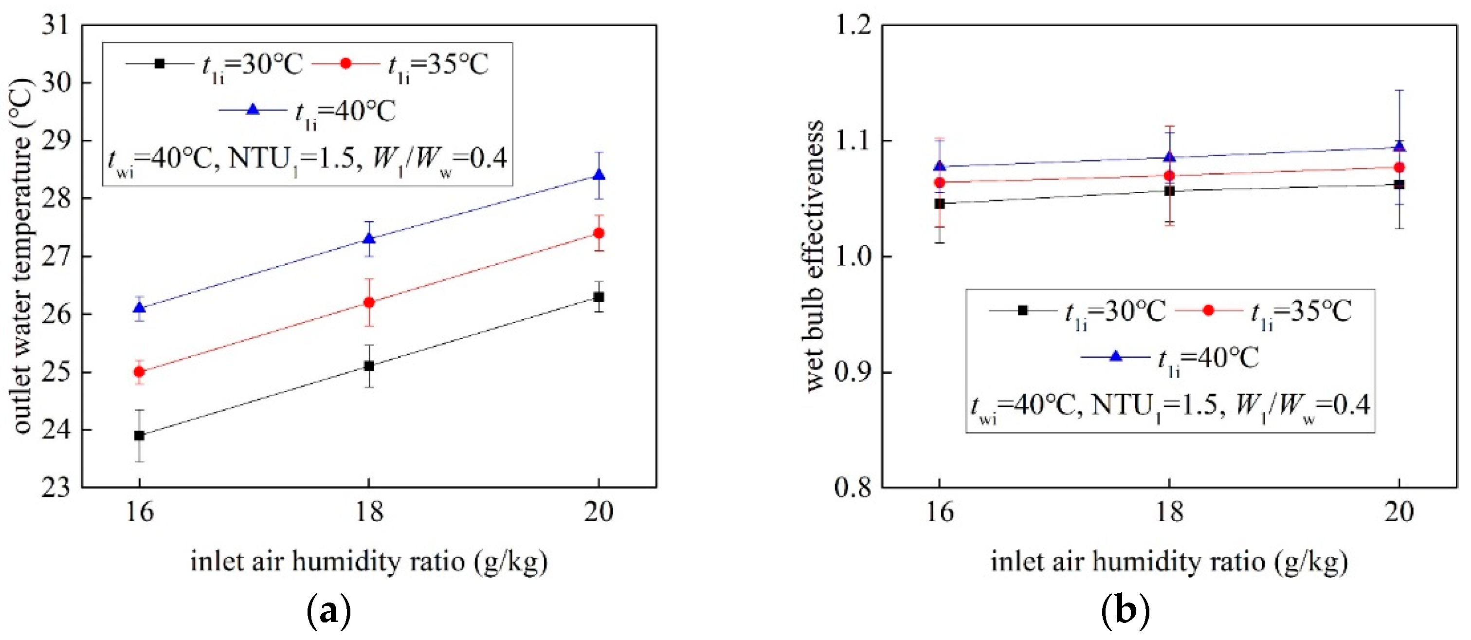
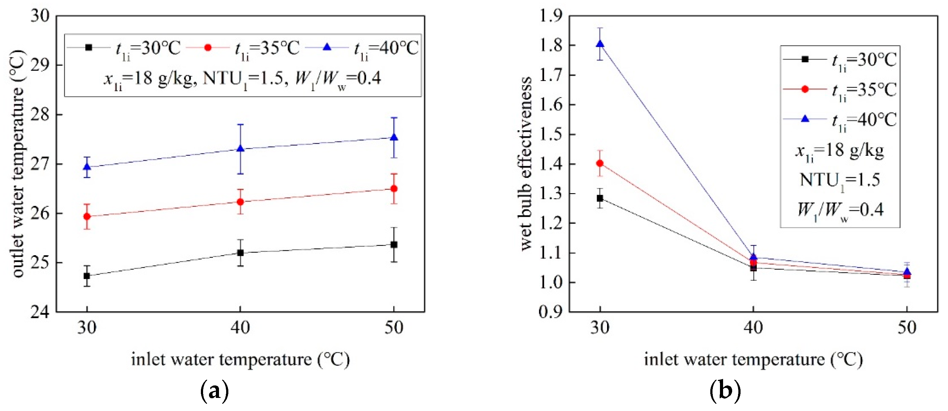
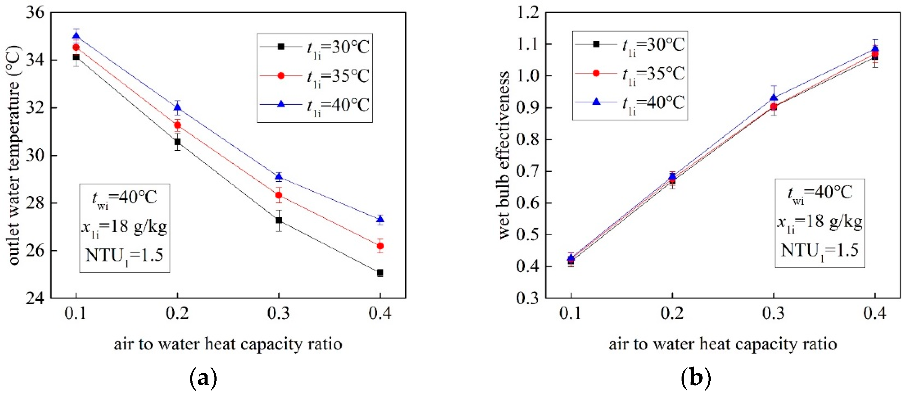
4.2. Impact of Operating Parameters on the Performance of the MCT

The impact of operating parameters on the performance of the MCT is investigated in the following section. Results showed that the εWB of MCTs can reach the maximum value of 180%, which is not achievable by TWCTs. Even under conditions of t1i ≥ 35 °C and x1i ≥ 16 g/kg, the εWB of MCTs can still be higher than 100%, indicating that MCTs are still applicable under very high inlet air temperatures and humidity ratios.
Figure 7a,b show the impact of the inlet air temperature (t1i) on the performance of the MCT. It can be seen that higher t1i led to a higher outlet water temperature (two), but the change in t1i scarcely affected two. Changing t1i from 30 to 40 °C resulted in two changing by ~2.2 °C. Because increasing the temperature of the inlet air without changing its humidity ratio led to an increase in water evaporation in the wet channels, the value of two was reduced to a lower level in order to achieve the effective pre-cooling of the primary air. The wet-bulb temperature of the air at the outlets of the dry channels, which was the theoretical limit of a TMCT, rarely changed under various conditions. Due to this fact, two showed no significant change. This was also why εWB increased rather than decreasing with the increase in the value of t1i. Effective pre-cooling of the primary air made the wet-bulb temperature of the air at the outlets of the dry channels much lower than that at the inlets to the dry channels. Hence, εWB increased from ~104% to 109% with t1i changing from 30 to 40 °C, as shown in Figure 6b. Therefore, it can be stated that MCTs have the potential to be used in hot climates, where TWCTs often show lower efficiency.
Figure 8a,b show the impact of the inlet air humidity ratio (x1i) on the performance of the MCT. Changing x1i from 16 to 20 g/kg resulted in two increasing by ~2.4 °C. The trends indicate that the change in two with x1i changing by 4 g/kg was twofold greater than that with t1i changing by 5 °C, meaning that x1i affected two more significantly than t1i, even under a very high humidity ratio. Unlike the impact of increasing t1i on the pre-cooling process in the dry channels, increasing the humidity ratio of the inlet air without changing its dry-bulb temperature resulted in an increase in the dew-point temperature and a decrease in the ability to absorb water vapor. Hence, higher x1i led to higher two by increasing the theoretical limit of the MCT. However, changing x1i scarcely affected εWB. Figure 6d shows that εWB changed by less than 2% when x1i increased from 16 to 20 g/kg. This was due to the fact that both the inlet wet-bulb temperature (t1WBi) and two increased in proportion with the increase in x1i. Therefore, it can be stated that MCTs could still retain high εWB even in very wet climates.
Figure 9a,b show the impact of the inlet water temperature (twi) on the performance of the MCT. It can be seen that increasing twi led to lower efficiency of the MCT. Similar to increasing t1i, two increased with the increase in twi, but showed no significant change. Changing twi from 30 to 50 °C resulted in two increasing by ~0.6 °C. This was also caused by effective pre-cooling, which reduced the impact of increasing twi. Unlike increasing t1i, εWB decreased with the increase in twi. The maximum εWB was ~180% when twi was 30 °C, and sharply reduced to ~105% when twi was 40 °C. However, twi scarcely affected εWB when twi was higher than 40 °C. Due to the fact that the temperature difference between twi and t1WBo was too small under conditions of low temperature and high humidity ratio, the small drop in the water temperature (by ~5.2 °C, Figure 6e) still led to a large εWB. With the increase in twi, the temperature difference between twi and t1WBo—and that between twi and two—increased in proportion, due to the fact that twi had no significant effect on two. Therefore, the impact of increasing twi on εWB was not significant.
Figure 10a,b show the impact of the heat capacity ratio between the air and the water (W1/Ww) on the performance of the MCT. It can be seen that W1/Ww significantly affected the efficiency of the MCT. With W1/Ww changing from 0.1 to 0.4, two decreased by approximately 7.7 and 9.1 °C when t1i was equal to 40 and 30 °C, respectively, and εWB increased from ~41% to 109%. This was also connected with the pre-cooling process in the dry channels. When the heat capacity of the air was much lower than that of the water (W1/Ww = 0.1), the evaporation of water in the wet channels dramatically decreased, and the primary air was heated for a longer distance in the dry channels. With the increase in W1/Ww (W1/Ww =0.4), the evaporation of water increased, and the MCT overcame the heating effect and achieved effective pre-cooling of the primary air, which resulted in high efficiency of the MCT. It can be stated that in order to ensure that MCTs have high wet-bulb efficiency (εWB ≥ 0.9), W1/Ww should be maintained at a high value (W1/Ww ≥ 0.3).

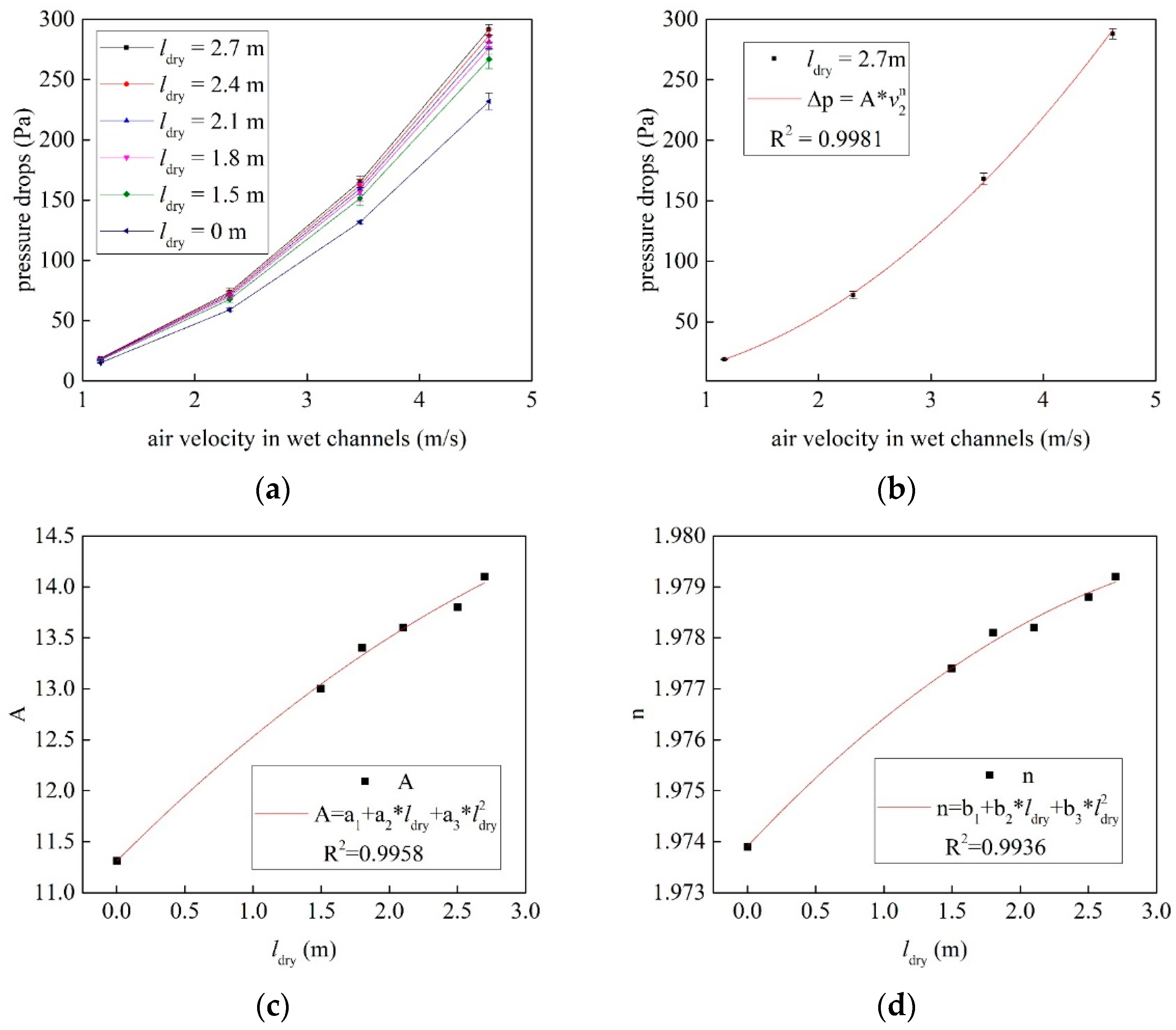
4.3. Resistance Characteristics of the Novel Fill

With the aim of applying the M-cycle in TWCTs, the fill of MCTs must have adjacent dry and wet channels. Through the special channel arrangement, the air flows through the dry channels and then enters the wet channels, meaning that the pressure drops can be very high. Hence, it is necessary to study the resistance characteristics of the novel fill. Figure 11 shows the variation in pressure drops (Δp) with different air velocities in the wet channels (v2).
As shown in Figure 11a, when v2 was equal to 4.62 m/s, Δp increased by ~16.74% with the increase in ldry from 0 to 1.5 m, but increased by ~7.65% with the increase in ldry from 1.5 to 2.7 m. Because the MCT had dry and wet channels, the air changed direction at least twice in the novel fills. Due to this fact, Δp increased dramatically compared with the traditional fills. Therefore, the novel fill should be designed to minimize the angle of the change in the air’s direction.
As shown in Figure 7b, the fitting equation for Δp vs. v2 is expressed as:
Δ p = A v 2 n
where:
A = 0.122 l d r y 2 + 1.341 l d r y + 11.309 n = 3.446 × 10 4 l d r y 2 + 2.8 × 10 3 l d r y + 1.974
This indicates that v2 affected Δp more significantly than changing ldry according to the fitting equation; it also provides a guideline for the optimization of resistance characteristics in MCTs.

5. Conclusions

An experimental system for MCTs was constructed, and detailed theoretical analysis and experimental research were carried out. A calculation method of NTU1 was proposed, and the impact of structural (ldry and NTU1) and operational parameters (tw, t1, x1i, and W1/Ww) on the performance of MCTs was investigated. Resistance characteristics of the novel fill were also studied. The main conclusions can be summarized as follows:
  • The water was cooled below the inlet air’s wet-bulb temperature the MCT, which is not achievable by TWCTs;
  • NTU1 increased from ~1.0 to 1.5 with an increase in ldry from 1.5 to 2.4 m, but decreased from ~1.5 to 1.45 with an increase in ldry from 2.4 to 2.7 m. Therefore, it is important to ensure the optimal value of ldry for MCTs;
  • The wet-bulb effectiveness increased by ~10% with an increase in NTU1 of ~0.5, indicating that MCTs should maximize NTU1 within the optimal value of pressure drops;
  • The inlet air’s humidity ratio affected wet-bulb effectiveness more significantly than its temperature; however, the MCT still obtained wet-bulb effectiveness of up to ~180%, even under conditions of very high inlet air temperature and humidity ratio (t1i ≥ 35 °C, x1i ≥ 16 g/kg);
  • In order to ensure that MCTs have high wet-bulb efficiency (εWB ≥ 0.9), W1/Ww should be maintained at a high value (W1/Ww ≥ 0.3);
  • The results of this study have significance for the guidance of the industrial application and performance improvement of MCTs.

Author Contributions

Conceptualization, X.L. and X.F.; investigation, X.F., X.L. and Q.W.; methodology, X.L. and X.F.; writing—original draft preparation, X.F.; writing—review and editing, Z.D. and R.Z.; validation, J.W. and Z.L. All authors have read and agreed to the published version of the manuscript.

Funding

This research received no external funding.

Institutional Review Board Statement

Not applicable.

Informed Consent Statement

Not applicable.

Data Availability Statement

The data that support the findings of this study are available from the corresponding author upon reasonable request.

Acknowledgments

The authors are thankful to the stuff from SPIC Yuanda Environmental Protection’s Science and Technology Branch for valuable support during the long-term field tests.

Conflicts of Interest

The authors declare no conflict of interest.

Nomenclature

cpSpecific heat capacity of moist air, (J/(kg K))
cpwSpecific heat capacity of water vapor, (J/(kg K))
cwSpecific heat capacity of water, (J/(kg K))
FSurface area, (m2)
GMass flow rate, (kg/s)
lLength, (m)
MWater vapor mass transfer rate, (kg/s)
rSpecific heat of water evaporation, (kJ/kg)
QRate of heat transfer, (W)
tTemperature, (°C)
ΔtmLogarithmic mean temperature difference, (°C)
WHeat capacity rate of the fluid, (W/K)
xHumidity ratio, (kg/kg)
XCoordinate along water flow direction, (m)
vVelocity, (m/s)
ΔpPressure drops, (Pa)
Special characters
αConvective heat transfer coefficient, (W/(m2 K))
βMass transfer coefficient, (kg/(m2 s))
εEffectiveness, (–)
εDP1Dew-point effectiveness of primary air, (–)
εWBWet-bulb effectiveness of MCT, (–)
Non dimensional coordinates
LeLewis factor, Le =α/(βcp), (–)
NTUNumber of transfer units, NTU =αF/(Gcp), (–)
subscripts
1Primary airflow in dry channel
2Working airflow in wet channel
iInlet
oOutlet
pChannel plate
wWater
WBWet-bulb temperature
DPDew-point temperature
dryDry channels
wetWet channels
Conditions at air/water interface

References

  1. Bolatturk, A.; Coskun, A.; Geredelioglu, C. Thermodynamic and exergoeconomic analysis of Çayırhan thermal power plant. Energy Convers. Manag. 2015, 101, 371–378. [Google Scholar] [CrossRef]
  2. Pan, S.-Y.; Snyder, S.W.; Packman, A.I.; Lin, Y.J.; Chiang, P.-C. Cooling water use in thermoelectric power generation and its associated challenges for addressing water-energy nexus. Water-Energy Nexus 2018, 1, 26–41. [Google Scholar] [CrossRef]
  3. Ayoub, A.; Gjorgiev, B.; Sansavini, G. Cooling towers performance in a changing climate: Techno-economic modeling and design optimization. Energy 2018, 160, 1133–1143. [Google Scholar] [CrossRef]
  4. Pandelidis, D.; Cichoń, A.; Pacak, A.; Anisimov, S.; Drąg, P. Application of the cross-flow Maisotsenko cycle heat and mass exchanger to the moderate climate in different confgurations in air-conditioning systems. Int. J. Heat Mass Transf. 2018, 122, 806–817. [Google Scholar] [CrossRef]
  5. Schulze, C.; Raabe, B.; Herrmann, C.; Thiede, S. Environmental Impacts of Cooling Tower Operations—The Influence of Regional Conditions on Energy and Water Demands. Procedia CIRP 2018, 69, 277–282. [Google Scholar] [CrossRef]
  6. Chen, X.; Sun, F.; Chen, Y.; Gao, M. Novel method for improving the cooling performance of natural draft wet cooling towers. Appl. Therm. Eng. 2019, 147, 562–570. [Google Scholar] [CrossRef]
  7. Chen, X.; Sun, F.; Chen, Y.; Gao, M. New retrofit method to improve the thermal performance of natural draft wet cooling towers based on the reconstruction of the aerodynamic field. Int. J. Heat Mass Transf. 2019, 132, 671–680. [Google Scholar] [CrossRef]
  8. Zhang, Z.; Gao, M.; Wang, M.; Guan, H.; Dang, Z.; He, S.; Sun, F. Field test study on thermal and ventilation performance for natural draft wet cooling tower after structural improvement. Appl. Therm. Eng. 2019, 155, 305–312. [Google Scholar] [CrossRef]
  9. Kang, D.; Strand, R.K. Significance of parameters affecting the performance of a passive down-draft evaporative cooling (PDEC) tower with a spray system. Appl. Energy 2016, 178, 269–280. [Google Scholar] [CrossRef] [Green Version]
  10. Cui, H.; Li, N.; Peng, J.; Yin, R.; Li, J.; Wu, Z. Investigation on the thermal performance of a novel spray tower with upward spraying and downward gas flow. Appl. Energy 2018, 231, 12–21. [Google Scholar] [CrossRef]
  11. Lu, Y.; Klimenko, A.; Russell, H.; Dai, Y.; Warner, J.; Hooman, K. A conceptual study on air jet-induced swirling plume for performance improvement of natural draft cooling towers. Appl. Energy 2018, 217, 496–508. [Google Scholar] [CrossRef]
  12. Maisotsenko, V.; Gillan, L.E.; Heaton, T.L.; Gillan, A.D. Method of Evaporative Cooling of a Fluid and Apparatus Therefor. U.S. Patent 6,854,278, 15 February 2005. [Google Scholar]
  13. Mahmood, M.H.; Sultan, M.; Miyazaki, T.; Koyama, S.; Maisotsenko, V.S. Overview of the Maisotsenko cycle—A way towards dew point evaporative cooling. Renew. Sustain. Energy Rev. 2016, 66, 537–555. [Google Scholar] [CrossRef]
  14. Anisimov, S.; Pandelidis, D. New trends in cooling towers and dry coolers. Refrig. Air Cond. 2012, 17, 28–31. (In Polish) [Google Scholar]
  15. Lin, A.J.; Thu, K.; Bui, T.D.; Wang, R.Z.; Chua, K.J. Study on dew point evaporative cooling system with counter-flow confguration. Energy Convers. Manag. 2016, 1231, 200–208. [Google Scholar]
  16. Dizaji, H.S.; Hu, E.J.; Chen, L.; Pourhedayat, S. Development and validation of an analytical model for perforated (multi-stage) regenerative M-cycle air cooler. Appl. Energy 2018, 228, 2176–2194. [Google Scholar] [CrossRef]
  17. Heidari, A.; Roshandel, R.; Vakiloroaya, V. An innovative solar assisted desiccant-based evaporative cooling system for co-production of water and cooling in hot and humid climates. Energy Convers. Manag. 2019, 185, 396–409. [Google Scholar] [CrossRef]
  18. Pakari, A.; Ghani, S. Regression models for performance prediction of counter flow dew point evaporative cooling systems. Energy Convers. Manag. 2019, 185, 562–573. [Google Scholar] [CrossRef]
  19. Zhang, L.; Zha, X.; Song, X.; Zhang, X. Optimization analysis of a hybrid fresh air handling system based on evaporative cooling and condensation dehumidification. Energy Convers. Manag. 2019, 180, 83–93. [Google Scholar] [CrossRef]
  20. Burger, R. Profits and Cold Water. Eng. Syst. 2000, 17, 86–94. [Google Scholar]
  21. Gillan, L.; Glanville, P.; Maisotsenko, K.A. Cycle Enhanced Cooling Towers. In Proceedings of the 2011 Cooling Technology Insititute Annual Conference, San Antonio, TX, USA, 6–10 February 2011; pp. 1–7. [Google Scholar]
  22. Morosuk, T.; Tsatsaronis, G. Advanced cooling tower concept based on the Maisotsenko-cycle—An exergetic evaluation. Int. J. Energy A Clean Environ. 2011, 12, 159–173. [Google Scholar] [CrossRef]
  23. Morosuk, T.; Tsatsaronis, G.; Maisotsenko, V.; Kozlov, A. Exergetic Analysis of a Maisotsenko-Process-Enhanced Cooling Tower. Am. Soc. Mech. Eng. 2012, 6, 189–194. [Google Scholar]
  24. Sverdlin, B.; Tikhonov, A.; Gelfand, R. Theoretical possibility of the Maisotsenko cycle application to decrease cold water temperature in cooling towers. Int. J. Energy A Clean Environ. 2011, 12, 175–185. [Google Scholar] [CrossRef] [Green Version]
  25. Anisimov, S.; Kozlov, A.; Glanville, P.; Khinkis, M.; Maisotsenko, V.; Shi, J. Advanced Cooling Tower Concept for Commercial and Industrial Applications. In Proceedings of the ASME 2014 Power Conference, Baltimore, MA, USA, 28–31 July 2014. [Google Scholar]
  26. Pandelidis, D. Numerical study and performance evaluation of the Maisotsenko cycle cooling tower. Energy Convers. Manag. 2020, 210, 112735. [Google Scholar] [CrossRef]
  27. Pandelidis, D.; Drąg, M.; Drąg, P.; Worek, W.; Cetin, S. Comparative analysis between traditional and M-Cycle based cooling tower. Int. J. Heat Mass Transf. 2020, 159, 120124. [Google Scholar] [CrossRef]
  28. Anisimov, S.; Pandelidis, D. Theoretical study of the basic cycles for indirect evaporative air cooling. Int. J. Heat Mass Transf. 2015, 84, 974–989. [Google Scholar] [CrossRef]
  29. Stoitchkov, N.J.; Dimitrov, G.I. Effectiveness of cross-flow plate heat exchanger for indirect evaporative cooling. Int. J. Refrig. 1998, 21, 463–471. [Google Scholar] [CrossRef]
Figure 1. Schematic of the M-Cycle cooling tower.
Energies 14 08249 g001
Figure 2. Schematic of the mathematical processes of MCTs: (a) the wet channel being equal to the dry channel; (b) the wet channel being longer than the dry channel.
Energies 14 08249 g002
Figure 3. (a) The scheme of the experimental system and (b) the arrangement of the temperature measurement points along the tubes: 1—frequency conversion fan; 2—hot-wire anemometer; 3—water distributor; 4—ultrasonic velocity meter; 5—cooling tower column; 6—vortex tubes; 7—wind shield; 8—cold-water basin; 9—cold-water reservoir; 10—frequency conversion pump; 11—valve; 12—plate heat exchanger; 13—gas-fired boiler; 14— T-type thermocouple; 15—Testo 645 humidity meter.
Energies 14 08249 g003
Figure 4. (a) The overall layout of the experimental system, and (b) the arrangement of the novel fill with uneven length of dry and wet channels.
Energies 14 08249 g004
Figure 5. Temperature profiles under different inlet water temperatures: (a) twi = 30 °C; (b) twi = 50 °C.
Energies 14 08249 g005
Figure 6. Impact of structural parameters on the performance of the MCT: (a) ldry vs. NTU1 and two; (b) NTU1 vs. εDP1; (c) ldry vs. NTU1 and t1o; (d) NTU1 vs. εDP1; (e) NTU1 vs. two; (f) NTU1 vs. εWB.
Energies 14 08249 g006
Figure 7. Impact of the inlet air temperature on the performance of the MCT: (a) t1i vs. two; (b) t1i vs. εWB.
Energies 14 08249 g007
Figure 8. Impact of the inlet air humidity ratio on the performance of the MCT: (a) x1i vs. two; (b) x1i vs. εWB.
Energies 14 08249 g008
Figure 9. Impact of the inlet water temperature on the performance of the MCT: (a) twi vs. two; (b) twi vs. εWB.
Energies 14 08249 g009
Figure 10. Impact of the heat capacity ratio between air and water on the performance of the MCT: (a) w1/ww vs. two; (b) w1/ww vs. εWB.
Energies 14 08249 g010
Figure 11. Impact of air velocity in wet channels on the pressure drops of the novel fills: (a) Δp vs. v2 with different ldry; (b) fitting equation for Δp vs. v2; (c) fitting equation for A vs. ldry; (d) fitting equation for n vs. ldry.
Energies 14 08249 g011
Table 1. Specification of measurement devices.
ParametersInstrumentsAccuracyRange
Temperature of waterT-type thermocouple±0.1 °C−50~200 °C
Water flow velocityUltrasonic flowmeter±0.5%0.005~32 m/s
Inlet air velocityHot-wire anemometer±3%0~50 m/s
Temperature and relative humidity of airTesto 645 humidity meter±0.1 °C,
±0.1% RH
−50~150 °C,
0~100% RH
Pressure dropsDifferential pressure meters±0.5%0~500 Pa
Table 2. Details of experimental conditions.
Experimental ParametersExperimental Details
Length of dry channels ldry1.5, 1.8, 2.1, 2.4, and 2.7 m
Inlet water temperature twi30, 40, and 50 °C
Inlet air temperature t1i30, 35, and 40 °C
Inlet air humidity ratio x1i16, 18, and 20 g/kg
Water flow rate Gw (spray water rate)1.496 t/h (12 t/h·m2)
Air flow rate G1 (air velocity in wet channels va)518, 1037, 1555, and 2073 m3/h (1.16, 2.31, 3.47, and 4.62 m/s, respectively)
heat capacity ratio between air and water W1/Ww0.1, 0.2, 0.3 and 0.4
Publisher’s Note: MDPI stays neutral with regard to jurisdictional claims in published maps and institutional affiliations.

