Review

A Review of Active Aerodynamic Systems for Road Vehicles

Institute of Aeronautics and Applied Mechanics, Warsaw University of Technology, 00-665 Warsaw, Poland
Energies 2021, 14(23), 7887; https://doi.org/10.3390/en14237887
Submission received: 30 September 2021 / Revised: 24 October 2021 / Accepted: 18 November 2021 / Published: 24 November 2021
(This article belongs to the Special Issue Future of Road Vehicle Aerodynamics)

Abstract

:
Comfort, safety, high travel speeds, and low fuel consumption are expected characteristics of modern cars. Some of these are in conflict with one other. A solution to this conflict may be time-varying body geometry realized by moving aerodynamic elements and appropriate systems for controlling their motion. This paper presents a review of existing technical solutions and the results of published research on the effects of active flow control around a vehicle on its dynamic properties. Active aerodynamic systems typically adjust certain aerodynamic characteristics based on the vehicle speed, but systems using other information such as acceleration, yaw rate, steering angle, and brake pressure, as well as fully automatic systems, are also considered. This review provides information on historical and current methods, models, and their effectiveness in designing vehicle bodies and the movable aerodynamic elements mounted on them. Technical solutions in which the driver is an element of the control system, automatic systems, their models, models of movable aerodynamic elements, and coupled dynamic-aerodynamic models are presented. A number of types of moving aerodynamic element solutions used for different purposes are considered in this paper and conclusions are presented.

1. Introduction

The influence of aerodynamics on vehicle behavior has been known for years. This influence was mainly observed during various types of races when vehicle speeds were high. For many years, it was believed that its main manifestation was aerodynamic drag. Therefore, efforts were made for vehicles to have the lowest possible aerodynamic drag coefficients and a small frontal area. Attempts were made to reduce the observed instability at high speeds using vertical stabilizers. The stabilizers worked, but only for large angular deviations of the vehicles from the assumed direction of travel. The relationship between vehicle dynamics and the aerodynamic vertical force generated by the bodies was identified relatively late. Previously unexplained symptoms of directional instability occurring at high speeds in vehicles with low aerodynamic drag began to be linked to the aerodynamic lift force generated on them, which reduced the force acting on the rear wheels at high speeds, causing their sideslip angles to increase, which was a direct cause of instability.
Work commenced to develop vehicles with aerodynamic elements pressing the vehicle against the road. However, generating aerodynamic downforce came at the cost of increased aerodynamic drag. The natural solution was to use moving aerodynamic elements at lower speeds during cornering, which were turned off at high speeds on straight sections of the track. This was extremely effective, but as a result of underestimating the increase in vehicle performance during cornering, the design solutions proved to be too fragile and dangerous. As a result of several accidents on the track, this type of solution was banned. This state of affairs continued for decades.
Increasing knowledge of vehicle dynamics and the development of computers led researchers to other ways of using moving aerodynamic elements. Analyses of the relationship between ride comfort and grip on rough roads using only mechanical elements, springs, and shock absorbers, showed the impassable limits of possible solutions. The time-varying external forces offered by aerodynamics were used to circumvent them.
Analyses of the operation of moving aerodynamic elements are usually carried out in two different ways, unfortunately independently of each other. Control models of these elements are built based on vehicle dynamics models of varying complexity, but always with simplified models of the moving aerodynamic elements. There are only a few papers that include theoretical control models with full vehicle aerodynamics models. Complex car dynamics models have been built to consider the moving aerodynamic elements of a car but without control systems.
Yu and Gao [1] and Gao et al. [2] reviewed the influence of active aerodynamic tails on vehicle handling stability and the state of the art in active aerodynamic control research for vehicles, but only from the point of view of control system specialists.
The present paper puts forward a different point of view: the papers reviewed herein have been analyzed from the point of view of an aerodynamicist.
Studies related to safety and comfort are typically conducted by groups of researchers working on control problems. On the other hand, studies to determine the aerodynamic properties of moving components mounted on a car body are the domain of researchers working on aerodynamics and numerical flow simulation (CFD) methods. Due to their different areas of expertise and experience, these groups have different approaches to the problem of the application of moving aerodynamic components.
The main purpose of this paper is to show both the achievements and shortcomings of the different papers and to suggest joint efforts for obtaining more realistic solutions to very complex problems.

2. Existing Technical Solutions without Documentation in the Form of Publications

The aerodynamics of road vehicles in the early period of their development benefited from the experience of aeronautical aerodynamics gained earlier.
The record-breaking car, the Mercedes-Benz T80 (Figure 1), produced in 1939 to break the land speed record, had a number of additional aerodynamic elements. In addition to fixed airfoils, the design included a number of movable aerodynamic elements. The planned speed was 750 km/h [3].
The 1928 Opel RAK2 (Figure 2) rocket-propelled vehicle used large additional wings set at a negative angle to realize downforce on the road to stabilize its movement at high speed. The car set a new land speed record of 148 mph (238 km/h) [4]. The 1952 Mercedes-Benz 300 SL Prototipo race car (Figure 3) was equipped with a manually operated air brake mounted on the roof which could be adjusted to a vertical or horizontal position, when it needed to be actuated or not.
The Mercedes-Benz 300 race cars, equipped with huge drum brakes hidden inside the body connected to the wheels by shafts with joints, were prone to overheating, which caused great maintenance problems. Therefore, engineers mounted a large aerodynamic brake, in the form of a hydraulically raised rear body cover, during test drives (Figure 4). The solution was very effective and was patented [5]. Recently performed numerical calculations [6] revealed an increase by 0.40 in the drag coefficient and aerodynamic downforce caused by the application of the aerodynamic brake. Experimental data [7] indicated an even higher drag coefficient (0.65). The application of the aerodynamic brake increased the frontal area of the car by 24% [8] and the aerodynamic brake had a significant effect only on the vertical load on the rear axle of the car [8,9].
In 1956, Michael May, a talented Swiss enthusiast, used his aerodynamics knowledge and engineering skills to make modifications to his 550 Spyder race car [10]. His Porsche 550 roadster (Figure 5) was fitted with a movable wing over the open cockpit. Winged race cars had been tried before, but the adjustable device on May’s 550 Spyder transferred loads directly to the car’s center of gravity. With better grip, Michael May and his private car achieved fourth lap time during practice for the 1000 km race at the Nürburgring in 1956.
Porsche formally forced the organizers to acknowledge the alleged safety impact of the May device, namely, that it would obstruct the view of those coming from behind. However, the real reason was different. The modifications introduced made May’s 550 Spyder significantly faster than other 1500 cc cars. The solution was so effective that it became a threat to the Porsche factory team and was forgotten for many years.
Jim Hall built the Chaparral 2C model [11] with a large movable tailgate operated by the driver pressing an extra pedal with his left foot (Figure 6). This was possible due to the semi-automatic transmission used in this car. The integrated spoiler-wing was designed to lie flat to provide low drag on straights and to rise during braking while cornering. The aerodynamic solution was so effective that it overloaded the vehicle’s suspension and made the ride very unpleasant for the driver.
Therefore, the Chaparral 2F car used a large wing with a variable angle of attack (Figure 7), placed high above the body, from which aerodynamic forces were transferred not to the body but directly to the rear wheel bearing housings of the vehicle [12].
The Porsche 908 25 series cars were equipped with movable flaps whose movement was mechanically coupled to the movement of the rear wheel suspension.
Another example of a race car with active aerodynamics was the 1968 Porsche 908 LH, which featured two flaps at the rear of the car directly connected to the suspension. Porsche automated the control of the moving flaps by linking their movement to the movement of the body relative to the ground [13]. Deflection of the suspension changed the angle of the flaps.
Linking suspension deflection to the flap angle caused the flap to lift when the car braked, increasing aerodynamic drag and downforce. When cornering, body roll caused activation of the corresponding flap, generating an aerodynamic righting moment. The response of the flaps during climbing and descending was also important. The active elements moved independently of the driver.
This type of movable flap activated by suspension movements was used in the first series of the Porsche 917 [14], a 1969 model (Figure 8) approved for public roads. The flaps were located at the rear edge of the body. This solution was used until being banned by racing regulations.
The retractable spoiler on the Mercedes-Benz C112, extending beyond the rear edge of the vehicle, is another example of the effectiveness of the moving aerodynamic technique (Figure 9).
Lamar [15] presented, very clearly and vividly, the relationship between the on-track behavior of a fast sports car and its aerodynamic properties. This relationship was also true for the Chaparral 2F car with a movable wing transferring aerodynamic forces directly to the suspension (Figure 10). This idea was patented [12].
The Chaparral 2F car was rated as very stable and pleasant to drive at medium speeds but was found to be very abrupt in its reactions at high speeds [15].
These cars introduced the concept of using a moving wing with an aerodynamic profile to generate downforce, which is still one of the main sources of downforce generated by modern race cars. The goal of this effort was to modify the aerodynamic properties of the vehicle so that it would have low aerodynamic drag on straights at high speeds and a strong downforce in cornering.
The Chaparral cars were included in this review because the aerodynamic elements used were active and could be moved to the most favorable position while driving. The position of the wings was controlled by the driver.
Active aerodynamic devices initially used on race cars were designed with limited knowledge of their actual performance. Designers underestimated the increase in vehicle performance while cornering, namely, the increase in inertial forces. The wings were mainly protected from longitudinal forces, rarely from lateral forces. Very often, aerodynamic forces were transferred directly to unsprung suspension components, resulting in the transmission of shocks from the road to the wing nodes. This resulted in frequent failures and consequent crashes. Moving aerodynamic components were banned from racing in the late 1960s. This situation persisted for decades.
The first production model equipped with an active rear spoiler was the 1988 Volkswagen Corrado. At 120 km/h, the rear spoiler is pushed outward, reducing rear lift by up to 64%.
A sophisticated and technically interesting controlled ramp and wing system was used on the Koenigsegg Agera (Figure 11).
A contemporary example of the use of various possibilities of changing the aerodynamic characteristics of a fast road car is the Bugatti Veyron, which, in addition to moving aerodynamic elements, can change the position of its body relative to the road, and has adjustable ground clearance and adjustable body tilt angle [16]. This is considered the first intelligent aerodynamic management system in the history of automotive design. The rear spoiler acts as an additional aerodynamic brake at speeds above 200 km/h. When the brake pedal is pressed, the spoiler lifts up and deploys at 55° in less than 0.4 s (Figure 12).

3. Physical and Mathematical Models of Car Dynamics with Aerodynamic Elements

3.1. Connection of Car Dynamics with Car Body Aerodynamics

The first documented works on the positive effects of additional aerodynamic elements on vehicle behavior at high speeds appeared in the late 1990s.
Donicelli et al., presented one of the earliest works on a mathematical model linking the motion of the car body at high speeds to changes in aerodynamic forces and their mutual coupling [17]. The authors built a complex vehicle dynamics model, taking into account the relationships of body motion with the change in aerodynamic forces caused by that motion. A fluid structure interaction (FSI) problem appeared. In the model used by the authors, in addition to body and wheel movements, the following were considered: engine displacement, steering susceptibility, and the vertical displacement of the driver’s body (Figure 13).
Since the model was dedicated to the analysis of sports car motion, its aerodynamic properties were extremely important. Due to the increase of aerodynamic forces with the square of the driving speed, the significant influence of aerodynamics was noticed only at driving speeds exceeding 40–50 m/s. The vehicle vibration excitation factor was the road irregularities transmitted to the tires at the point of contact with the road. In this study, a random distribution of the road profile was assumed.
The developed model made it possible to perform numerical simulations of the vehicle driving over the irregularities. Taking into account the presence of aerodynamic forces in the model and their changes caused by body pitch and body vibrations in the vertical direction, their influence on driving comfort and road holding during fast driving was examined. The body was treated as the equivalent of an airfoil whose angle of attack varied with the angle of body tilt. This angle depends on the body pitch angle, the rate of change of this angle, and the vertical speed of the body. This model describes quite well the aerodynamic characteristics of the car body based on the static relationship between the aerodynamic lift and drag and the angle of attack.
The approach proposed by the authors appears to be a significant advance in relating body dynamics to external aerodynamic forces. It considers both the pitch oscillations of the body as well as its vertical oscillations. Numerical calculations were supplemented by track tests. The system of equations presented by the authors shows that the aerodynamic forces were de facto generated by two sources and distributed to act on the front and rear axles.
The authors attempted to optimize the body shape (front and rear wings) based on its expected characteristics, which would be beneficial for damping the body and wheel vibration. This means modeling a fixed front and rear wing system. Therefore, optimization of the aerodynamic system involved the selection of inclining angles of the front and rear wings.
The presented results indicate the possibilities of aerodynamic passive damping of the body vibrations caused by driving on rough ground. Such possibilities appear only at high driving speeds, exceeding 40 m/s.
The work of Donicelli et al., is an example of an aerodynamic passive method for damping car body vibrations [17]. The analysis in this paper takes into account changes in the aerodynamic forces generated on the body during movements caused by road irregularities transmitted by an elastic suspension and coupled with them.

3.2. Control-Oriented Mechanical-Aerodynamic System

3.2.1. Models Controlling Vehicle Handling

In 2012, Diba et al., presented a comprehensive nonlinear vehicle model developed to study the feasibility of the proposed active aerodynamic system [18]. The vehicle model had 8° of freedom, namely, longitudinal velocity, lateral velocity, yaw rate, roll angle, and the wheel rotational speed (four wheels). The vehicle model was enhanced with the Pacejka Magic Formula [19] a nonlinear combined slip-tire model. The set of four individual inverted wings was added for generation of external aerodynamic forces.
In 2014, Diba et al., presented a nonlinear vehicle model using an active aerodynamic (AAD) control system of four inverted wings to generate aerodynamic forces to assist the vehicle’s mechanical motion control system [20]. The structure of the controller and the rules of control supporting lane changing and wet driving maneuvers were presented. Computer simulation results were presented and a comparison with the experimental results was made. The performance of the control system was evaluated.
An important novelty in the presented vehicle dynamics model is the inclusion of the behavior of tires loaded with a lateral force. This makes it possible to simulate the maneuvers of changing the line of motion. The authors used a semi-empirical model developed by Pacejka [19] known as the Tyre Magic Formula, whose application is important when moving with boundary tire side loads. The use of this model enabled the simulation of maneuvers at low tire adhesion coefficients on wet surfaces.
The control system developed by the authors accepts the driver’s actions as an input, reacts to the effects of vehicle roll, determines the drift angles, and uses a nonlinear model of the four tires to calculate the vehicle dynamics (longitudinal, transverse, yaw, and roll). The calculation of the dynamic wander of the axle loads and the calculation of the tire glide angles are the source data for the control system to control the moving aerodynamic elements.
Tables containing values of aerodynamic forces as a function of the angle of attack and airfoil speed are used in the control model. The data are in the form of a look-up table of aerodynamic properties for each wing. Data for these tables were obtained from CFD numerical calculations performed separately for each wing. This means that the interactions between the airfoils and the body were not taken into account.
The simulation results show that, during the line change maneuver, the use of the airfoil position control system results in smaller transverse speed changes. The necessary steering movements are also smaller, and smaller tire drift angles occur. This very sophisticated model was verified by comparisons with test drive results.
The simulation results presented here demonstrate that active inverted wings can provide noteworthy dynamic capabilities and enhance the safety features of race cars.
A detailed analytical study and formulations of the race car nonlinear model with the airfoils were presented (Figure 14). Computer simulations were carried out to evaluate the performance of the proposed active aerodynamic system.
Two case studies were conducted to evaluate the performance of the AAD system using a computer simulation. To perform the simulation, the race car and the AAD system were modeled in the MATLAB/Simulink© software using the vehicle dynamic equations, the controller laws, and the look-up tables. As mentioned above, a small size race car was considered as a case study.
Chen et al. [21] were the first to attempt the accurate modeling of the aerodynamic characteristics of a vehicle with moving aerodynamic elements, but without great success. They performed CFD numerical calculations of the flow structure around the vehicle with moving aerodynamic elements, one of which was in the neutral position while the other changed its angular position. In this way, the combined aerodynamic characteristics of the two were obtained. Using static data from the numerical calculations of the aerodynamic characteristics of a vehicle with one active element and superposing this data upon itself does not reflect the actual characteristics of a vehicle with two interacting active elements. In addition, the aerodynamic data are not complete. There is no information about the dimensions of the vehicle, the wings, or the aerodynamic moments of force. A simplified car geometry and scheme of the dynamic model is presented in Figure 15. Nevertheless, this is a significant advance in the construction of coupled mechanical-flow models.
The vehicle dynamics model itself is a simple bicycle model (Figure 15), but the simplified model of tire work at lateral loads (Pacejka Magic Formula [19]) was used, which enabled the simulation of maneuvers such as a double lane change test on a dry road with a friction coefficient of 0.85 and on a wet road with a friction coefficient of 0.4.
The results of the simulations showed that an integrated control strategy (ICS), through the integration of active aerodynamic control (AAC) and differential braking control (DBC), can have a positive effect on improving tire workload usage.

3.2.2. Models for Controlling Moving Aerodynamic Elements for Increased Ride Comfort or Traction

Corno et al., presented simple models of a car (quarter car model) with a wing placed on the body [22,23]. They analyzed the behavior of a car model simplified to a quarter car model mass represented by the quarter mass of a body equipped with a movable wing producing an aerodynamic force in the vertical direction, supported by a spring and damper representing the elastic components of the vehicle suspension, and a wheel mass and a final spring representing the elastic properties of a tire [22].
They analyzed the behavior of a dynamic system containing a system of masses, springs, and dampers excited to vibration by road irregularities and damped by a moving aerodynamic element, the wing (Figure 16). They assumed simplified aerodynamic characteristics of a wing with a symmetric NACA 0014 profile as a function of the angle of attack. The range of variation of the wing angle of attack was limited to 15°, corresponding to the operation of the wing without flow separation.
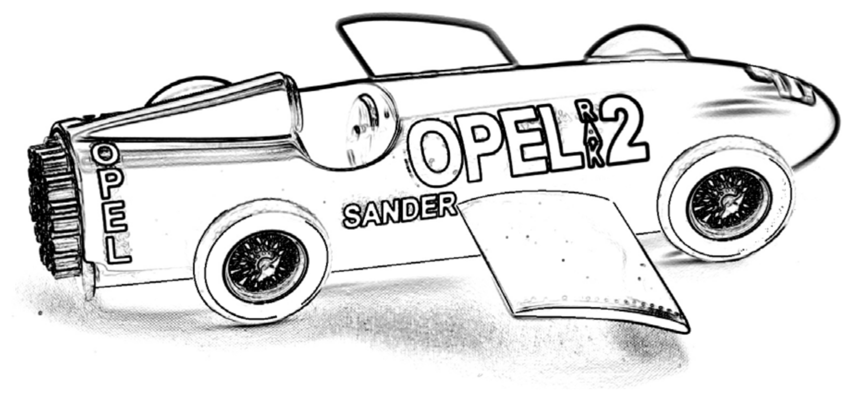
The idea of transferring aerodynamic forces from the wing to unsprung suspension parts is a solution first used by Jim Hall in the Chaparral 2F car (Figure 10). The “sky-hook” and “ground-hook” control strategies are two practical reference systems. In the case of the analysis of the dynamic systems of a car moving on uneven ground, the sky-hook strategy tracks the movement of the body relative to a fixed reference system, whereas the ground-hook strategy tracks the movement of the wheel relative to the momentary positions of the uneven changing position of the ground over time. The former is used to control body vibration and minimize it, i.e., for driver and passenger comfort, and the latter is used to control wheel tire deflection and minimize it.
The wing angle of attack setting controller linearizes the aerodynamic characteristics of the wing. The servo had a frequency response of up to 10 Hz.
A sine-sweep excitation with a wide frequency band was adopted as the excitation of the system by the road irregularities. As a second excitation model, a white noise filtered road roughness waveform was adopted using International Roughness Index (IRI) values in the Paterson standard [24]. The IRI mathematically summarizes the longitudinal surface profile of the road in a wheel track, representing the vibrations induced in a typical passenger car by road roughness.
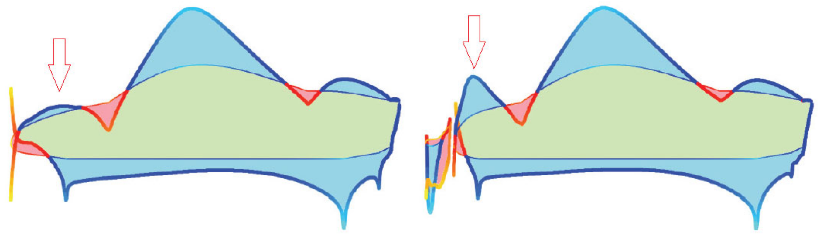
When considering the influence of active aerodynamic elements on body dynamics, the authors presented the results of analysis on comfort and road holding diagrams (Figure 17), representing the relationship between two main performance criteria: the comfort oriented index and the road holding oriented index. Lower values of either of these indices indicate a better solution.
The comfort index describes the normalized ratio of vertical body accelerations to accelerations resulting from the road profile. It focuses on accelerations in the 3–10 Hz band. Road grip, on the other hand, is evaluated by taking tire deflection into account.
Analysis of the performance of mechanical damping systems alone shows that road holding cannot be increased without affecting ride comfort by changing only the mechanical parameters of the suspension.
The authors tried to show on these diagrams that an increase in ride comfort can be achieved by using active aerodynamic elements without a reduction of the road holding parameter. They showed that the two parameters are interrelated, and that it is not possible to increase road holding by changing shock absorber damping without compromising the comfort index. This study proved that the use of actively controlled aerodynamic surfaces, with lift force being an external force that acts directly on the chassis, can alleviate this trade-off. The authors also defined limits of the actuator frequency bandwidth taking into account the actuator power.
The influence of the wing area is important. Even the introduction of a small wing area of 0.05 m2, i.e., a wingspan of 1 m and a chord of 5 cm, results in a significant drop in the comfort index (a reduction of the sensation of body vibrations). The optimal size is 0.15 m2. The results of the analysis in the time domain show that, for wings with a bigger surface, the angular changes of the wing are smaller and occur more slowly. The effectiveness of the system increases linearly with the speed of travel. The main reservation for this analysis is the fact that it is impossible to use movable wings in the front part of the vehicle.
The use of active aerodynamic elements on the car body can be beneficial in reducing the level of vertical vibration of the body when using one element per wheel controlled independently. The areas of the individual wings are of the order of 0.15 m2 (1 m × 0.15 m). The operating frequencies of the servos range from 5 to 20 Hz. The upper frequency is limited by the required servo power.
The main conclusion is that improving ride comfort using aerodynamics is possible and is not related to the reduction of the road holding of the tires.
An interesting and novel approach to the subject can be found in the paper by Wu and Chen [25]. The authors used separate wings to transfer the aerodynamic forces to the body and to the wheels separately, but simultaneously (Figure 18).
Previously, the transmission of aerodynamic forces through movable aerodynamic elements was considered, either to the vehicle body or directly to the vehicle wheels. The authors proposed using both solutions simultaneously. Each airfoil could be controlled so that body vibrations could be damped in parallel while maintaining good contact between the tires and the rough roadway. The authors gave this concept the name dual active aerodynamic surface (DAAS) control.
The dynamic model is very simple because it is limited to a quarter model of the vehicle. For comparison purposes, the authors simulated the operation under identical conditions of passive suspension (PS) and active suspension (AS) and compared the results.
To obtain sufficient values of changes in aerodynamic forces, it is necessary to use moving aerodynamic elements with a large surface area or to limit the operation of this system for high driving speeds. The authors made an assumption, which was not very realistic, that the surfaces of the airfoils would be as large as 0.6 m2 (dimensions 0.6 m × 1 m).
Simulations showed that DAAS can significantly improve ride comfort and road holding compared with PS, but only slightly when compared with AS, and can respond faster than AS and PS. The biggest drawback of this solution is the need for moving aerodynamic elements with very large areas (0.6 m2).
Unfortunately, the use of the simple (quarter car) mechanical model limited the usefulness of the conclusions.
In the work of Shahein et al. [26], the authors used a half model of a car with a single airfoil to present an active system for damping the oscillatory longitudinal vibrations of the car (Figure 19).
This paper describes the vehicle dynamics model used and the control system scheme, and presents the results obtained from the simulation of the car motion on a sinusoidal ground.
The results are presented in the form of time traces of vertical displacements of the body, vertical accelerations, angular accelerations, and tire deformation magnitudes.
The summary results are presented in a road holding index versus the comfort index graph. They indicate the possibility of a significant improvement of driving comfort using relatively small areas of moving aerodynamic elements. Unfortunately, this effect occurs only after the speed exceeds 200 km/h. Therefore, the authors used small aerodynamic surfaces this time, but only at high speeds.
Only one wing was used on the rear axle. This does not provide separation of damping of the vertical body vibrations nor of the pitch angle oscillations.

3.2.3. Models Controlling Vehicle Handling, Ride Comfort, and Road Holding (Half Car Models)
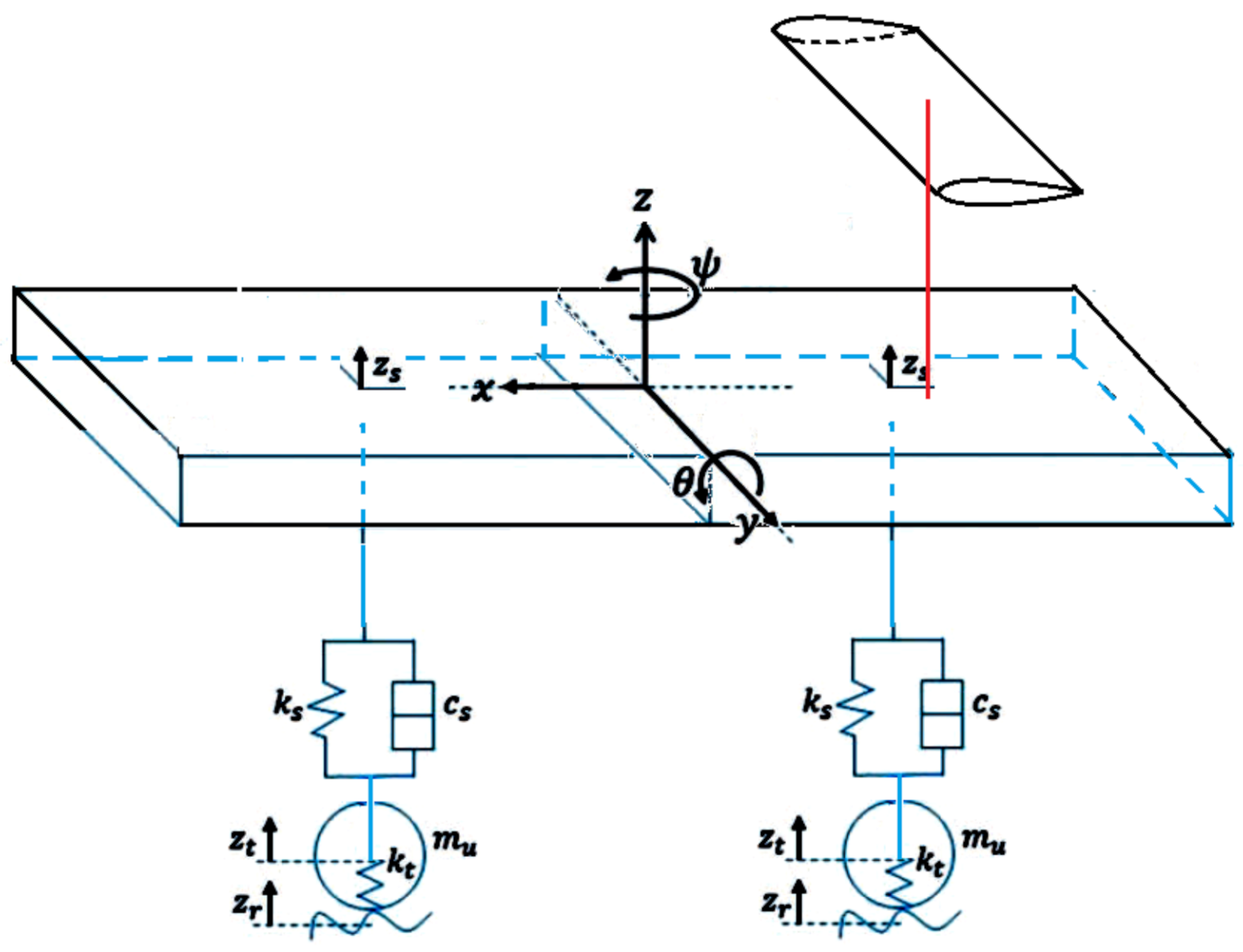
Savkoor and Chou [27] presented the possibilities of damping car body vibrations by active systems using moving aerodynamic elements (wings or spoilers) to generate damping forces (Figure 20 and Figure 21). A 3DOF vehicle model (a bicycle model) for the control of lateral, yaw, and roll motion was used. On this background, an additional dynamic model of pitching and bouncing was applied.
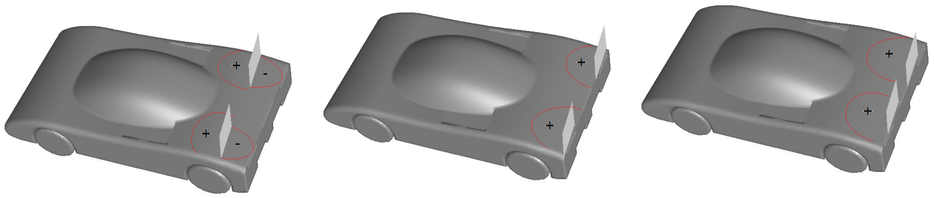
A sensible system of movable aerodynamic elements located on the car body was shown (Figure 20), their properties were analyzed, and the potential range of applications were presented. The problems that arose were discussed and methods of their solution through a control system were presented.
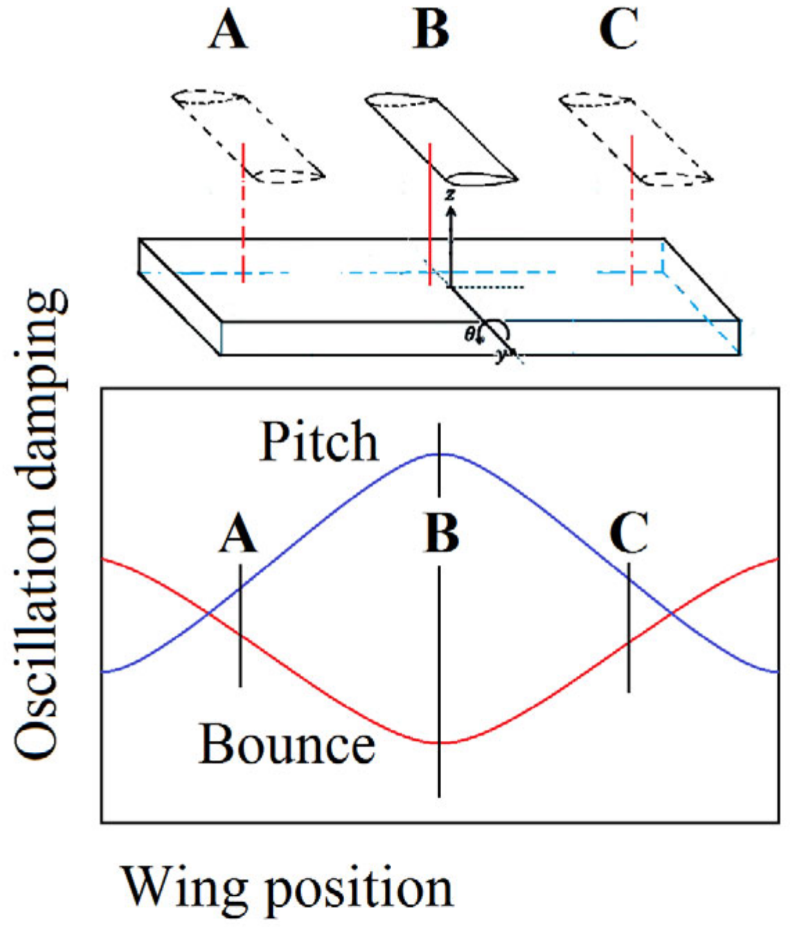
One problem considered was the position of the wing on the fuselage. When considering the influence of the position of the movable aerodynamic element on the improvement of driving comfort, it should be considered that vibrations in the vertical direction require a different position of the aerodynamic actuator than when the purpose of the action is the damping of body oscillations. A diagram showing damping effectiveness vs. aerodynamic actuator position along the longitudinal axis of the car is presented in Figure 21. Despite the relatively simple vehicle dynamics model (bicycle in plain motion and half car model of pitching and bouncing), the authors obtained a set of interesting data.
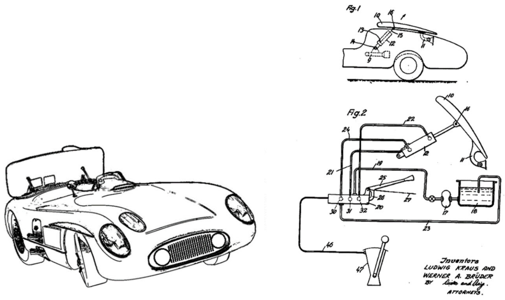
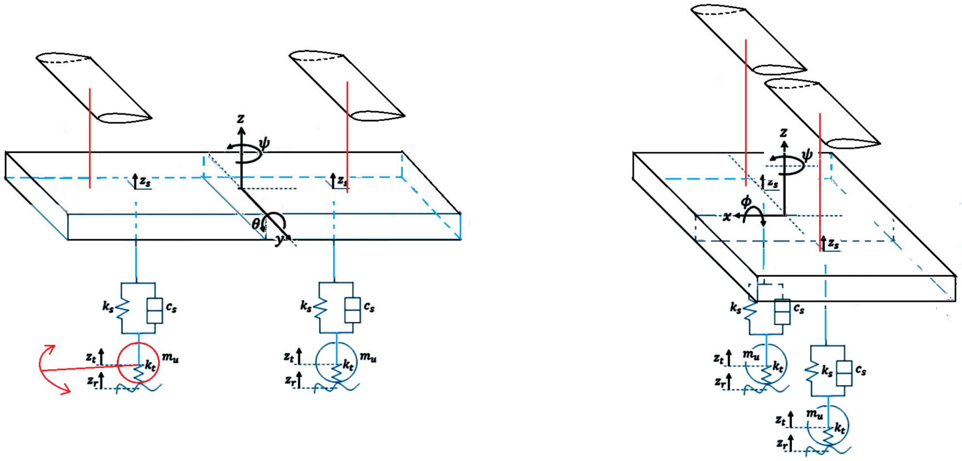
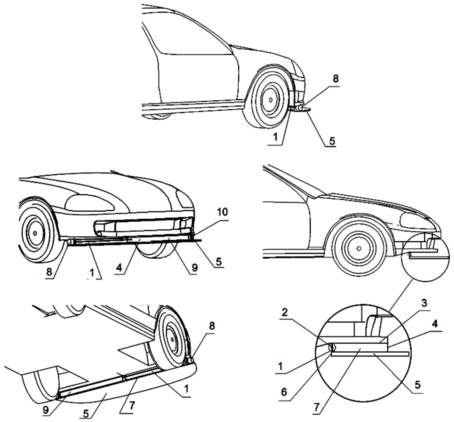
The limitations in steering range and speed that occur at high speeds can be compensated for by automatic correction systems using actuators to control the moving aerodynamic components. The main problem arising here is that the operating speed of the aerodynamic elements needs to be high. The authors make certain assumptions about the design and geometry of these elements (Figure 22). The technical implementation of such elements appears to be a difficult technical problem. Other, unconventional ways of generating large and rapid changes in aerodynamic forces would be required.
An actively controlled wing mounted on a car can enhance ride comfort without influencing road holding performance. Therefore, the active wing device solves the conflict between ride comfort and road holding. The achievable ride comfort improvement increases progressively with increasing vehicle speed. However, the bandwidth of the wing actuator also plays an important role in achieving this performance. The design of the actuator rotating the wing will require special attention to attain a high frequency bandwidth and good overall system performance. Furthermore, the use of a single wing will always be accompanied by a trade-off between pitch and bounce enhancements. An extra active wing might solve this conflict.
The wing counters the motion caused by the irregularities of the road surface. Aerodynamic forces resulting from the body motion have to be included in the ride comfort analysis, because at high speeds these forces have the main effect on ride comfort but not on road holding.
The subsequent works of Ahmad et al. [28,29], conceptually similar to the work of Corno et al. [22], based on a slightly more complicated mechanical model (half car model) interpreted once as transverse and once as longitudinal (Figure 23), presented further positive conclusions on the effects of using automatic control systems of moving aerodynamic elements.
Two models were used independently to show improvement in ride comfort and improvement in vehicle handling and road holding ability during circle driving and lane change maneuvers resulting from the application of aerodynamic forces.
Car motion in two perpendicular planes (pitch and roll motion) were considered separately using the same kinematical model with different parameters.
Since previous research has shown that the conflict between the expectation of high ride comfort and vehicle adhesion to the road cannot be resolved by selecting mechanical damping parameters, it is necessary to look for other solutions. One solution is to use movable aerodynamic elements controlled in an appropriate manner by the vehicle dynamics control system. In this study, the car motion in two perpendicular planes (tilt angle and roll angle) was analyzed independently using the same kinematic model with different parameters.
The models discussed are much simpler than those presented in earlier works and the authors’ efforts were mainly focused on other systems for controlling the motion of aerodynamic components.
The aerodynamic characteristics of moving aerodynamic elements are still only an array of elementary properties of airfoils.
The presented results also indicate the possibility of improving the dynamic characteristics of the car by the controlled movement of the moving aerodynamic elements.

3.2.4. Models Controlling Vehicle Handling, Ride Comfort, and Road Holding (Full Car Models)

Ahangarnejad and Melzi [30] proposed the addition of two individually controlled airfoils, front and rear, for the controlled generation of external aerodynamic forces to improve the dynamic stability of the car (Figure 24). The behavior of a sports car is described using its dynamic model with 14° of freedom with an automatic control system for the angle of attack of the moving aerodynamic components. The purpose of the airfoil angle control system is to achieve the desired distribution of the car’s wheel forces leading to increased driving safety. The authors used the elementary aerodynamic characteristics of the airfoil to determine the instantaneous values of aerodynamic forces stored in the form of arrays.
The control system used signals that can be easily measured in the vehicle. These are lateral acceleration, vehicle rotation speed relative to the vertical axis, and vehicle speed. The control system attempts to zero out the difference between the product of the vehicle speed, the yaw rate, and the lateral acceleration. Changes in the aerodynamic distribution of the downforce of the airfoils on the front and rear axles affect the drift angles of the wheels and change the yaw rate.
To demonstrate the effectiveness of the control system, several typical maneuvers such as slow ramp steering, lane change maneuver, fishhook, and step steer were simulated for the vehicle with active and passive systems. The maneuver conditions were chosen so that the tires operated at the slip limit. Graphs of the time variation of the yaw rate, lateral acceleration, and lateral slip angle were presented. Similar comparisons were also presented for a lane change maneuver performed on wet asphalt (tire adhesion coefficient 0.6). It was shown that the use of the proposed control system improves the stability of the vehicle also under low tire adhesion conditions.
The two (0.2 m × 1.3 m) wings used on a vehicle about 4 m long do not seem excessive. The authors did not consider changes in the aerodynamic characteristics of the wings and body resulting from their interaction. Driving speeds were high.

3.2.5. Control Models Using Full Aerodynamic Information (Vehicle Models)

An extremely advanced and mature method for analyzing the performance of moving aerodynamic components was presented by Savkoor et al. [31].
A complicated dynamic model (Figure 25) and realistic CFD modeling of flow around the truck cabin in a virtual wind tunnel with a single moving airfoil and two airfoils enabled the coupling of the real aerodynamic characteristics of the moving aerodynamic elements with the dynamics model of the cab flexibly suspended on the truck frame.
The position of the movable aerodynamic element when complex forms of cabin vibration are present has a significant effect on their damping. Unfortunately, one moving element, depending on its position, can effectively damp only one of the vibration components. The solution was to use two airfoils located near the front and rear edge of the cabin roof. The range of change of attack angles of both airfoils is within their linear characteristics. The whole system of the cabin and the rest of the vehicle is excited by the modulated road irregularities.
Using CFD techniques, the actual aerodynamic characteristics of the airfoil at different angular settings were calculated considering the influence of cabin drag. These data were input into the cabin dynamics model.

3.2.6. Aerodynamic Models of Full Vehicles with Movable Aerodynamic Components

The first numerical models of full vehicles with moving aerodynamic components were probably presented by Kataoka et al. [
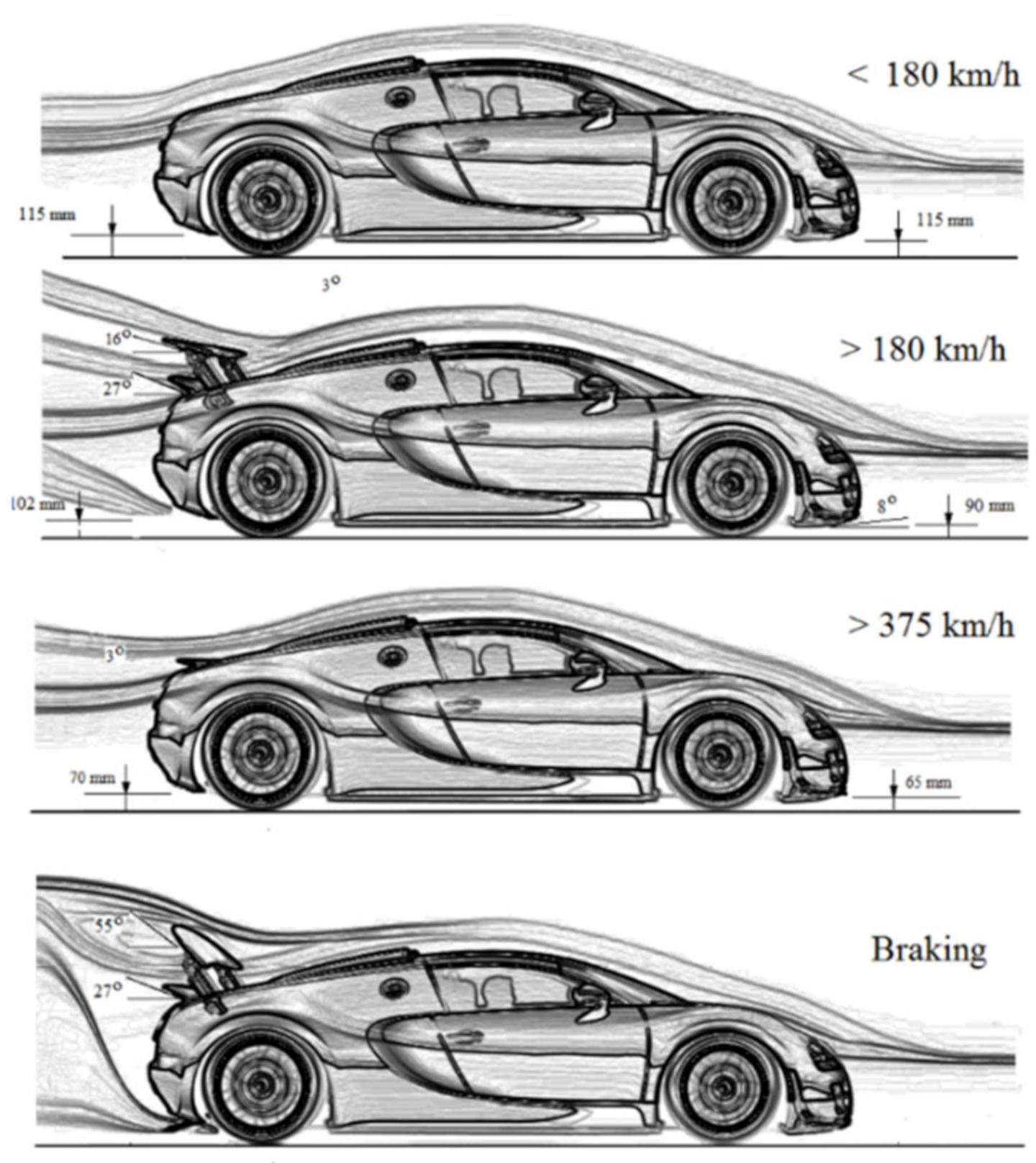
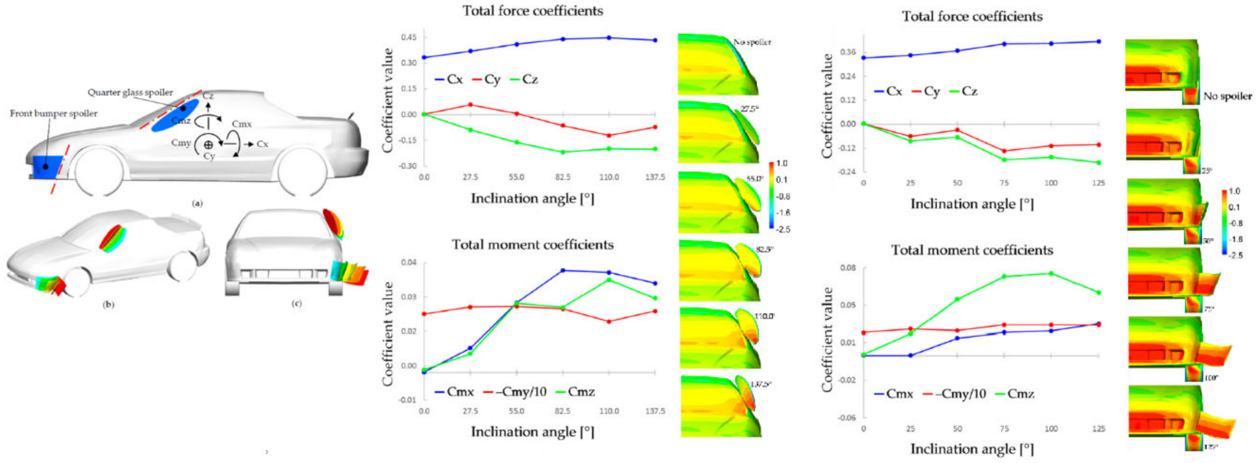
32]. This was also the first paper describing the principles of the use of movable aerodynamic elements in various driving conditions (acceleration, cornering, and braking) while providing information on their effect on the aerodynamic characteristics of the vehicle. In this work, the results of numerical and experimental research carried out in a wind tunnel and ending with the construction of the experimental vehicle HSR II were presented.
CFD numerical simulations were performed and aerodynamic characteristics were obtained, confirmed by the results of wind tunnel tests of two cars equipped with aerodynamic control devices, the experimental research car HSR II, and a production vehicle, the Mitsubishi 3000GT.
A characteristic feature of the HSR II was the use of a number of movable aerodynamic elements to change its aerodynamic characteristics to match the current road conditions. The following were mounted on the vehicle: a chin spoiler, two retractable canard wings, two independently controlled flaps, and a rear under flap. The flaps could be swung by an angle of 20° or 30°.
The paper presented the results of tests performed in three driving conditions.
In the high-speed curve driving condition, all individual movable aerodynamic components were active. In contrast, the canard wings and flaps present in the pair were activated only on the car side on the inside of the curve. The flap was turned by 20°.
The experiment showed an increase in the drag coefficient of 0.095, an increase in the downforce coefficient of 0.11, and an increase in the side force coefficient of 0.02 in this configuration compared with the configuration without active aerodynamic elements. During acceleration, the chin spoiler was extended and the drag coefficient increased by 0.01 with a 0.02 increase in the downforce coefficient. During braking, all elements were active, which caused the drag coefficient to increase by 0.21 and the downforce coefficient by 0.42. Both flaps were rotated by an angle of 30°.
A comparison of the numerical and experimental results showed that the numerical calculations significantly underestimated the aerodynamic drag coefficient and slightly overestimated the aerodynamic downforce.
The previous version of the HSR I vehicle had a chin spoiler and a single movable flap at the rear of the body. Drawings of the HSR II and HSR I vehicles are shown in Figure 26.
Some solutions of movable aerodynamic elements were used in the design of a series production vehicle. The Mitsubishi 3000GT VR4s from 1991 to 1996 were equipped with an Active Aero system consisting of a front air dam and a rear spoiler. The shaped air dam, when lowered, created a channel under the front of the body equivalent to a Venturi nozzle, generating in this area a pressure drop and a resulting downforce. A properly shaped air dam caused a pressure drop but did not cause flow separation nor an increase of aerodynamic resistance, which normally occurs behind a classical air dam design.
The study showed that when driving a car equipped with an aerodynamic package, the driver is less likely to make large corrections to the direction of the vehicle.

3.2.7. Coupled Mechanical-Aerodynamic (FSI) Models

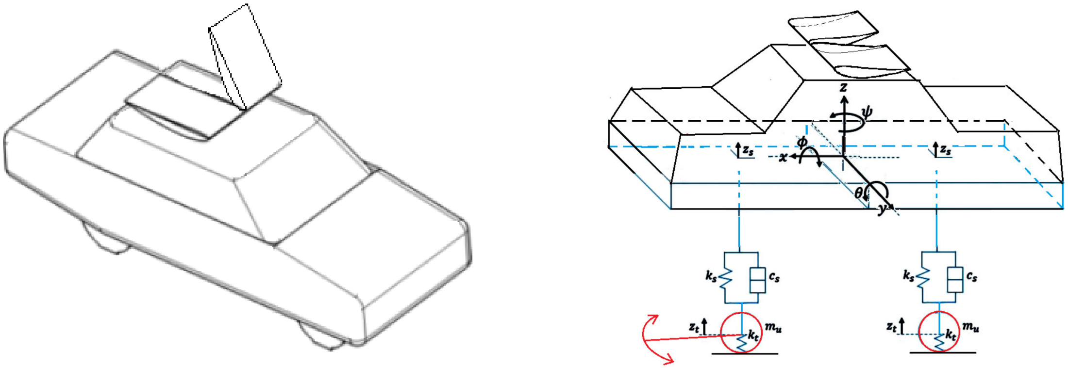
Broniszewski and Piechna [33] presented a very complex model of vehicle dynamics with time-varying aerodynamic characteristics occurring during the braking process.
In this process, the speed of vehicle motion, the position of its body located on the elastic suspension, the front and rear axle loads resulting from the action of inertia and aerodynamic forces, and the forces transmitted by tires at their contact with the road all change simultaneously. These quantities are instantaneous and interrelated. This is a typical FSI mechanical-flow coupling problem. It requires simultaneously solving the equations of motion of both the vehicle and its moving components and simulating the transient flow around its body. This requires the simultaneous use of two different simulation programs and a smooth exchange of information between them. Adams, ANSYS Fluent, and MATLAB/Simulink software were used for this purpose.
A nonlinear dynamic model of the whole car with a flexible suspension system and a movable wing, used as an aerodynamic brake, was built in a dedicated multi-body dynamic system environment: MSC. ADAMS/Car. Unsteady, realistic aerodynamic loads were obtained by CFD analysis using Fluent software. Both independent computational programs were integrated into a single ecosystem using a block diagram of a multi-domain simulation environment (MATLAB/Simulink) in which information exchange between the programs was controlled.
The complete model consists of a car dynamic model with 4° of freedom solved in the ADAMS program and a model simulating the aerodynamic properties of a vehicle with a variable geometry and time-varying position relative to the roadway realized in the ANSYS Fluent program. Both programs perform calculations simultaneously by exchanging the necessary data through MATLAB/Simulink. In this model, dynamic changes in the position of the body relative to the ground due to inertial and aerodynamic forces are taken into account.
This was the first paper to fully integrate a vehicle dynamics model with a full unsteady flow simulation model. The complex interconnection scheme between the programs was tested on an example of self-excited vibrations caused by the flow around a cuboidal beam. This is a simplified model of the famous Takoma Bridge demolished by self-excited vibrations caused by strong winds. Wind tunnel tests were performed. The mechanical parameters of the flexible beam suspension in the wind tunnel test space were measured and tests were performed during which the beam fell into self-excited vibrations caused by a cyclic vortical flow. A film recording of its movements was made. On the basis of these data, a model of the beam dynamics and a simulation flow model were created and simulations were performed using the developed system of information exchange between solvers.
A comparison of the results of the numerical simulations with the experimental data showed their complete agreement.
Such a validated scheme of relations between solvers has been used to analyze the braking process of a sports car with a movable inverted wing shifted to the aerodynamic braking position.
The decrease of car velocity occurring during braking required the adoption of a different reference system in the modeling associated with the roadway rather than the vehicle (Figure 27).
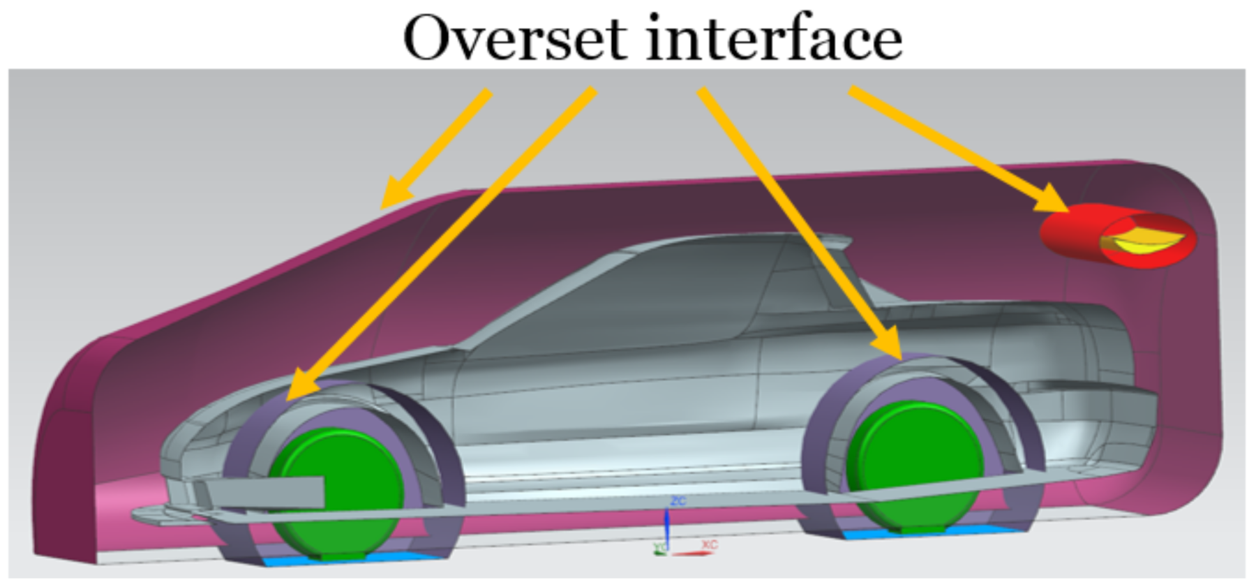
During the analysis, the entire area was moved at a speed that varied over time. To account for the motion of the car body and active aerodynamic surfaces in the simulation, the overset mesh technique was used. This technique is based on the use of meshes associated with a moving object moving on the background of the base mesh and exchanging information about flow parameters with it (see Figure 28).
The results of numerical simulations were compared with the results of track measurements, during which a number of real vehicle motion parameters were recorded. A high agreement between simulation results and experimental data was noted.
The increased efficiency of the braking process with the use of a movable aerodynamic element as an aerodynamic brake was demonstrated.
Compared to existing solutions, the primary advantages of the proposed methodology for combining different simulation environments are flexibility and robustness.
Full coupled aerodynamic-mechanic simulations were performed by Huang et al. [34]. This paper presented the results of a coupled vehicle dynamics simulation with a transient flow simulation in the presence of crosswinds. The strong influence of transient flow processes on the vehicle’s road behavior was shown. LES was used for the aerodynamic simulations, as this is currently the most accurate model of turbulent processes simulation. The vehicle model was simplified to a three-degree-of-freedom system. The driver’s reactions were included in the vehicle dynamics model. The deformable mesh method was used to account for vehicle motion.
The validation of the simulation model was performed by comparing the results of the experimental tests in a wind tunnel. Two models of vehicle motion were studied. In one model, there was full bidirectional coupling between the vehicle motion and its transient streamlining. In the other model, the coupling was unidirectional.
The analyses of the vehicle passage through the crosswind area showed smaller amplitude changes of yaw angular velocity and lateral acceleration for the full-coupled simulation compared with the one-way model. The analyses also showed the occurrence of the flow inertia effect after a fast crosswind change manifesting itself in larger amplitude changes of the lateral force and a longer recovery time.
To conclude, the significant influence of the transient flow processes on the values of the generated aerodynamic forces and the vehicle trajectory was indicated in the paper.

4. Aerodynamic Aspects of Active Control Systems

4.1. Aerodynamic Problems

A paper by Piechna et al. [35] emphasized the necessity of modeling not only the moving aerodynamic elements themselves but also the environment in which they are located, which showed how ineffective the use of wings in the front part of the vehicle body is. This paper showed a strong interaction of wings located in the front and rear part of a fast car body with flow around the body. The wings placed in front of the body are not very effective as they generate aerodynamic downforce and at the same time cause significant changes in the frontal body flow structure, resulting in the creation of low pressure areas over the body (Figure 29). This phenomenon causes the formation of a lifting force over the body there, significantly reducing the positive effect of the wing. The effectiveness of the rear wing is much higher.
An example of a car with a wing in front of the body is the Ferrari Dino 2006 Competizione. Currently, there are only a few examples of such unusual solutions. These are the Toyota TMG EV P002, built for mountain racing, and some cars used in Time Attack racing.
The results presented provide an argument against the use of moving aerodynamic elements in inappropriate body locations.

4.2. Change in Aerodynamic Lift Force by Forced Flow Separation

Increasing the rate of change of aerodynamic forces can be achieved by a route other than rotating the airfoils. Pietrzak and Piechna [36] presented the results of a numerical study on the phenomenon of forced flow separation on a wing designed to rapidly generate changes in aerodynamic forces. The purpose of this research was to establish how much change in lift and drag forces can be obtained using forced flow separation.
The analyses focused on a high lift two-element airfoil consisting of a GOE 525 airfoil as the main element, and an additional element placed at the rear to maximize the lift force. The flow detachment is forced by airflows from slots placed at different locations on both elements of the two-element wing airfoil (Figure 30) and is mainly aimed at reducing the lift force. The accompanying increase in drag is the cost of this phenomenon. The maximum value of lift coefficient Cl = 3.8 was obtained at an AOA of 21°. The aperture position and airflow velocity are the main parameters controlling flow detachment.
In addition to analyzing the changes in aerodynamic forces, the pressure distributions on the surfaces of the airfoil and the flow structures formed around the airfoil were analyzed. Two different flow detachment structures were recognized. Air injected through slots placed on the main element of the airfoil causes separation only on the main element, leaving the flow on the secondary element unchanged.
The injection of air through slots placed on the second element causes strong flow separation on both elements. Changes in the lift coefficient of 1.0 were obtained, which corresponds to a 10° change in the lift coefficient of the NACA 0012 airfoil. The large changes in lift force that can be induced very quickly, without rotating the wing, suggest the possibility of using this method in car body vibration damping systems.
In racing car designs, the use of forced lift-off leads to a decrease in the lift force of short span high lift wings and, despite the accompanying increase in aerodynamic drag, a reduction in resultant drag is achieved. This is a result of the significant reduction of induced drag occurring at the wingtips and depending on the second power of the lift coefficient. Reducing lift force reduces induced drag more strongly than increasing the resistance of the wing itself. It was noticed that there were very large changes of lift force, which would enable the use of this solution for a quick change of the lift force value in the system of active control of vehicle dynamics.

4.3. Movable Flaps

Moving flaps are simple components often used by builders. They can be found on Mercedes, Mitsubishi HSR I and II, Dodge, and Pagani Huayra. Janson and Piechna [37] presented an extensive analysis of the dynamic characteristics of various types and sizes of flaps arranged on the body of a car with a reference shape. The article presents and organizes the principles of the use of flaps.
The results of transient numerical simulations of the opening process of movable aerodynamic elements having the form of flat flaps were presented. The flaps were opened at a constant angular velocity from a resting position in the body cavities to a full 90° pivot. Arrangements of even flaps were arranged at various positions on the rear upper surface of the body of an elementary car. Changes in lift and aerodynamic drag force generated by the entire vehicle were recorded over time.
The position of the flaps on the vehicle had an extremely significant effect on the maximum values of the forces obtained. Flaps placed far from the rear edge of the body, placed close to the side edges of the body, and flaps located near the axis of symmetry of the vehicle generate significantly smaller values of aerodynamic downforce.
The calculation results were divided into two groups (Figure 31). One group consisted of flaps rotating around the axis located near the front edge of the flap. The second group consisted of flaps rotating around axes located near the rear edge of the flap. The location of the axis of rotation had a significant effect on the changes over time of the generated aerodynamic forces. The changes in forces generated by the flaps rotated around the front edge were characterized by nearly linear changes in forces.
For flaps rotated about the rear edge, there were strong nonlinearities in the force changes. Initially, at small deflections of the flaps (less than 20°), there was reattachment of the flow to the outer surface of the flaps resulting in the generation of only small aerodynamic forces. At larger rotation angles, the flow detachment that occurred significantly increased the generated aerodynamic forces. The main mechanism of operation of the flaps comes down to the generation of a high pressure area in front of the flap and a low pressure area behind it (Figure 32). The larger the body surface area in front of the open flap and the smaller behind the flap, the greater the aerodynamic downforce generated.
As indicated by examples of the practical use of flaps as an aerodynamic brake in the Mercedes 300 SL car, the flaps can be used as very effective aerodynamic brakes. For these purposes, a configuration with the flap’s axis of rotation at the rear edge appears to be better, as both more braking force and more downforce are generated, plus the force acts more to the rear, increasing the aerodynamic moment and thus resulting in more aerodynamic downforce on the vehicle’s rear axle.
The best placement for the flaps is the rear edge of the vehicle. This solution was used in the Porsche 908 and 917 cars (Figure 8). Flaps pivoted outside the vehicle give the highest force values in relation to the flap surface, and force changes are smooth. Under certain driving conditions, they allow a slight reduction in aerodynamic drag.
Flaps can be used as active elements to dampen body movement. In this case, flaps located at the front of the body with a forward pivot position should be used because of the smooth and almost linear characteristics of the aerodynamic downforce. Flaps are used quite often in passenger car design and beyond. The Pagani Huayra car has movable flaps at the rear and front of the body.

4.4. Movable Supporting Flaps

Kurec et al. [38] proposed the specific use of a small movable element in the form of a flap placed on the body under the airfoil which interacts with it (Figure 33). The search for solutions and features of small moving aerodynamic elements located in places sensitive to changes of flow structure was the main objective of this paper. Both CFD numerical computation techniques as well as experimental tests in a wind tunnel of a 1:2.5 scale car model were used. They noted that placing a small movable element in the form of a plate or a spoiler under the rear part of an inverted wing, which pressed the rear of the car down, was a very effective way to increase the aerodynamic downforce. The aerodynamic characteristics of a car with an inverted wing, generating aerodynamic downforce as a function of its angle of attack, were studied. After adding a small movable aerodynamic element at the rear edge of the trunk lid, under the wing, it was found that the aerodynamic effects of its 55° rotation corresponded to the effects of a 15° rotation of a much larger wing.
During the numerical study, the feasibility of using several different turbulence models was tested by comparing the obtained results with each other. The results the of numerical calculations were verified by comparison with the results of the tunnel tests. A good agreement was obtained.
The discovery that the rotation of a small movable aerodynamic element placed in the right place on the car body can generate forces typically obtained by many times larger aerodynamic elements opens new possibilities for the use of active systems of vehicle aerodynamic damping. Such small and effective elements are ideal for aerodynamic actuators in automatic systems.

4.5. Movable Gurney Flaps

The Gurney flap is a small but extremely effective element that increases the value of a wing’s lift. Zerihan et al. [39] presented the experimental results of a one-element inverted wing with a high-lift profile equipped with a Gurney flap. The research was concerned with the behavior of the wing near the ground. The experimental results describing the aerodynamic downforce and aerodynamic drag as well as descriptions of the flow structure were presented. The wing in this configuration is equivalent to the front wing in open-wheel racing cars. The aerodynamic characteristics of the wing placed close to the ground and far from it were compared. Analogies and differences were pointed out.
Figure 34 shows excerpts from the test results presented in [39]. The figure was supplemented with diagrams to facilitate its interpretation. The wing without the Gurney flap and with the flap were studied. Two configurations were studied. In one configuration, the wing was located far from the ground (hr/c = 1) and the changes of lift force were obtained by changing its incidence. In the other configuration, the inclination of the wing was constant at −1°, while the lift force increased with the decreasing distance between the wing and the moving ground. It was shown that a Gurney flap placed on the wing operating close to the ground has a much higher lift than the one placed on the wing operated far from the ground. One concept of the rotating Gurney flap is shown in Figure 35.
The flow detachment in the gap between the wing and the ground causes a non-steady separation region, which significantly deteriorates the aerodynamic properties of the wing. This means a decrease in downforce and an increase in aerodynamic drag force.
The lift generated by the Gurney flap depends only on the lift coefficient and not on the aerodynamic profile of the wing. Moreover, this coefficient depends on the angle of attack of the wing or the wing ride height. A reduction of the wing distance to the ground dramatically increases the influence of the Gurney flap. This was possible only for the front wing.
Basso et al. [41] presented the results of a detailed CFD analysis on a vehicle configuration representative of an F1 car, and these results were used to investigate the effects of Gurney flap installations on the flow structure and on component performances. It can be observed that the addition of this small device had a dramatic effect on the overall flow structure around the car. The flow structure from the front wing affected by the GF will interact with other car components with evident aerodynamic performance changes with respect to the baseline configuration. The overall front wing downforce increased by almost 24%, while the drag force increase was 28%.
The stationary Gurney flap is a very effective solution and its use in the form of a rotating plate that activates in one position and deactivates in another can be undertaken with high frequency. Due to its small dimensions and mass, the rotating Gurney flaps can be very fast and effective aerodynamic actuators. A patent has been applied for this solution [40]. The results confirm the hypothesis that the application of the Gurney flap as an active control element is efficient.

4.6. Movable Vortex Generators

Katz [42] presented the operation of vortex generators, which in some cases can be used as fast and efficient generators of variable aerodynamic forces, particularly in the area of the chassis in the front part of the vehicle.
Figure 36 presents excerpts from the test results presented in [42], indicating a very high value of lift coefficient reachable at a very low clearance between the ground and the vortex generator edge. Opening or closing the vortex generator plates can produce large changes in lift. The generated aerodynamic force also depends on the size of the surface, being high for large surfaces, even if the change in the lift coefficient is not large. The vortex generators themselves may be small, but the effects of their use occur over a large area. Therefore, the force values can be significant. This solution could be an interesting substitute for a moving wing.

4.7. Movable Blocking Flaps

Splitters located in the low front part of the car fuselage can be activated and deactivated by the use of a rotary blocking flap. Such an idea is presented in Figure 37. There is a small slit (marked as 7 in Figure 37) between the splitter and the car body, which can be opened or closed by rotating the blocking flap (marked as 1 in Figure 37). The element marked 2 in Figure 37—is an axis of the rotating blocking flap marked 1. Opening the gap reduces the downforce generated by the splitter, while closing the gap increases it. The practical frequency bandwidth of such an aerodynamic actuator is in the range of 20 Hz.
A patent was applied for this solution [40].

4.8. Movable Side Force Aerodynamic Actuators

In addition to classical wings with airfoils, there are other elements that can be used as generators of variable aerodynamic forces. The influence of side spoilers on the aerodynamic properties of a sports car was also considered.
Kurec and Piechna [43] presented the possibilities of generating, besides changes in aerodynamic drag force and lifting force, a lateral force by asymmetrically opened movable aerodynamic elements. In Figure 38, basic information is presented making it possible to assess the possibilities of the practical application of the considered moving aerodynamic elements in automatic control systems.
The spoiler located on the A-pillar at higher deflection angles generates a significant aerodynamic downforce (coefficient Cz = −0.2) and a small lateral force (Cy = −0.1). A small yaw and pitching moment are generated. Its effect is not only due to the forces generated on it, but also due to the creation of an area of increased pressure on the windscreen and an area of reduced pressure on the side window. The tilting side flap located in front of the front wheel operates in a similar manner.

4.9. Flexible Elements Generating Aerodynamic Downforce

Flexible components, which can deform as a result of pressure differentials due to body flow or which can utilize compressed gas sources located on board the body, can be active actuators of aerodynamic systems.
Tudruj et al. [44,45,46] developed a model of dynamically developed elastic shells to simulate the operation of airbags, which was used to model statically and dynamically deformable elements of a sports car body [47]. Flexible elements (Figure 39) can be efficient and fast-reacting aerodynamic actuators in the proper configuration.

5. Summary and Conclusions

The presented papers concerning the application of control systems to activate movable aerodynamic elements were written by specialists in control system analysis, and they treat aerodynamic elements very theoretically. They assumed that there is no interaction between the car body and the wing located near the car body. Unfortunately, this is not the case. This assumption is enough to show the scheme of operation of the control system, but drawing conclusions on this basis is not correct.
It can be concluded that classical methods for the rapid generation of time-varying aerodynamic forces are insufficient. Classical airfoils require either large surfaces or very high motion speeds to achieve the force magnitudes expected by designers of automatic control systems. This means that other aerodynamic solutions must be sought out.
Present day problems related to time-varying aerodynamic forces and their effect on vehicle dynamics have had some solutions in the past. They are often technical solutions based mainly on the intuition of engineers. There are better and worse solutions, and these experiences should be used.
Taking into account the results presented by many authors, the use of active aerodynamic elements on a car body can have a beneficial effect on reducing the level of vertical vibrations of the body and increasing driving safety. Actively controlled wings mounted on a car can have the potential to increase driving comfort without compromising driving characteristics.
The presented and discussed works belong to three subgroups of control systems. These are systems that improve driving comfort by reducing body vibrations, systems that improve driving safety while performing maneuvers on the road, and systems that improve both driving comfort and safety. The first two differ significantly in the speed requirements of the moving aerodynamic components.
Analyzing the state of the art in modeling control systems for moving aerodynamic components used to increase the safety margin of high-speed driving and maneuvers on the road, there is a large gap between models of control systems and their aerodynamic actuators. Researchers involved in building controller models adopt unrealistic models of aerodynamic force generation.
Usually, new control concepts are presented based on very simple quarter car models. Rarely are half car models used in the longitudinal or transverse plane. Only a few studies present solutions based on a full car model. With few exceptions, researchers dealing with the control systems of moving aerodynamic elements pay little attention to the real flow phenomena occurring during fast driving of a vehicle. Typically, moving aerodynamic components are treated in a simplified manner. This is sufficient for the presentation of the controller scheme, but it does not reflect the technical feasibility of their implementation. They use simple models of wings with aerodynamic profiles, which in reality, in the presence of the car body and their fast angular motion, have different aerodynamic characteristics.
Current studies indicate that there are some performance improvement trends, but they do not lead to realistic solutions. The main problem in developing an effective way to use moving aerodynamic elements in automatic damping systems is the design of high-speed actuators. Designers typically use moving parts with large surface areas, which require powerful actuators.
In several studies, nonstationary effects were manifested by the presence of flow inertia. The designers of control systems of moving aerodynamic elements requiring rapid changes of their position must consider the delays in their response resulting from the flow inertia. This requires much more sophisticated models of force generation by these elements.
The aerodynamic characteristics of movable aerodynamic elements alone do not reflect their actual properties when mounted on a car body. This is especially true for movable aerodynamic elements designed to operate at the front of the body. The elements themselves generate aerodynamic forces, but these are compensated for by changes in the body flow structures behind them. In summary, generating vertical forces at the front end of a vehicle is difficult.
Despite the passage of time, researchers involved in building systems to automatically control additional moving aerodynamic components still use very simple models of aerodynamic moving components. The best work was undertaken many years ago. The vehicle dynamics models themselves are also relatively simple.
It is necessary to model the flow field around the entire body on which the moving aerodynamic elements are mounted. Simply modeling the aerodynamic characteristics of the moving aerodynamic elements is not sufficient.
On the other hand, there are already models being developed by experts in vehicle aerodynamics that combine models of transient vehicle motion with models of transient flow and the motion of moving aerodynamic components, but without models of control systems.
There are a number of aerodynamic solutions capable of generating variable aerodynamic forces that are faster and more efficient than commonly used airfoils. There appears to be a need for collaboration between aerodynamicists and control system developers to make the proposed solutions more realistic.
Moving aerodynamic elements are not intended to directly reduce the energy required to drive the car; their effect is indirect.
The travel time can be shortened by increasing the average speed. Therefore, the energy consumption of energy-consuming components can be reduced, which are dependent on the travel time and not the speed. Such components are lighting, heating, or cooling, and partly the driving, provided that the maximum speed does not increase. The bends can be taken at a faster speed, i.e., in less time, by temporarily increasing a vehicle’s downforce on the road due to the activation of moving aerodynamic elements on the bends. Despite the higher speed on a curved road, the passage is still safe due to the ability of the tires to achieve higher lateral forces. Corners are usually taken slower by braking before the turn and accelerating out of the turn. In both cases, extra energy is used. The average speed can be increased without an increase in fuel consumption at top speed when cornering faster. Thus, the proper use of moving aerodynamic elements at times when they are needed can reduce the energy consumption needed to negotiate a curvy road. This is especially important for electric cars that use limited electricity sources to heat or cool a vehicle and to power it.
However, there are already solutions that directly reduce the energy consumption required for fast driving. In the hybrid Mercedes-Benz Concept IAA (Intelligent Aerodynamic Automobile), eight segments extend from the rear end of the vehicle when travelling above 80 km/h, extending the body by 39 cm. The front end changes and the wheel covers change from concave to convex. The aerodynamic drag coefficient drops from 0.25 to 0.19 [48].

Funding

This research received no external funding.

Institutional Review Board Statement

Not applicable.

Informed Consent Statement

Not applicable.

Data Availability Statement

Not applicable.

Conflicts of Interest

The author declares no conflict of interest.

References

  1. Yu, W.; Gao, W. A Review of the influence of active aerodynamic tail on vehicle handling stability. FMIA 2021 J. Phys. Conf. Ser. 2021, 1985, 012017. [Google Scholar] [CrossRef]
  2. Gao, W.; Kong, X.; Deng, Z.; Yu, W.; Wu, Y.; Luo, J. Review of state of the art in active aerodynamic control research for vehicles. FMIA 2021 J. Phys. Conf. Ser. 2021, 1985, 012040. [Google Scholar] [CrossRef]
  3. Available online: http://greyfalcon.us/Mercedes%20T80.htm (accessed on 10 October 2021).
  4. Available online: https://drivemag.com/red-calipers/90-years-ago-opel-built-and-raced-a-rocket-car (accessed on 30 August 2021).
  5. Ludwig, K.; Bruder, W.A. Aerodynamic Braking Mechanism for Motor Vehicles. US Patent 2932370A, 11 June 1956. [Google Scholar]
  6. Falkovén, A.; Nordin, J.; Rama, K.; Rask, A.; Sjöstrand, P.; Stadler, M. CFD-Analysis of the Aerodynamic Properties of a Mercedesmercedes-Benz Benz 300SLR. n.d. Available online: https://publications.lib.chalmers.se/records/fulltext/219318/219318.pdf (accessed on 19 August 2021).
  7. Schuetz, T.C. Aerodynamics of Road Vehicles, 5th ed.; SAE Inter-National: Warrendale, PA, USA, 2015. [Google Scholar] [CrossRef]
  8. Gullberg, P.; Löfdahl, L.; Qiu, Z. Influence of aerodynamics on the fatal crash in Le Mans 1955. In Proceedings of the 4th European Automotive Simulation Conference, Munich, Germany, 6–7 July 2009. [Google Scholar]
  9. Gullberg, P.; Löfdahl, L. The Role of Aerodynamics in the 1955 Le Mans Crash; SAE International: Warrendale, PA, USA, 2008. [Google Scholar] [CrossRef]
  10. Available online: https://simanaitissays.com/2016/06/15/porsche-aerodynamics/ (accessed on 10 October 2021).
  11. Available online: https://en.wikipedia.org/wiki/Chaparral_Cars (accessed on 10 October 2021).
  12. Hall, J.E.; Mrlik, J.R.; Musser, J.G.; Winchell, F.J. Aerodynamic Spoiler for Automotive Vehicles. US Patent 3455594, 15 July 1969. [Google Scholar]
  13. Mezger, H. Der Porsche 4,5-l-Rennsportwagen Typ 917, Teil 2, ATZ, BD; 1969; Volume 71, pp. 417–423. Available online: https://presskit.porsche.de/museum/en/2019/topic/anniversaries/porsche-celebrates-50-years-of-the-917/hans-mezger-the-porsche-917-chief-engineer.html (accessed on 15 September 2021).
  14. Hucho, W.-H. (Ed.) Aerodynamics of Road Vehicles, 4th ed.; SAE International: Warrendale, PA, USA; Materials Park, OH, USA, 1998; p. 918. [Google Scholar]
  15. Lamar, P. Aerodynamics & The Group Seven Racing Car. In Proceedings of the AIAA Symposium on The Aerodynamics of Sports & Competition Automobiles, Los Angeles, CA, USA, 20 April 1968. [Google Scholar]
  16. Available online: https://www.bugatti.com/models/veyron-models/technology/ (accessed on 10 October 2021).
  17. Donicelli, C.; Mastinu, G.; Gobbi, M. Aerodynamic effects on ride comfort and road holding of automobiles. Veh. Syst. Dyn. Suppl. 1996, 25, 99–125. [Google Scholar] [CrossRef]
  18. Diba, F.; Barari, A.; Esmailzadeh, E. Dynamic performance enhancement of small size racecar using active inverted wings. In Proceedings of the Canadian Society for Mechanical Engineering Congress, Winnipeg, MB, Canada, 4–6 June 2012. [Google Scholar]
  19. Pacejka, H.B.; Bakker, E. The Magic Formula Tyre Model. Int. J. Veh. Mech. Mobil. 1992, 21, 1–18. [Google Scholar] [CrossRef]
  20. Diba, F.; Barari, A.; Esmailzadeh, E. Handling and safety enhancement of race cars using active aerodynamic systems. Veh. Syst. Dyn. Int. J. Veh. Mech. Mobil. 2014, 52, 1171–1190. [Google Scholar] [CrossRef]
  21. Chen, Z.; Wu, Y.; Li, F. Integrated control of differential braking and active aerodynamic control for improving high speed stability of vehicles. Int. J. Automot. Technol. 2020, 21, 61–70. [Google Scholar] [CrossRef]
  22. Corno, M.; Bottelli, S.; Panzani, G.; Tanelli, M.; Spelta, C.; Savaresi, S. Improving high speed road-holding using actively controlled aerodynamic surfaces. In Proceedings of the European Control Conference, Zurich, Switzerland, 17–19 July 2013; pp. 1493–1498. [Google Scholar]
  23. Corno, M.; Bottelli, S.; Tanelli, M.; Spelta, C.; Savaresi, S.M. Active Control of Aerodynamic Surfaces for Ride Control in Sport Vehicles. In Proceedings of the 19th World Congress The International Federation of Automatic Control, Cape Town, South Africa, 24–29 August 2014. [Google Scholar]
  24. Paterson, W.D.O. International Roughness Index: Relationship to Other Measures of Roughness and Riding Quality. In Proceedings of the 65th Annual Meeting of the Transportation Research Board, Washington, DC, USA, 13–16 January 1986. [Google Scholar]
  25. Wu, Y.; Chen, Z. Improving Road Holding and Ride Comfort of Vehicle Using Dual Active Aerodynamic Surfaces. In Proceedings of the 2nd International Conference on Robotics and Automation Sciences, Wuhan, China, 23–25 June 2018. [Google Scholar]
  26. Shahein, A.H.; Ata, A.A.; Hara, E.H.; El-Souhily, B.M. Vibration suppression of terrains irregularities using active aerodynamic surface for half-car model sport vehicles. J. Vib. Control 2020, 26, 1–15. [Google Scholar] [CrossRef]
  27. Savkoor, A.R.; Chou, C.T. Application of Aerodynamic Actuators to Improve Vehicle Handling. Veh. Syst. Dyn. Int. J. Veh. Mech. Mobil. 1999, 32, 345–374. [Google Scholar]
  28. Ahmad, E.; Song, Y.; Khan, M.A.; Youn, I. Attitude Motion Control of a Half car Model with Tracking Controller Using Aerodynamic Surfaces. In Proceedings of the International Automatic Control Conference, Keelung, Taiwan, 13–16 November 2019; pp. 1–6. [Google Scholar]
  29. Ahmad, E.; Iqbal, J.; Khan, M.A.; Liang, W.; Youn, I. Predictive Control Using Active Aerodynamic Surfaces to Improve Ride Quality of a Vehicle. Electronics 2020, 9, 1463. [Google Scholar] [CrossRef]
  30. Ahangarnejad, A.H.; Melzi, S. Numerical analysis of the influence of an actively controlled spoiler on the handling of a sports car. J. Vib. Control 2018, 24, 1–12. [Google Scholar] [CrossRef]
  31. Savkoor, A.; Manders, S.; Riva, P. Design of actively controlled aerodynamic device for reducing pitch and heave of truck cabins. Soc. Automot. Eng. Jpn. Rev. 2001, 22, 421–434. [Google Scholar] [CrossRef]
  32. Kataoka, T.; China, H.; Nakagawa, K.; Yanagimoto, K.; Yoshida, M. Numerical simulation of road vehicle aerodynamics and effect of aerodynamic devices. SAE Trans. 1991, 100, 722–734. [Google Scholar] [CrossRef]
  33. Broniszewski, J.; Piechna, J. A fully coupled analysis of unsteady aerodynamics impact on vehicle dynamics during braking. Eng. Appl. Comput. Fluid Mech. 2019, 13, 623–641. [Google Scholar] [CrossRef]
  34. Huang, T.; Gu, Z.; Feng, C.; Zeng, W. Transient aerodynamics simulations of a road vehicle in the crosswind condition coupled with the vehicle’s motion. Proc. IMechE Part D J. Automob. Eng. 2017, 232, 583–598. [Google Scholar] [CrossRef]
  35. Piechna, J.; Rudniak, L.; Piechna, A. CFD Analysis of the Central Engine Generic Sports Car Aerodynamics. In Proceedings of the EASC 2009 4th European Automotive Simulation Conference, Munich, Germany, 6–7 July 2009. [Google Scholar]
  36. Pietrzak, P.; Piechna, J. Numerical investigation of the controllable wing stall caused by the air injection. Arch. Mech. Eng. 2013, 60, 199–217. [Google Scholar] [CrossRef] [Green Version]
  37. Janson, T.; Piechna, J. Numerical analysis of aerodynamic characteristics of a of high-speed car with movable bodywork elements. Arch. Mech. Eng. 2015, 62, 451–476. [Google Scholar] [CrossRef]
  38. Kurec, K.; Remer, M.; Mayer, T.; Tudruj, S.; Piechna, J. Flow control for a car-mounted rear wing. Int. J. Mech. Sci. 2019, 152, 384–399. [Google Scholar] [CrossRef]
  39. Zerihan, J.; Zhang, X. Aerodynamics of Gurney Flaps on a Wing in Ground Effect. AIAA J. 2001, 39, 772–780. [Google Scholar] [CrossRef]
  40. Układ do tłumienia Drgań Nadwozia Pojazdu W Czasie Szybkiej Jazdy I Tylny Płat Dociskowy Z Aktywnymi Elementami Aerodynamicznymi [System for Damping the Vibrations of the Vehicle Body during High-Speed Driving and a Rear Airfoil with Active Aerodynamic Elements]. Patent P.426981, 14 July 2021.
  41. Basso, M.; Cravero, C.; Marsano, D. Aerodynamic Effect of the Gurney Flap on the Front Wing of a F1 Car and Flow Interactions with Car Components. Energies 2021, 14, 2059. [Google Scholar] [CrossRef]
  42. Katz, J.; Garcia, D. Aerodynamic Effects of Indy Car Components. Artic. SAE Tech. Pap. 2002, 111, 2322–2330. [Google Scholar] [CrossRef]
  43. Kurec, K.; Piechna, J. Influence of Side Spoilers on the Aerodynamic Properties of a Sports Car. Energies 2019, 12, 4697. [Google Scholar] [CrossRef] [Green Version]
  44. Tudruj, S.; Piechna, J. New model of the simulation of the airbag operation in the case of the out-of-position occupant-the comparison with existing models. Arch. Mech. Eng. 2003, 50, 201–223. [Google Scholar]
  45. Tudruj, S.; Piechna, J.; Dziewoński, T. Influence of the Outside Air Inertia Effect on Airbag Deployment; IRCOBI: Graz, Austria, 2004. [Google Scholar]
  46. Tudruj, S.; Piechna, J. Numerical analysis of the possibility of using an external air bag to protect a small urban vehicle during a collision. Arch. Mech. Eng. 2012, 59, 257–281. [Google Scholar] [CrossRef] [Green Version]
  47. Piechna, J.; Janson, T.; Sadowski, P.; Tudruj, S.; Piechna, A.; Rudniak, L. Sports Car with Movable Flaps and Deformable Airbags. In Proceedings of the Automotive Simulation World Congress, Frankfurt/Main, Germany, 29–30 October 2013. [Google Scholar]
  48. Available online: https://ufcnancy.info/news/mercedes-reveals-concept-iaa-shape-shifting-coupe (accessed on 10 October 2021).
Figure 1. Mercedes T80.
Energies 14 07887 g001
Figure 2. Opel RAK2 rocket-propelled vehicle.
Energies 14 07887 g002
Figure 3. Mercedes-Benz 300 SL Prototipo.
Energies 14 07887 g003
Figure 4. Mercedes-Benz 300 race car with active airbrake and patent drawing [5].
Energies 14 07887 g004
Figure 5. Michael May’s Porsche 550 Spyder car with movable wing.
Energies 14 07887 g005
Figure 6. Chaparral 2C with a large movable tailgate.
Energies 14 07887 g006
Figure 7. Chaparral 2F.
Energies 14 07887 g007
Figure 8. Porsche 917 with movable flaps and mechanism automatically responding to suspension movements.
Energies 14 07887 g008
Figure 9. Rear extendable spoiler of the Mercedes-Benz C112.
Energies 14 07887 g009
Figure 10. The rear wing of the Chaparral 2F directly transmits the aerodynamic forces to the suspension [12].
Energies 14 07887 g010
Figure 11. Rear spoiler of Koenigsegg Agera and its modes of operation.
Energies 14 07887 g011
Figure 12. Bugatti Veyron operation modes [16].
Energies 14 07887 g012
Figure 13. Complex 12DOF mechanical model of a vehicle [17].
Energies 14 07887 g013
Figure 14. A 9DOF nonlinear vehicle model [19].
Energies 14 07887 g014
Figure 15. Simplified geometry of a car (left). Model of the car and geometry of movable aerodynamic elements (right) [21].
Energies 14 07887 g015
Figure 16. A diagram of the location of active aerodynamic elements and their relation to sprung and unsprung mass [22,23].
Energies 14 07887 g016
Figure 17. Comfort versus road holding diagram: (in red) the area of improvement by the application of movable aerodynamic elements [22,23].
Energies 14 07887 g017
Figure 18. The idea of passive suspension (PS) (left), active suspension (AS) (center), and dual active aerodynamic surface (DAAS) control (right) [25].
Energies 14 07887 g018
Figure 19. Dynamic car model—simplified half car model [26].
Energies 14 07887 g019
Figure 20. Scheme of the used half car model run on an uneven road [27].
Energies 14 07887 g020
Figure 21. Influence of the aerodynamic actuator mounting position on bounce and pitch [27].
Energies 14 07887 g021
Figure 22. Schematic configurations of the aerodynamic actuators generating the required external forces and moments [27].
Energies 14 07887 g022
Figure 23. Longitudinal (left) and transverse (right) model assumptions [28,29].
Energies 14 07887 g023
Figure 24. Mechanical full nonlinear 14DOF model with aerodynamic forces application [30].
Energies 14 07887 g024
Figure 25. Mechanical model of truck dynamics with two aerodynamic actuators [31].
Energies 14 07887 g025
Figure 26. HRS II front view (chin spoiler and canard wings visible), rear view (one flap open), HSR I (single flap—aerodynamic brake visible).
Energies 14 07887 g026
Figure 27. An example of streamlines in observer reference frame colored by velocity magnitude.
Energies 14 07887 g027
Figure 28. Overset grid blocks used for moving simulation of movable car elements motion—car fuselage, movable wing, and wheels.
Energies 14 07887 g028
Figure 29. Comparison of pressure distribution at the symmetry plane of the reference shape (left) and car with the front wing (right). Color coding: red—positive pressure, blue—negative pressure. Arrows indicate the reduced pressure on the top front surface generated by the front wing.
Energies 14 07887 g029
Figure 30. A two-element profile geometry with numbers and positions of slots forcing flow separation [36].
Energies 14 07887 g030
Figure 31. Comparison of lift generation by different flaps divided into two groups (left—flaps rotating around the front edge, right—flaps rotating around back edge) [37].
Energies 14 07887 g031
Figure 32. Schematic positions of positive and negative pressure zones caused by different flap positions [37].
Energies 14 07887 g032
Figure 33. Visualization of a car model with small movable flaps located under the rear wing: deployed position (a) and extended position (b).
Energies 14 07887 g033
Figure 34. Gurney flap characteristics in freestream and ground effect [39].
Energies 14 07887 g034
Figure 35. Drawing from patent application [40].
Energies 14 07887 g035
Figure 36. Downforce generated by vortex generators in ground effect [42].
Energies 14 07887 g036
Figure 37. Front splitter blocking flap, drawing from patent [40].
Energies 14 07887 g037
Figure 38. The geometry and aerodynamic characteristics of add-ons generating a side force [43].
Energies 14 07887 g038
Figure 39. The geometry of a car with additional aerodynamic elements (side airbag curtains and airbag splitter).
Energies 14 07887 g039
Publisher’s Note: MDPI stays neutral with regard to jurisdictional claims in published maps and institutional affiliations.

