1. Introduction
Low pressure tunnel transport is an interesting and competitive alternative to road transport due to the potentially very high vehicle movement speeds and significantly reduced aerodynamic drag. The pressure level in tunnels is the main factor reducing the energy consumption for moving vehicles at very high speeds practically not possible in road transport.
In this transport mode, there are a number of specific and not very widely known aerodynamic problems not present in road transport resulting from the extremely high speeds of vehicle movement in an unusual environment. These problems translate into the emergence of unusual design solutions for the vehicles themselves, the organizational systems, and the safety systems.
In 1909, rocket pioneer Robert H. Goddard proposed the first concept of high-speed trains moving in a vacuum or evacuated tubes [
1], patented in 1950 [
2]. A very realistic continuation of this idea was presented in a project of the Swissmetro [
3,
4,
5,
6]. A modern version of the vacuum train (Hyperloop) was proposed by Elon Musk in a white paper published by SpaceX in 2013 [
7]. In 2017, researchers who follow Elon Musk introduced the TransPod solution [
8], showing some aerodynamic and structural analysis of the proposed solution. The HeliRail train and Triple-Helix concepts were proposed in 2020 [
9] and these were among the last. A detailed analysis of hyperloop technology in transportation and a comparison of different means of transportation are provided in [
10,
11,
12]. A Canadian report [
13] (2020) contains the recent state-of-the-art vacuum train technology.
This paper focused on the physical and technical aspects of the components of the low pressure tube rail system and their interrelationships. This appears to be the first study that goes deeper into the area of realistic technical solutions and safety systems.
The location of the main population centers in Poland means that the maximum distances between them does not exceed 300 km. Therefore, average vehicle speeds of around 600 km/h are sufficient to achieve a satisfactorily short journey time of 30 min.
The approach to using high-speed vehicles in a tunnel presented here differs somewhat from the commonly used approach.
Many of the presented Hyperloop concepts show the interior of a vehicle with a lot of empty space, with full freedom of movement for the people inside, giving a false impression of unexpected interior comfort [
14].
However, these expectations are not realistic. A vacuum train is expected to have a large capacity and a short and cheap trip. Note the high speed of the vehicle and the short travel time. Above all, due to the short time spent in the vehicle, we require passengers to agree to a certain limitation of travel comfort. One limitation is to remain seated in the vehicle throughout the short ride time. The proposed system of seating in the vehicle parallel with access from both sides of the vehicle enables passengers to occupy and leave their seats quickly and comfortably. This significantly reduces the frontal area of the vehicle and the effects of the Kantrowitz constraint [
15,
16], and reduces the total travel time.
The presented work was part of a larger project including analyses of the potential for the development and implementation of vacuum rail technology in Poland in a social, technical, economic, and legal context.
Aspects of tunnel construction were discussed in the publication [
17].
Publication [
18] presented one possible solution of a vacuum rail station, created under different assumptions of the vehicle running system.
Economic aspects—the costs of construction and operation of the railway—were analyzed in the paper [
19].
In the present study, one possible concept for the construction of the tunnels, vehicles, and systems of connecting serial traffic in tunnels with parallel traffic at stations was presented.
The technical solutions resulting from these assumptions are presented.
This paper shows how existing technical solutions can be used in the station area and in the low pressure area separated by airlocks.
A coherent system, based on the assumption of a cylindrical tunnel surface and a circular lifting system of a three-segment vehicle, with construction solutions ensuring safe and high-frequency use of vehicles with limitations resulting from the assumptions made, was presented.
Attention was drawn to the need for technical solutions that maximize both, passenger safety and failure-free system operation. Hypothetical scenarios of random events and the possibilities of preventing their consequences were presented.
The analysis was limited to the operation of the system on route sections not exceeding 350 km at maximum speeds of 700 km/h.
2. Physical Basics and Limitations of the Operation of Low Pressure Transport
2.1. Aerodynamic Drag of Vehicles Moving in Low Pressure Railway Tunnels
2.1.1. Influence of Pressure in the Tunnel
Aerodynamic drag forces are proportional to the air density, the square of the vehicle speed, the frontal area, and the coefficient of aerodynamic drag, depending on the shape of the vehicle.
Air density depends linearly on pressure, and the desire to lower the air density is the basis of interest in low pressure railway.
In a tunnel isolated from the surroundings, we can reduce the pressure, which leads to a decrease in air density. Neither the gas constant nor the temperature change.
By lowering the pressure in the tunnel from 100,000 Pa to 1000 Pa (100 times), we also reduce the air density 100 times. This means a 100-fold reduction in the vehicle’s aerodynamic drag and a 100-fold reduction in the power required to overcome the aerodynamic drag.
Depending on how the vehicle is suspended (on wheels, on a magnetic track, or an air cushion), the rolling resistance, electromagnetic induced resistance, or the air cushion resistance, in other words, the specific motion resistances have to be overcome. This is the second component of the drag. More detailed information on the effect of tunnel air pressure is presented in
Section 3.3.3.
2.1.2. Effect of the Vehicle Frontal Area in Relation to the Tunnel Cross-Section
Cars move on the Earth’s surface, airplanes move high and fast in an area that is practically unlimited. Low pressure vehicles can run very fast, but in a tunnel with a circular cross-section only slightly larger than that of the low pressure vehicle. Does the restriction of the space around the vehicle and walls of the tunnel have an effect on its aerodynamic drag? What should be the proportions between the cross-section of the vehicle and that of the tunnel?
Due to the movement of the vehicle in the limited space of the tunnel, additional effects appear due to the compressibility of the medium in the tunnel, which limit the maximum speed of the vehicle undisturbed movement.
The maximum speeds of propagation of disturbances (pressure surges or velocities) are limited by the speed of sound.
where
c is the speed of propagation of weak disturbances (acoustic waves),
k is the ratio of specific heat at constant pressure to specific heat at constant volume;
R is the gas constant of air
R = 287 kJ/kgK, and
T is the air temperature.
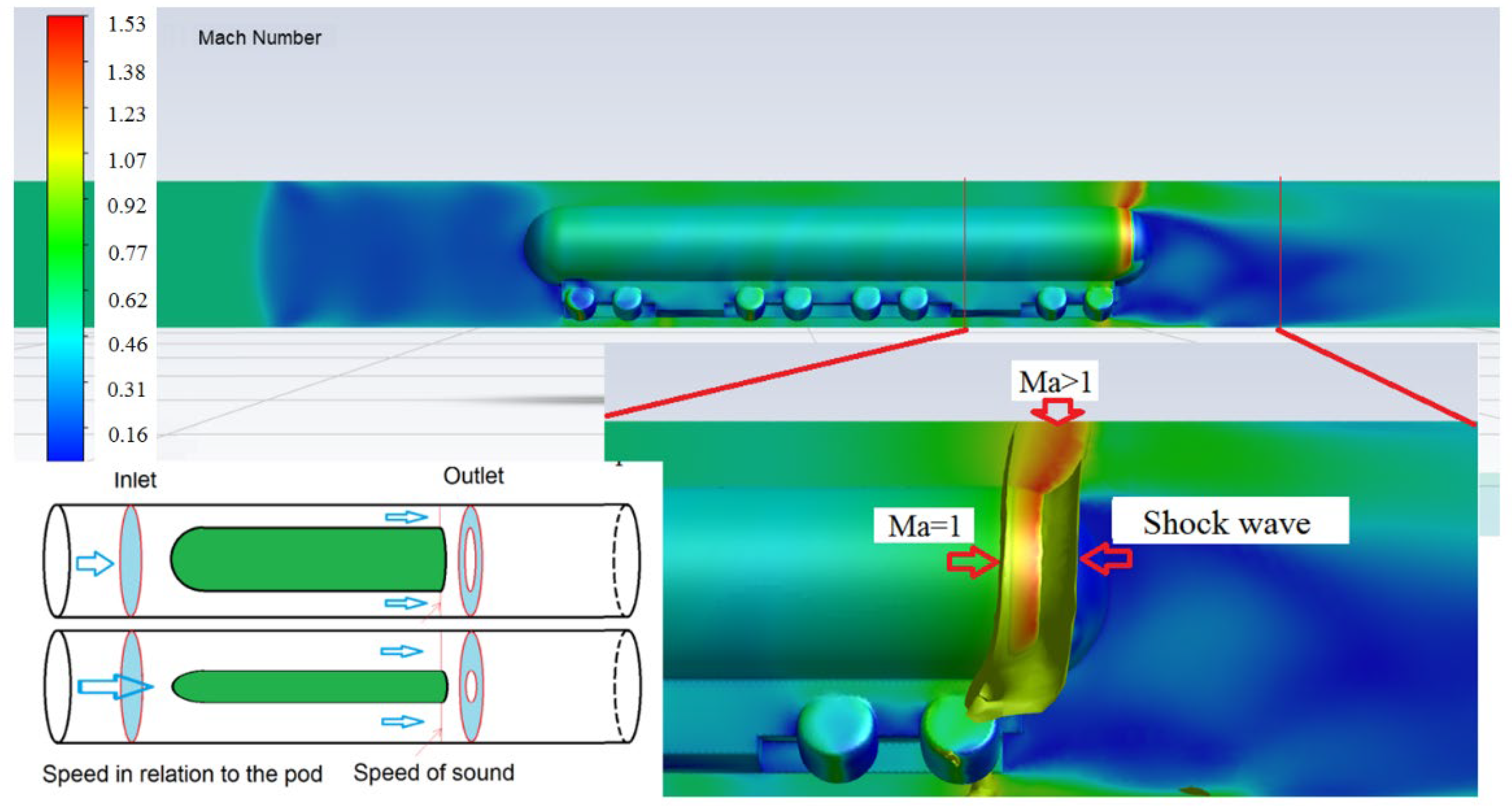
In the area around the vehicle and in the gap around it, the speed of flow is greater than the speed of the vehicle and increases with its speed, finally reaching the speed of sound. This causes the flow to be blocked at the critical flow level in the area of the smallest cross-section between the vehicle and the tunnel and a pressure surge wave appears ahead of the vehicle. The vehicle carries an increasing volume of air with it, pushing it forward. The more or less annular surface with the velocity of flow equal to the speed of sound acts as a kind of seal between the vehicle and the tunnel walls. This phenomenon is called the Kantrowitz limit [
15].
Figure 1 depicts an example of the geometry of vehicles traveling in a tunnel at a speed of 200 m/s (720 km/h), showing the complex flow structure around the rear of the vehicle when a supersonic flow area is formed there, closed by the shock wave, and constituting an invisible “gasket” restricting the flow of air around the vehicle. This, of course, increases the aerodynamic resistance of the vehicle.
Figure 1 shows the areas of supersonic flow terminating in a shock wave, arising behind the vehicle and originating from the surface where the velocity of flow equals the velocity of sound (Ma = 1).
From the equations linking the gas parameters (pressure, density, temperature, speed, free-flow cross-section), it was possible to determine the relationship between the ratio of the vehicle cross-section to the tunnel cross-sectional area and the vehicle speed at which the critical flow appears (flow velocity reaches the speed of sound) in the area between the vehicle and the walls of the tunnel (see
Figure 2).
The smaller the cross-section of the vehicle in relation to that of the tunnel, the greater the possible vehicle speed without reaching the speed of sound in the gap around the vehicle.
It is possible to further increase the speed of the vehicle, but this is associated with an increase in aerodynamic drag.
This information leads to the conclusion that, whichever way it is looked at, the cross-section of the vehicle should be kept as small as possible in relation to the cross-section of the tunnel.
In the presented solution, the diameter of the tunnel was arbitrarily set at 4.7 m to enable the transport of containers.
A basic scheme of the low pressure tube transport (LPTT) and visualization of the stations and tunnels are depicted in
Figure 3 and
Figure 4.
2.1.3. Wave Processes in the Tunnel
A vehicle running in a tunnel is like a piston running in a cylinder. Depending on the ratio of the cross-section to that of the tunnel, the piston-cylinder system is more or less tight. When the vehicle is moving fast and critical flow occurs, the piston-cylinder system is sealed.
When only one vehicle is moving, then during the acceleration phase the vehicle produces successive overlapping compression waves in front, which are transformed into a shock wave. A fan of the expansion wave is created behind the vehicle. Schematically, the propagation of these waves is shown in
Figure 5, and a CFD calculation of temporary pressure distribution in the tunnel, which is the result of a fast-moving LPTT pod, is shown in
Figure 6.
A counterpart to a vehicle moving fast and at low pressures is a rocket moving at high altitude. Under these conditions, the phenomenon of flow laminarization occurs. Due to the reduced pressure, the air density is reduced and consequently the dynamic viscosity of the air increases, which results in a reduction of the Reynolds number. The Reynolds number decreases when the pressure in the tunnel is reduced by 100 or 1000 times. The viscous effects are relatively very weak due to the occurrence of compressibility effects that generate forces many times higher than viscous forces, due to high flight speeds. The problem of turbulence model selection was studied in the publication [
20], and it turned out that the three analyzed turbulence models Spalart Allmaras, k-eps, and k-omega did not show differences in relation to the experimental results. In the case analyzed in this study, the SST k-omega model was used.
If we assume that the vehicle occupies the entire tunnel cross-section, then while accelerating with constant acceleration, the vehicle will produce a series of compression waves in front, passing into a shock wave at some distance from the vehicle. The vehicle leaves a fan of the expansion wave behind the vehicle. When the tunnel behind the vehicle is closed, the expansion waves are repeatedly reflected from the end of the tunnel and from the vehicle, causing the pressure behind the vehicle to drop significantly.
The maximum pressure build-up in front of the vehicle is:
—pressure increase,
—speed change,
—density,
—the speed of sound.
If we assume that the pressure in the tunnel is 1000 Pa, the temperature is 300 K, the air density is 0.0116 kg/m3, the speed of sound is 347 m/s, and the vehicle accelerates to a speed of 200 m/s, then the pressure increase will be 806 Pa. Therefore, the pressure in front of the vehicle will increase by 80%. Behind the vehicle, due to multiple reflections of the expansion wave from the vehicle, and from the closed end of the tunnel, the pressure will drop by more than 800 Pa.
When the vehicle reaches a steady speed, the pressure in front of the vehicle stabilizes, and the pressure behind it continues to drop. As the vehicle reduces speed while reaching the destination, the wave pattern is reversed. Expansion waves are created in front of the vehicle, and compression waves behind the vehicle converge to form a shock wave. The low pressure in the tunnel causes the amplitude of both waves to be small in absolute terms. On the other hand, relative values are very large. The amplitude of these waves depends on the speed at which the vehicle accelerates. Resistances may increase several times (3–4 times) in relation to the flow, unlimited by the tunnel walls [
21]. An interesting analysis of the aerodynamic characteristics of the hyperloop system can be found in [
22].
A more complicated wave structure occurs when there are several vehicles in a tunnel. The first vehicle has the greatest aerodynamic drag. The second and subsequent vehicles follow the trail left by their predecessor. There is less pressure in this track. Although the pressure increase generated by the next vehicle is similar, this next vehicle finds an area in the tunnel in which its predecessor was moving, and this results in lower-than-average pressure in the tunnel. Therefore, the cumulative pressure acting on the front of the vehicle is lower. The pressure waves generated by the next vehicle reach the vehicle in front and increase the pressure on its rear walls, reducing its aerodynamic resistance. The process is complex. The structure of overlapping compression and expansion waves depends on the speed of the vehicles and the distance between them.
Figure 7 shows schematically the paths of movement of four vehicles and the simplified wave systems related to them. In
Figure 8, a CFD calculation of temporary pressure distribution in the tunnel, which is the result of the two fast moving LPTT pods traveling in the vicinity of each other, is presented.
When the vehicle does not block the entire tunnel cross-section, the phenomena occurring are similar, but their amplitude is smaller.
In general, the problem of the Kantrowitz limit can be avoided by lowering the pressure in the tunnel.
A vehicle can move with a blocked flow around the vehicle between its walls and tunnel walls, but an increase in resistance requires a reduction in pressure in the tunnel. This appears to be a more effective solution than the use of compressors on board the vehicle, as was suggested in the Hyperloop Alpha report [
7].
The use of rooms with a larger volume at the ends of the tunnels, as shown in
Figure 4, reduces the amplitudes of the waves reflected from the open ends of the tunnels.
2.1.4. Operation of Vehicles as a Vacuum Pump
The analysis of the transient movement of vehicles in the low pressure rail tunnel shows that, to a greater or lesser extent, they push a certain amount of air in front of them, creating zones of increased pressure near the destination station.
This effect is stronger the higher the vehicle speed. At low pressures, any increase in pressure reduces the power consumed by the vacuum pumps. Therefore, vacuum pumps should be located near the ends of the tunnels, near the destination stations, and in front of the electric linear brakes. To enhance this effect, vehicles should be equipped with inflatable but non-contact flanges to seal the vehicle in the tunnel.
3. Low Pressure Tube Transport (LPTT) Pod Specific Requirements
In the low pressure conditions of the tunnel, it is not so much the drag coefficient of the vehicle as the frontal area of the vehicle that determines its aerodynamic drag. The smaller the vehicle in relation to the tunnel cross-section, the higher the maximum speed. This reservation can be alleviated or avoided by lowering the pressure in the LPTT tunnel.
A low ratio of the vehicle cross-section to that of the tunnel can be ensured by the use of tunnels with large diameters, or by using vehicles with small cross-sections. The first solution is very expensive, the second one limits travel comfort.
Such a limitation makes it sensible to assume that passengers will travel in a seated position and will not move freely inside the vehicle, which will enable the construction of vehicles with a small cross-section traveling at high speed, ensuring very short travel times.
The optimal solution was the principle of building vehicles with minimum permissible lateral dimensions, resulting from the dimensions of people traveling while seated.
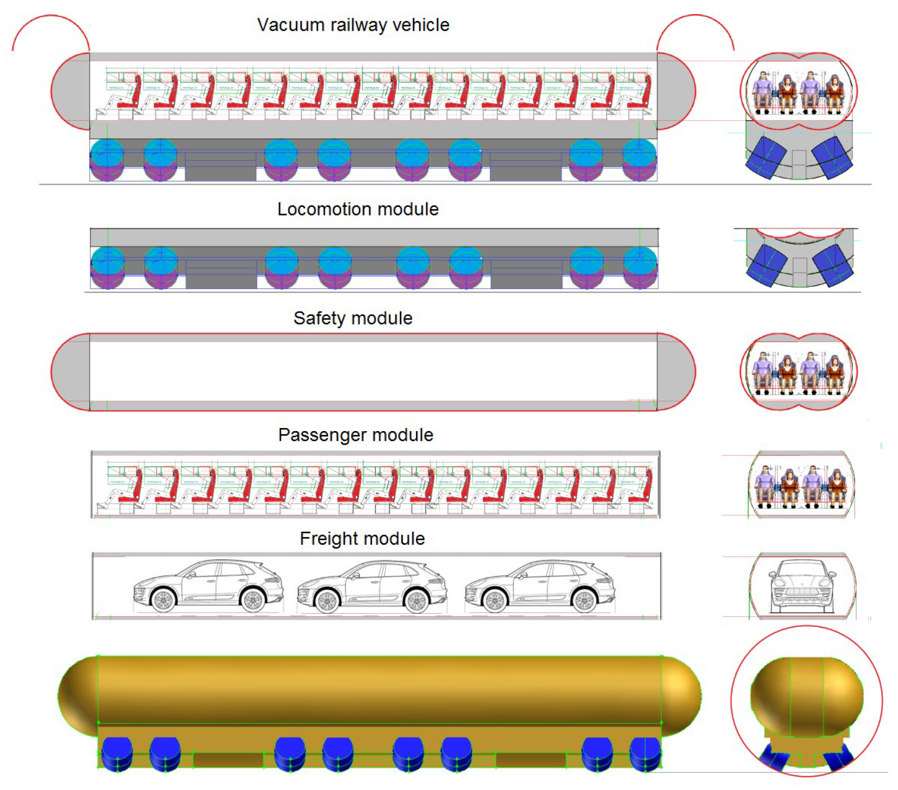
After considering the various requirements for LPTT vehicles running in long tunnels, where low pressure is maintained to dramatically reduce aerodynamic drag, and taking into account perceptions about the expectations of passengers of such vehicles and limitations of current technologies and safety considerations, it was concluded that the vehicle design should be in the form of a modular unit.
3.1. Basic Assumptions
Specific environmental conditions require specific vehicle design solutions. The overriding and absolute requirement is safety. The proposed three-segment vehicle design enables the concentration of safety efforts to one specialized segment—the safety segment. Each segment can be designed, built, and developed by independent specialized companies.
It was assumed that the vehicle must fulfill three basic functions: locomotive, safety, and comfort.
The locomotive function is understood as the ability to move along the bottom of the tunnel, accelerate quickly, and maintain a high travel speed over a long section of the tunnel.
The function of ensuring safety is the isolation of the vehicle zone occupied by passengers from the unfavorable environment in the tunnel and ensuring appropriate climatic conditions (providing an oxygen supply and the removal of carbon dioxide, moisture, and heat).
The comfort function is the provision of quick entry to and exit from a vehicle seat at the starting and ending stations and an attractive interior with virtual windows.
It was assumed that each of these functions would be provided by a structurally separate module.
In the proposed solution, the locomotive function is performed by a LPTT module based on a multi-wheeled chassis. The design of this module, with the development of technology, can change significantly, as it can be replaced with a magnetic levitation system or a system based on air cushions.
The safety module in the form of a lightweight hermetic composite tank will perform the function of ensuring safety. This module will evolve slowly, because its functions are directly related to human features which change slowly.
The comfort function is performed by the passenger module (segment), which is inserted into the safety module through one of its open ends. The module includes a seat layout, as well as side-opening covers with virtual window screens. This module may change as different technologies develop. For example, virtual windows currently based on electronic monitors may in the future be replaced by flexible visual foils or three-dimensional laser projections, causing the weight of the covers to decrease and possibly perform other functions.
Visualization of a faster 30-seater LPTT modular pod version is shown in
Figure 9 and a slower 56-seater version is shown in
Figure 10 and
Figure 11.
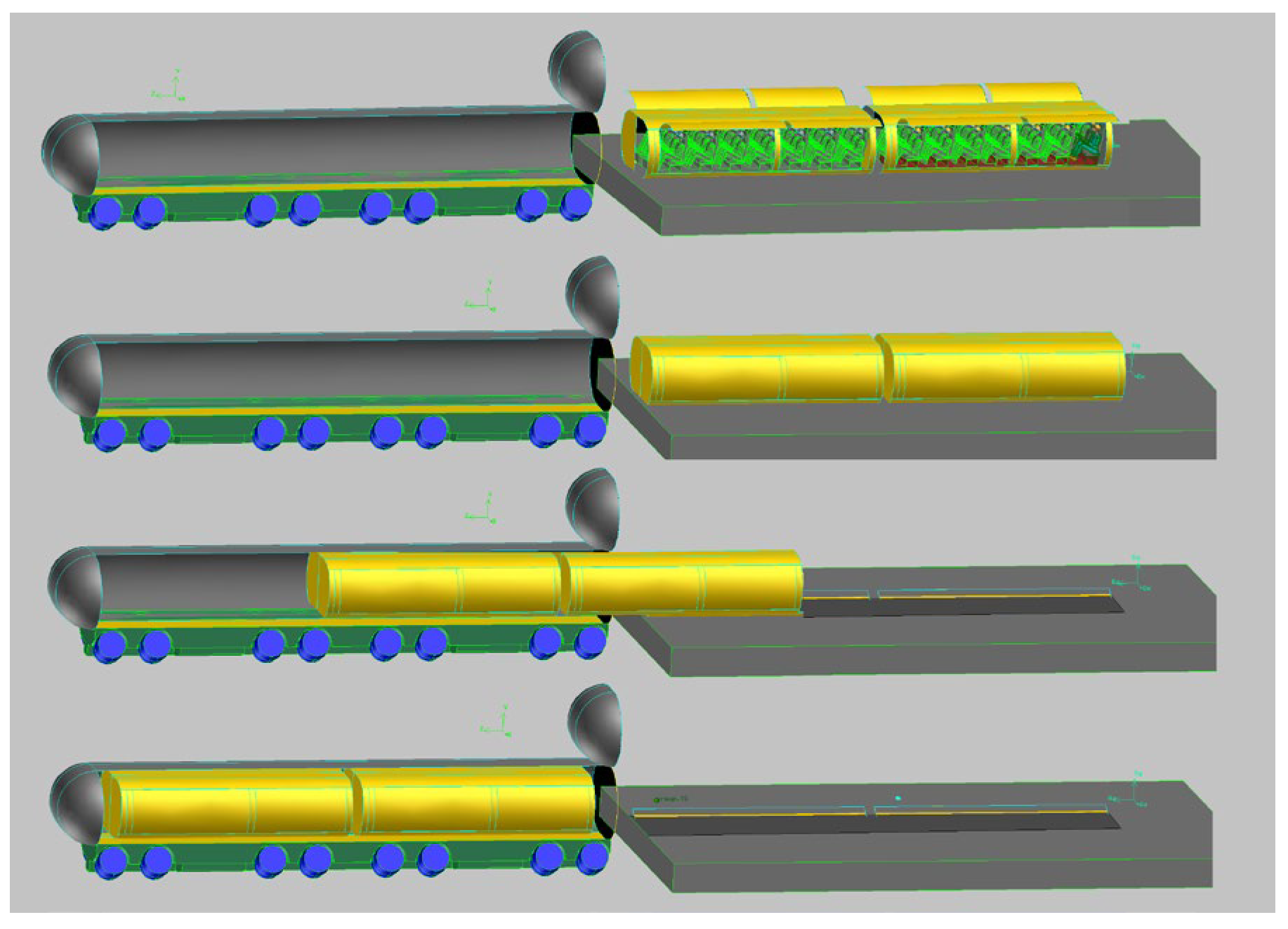
A diagram illustrating the loading of the passenger module inside the safety module, located on the locomotion module, is shown in
Figure 12. After passengers are seated in the passenger module, waiting on the platform with open side covers, the covers are closed and the module is slid into the open safety capsule. After loading, the open end of the safety module is closed and the safety capsule is encapsulated.
3.2. Consequences of Applied Assumptions
Instead of a single element pod, a three-segment modular system was proposed for the following reasons:
A pod in a tunnel can move in a traditional way on steel wheels, on rails as in a traditional railway, on flexible wheels as in the case of cars, on a passive or active magnetic cushion such as in the case of a Maglevrailway, or on an air cushion. Each solution is technically possible, but each has different running characteristics and maximum speed limits.
There is a large pressure difference between the interior of the vehicle and the air pressure in the tunnel. The conditions are similar to those of airplanes flying at high altitudes. This makes it necessary to build a structure separating the interior of the vehicle from the environment, loaded with high forces. With pressure in the tunnel of 1000 Pa and atmospheric pressure inside, a force of 90,000 N (9000 KG) per square meter of the structure’s surface is exerted. Such a high load on the structure requires a structure typical for airplanes with a small area of openings for entry and exit. This limits the speed of replacing passengers in the vehicle. The cylindrical shape of the safety module guarantees its light construction with a large and easily sealed loading surface at its ends.
A classic single-segment structure that combines the structure of a light passenger compartment with a load-bearing system of an undefined structure may be troublesome and limiting for future developments.
- 3.
The separation of the pod structure into three segments enables their parallel development and, by setting certain geometric standards, the replacement of components, built by different manufacturers and improved over time with the development of technology.
- 4.
The modular pod design facilitates the effective isolation of the safety module (safety capsule) from vibrations inevitably generated by the transport module.
- 5.
The modular design of the safety capsule with the passenger module hidden in it enables rescue operations to be undertaken using at least two methods.
One method is to use an emergency vehicle to remove the safety capsule from the transport module and move the entire capsule to the containment chamber next to the LPTT tunnel.
The second method is to use another emergency vehicle with flexible hermetic tunnels to allow all passengers to pass through to the emergency vehicle.
- 6.
In epidemiological conditions, the vehicle should ensure maximum separation from other passengers.
In the era of epidemiological threats, the passenger module with light side covers is an ideal solution that makes it possible to enter a vehicle from the platform area, where a safe social distance can be maintained, and sit directly in the seating area physically isolated from other passengers. A pod with two people side-by-side may have the seats completely separated from each other. A vehicle with four seats in a row may have a middle separation between the two seats on the left-hand side and the two seats on the right-hand side. Relatives can sit next to each other and strangers can occupy only one of the two seats. The second seat would remain empty. Results of the CFD simulations presented in
Figure 13 confirm the possibility of passenger airflow separation.
3.3. Vehicle Lifting Systems
Three vehicle lifting systems were considered: pneumatic, electromagnetic, and mechanical wheeled.
Analyses and calculations of the feasibility of a pneumatic lift system were performed. However, the conclusions of the analysis disqualified this solution for use at the present time. In the case of airbag lift, the main problem is the small surface area of the air cushion which could be realized in a vehicle moving in a circular tunnel. The solution required high cushion pressure with the associated high airflow and slots as small as a millimeter. The analysis showed that, even after using the solution described in the patent [
23] reducing the intake airflow by 5 (due to internal recirculation), there is a need to use compressors with large pressure ratios and large inlet cross-sections (at low tunnel pressures) which requires a high level of power. This is now being abandoned.
Currently, electromagnetic and magnetic systems generate too much induced resistance in relation to the lift force. This solution was also not considered in further considerations.
The focus therefore was on the mechanical wheel system.
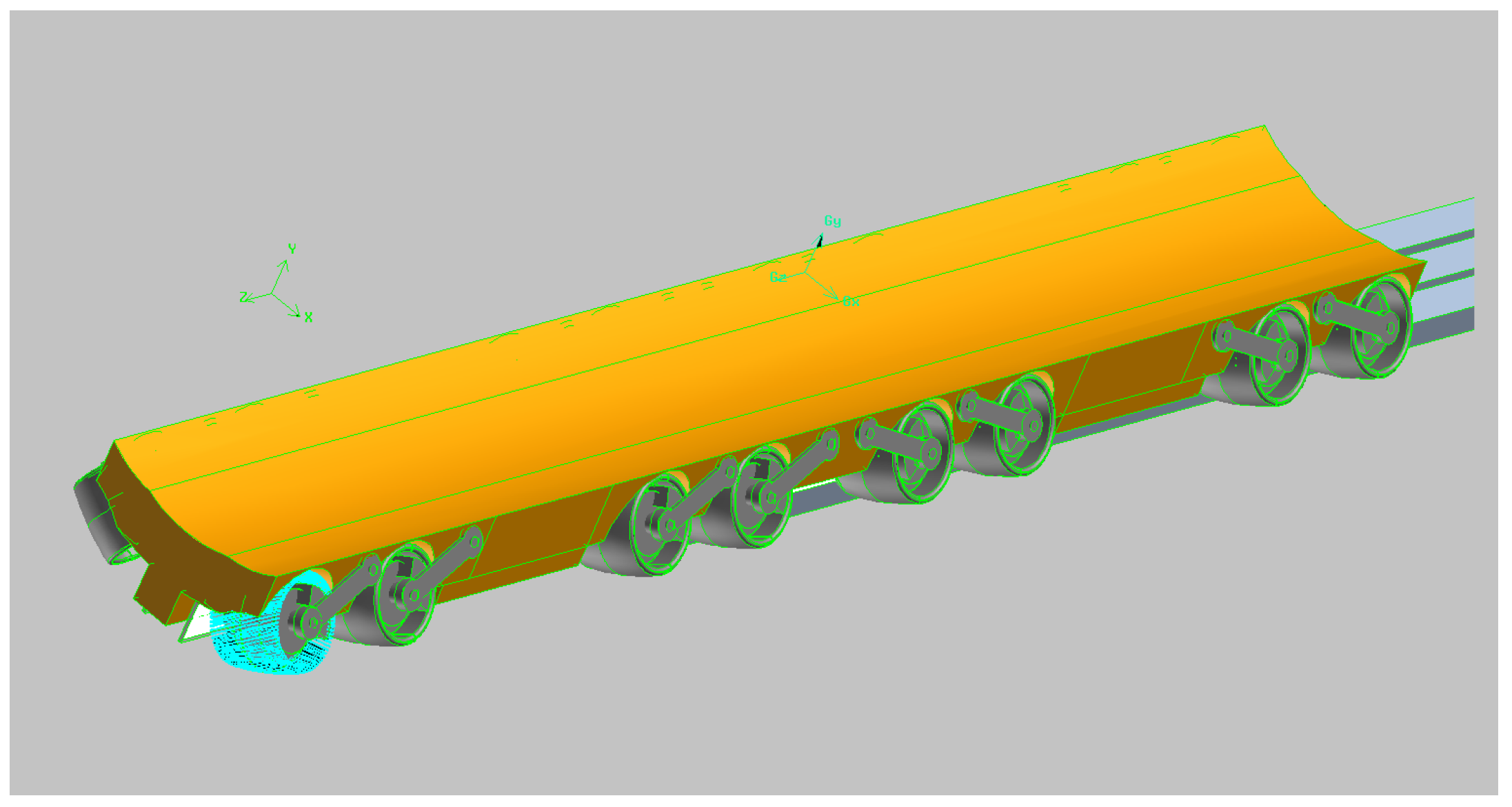
3.3.1. Multi-Wheel Vehicle Lifting System
As a tire rolls and periodically deforms, heat is generated. Under tunnel conditions (low air pressure) it is difficult to dissipate this heat into the tunnel air. Therefore, it has been assumed that the transport module will use airless steel spring tires [
24], which will be located under the safety capsule and which will be a multi-wheel structure to increase operational reliability. Such a system facilitates rescue operations by enabling emergency transport of only the safety module with the passengers.
In the case of a multi-wheel vehicle, the wheel diameters may be smaller and the load-bearing system safer (
Figure 14).
The wishbone suspension system makes it possible to lift a wheel with a damaged bearing system and continue driving with a slightly overloaded system (
Figure 15).
It has been assumed that the diagnostic system of the transport module will monitor the temperature and vibration level of the wheel bearings and, in the event of excessive vibration amplitudes, will disable the wheel from operating by lifting it.
3.3.2. Vehicle Acceleration and Braking System by Linear Motors
Regardless of the method of lifting, vehicles accelerate at the beginning of a journey and brake at the end.
It appears to be a rational idea to use linear accelerators in the form of electric linear motors at the beginning of a journey. Such an engine has a stator set in the form of groups of electromagnets switched in such a way that the active electromagnets are turned on when there is a linear motor rotor located on the accelerated vehicle in their vicinity.
A LPTT vehicle, at the beginning of its journey, should be accelerated to cruising speed as quickly as possible and decelerated as quickly as possible near the end of its journey in a tunnel.
The amount of acceleration during acceleration and during braking is mainly limited by the comfort of the passengers. It was assumed that the acceleration will not exceed the value of 0.25 g.
We can accelerate and brake vehicles by utilizing the motors, and sources of electricity on board the vehicle. This is associated with the need to transport heavy engines and energy sources.
Alternatively, we can use electric linear motors located in the tunnel walls to accelerate and brake the vehicles in the relevant tunnel zones. In the late 1940 s, Professor Eric Laithwaite of Imperial College London developed the first full-size working model of such an engine [
25]. Since then, linear motors have been used commercially in a variety of applications. The review [
26] explained the operation of various types of linear motors used in maglev systems, discussing and comparing their suitability, and described the scope of worldwide maglev developments.
The availability of permanent magnets (PM) with high energy density and the emergence of high-power electronic converters with digital controllers has accelerated the development of highly precise, energy-saving linear motion control drives.
The type of engine we are interested in corresponds to the engine proposed as a system for catapulting aircraft from an aircraft carrier [
27].
In contrast to a catapult on an aircraft carrier with similar accelerated masses (about 25,000 kg) and maximum speeds (200 m/s), the required accelerations for our system are much smaller (about 0.25 g).
In terms of efficiency, conventional rotary induction motors can achieve an efficiency greater than 90% [
28], while high-speed linear induction motors only have an efficiency of around 50% [
25].
The main advantage of a linear motor is the ability to control the acceleration of an accelerated object through feedback. Another advantage is the low maintenance required for a heavily used system. Finally, another advantage of the linear motor is the ability to work with high loads.
This would be important when accelerating trains of three pods.
In the case of electromagnetic catapults mounted on ships, the efficiency of the catapult is an important factor due to the limited power of the generators installed on ships. The low efficiency of linear motors was the reason why this project was abandoned.
In stationary applications, the low efficiency of the linear motor is not as important compared with its other advantages.
Due to the limited acceleration of vehicles during acceleration and braking, the length of the stator of some of the linear motors located on tunnel walls reaches 10 km and depends on the maximum speed to which the vehicles are accelerated.
Since the linear motors, in addition to the driving force, also generate a force transverse to the direction of movement, there is a force stabilizing the position of the movable blade of the expanded rotor, keeping the driven object in a stable position between the active stator elements attached to the tunnel walls.
Figure 15,
Figure 16,
Figure 17 and
Figure 18 show the arrangement of two uncoiled linear motor rotors installed on the vehicle and three groups of linear motor stator electromagnets situated in the tunnel.
Linear motors of this type can work as motors and as brakes. As engines, by consuming electricity, they accelerate the vehicle, giving it kinetic energy. In the final phase of the vehicle’s motion, other engines work like generators to slow down the vehicle, converting their kinetic energy into electricity.
3.3.3. Inertial Vehicle (Pod) Drive
Considering the low rolling resistance and low aerodynamic drag of the vehicle, an inertial vehicle propulsion system was considered and analyzed.
It was assumed that at the beginning of the vehicle movement, it will be accelerated by linear motor to a certain speed and will continue to move, losing the kinetic energy it gained to overcome the rolling and aerodynamic resistance.
It appears that a reasonable assumption is to allow a decrease in velocity corresponding to the loss of half of the vehicle’s kinetic energy until reaching the end station or the next linear motor. At this time, the decrease in velocity is nearly linear, meaning that the average vehicle speed is only 17% less than the initial speed. For longer routes, the additional linear engine placed in the tunnel will accelerate the vehicle until it has the expected kinetic energy to reach the station or the next linear motor.
Figure 19 shows the decrease in vehicle speed due to rolling resistance and aerodynamic drag for tunnel air pressure levels of 100 Pa and 1000 Pa, with the limits of loss of 50% of the initial vehicle kinetic energy marked. The strong effect of vehicle aerodynamic drag, proportional to air pressure, on vehicle range can be seen.
Simulations showed that, at a distance of 300 km and an air tunnel pressure equal to 500 Pa, to increase the vehicle’s lost kinetic energy to the initial level, only one additional electric linear motor located at mid-distance is needed to use the inertial propulsion system without mounting electric motors on board, except for maneuvering motors used at low speeds.
4. Tunnel Shapes
Modern technologies limit the maximum speed of movement of LPTT vehicles (700 km/h). Due to the enormous cost of building tunnels, however, they should be built in such a way that vehicles with speeds of up to 1000 km/h can move in them at a time when the level of technology allows it.
With today’s multi-wheel chassis technologies with flexible wheels, vehicles can move along the bottom of a circular tunnel. This solution is also advantageous because it does not require any additional load-bearing elements to be installed in the tunnel pipes. When other levitation systems (magnetic, pneumatic) appear, it will be possible to modify the walls of the tunnels to adapt them to the new track.
As LPTT pods generally run in a cylindrical tunnel, they have a shape adapted to this geometry. This geometry is unfavorable for movement within the station area.
Therefore, in the station area, and at atmospheric pressure, platforms (electric longitudinal conveyors) with a classic wheeled chassis running on a rail track, with an upper cylindrical surface on which the LPTT vehicles sit, are required. The pods, after leaving the airlock and anchored onto a wheeled electric platform that runs on a typical rail track, would continue moving in the classic way in the station area. A conventional track with railroad switches would be used to change the track.
5. Pod Limitations
LPTT vehicles (pods) are very specific vehicles. Their purpose and design combine the features of both aircraft and submarines.
Features of an aircraft—the pressure in the vehicle is higher than the ambient pressure, with very high speeds of movement.
Features of a submarine—total autonomy when moving through tunnels, and the need to ensure living conditions in the vehicle based on internal resources (oxygen, carbon dioxide absorption, water vapor and heat, and electricity).
And a specific feature—the need to move between the tunnel area with low air pressure and the station with atmospheric pressure.
Therefore, maintenance, replacement, and replenishment of used factors and sources of electric energy are much more complicated and time-consuming than other known means of transport.
LPTT pods move using multi-wheel suspension (
Figure 14,
Figure 15,
Figure 16,
Figure 17 and
Figure 18). The pods are relatively long, and most wheels cannot be turned. Their ability to navigate arcs is therefore limited. They can move in arcs with a very large radius, naturally accommodating its angular position in the tunnel to pod speed and arcs radius
Due to this, they require special treatment in the station area.
6. Stations
Stations are essential elements of a low pressure rail system. A detailed proposition of a station developed for Polish conditions can be found in [
18].
The idea of a station presented here was based on the assumptions presented above. With such assumptions and their consequences, the feasible structures of a station and elements of its equipment were developed to ensure continuous vehicle traffic in the tunnels at intervals of 2–5 min.
It was assumed that the stations would contain two separate areas: a low pressure area and an atmospheric pressure area connected by a series of parallel airlocks as shown in
Figure 20.
The station is the place where serial vehicle traffic in tunnels is converted into parallel vehicle traffic in the station area.
The proposed solution is the use of cross conveyors operating at minimum vehicle speeds in the station area (
Figure 21 and
Figure 22).
The construction of tunnels with turnouts making it possible to avoid the use of intermediate stations is difficult with the current state of technology.
Therefore, it was assumed that each tunnel ends at the intermediate station B and the passage from one tunnel system to the other would take place at low speed, using a system of special cross conveyors moving LPTT vehicles from one tunnel to another. A large number of shifters would be used to ensure that the transport of vehicles between the tunnels and airlocks could take place in the shortest possible time.
Overhead traveling cranes and their derivative transverse conveyors are lifting devices commonly used, so their design and modification are state of the art. The only new requirement is the need to work at low pressures.
It has been assumed that, regardless of the LPTT vehicle lifting system (wheeled, magnetic, or pneumatic), pods in the area of the station with atmospheric pressure will move on additional electric transport vehicles using typical railway tracks. After leaving the airlocks, the LPTT pods are then transported within the area of the station in classic electric vehicles with railway technology.
The main idea behind this station concept was to reduce the low pressure space and avoid the need for new technical standards, leaving the rest of the station structure at atmospheric pressure and using conventional railway technology there (
Figure 23).
LPTT pods slowed down by linear electric motors with stators mounted in the tunnel walls approach the station at low speeds. In the low pressure zone of the station, cross conveyors wait for individual pods, which will transport them in a controlled manner to an open airlock or a tunnel.
In the atmospheric pressure station area, many activities such as replacing or recharging batteries, replacing oxygen cylinders, replacing or regenerating carbon dioxide and moisture absorbers, cleaning, disinfecting, testing vehicle systems, repairing, etc., can take place in parallel even though they may be time consuming. The technical areas of railway stations are places where such maintenance activities can be performed.
Both the cross conveyors on the low pressure side and the electric longitudinal conveyors on the atmospheric pressure side can move both types of vehicles, namely, the integral single component pod (IU—integral unit) of conventional construction and the universal (UU—universal unit) three component swappable pods.
LPTT vehicles (pods) could be connected into sets of two or three pods to form a train. The weight of the whole train would increase, but the aerodynamic drag would remain at a similar level to that of a single LPTT vehicle (pod).
The security control zone can be located in front of the entrance to the station hall.
These solutions are known from airport terminals.
The construction and configuration of platforms for car transportation must be specific, as it must enable the loading of a car onto the platform.
The design and configuration of the platforms for the transport of containers must be specific, as it must enable the loading of containers onto the platforms.
Transportation of depressurized vehicles on classic tracks to other places in the city can be envisaged.
6.1. Traffic within the Station
An LPTT pod, traveling directly from station A to station C, with its own low speed wheel drive, moves from the tunnel to the cross conveyor top bed and remains anchored on it. The cross conveyor with a pod on the bed travels to the position in front of the open tunnel leading to station C. The unanchored pod, using a low speed wheel drive, enters the tunnel and approaches the linear motor with stators located in the tunnel walls. This linear motor gives it its cruising speed. The operation of moving the LPTT vehicle from one tunnel to another can be done quickly. The speed of movement of the cross conveyors with a capacity of 30 tons is about 3 m/s.
It has been proposed to use 5–6 airlocks working in alternate directions to reduce the work of the vacuum pumps between the low pressure zone and the station.
This requires the development and construction of a system enabling passage from three tunnels to six airlocks or to another three tunnels. A way to travel from one tunnel to one of the six airlocks is needed.
A compact solution was proposed (
Figure 20,
Figure 21,
Figure 22,
Figure 23 and
Figure 24). The low pressure chamber between the outlets from the LPTT tunnels and the airlocks is equipped with horizontal cross conveyors (gantries), to be positioned in the appropriate positions to receive the pod, and for its transfer to the appropriate tunnel of the LPTT or airlock.
Conveyors controlled by the computerized system move perpendicular to the axis of the tunnels and airlocks. Their speed of movement is variable, depending on the necessary distance they have to travel, and are limited by the maximum allowable acceleration (about 1 m/s2). There are several conveyors in the low pressure chamber that move as necessary to service the LPTT vehicles.
Depending on the solution, the airlock covers (doors) may be in the form of hinged cups or sliding discs.
It takes about 10–13 s for a vehicle to enter the conveyor from the tunnel or airlock. The time of vehicle exit to an airlock or tunnel is similar.
The speed of movement between the tunnels and the locks is about 3 m/s, and it changes smoothly to minimize lateral acceleration.
The covers of the airlocks are most often in the form of discs with a diameter of about 5 m, which are slid horizontally on rails placed above them to close or open the airlock, and are rotatable and can be locked into the closed position. The travel speeds are about 0.4 m/s, which make it possible to open or close the airlock in about 12–15 s.
The conveyor system makes a flexible implementation of many scenarios of the movement of LPTT vehicles possible (see
Figure 24).
The most important of them are:
Transfer from stations A to C and from stations C to A of single vehicles using one or two cross conveyors with an appropriate time shift.
Transfer from stations A to B and simultaneously from stations B to A using one or two cross conveyors.
Transfer from stations A to B and B to A, and parallel passage from stations C to B and B to C.
Forming and disassembling of a two-pod train.
Forming and disassembling a three-pod train.
After passing through the airlocks to the atmospheric pressure side, the LPTT vehicles continue to move on electric transporters along traditional railroad tracks.
The track system makes it possible to travel from any platform to any airlock, and from any airlock to any platform. This enables the flexible operation of both vehicles and airlocks in the event of disturbances in the station’s operating schedule, and saves energy used by the airlocks.
In the technical area, the basic elements of the LPTT vehicle are automatically tested, electric batteries, oxygen cylinders, containers with carbon dioxide, and moisture absorbers can all be replaced.
If a malfunction is detected, then the vehicle is removed from the technical area and replaced with a spare one.
The previously discussed scenarios of the movement of the vacuum rail vehicles between stations A and C (with the formation of a three-car set), between station B and stations A and C (the blue vehicle is a freight vehicle) and the situation of the emergency removal of a faulty cross conveyor blocking the traffic at the station, were animated and presented in the film (
Supplementary Video S1). Descriptions of each system component are shown in
Figure 20,
Figure 23, and
Figure 24.
6.2. Station Area Accessible for Passengers
Platforms are places accessible for passengers where they can load hand luggage and take their seats from both sides of the vehicle simultaneously.
Universal LPTT (UU) vehicles travel on lorries from airlocks to the front wall of the platform hall. At this time, the safety module is depressurized. Its front cover turns 180 degrees, enabling the passenger capsule to exit to the platform. The part of the station accessible to passengers is separated from the technical part of the station by a wall with openings through which passenger modules with closed side covers are inserted onto the platforms. Passenger modules roll out on rollers from inside the safety capsules onto the platforms. After stopping on the platform, the side covers are raised, enabling passengers to leave the module from both sides, taking their hand luggage with them (see
Figure 25). Up the stairs, they move to the second floor with an exit corridor and a gallery overlooking the platform hall as shown in
Figure 26.
At this time, the transport module with an open safety capsule moves to the place for servicing and the exchange of gaseous and liquid agents and electric batteries takes place.
In order to present the reader with an impression of a passenger preparing to take a seat in a small passenger segment located on the station platform, an animated visualization of the platform was attached to the paper (
Supplementary Video S3).
The platform hall is divided into individual platforms with glass walls physically separating the adjacent platforms from each other and at the same time enabling a view of the other platforms. On the second floor, there are glass windows enabling the observation of the platform hall from the second floor.
Travelers first reach the station hall where they wait to enter the platforms from which they will start their journey. On the ground floor level, they find entrances to their platforms, and when the entrance is opened, they move through the corridor through the security control zone, where their luggage will be x-rayed. After entering the platform, they take their places in the passenger module waiting for them from both sides of the vehicle, simultaneously. After all of the passengers are seated, the side covers of the module with the virtual windows are closed and the module enters the safety capsule. The safety capsule, which is part of the LPTT pod, is hermetically sealed. Then the electric longitudinal conveyor with the LPTT pod delivers it to the open airlock and enters it using its own low speed wheel drive. After lowering the pressure in the airlock and opening its cover on the low pressure side, a cross conveyor moves up to its front, which the LPTT vehicle enters using its low speed wheel drive. After the pod is anchored to the bed, the cross conveyor moves to the position in front of the appropriate open tunnel. After the LPTT pod is unanchored, it drives into the tunnel with its own drive, and moves to the linear motor accelerating the vehicle to the operational speed.
Detailed visualizations of the passenger part of the station were made for the purposes of launching a virtual simulator of a LPTT pod ride.
7. Mechanical and Virtual Simulators of the Passenger Segment of a LPTT Vehicle
To check the proposed constructions and organization, two travel simulators of this railroad were built for the presented LPTT system, a mechanical and a virtual simulator (
Figure 27). The mechanical simulator took into account the characteristic features and solutions of the passenger module. The virtual simulator additionally provided visualizations of the parts of the station available to passengers.
Tests on both simulators confirmed the assumptions underlying their construction and operation. These assumptions were the very short times of taking and leaving the seats in the vehicle and the positive feelings associated with the use of virtual windows. Sociological surveys conducted on the simulators show that a typical passenger’s opinion is that travel time over 300 km is expected to be reduced to 30–35 min.
Prior to taking their seats in both simulators, passengers were shown a video (
Supplementary Video S2) presenting basic information about the assumptions and organizational solutions of the Low Pressure Tube Transport, to prepare them for the unusual environment in the simulators.
8. Safety Aspects
8.1. Station Safety
Cross Conveyor Exchange
At present, it appears that the construction of railway turnouts that could operate at high vehicle speeds will be difficult. Therefore, it was assumed that each tunnel ends at intermediate station B, and that the transition from one tunnel system to the other will take place at low speed by means of a system of cross conveyors moving the LPTT pods from one tunnel to another.
Due to the pressure difference between the interior of the low pressure chamber and the surroundings, with a chamber width of 22 m, the ceiling part would have to be about 3 m thick if made of iron concrete.
The low pressure chamber has a technical airlock on one of the walls with internal dimensions of 7 m wide and 7 m high, with doors enabling the transportation of objects with a maximum size of 11 m on a wheelchair (airlock covers and their sliding systems) and objects with a length of 22 m (complete conveyors).
To ensure the maximum reliability of the conveyor system, and to ensure the possibility of replacing individual conveyors during system operation, the system was expanded with an additional technical crane and technical airlocks to enable the replacement of large-sized elements with workshops in the area of atmospheric pressure.
As can be seen in
Figure 28, to increase the operational reliability of the cross conveyors, there is a technical crane above the conveyors that moves along the main axis of the low pressure chamber transversely to the axis of the tunnels and the airlocks, with the load capacity and equipment of the crane trolley enabling the lifting of any empty conveyor, which can then be moved to the technical airlock. The crane also has the ability to lift a pod from one cross conveyor and locate it on another empty cross conveyor. A defective cross conveyor can be removed from the work area in minutes and replaced by another.
In this way, any conveyor can be transferred through the technical airlock to the area with atmospheric pressure for its technical inspection, repair, or replacement.
The technical crane also enables periodic replacement of the airlock cover elements on the low pressure side. Theoretically, these works could be carried out in an automated manner, without human attendance, during the normal operation of the LPTT during periods of low traffic intensity.
8.2. Emergency Station Platforms
Due to the expected dense stream of pods moving between stations, the approximate space distance between pods is about 24 km. As the tunnels leading to the station may contain several vehicles at the same time moving in the low pressure area, it is necessary to protect them from the effects of a failure of the essential elements of the station system.
In the event of blocking an inlet to the station, it is necessary at the moment of blockage to receive and unload all LPTT vehicles which stopped at the entry to the station.
The safety buffer must be located on the station access lines, but before the first railroad switches at the station (
Figure 29).
In the system of three tunnels, the side tunnels have strictly defined traffic directions. The middle tunnel must take over the role of one of the outer tunnels, therefore it must ensure two-way traffic. Therefore, it is necessary to provide for the interception and unloading of passenger vehicles in the end tunnel leading to the station or in the middle tunnel when it acts as an arriving tunnel.
It was found that, with vehicles up to 18 m long and 20 vehicles moving simultaneously in the tunnel (300 km long route), a 400 m buffer should be provided in the form of a primitive platform that could be divided into hermetic zones with a capacity of 5 vehicles.
In the event of a breakdown on the first traffic control element at the station, which in this case is a cross conveyor stuck in such a way that a LPTT vehicle cannot enter it, then the exit from this tunnel to the low pressure chamber is closed and another five vehicles stop in the first catcher segment. After the fifth vehicle has entered, the other end of this segment is closed. Depending on the frequency of the traffic, the segment will be filled with vehicles over time (5 × 2.5 min = 12.5 min or 5 × 5 min = 25 min). After separating the segment from the low pressure zone, it is filled with air to atmospheric pressure and the passengers are evacuated in the case of an emergency from the vehicles at the primitive platform. Filling successive segments and their separation makes it possible to close all of the vehicles in the isolated spaces, which are in the tunnel leading to the station at the time of failure detection, and, after increasing the pressure to atmospheric pressure, to evacuate the passengers safely.
The use of such a buffer in front of the station can ideally allow time to replace the damaged conveyor with a working one, and bring the station into operation without evacuating passengers.
In the worst-case scenario, this system will ensure that all passengers are safely evacuated at the very least.
8.3. Tunnel Safety
When potential passengers of the LPTT realize that they are traveling in a pipe with virtually no air in it, they immediately ask what happens if the vehicle is stuck in a tunnel.
When designing a LPTT system, it is necessary to consider this problem. There are many designs and system solutions for it.
In our case, we have proposed an emergency chamber with a rescue vehicle, installed every several dozen kilometers in each LPTT tunnel.
8.3.1. Emergency Braking
During the peak load of a low pressure railway, there are several vehicles in the tunnel at the same time. Immobilization of one of the vehicles in the tunnel requires an emergency stop of all following vehicles. All the kinetic energy of each of them must be accumulated or dissipated. In the event of emergency braking in a tunnel, the vehicle must be fitted with mechanical brakes.
With a steel-on-steel friction coefficient of 0.15, the maximum deceleration will be 0.15 g. Mechanical brakes dissipate energy by generating heat, but due to the very low density of the air in the tunnel, the possibilities of dissipating this heat to the air in the tunnel are very limited.
Under these conditions, the mechanical brakes require water cooling. In an emergency pressure cooling system, the resulting steam can be used to generate an additional braking force by expanding into the tunnel through forward-facing nozzles, as shown in
Figure 30. For a vehicle weighing 26 tons and a speed of 200 m/s, this energy would be 520 MJ. This requires about 400 kg of water to cool it by evaporation.
At a speed of 200 m/s (720 km/h) with 2 min intervals, the separation between the vehicles would be 24 km. On a route with a length of 300 km, there may be 12 vehicles in the tunnel at the same time. With rescue chambers spaced every 50 km then, in the worst case, two or three vehicles would stop near each of the five rescue (safety) chambers.
Motors operating as recovery systems charging a battery during braking can be also used. The Tesla 3 pack has a capacity of 75 kWh and a weight of 478 kg [
29]. To accumulate this energy during braking, two such packs with a total mass of approximately 1000 kg would be needed. Braking would last 140 s and the braking distance would be 24 km. Due to the short braking time, the energy recovery would require high generator power and a supercapacitor, rather than a battery.
8.3.2. Diagram of the Construction and Operation of Safety Chambers
In the event of a failure of the vehicle pneumatic, electromagnetic, or mechanical lifting system, the vehicle will sit down and its movement through the tunnel would be difficult.
The advantage of the proposed modular structure of the LPTT vehicle is the possibility of conducting a rescue operation in a tunnel limited to removing and transporting the safety capsules only, relatively slowly, to the nearest evacuation station.
In this situation, detaching the safety capsule from the damaged transport segment makes it possible to quickly and safely transport the capsule with an emergency vehicle to the nearest safety chamber and, after passing through the airlock, to evacuate the passengers.
It is proposed that such stations should be located every few dozen kilometers. The distance between the stations would depend on the speed of the rescue vehicle and the air supply in the safety capsule.
There are several possible reasons for the vehicle stopping inside the tunnel outside stations.
The possibility of hovering over something in the LPTT tunnel is minimized by the monitoring and cleaning systems.
Vehicles, whether inertial or electric self-driven, run on airless wheels in a multi-wheel system. Bearing damage is the greatest danger to vehicle movement. The wheels would have sensors measuring the vibration level and temperature of the wheel bearings. Monitoring the level of their vibrations would allow their replacement before it becomes hazardous.
Another safety feature is the vehicle’s multi-wheel suspension system. The multi-wheel system makes it possible to construct a suspension system that would be able to lift a damaged wheel and distribute the load onto the remaining wheels and continue driving.
The doubling of the wheel drive system should be designed so that the vehicle could move using only one of the drive units.
While developing the scheme for the construction of the LPTT vehicles, hypothetical scenarios of possible vehicle damage and stopping the vehicle in the tunnel were taken into account.
Nevertheless, it can be assumed that the vehicle may stop in the tunnel in an unforeseen manner, e.g., due to damage to the battery supplying the drive system or the failure of the control system.
In this situation, it is necessary to emergency stop all vehicles in the tunnel behind the damaged vehicle and ensure the evacuation of passengers.
It is proposed to place safety chambers every 50–60 km with emergency vehicles and airlocks, allowing the evacuation of rescued passengers.
The proposed scheme of the construction of the safety chamber is complicated, but it has the undeniable advantage of being part of the continuous structure of the running part of the tunnel. This is particularly important when efficient LPTT vehicles are driving under the rescue chamber at high speeds. The LPTT tunnel within the containment chamber is open at the top. During normal operation, this opening is covered with a two-piece lightweight but rigid cover. This cover is opened only in the event of an emergency, requiring the rescue vehicle to be lowered into a tunnel and a damaged LPTT vehicle to be pulled out of the tunnel. The lower half of the tunnel tube has a continuous structure without any local discontinuities and surface disturbances. A diagram of the structure of such a chamber is shown in
Figure 31.
In
Figure 31 and
Figure 32, a diagram of the construction of the evacuation chamber with two airlocks and an overhead crane to lower the rescue vehicle into the tunnel, opened at this point from the top to lift the damaged vehicle from the tunnel to the level of the airlocks, is presented.
In
Figure 33, a diagram is shown of one of the possible passenger evacuation scenarios.
Such a scenario of a rescue operation is possible if the vehicle’s suspension system is operational and its drive system has failed. The rescue vehicle is a tractor-type vehicle with a towing capacity that makes it possible for a damaged vehicle to be towed or pushed.
After passing through the airlock, the rescue vehicle is positioned under the crane’s hooks, lifted up and shifted to the side over the open part of the tunnel. It is then lowered into the tunnel and travels at a speed of about 100 km/h to the stopping point of the damaged vehicle. The rescue vehicle tows or pushes the damaged vehicle to the nearest available rescue chamber and positions the damaged vehicle under the crane’s attachment points. The gantry crane lifts the damaged vehicle up, moves it, and positions it in front of the airlock bolt and, after opening the airlock door, the vehicle is pushed inside the airlock. The airlock is closed. The pressure inside is raised to atmospheric pressure and passengers can leave the damaged vehicle. The chamber can eject the damaged vehicle outside, making it possible to receive more vehicles from the tunnel.
When the transport segment of the low pressure vehicle is immobilized, an attempt is made to move only the safety module with passengers onto the rescue vehicle.
Figure 34 shows a flowchart of this scenario.
The emergency evacuation of passengers is an option used in extreme situations.
Another possibility is to use an emergency vehicle to evacuate passengers through flexible and hermetic tunnels attached to the emergency exits of the safety capsule.
Pod modifications that enable passengers to evacuate to the rescue vehicle in extreme situations are presented in
Figure 35. A diagram of rescue actions in the event of damage to the chassis of a LPTT vehicle, preventing its movement and shifting the safety capsule onto the rescue vehicle, is shown in
Figure 36.
The rescue system would be based on the installation of additional circular openings in the caps of the safety capsule—emergency exits with a flange enabling automatic and hermetic connection of flexible tunnels from a rescue vehicle. Openings—emergency exits would normally be closed with discs that could be removed to the inside of the safety capsule only after atmospheric pressure had been reached on their outside. In a low pressure rail tunnel, this pressure would be achieved by hermetically connecting the flexible rescue tunnel to the rescue vehicle and filling it with air supplied from the rescue vehicle. The emergency vehicle must have a place for the evacuated passengers with a life support system and a flexible tunnel system, enabling hermetic connection to the appropriate flanges of the rescue vehicle. Passengers would be evacuated from the damaged vehicle to a rescue vehicle through these tunnels with the assistance of rescuers directing passenger movement.
The solution presented here excludes the possibility of people directly entering the tunnel. The possibility of cutting off parts of the tunnel with inflatable balloons and increasing the pressure between them was considered. However, this was assumed to be an extreme solution.
Only rescue scenarios related to the evacuation of people are presented here. Damaged vehicles can be removed at a later time.
The remaining functioning vehicles in the tunnel, using their individual emergency braking systems, can reach the nearest emergency chambers and be pulled from the tunnel to the airlocks and further to the passenger evacuation area. Special emergency vehicles would not be needed here.
The proposed scheme for the construction of safety chambers is one of many possible solutions.
From a technical, economic, and psychological point of view, a rescue operation time of 60 min would be feasible with distances between evacuation stations of 50 km.
Therefore, it should be assumed that the safety capsule, regardless of the system provided by the passenger module, must guarantee the provision of survival conditions for passengers for two hours, assuming a safety factor of two.
Safety could be increased by equipping the rescue transport crane with an air regeneration system attached to the appropriate connectors on the safety capsule.
9. Summary and Conclusions
This paper attempted to present foreseeable problems, aerodynamic and otherwise, together with their solutions to prove that low pressure tunnel transport is an interesting, competitive, and realistic alternative to road transport, due to its potentially very high vehicle speeds and significantly reduced aerodynamic drag.
The pressure level in tunnels is the main factor that reduces energy consumption for moving vehicles at very high speeds practically not possible in road transport. In such conditions, other factors determine the resistance to motion of vehicles at high speeds in tunnels. The shape of the vehicle is not the determining factor. The ratio of the frontal area of the vehicle to the cross-sectional area of the tunnel is decisive.
In the drag analysis, it is also necessary to take into account the transient processes that accompany the movement of vehicles in tunnels.
Due to the potential exceeding of the Kantrowitz limit by vehicles, it is necessary to limit its effects by reducing the air pressure in tunnels.
Specific environmental conditions require specific vehicle design solutions. The overriding and absolute requirement is safety. The proposed three-segment vehicle design enables the concentration of safety efforts to one specialized segment—the safety segment.
Because of the very significant reduction in aerodynamic drag, attention must be paid to other resistances to vehicle motion. These may be the resistances associated with lifting vehicles on a cushion of air, induced resistances in magnetic or electromagnetic lift systems, or rolling resistances in wheeled systems.
It has been shown that, currently, the least additional resistance is generated by wheeled systems.
The ability to achieve high movement speeds, and thus high kinetic energies, with low aerodynamic and rolling resistance and relatively short distances between end stations, allows consideration of a simplified but effective inertial vehicle propulsion system.
Due to the very low capacity to dissipate heat generated by the deformation of the tire elements of a wheel system, the preferred solution is to use airless tires based on metal elastic elements.
The same problem applies to mechanical braking systems requiring a liquid cooling system. One possibility for improving such systems is to use high-pressure cooling systems with evaporation of the coolant, and then use its energy to assist the braking system by jet rocket steam engines.
Practically, serial road traffic has its counterpart in the serial movement of large numbers of vehicles in tunnels.
Unfortunately, tunnel traffic requires an additional system for converting serial traffic in tunnels to parallel traffic at stations.
Low pressure tunnel traffic requires the use of airlock systems.
Road traffic requires the use of many highly skilled drivers, as opposed to fully automated tunnel traffic.
Congestion caused by various reasons in road transport should, hypothetically, also be taken into account in tunnel transport. This requires consideration in the vehicle design itself, as well as in the tunnel structure.
The transport system presented in this study is based on the use of tunnels with a circular cross-section without any tracks, which significantly reduces the cost of their construction and dimensions, and enables vehicles to attain speeds of up to 1200 km/h in the future. The location of the main centers in Poland means that the maximum distances between them do not exceed 350 km. Therefore, average vehicle speeds of around 600 km/h are sufficient to achieve a satisfactorily short journey time of 30–35 min.
The legitimate reasons for the expected disadvantages in the travel system compensated by short journey times are comparable to those for road transport over much shorter routes.
The use of airless steel spring tires improves, at low air pressure, the dissipation of the heat generated by the periodic deformation of the springs into the tunnel air.
The proposed solution of the multi-wheel airless wheel system of the locomotive device with the, at present, smallest mechanical resistance related to the implementation of the lifting function, can be developed and modified. Examples of two versions of the vehicle were considered: a fast (average speed of about 600 km/h) 30-seater for use on longer routes of 300 km with an arrangement of two seats in a row and a small front area, and a slower (average speed of about 360 km/h) 56-seater, with an arrangement of four seats in a row with a larger frontal area for shorter routes (150 km).
The proposed solution separates the need to use space technologies for the construction and operation of vehicles only to the area of tunnels, entrusting their operation within the station to facilities made with existing railway technologies.
The presented universal system of converting serial traffic of vehicles in tunnels into parallel movement in the station area based on technologies has been known for years, and is supplemented with monitoring systems and additional security. Hypothetical emergency states in vehicle traffic and the possibilities of their prevention or actions to be taken in emergency were presented. Defining possible emergency situations makes it possible to take measures to prevent them and simplify the emergency systems.
The presented design solutions are based on the current state of technology, enabling parallel and independent modifications along with future development.
The presented solutions lead to the conclusion that it is technically possible to implement a LPTT system for vehicles traveling at average speeds of 600 km/h with the current state of technology, and with a significant reduction in energy consumption compared with ground vehicles. The sociological research conducted on simulators showed that, in European conditions, people expect to reduce travel time over a distance of 300 km to 30–35 min.
The proposed and described low pressure tube transport (LPTT) system solution meets this requirement with a very high level of operational safety.
Links to visualizations on YouTube:
Ruch pojazdów na dworcu kolei niskiego ciśnienia (hyperloop)-YouTube
Zabezpieczenia kolei niskiego ciśnienia (hyperloop)-YouTube
Koncepcja dworca kolei niskiego ciśnienia (hyperloop)-YouTube


