1. Introduction
The steerability of the vehicle determines the ease and certainty with which the driver can put the vehicle on the intended trajectory and keep it on this track [
1,
2]. Increased clearance in the steering system makes it difficult to maintain the intended direction of travel. Based on the motion parameters of the car and the characteristics of the steering system, the driver anticipates the vehicle’s behavior and adjusts the angle and speed of the steering wheel rotation during turning maneuvers and while maintaining a straight-line direction of travel. The effects of the driver’s actions are the longitudinal, lateral, and inclination movement of the vehicle. The flexibility and clearance in the steering system affect the “confidence” of driving the car, and thus the steering.
Wear of the steering elements and steering linkage components causes an increase in clearance in the steering system, which makes it difficult to maintain the desired direction of travel and increases the “inaccuracy” of steering the vehicle’s direction of movement.
The element susceptible to wear and damage is the ball pin of the rocker arm. Wear is caused by friction in the joint during its rotation resulting from the vertical movement of the suspension and the turning of the wheels. Its accelerated wear may occur when driving on uneven surfaces, in an environment with high dustiness or saltiness, or as a result of damage to the seal, which protects against the ingress of dirt and water into the ball joint. Often, damage to the seal can be caused mechanically, for example by a stone impact while driving. If the rubber cover of a joint is damaged, water and debris will rapidly degrade the joint, causing loss of grease and corrosion of the metal components. Sudden damage to the rocker arm pin may also occur while driving over large unevenness. In this situation, the ball pin may even slip out of the socket and the vehicle may lose its steerability. In addition, the operating parameters such as incorrect suspension geometry and unbalanced wheels also affect accelerated wear or damage to the pin [
3,
4].
The clearance in the ball joint can cause misalignment, uneven tire wear, sometimes the pulling of the steering wheel to one side, and/or suspension noise. The permissible wear of the connector depends on the application of the vehicle. In the old literature, there is information stating that the clearance in the ball joint cannot exceed 1 mm, but today car manufacturers say that ball joints used in car suspensions should not have a noticeable clearance. The only way to check if a joint is worn is to refer to the service specifications of the vehicles and measure the clearance (both axial and sideways). Load-carrying ball joints wear out the fastest. In double-wishbone suspensions, the lower ball joint carries the load and is more prone to wear.
In suspensions where the spring is mounted on the upper control arm, the upper ball joint carries the load and is more susceptible to accelerated wear. The lower ball joint in this type of suspension is unloaded, so any clearance indicates that it should be replaced.
In the case of a MacPherson strut suspension, the strut carries the load and the lower ball joint is unloaded.
The clearance in the joint is created as a result of wear of the mating surfaces, and the spring washer causes the clearance to be canceled in the axial direction. Side clearances are not canceled. The systems used to reduce side slip of the tire [
5] in the event of clearance in the ball joint will cause instability of this system’s operation, causing the occurrence of oscillations.
During the tests, efforts were made to determine the conditions necessary to reset the clearance on the rocker arm pin, describe the impact of the clearance on the direction of vehicle movement, and assess the deterioration of the steerability.
2. Factors Influencing the Dynamic Characteristics of Car Control
The vehicle control is influenced by factors depending on the vehicle structure, including its steering system, the tires and their load, the side inclination of the vehicle, and traffic conditions: the quality of the surface and the value of the tire adhesion coefficient. They are generally defined by the concept of dynamic vehicle control characteristics. This characteristic is influenced, among other things, by:
The driver decides the value of the steering angles by turning the steering wheel. However, a vehicle’s path is also influenced by factors depending on the design and motion parameters of the vehicle and the forces transmitted between the tires and the road. As outlined above, the factors that affect the trajectory are steering wheel rotation angle, tire and suspension characteristics, vehicle stiffness and damping, steering component compliance and damping, wheel alignment geometry, mass distribution and vehicle mass moments of inertia, rolling resistance, and the conditions of grip as well as the dynamics of the turning maneuver [
6,
7,
8,
9].
The steering angles result from the angle of rotation of the steering wheels, the gear ratio and characteristics of the steering system, its flexibility and damping. They have a fundamental effect on the vehicle’s path.
The factors influencing the tire sideslip angles are related to the parameters resulting from the vehicle structure and the variables determining its motion. These factors can be grouped as follows:
All of the above-mentioned factors affect the vehicle’s trajectory. The steering angles are also affected by clearance in the steering system. The occurrence of clearance affects the direction of movement of the vehicle.
3. Assessment of the Vehicle’s Steerability
So far, no methodology for assessing vehicle steerability with analytical methods has been developed. Most often, subjective evaluations based on the opinion of the driver are used to determine the vehicle’s steerability. A number of studies and attempts to find a method for determining controllability have been carried out. In most cases, they consisted in conducting experimental tests of the vehicle movement and then the following parameters were analyzed: the vehicle path, deviation from the optimal track, or the biological response of the driver in the form of heart rate, sweating, or other parameters related to the size of the driver’s work was measured. In the described research, attempts were made to change the characteristics of the vehicle’s movement and examined the biological response, and on this basis, the conditions in which the vehicle is easier to control were distinguished. Based on the research, the influence of selected parameters on the vehicle’s steerability was determined [
16].
Hofmann et al. [
17] investigated the vehicle response time
tr to the yaw rate and the deviation from the optimal vehicle trajectory, and on this basis assessed the relationship between the track error level and the time
tr. The response time
tr is the vehicle’s yaw rate response to the control pulse.
Based on the research, the most favorable vehicle response time to
tr_opt = 0.2 s was determined (
Figure 1). This means that the vehicle is more difficult to steer with longer vehicle response times.
The response time
tr of the vehicle was considered to be an important factor in determining the steerability of the vehicle [
16,
17,
18]. It depends on cornering stiffness of tires, the weight of the vehicle, and the speed of its movement:
where:
m—vehicle weight,
V—driving velocity,
k—vehicles radius of inertia,
lf—distance of the center of gravity from the front axle,
lr—distance of the center of gravity from the rear axle,
Kf—cornering stiffness of the front axle tires, and
Kr—cornering stiffness of the rear axle tires.
Similarly, the influence of the response time on the lateral acceleration ay and the vehicle sideslip angle β was analyzed.
Weir et al. [
19], based on their own and other authors’ research, determined the ranges in which it is considered that the vehicle is characterized by good steerability, and the drivers were divided into two groups: medium-skilled and high-skilled drivers. These ranges partially overlap, and this area was considered optimal. At the end of the article was shown the vehicle response times to the steering wheel turn.
The relations presented above were used by the authors to evaluate the behavior of the vehicle with increased clearance on the rocker arm pin.
4. Assessment of the Influence of Clearance in the Suspension Arm Pin on the Vehicle Control
Driving the wheels in the correct position during the turning maneuver requires the use of a rotary connection of the rocker arm with the steering knuckle. In McPherson suspensions, the steering knuckle is connected to the control arm by means of a ball joint mounted to the control arm. The articulation wears out with use of the vehicle. The resulting clearance is manifested by the knocking of the suspension and deterioration of the driving quality. The occurrence of clearance on the rocker arm pin causes that during vehicle movement, depending on the maneuvers performed: acceleration, braking, or turning, and when driving on a road with a side slope or on a bumpy road, the clearance will be reset depending on the direction of the side force acting. A clearance of ~1 mm causes the steering angle to change by about 0.7° (which corresponds to the steering wheel turning angle by ~11°). In addition, the action of a force with changing direction generates the formation of dynamic forces acting on the pin and accelerates its degradation. In extreme cases, the ball joint may burst.
It was assumed that the clearance on the rocker arm of a size greater than 1 mm causes noise and deterioration of the steering so noticeable that it is usually removed during repair. For this reason, a 1 mm clearance was used during the tests.
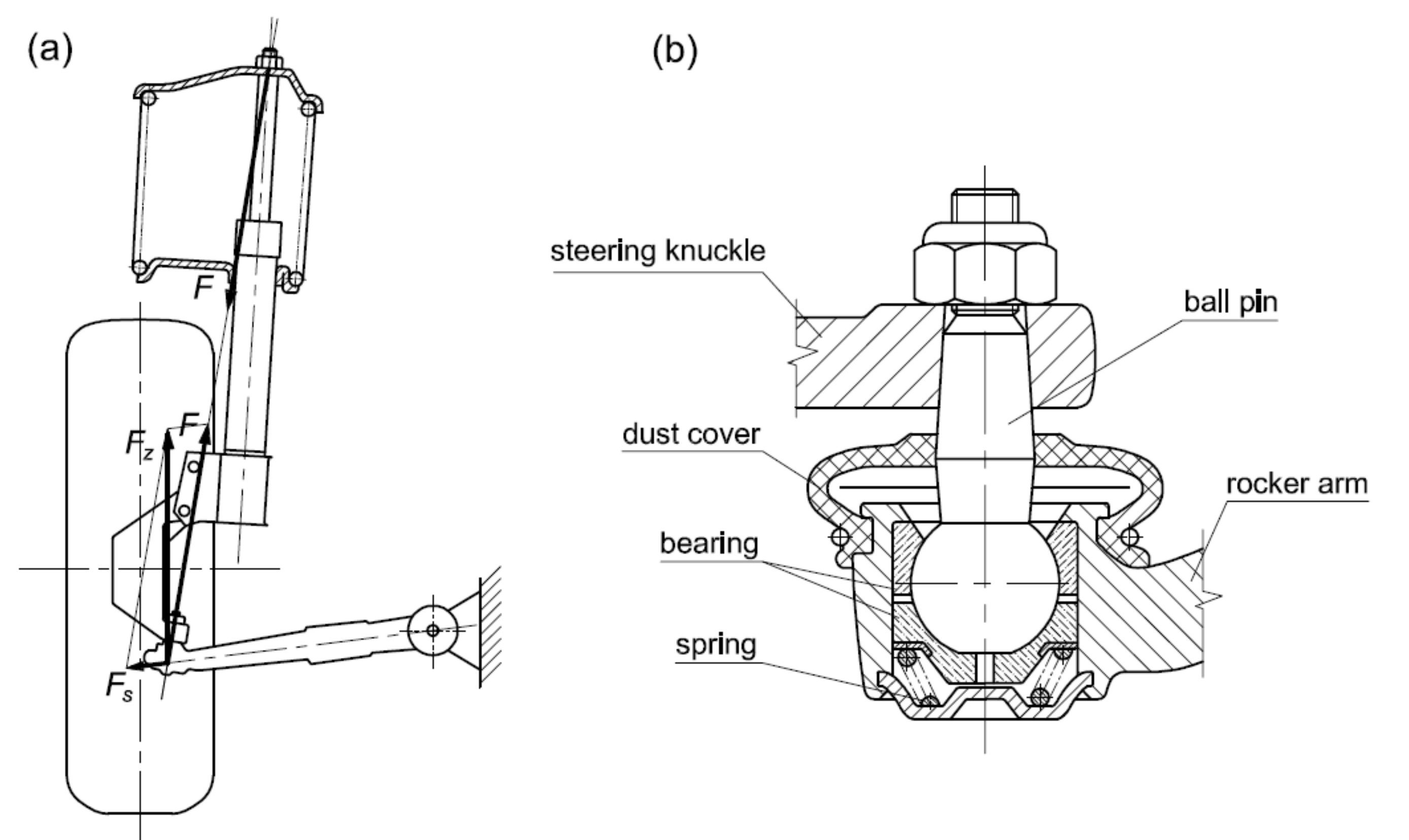
5. Analysis of the Distribution of Forces Acting on the Pin of the Suspension Rocker Type McPherson
In the case of a McPherson type suspension, the virtual axle of the steering knuckle is tilted from the vertical. The position of this axis is determined by the inclination angle
σ and the caster angle
τ of the kingpin. The loading force acting on the suspension causes the spring to deflect and the pressure force at the contact between the wheel and the road. The force component acts on the rocker arm pin and has a direction defined by a straight line passing through the steering knuckle pin and the axis of mounting the rocker arm in the body. The direction of the force is towards the outside of the vehicle. The described force causes the clearance on the pin to be reset towards the outside of the vehicle. The amount of lateral force is also influenced by the inclination angle of the rocker arm. In the case of vehicle movement on a rectilinear path, this force is counterbalanced by the tensile force of the rocker arm. During turning maneuvers or when driving on an inclined road, there is a lateral force that will cause, depending on the direction of the vehicle movement, either the clearance on the rocker arm pin to be cancelled or the rocker arm tensile force to be increased.
Figure 2 shows the distribution of forces loading the wheel.
The transverse component Fs of the force F acting on the bodywork while the vehicle is in motion causes stretching of the rocker arm (the clearance is reset to the outside of the vehicle).
While driving, the forces acting on the contact between the wheel and the road will change the direction of the resultant force acting on the pin. Deleting the clearance will change the wheel turning angle.
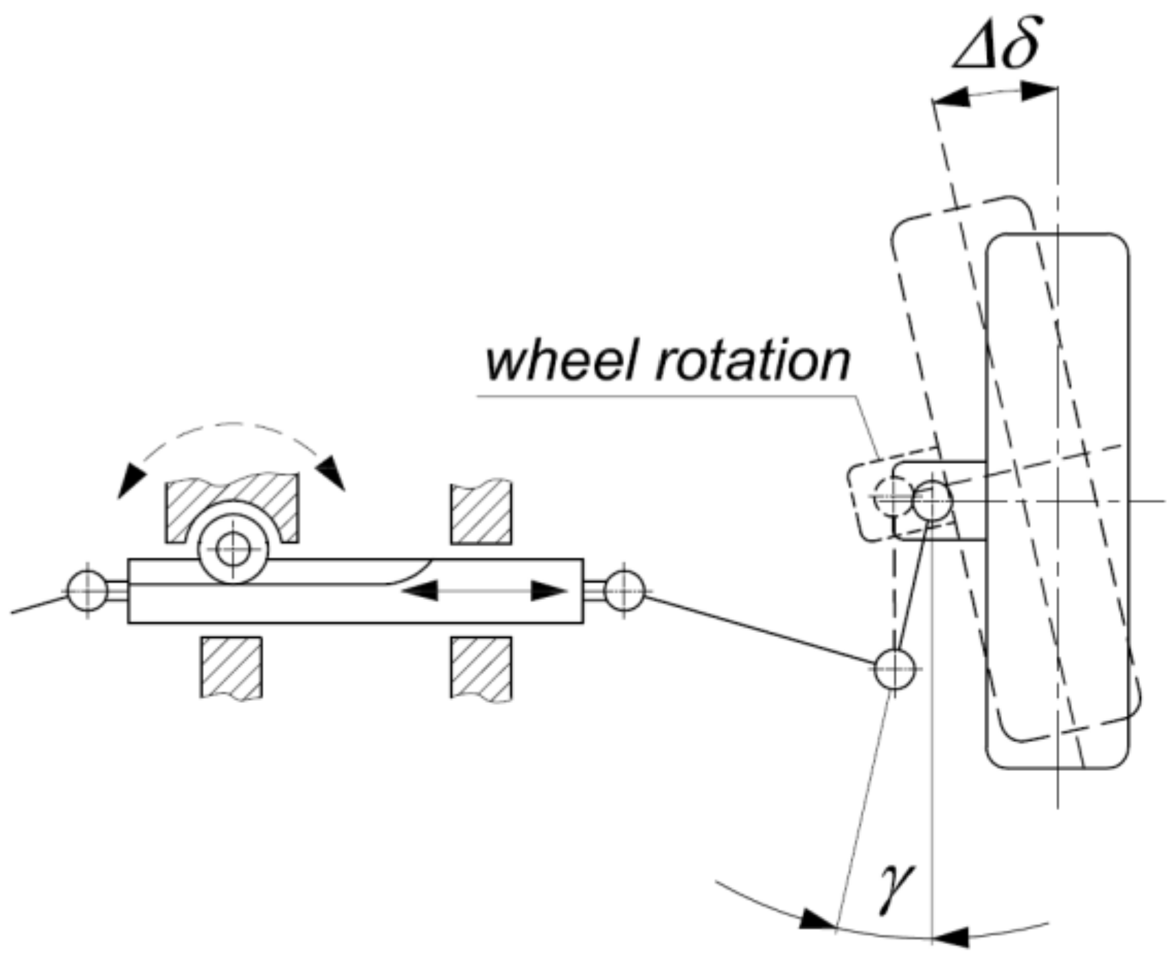
Figure 3 shows the lateral forces acting on the contact area between the wheel and the road, occurring during a turning maneuver.
Figure 4 shows the change in the steering angle caused by the clearance on the rocker arm pin.
Figure 5 shows the distribution of forces acting on the rocker arm in straight and curved motion, during vehicle acceleration and braking (for a positive wheel swing radius). The reset of the clearance of the rocker arm pin will depend on the direction of the driving or braking force as well as on the steering angle of the wheel and its direction of rotation.
6. Research on the Influence of Play on the Rocker Arm Pin on the Vehicle’s Steerability Characteristics
The research on the effect of clearance on the rocker arm pin was divided into two stages. The first was carried out under stationary conditions and the second during road tests under real load conditions.
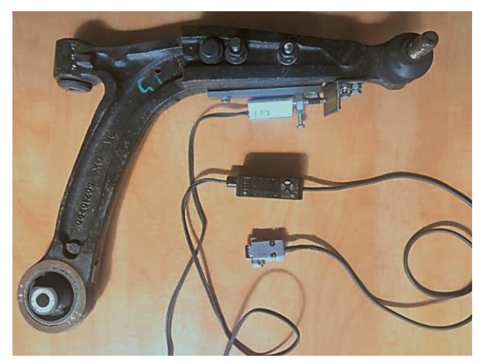
A specially prepared measuring rocker was installed in the vehicle, generating clearance, simulating the appearance of a clearance on the pin. In order to achieve a similar effect as in the case of clearance on the ball bolt, the rocker arm was cut and assembled in such a way that the part of the rocker arm with the ball joint could slide over the part of the control arm that is mounted to the car body. The parts of the rocker arm allowed for the mutual displacement of these elements by 1 mm in the lateral direction. A sensor Keyence GT is attached to the rocker arm that allows determining the moment of resetting the clearance—shown in the photo (
Figure 6).
The tests were carried out using a vehicle from the B segment (unloaded weight ~1000 kg, wheelbase ~2.3 m). The measuring arm was mounted in the right front suspension of the car.
6.1. Bench Research
The bench tests were carried out in stationary conditions. The vehicle was stationary on the platform. The load acting on the front suspension was generated by a linkage system and measured directly at the point where the forces were introduced into the suspension (
Figure 7).
The wheel was placed on a sliding base that allowed it to move freely in the transverse direction. A lateral force was exerted to the wheel. After overcoming the horizontal component of the wheel loading force, the rocker arm clearance was reset. The values of vertical and lateral forces as well as the moment at which the clearance was canceled (changes in the distance between the rocker arm mounting point and the steering knuckle pin) were measured and recorded.
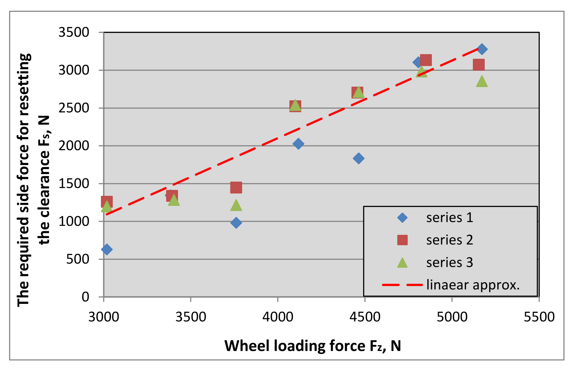
The lateral force causing the clearance to be canceled was measured for different wheel load conditions. The result of the measurements was the characteristic of erasing the clearance as a function of the wheel load. The diagram of the measuring stand is shown in
Figure 8.
Figure 8 shows the course of the lateral force acting on the contact area between the tire and the road, required to eliminate the clearance on the rocker arm pin. The obtained mileage was approximated by a straight line, and the spread of the force values obtained decreases with increasing load on the suspension.
6.2. Road Tests
The field tests were carried out with the use of the same vehicle (unloaded vehicle weight ~1000 kg, wheelbase ~2.3 m) [
20,
21]. To assess the vehicle’s steerability, three road tests modeled on ISO standards were used:
the first, during which the vehicle was moving along a circular track at a set speed [
9,
22]. During this test, the vehicle was driven under steady-state driving speed and steady steering wheel angle.
the second, during which the vehicle performed a single lane change maneuver at a set speed.
the third, during which the vehicle was suddenly braked on a flat, straight road section. The vehicle speed at the beginning of braking was ~70 km/h.
The first two tests are characterized by high lateral accelerations, both when driving on a circular track under steady traffic conditions and when changing lanes. During the third attempt, the lateral force was practically non-existent.
During the tests, speed and trajectory, longitudinal and lateral accelerations, steering wheel rotation angle, vehicle body roll and yaw angle, roll and yaw speeds, wheel speeds, brake pedal force, and pressure in wheel brake circuits were measured.
For this purpose, the vehicle was equipped with measuring devices: Correvit S-CE (Corrsys, Schwalbach, Germany) measuring head, MSW (Corrsys-Datron) measuring steering wheel, VBOX3i SL GPS measuring system with inertial module IMU04 (Racelogic, Buckingham, Great Britain), ADXL203 acceleration sensors (Analog Devices, Norwood, MA, USA) with a range of 1.7 g, MPX200 pressure sensors (Peltron, Warsaw, Poland), CL23 brake pedal force sensor (ZEPWN, Warsaw, Poland), incremental encoders with a resolution of 1024 pulses/rev (HEEDS, China), and CRS03 gyro sensors (Silicon Sensing Systems Japan, Hyogo, Japan). Measurement data was recorded with a frequency of 100 Hz in the AD-32 (Grapol Electronic, Warsaw, Poland) [
15,
20,
23] and VBOX Racelogic [
24] measurement systems.
6.3. Measurements and Evaluation of Vehicle Steerability
On the basis of road tests, the described parameters characterizing the vehicle movement were determined. The results for the ride on the circular track, single lane change, and braking tests on a straight road section are presented below. The tests were carried out for the following vehicle: roadworthy (the possibility of a clearance in the rocker arm pin is blocked) and with a testing rocker that simulates a clearance on the pin. The measuring rocker arm is mounted in the front right wheel suspension.
6.4. The Ride on the Circular Track Test
During the test, the vehicle was moving along a track with a certain radius at a set speed.
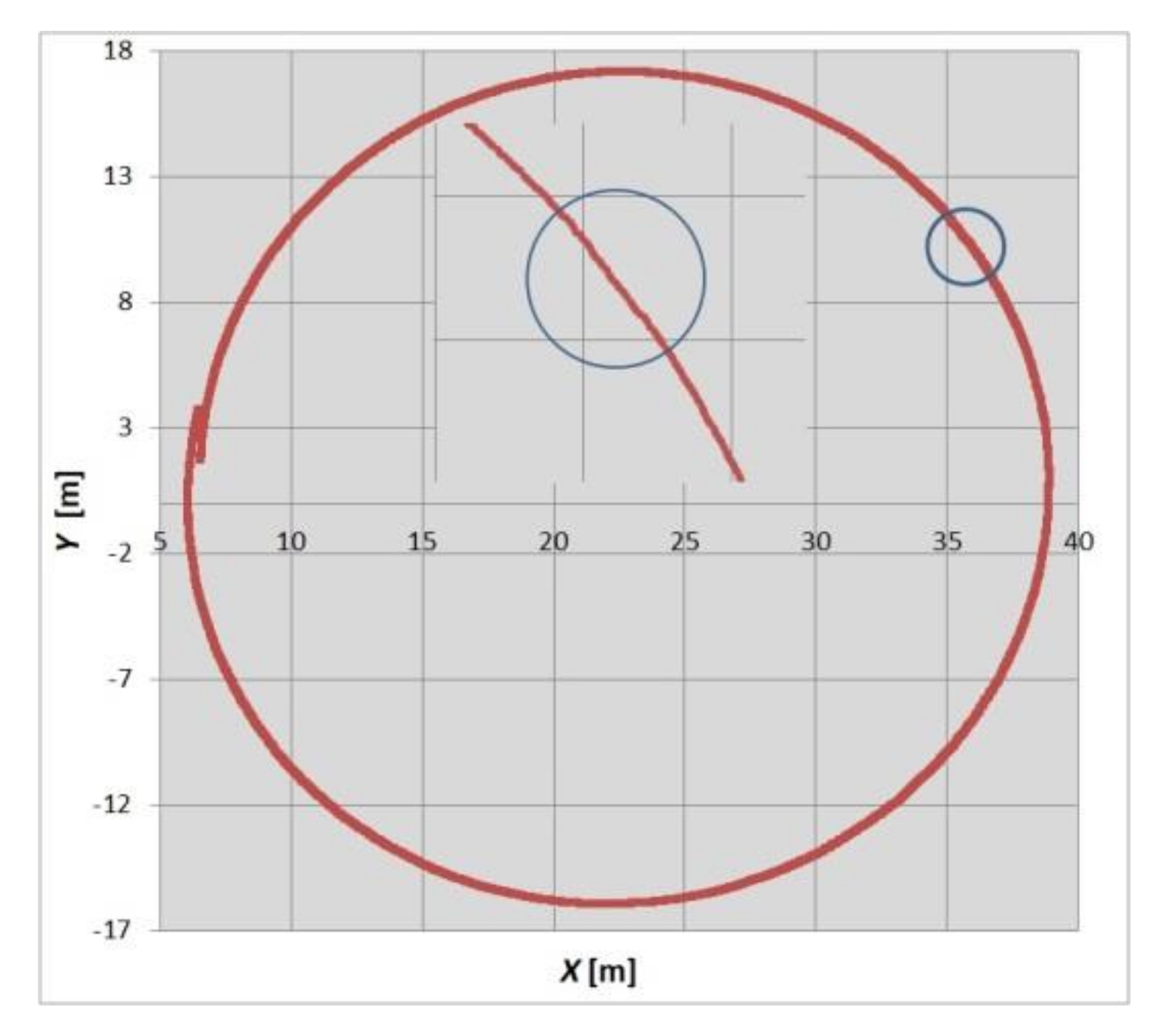
Due to the fact that the vehicle was driven by the driver, efforts were made to approximate the traffic parameters assumed for the test. Attempts were made to keep the driving speed the same for both tests (roadworthy vehicle and with clearance in the rocker arm pin). The diagram below (
Figure 9) shows the vehicle trajectory with a noticeable change in the trajectory resulting from the erasure of the rocker arm clearance, obtained from the GPS satellites of the VBOX system.
When driving on a circular track, the angle of rotation of the steering wheel is practically unchanged. Despite the very small difference in the angle of rotation of the steering wheel, there are slight differences in the values of the yaw angle and lateral acceleration.
6.5. Single Lane Change
During the test, the vehicle performed a lane change maneuver at a set driving speed. Due to the fact that the vehicle was driven by the driver, efforts were made to approximate the traffic parameters assumed for the test. Attempts were made to keep the driving speed the same for both tests (roadworthy vehicle and simulated slack).
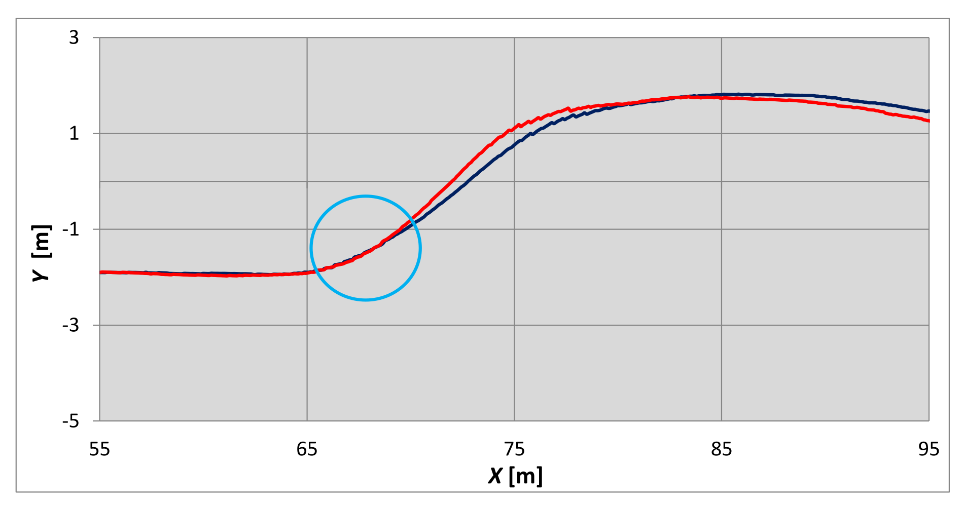
Figure 10 shows the vehicle trajectory with a noticeable change in the trajectory resulting from the erasure of the rocker arm clearance. This trajectory was obtained from the VBOX system.
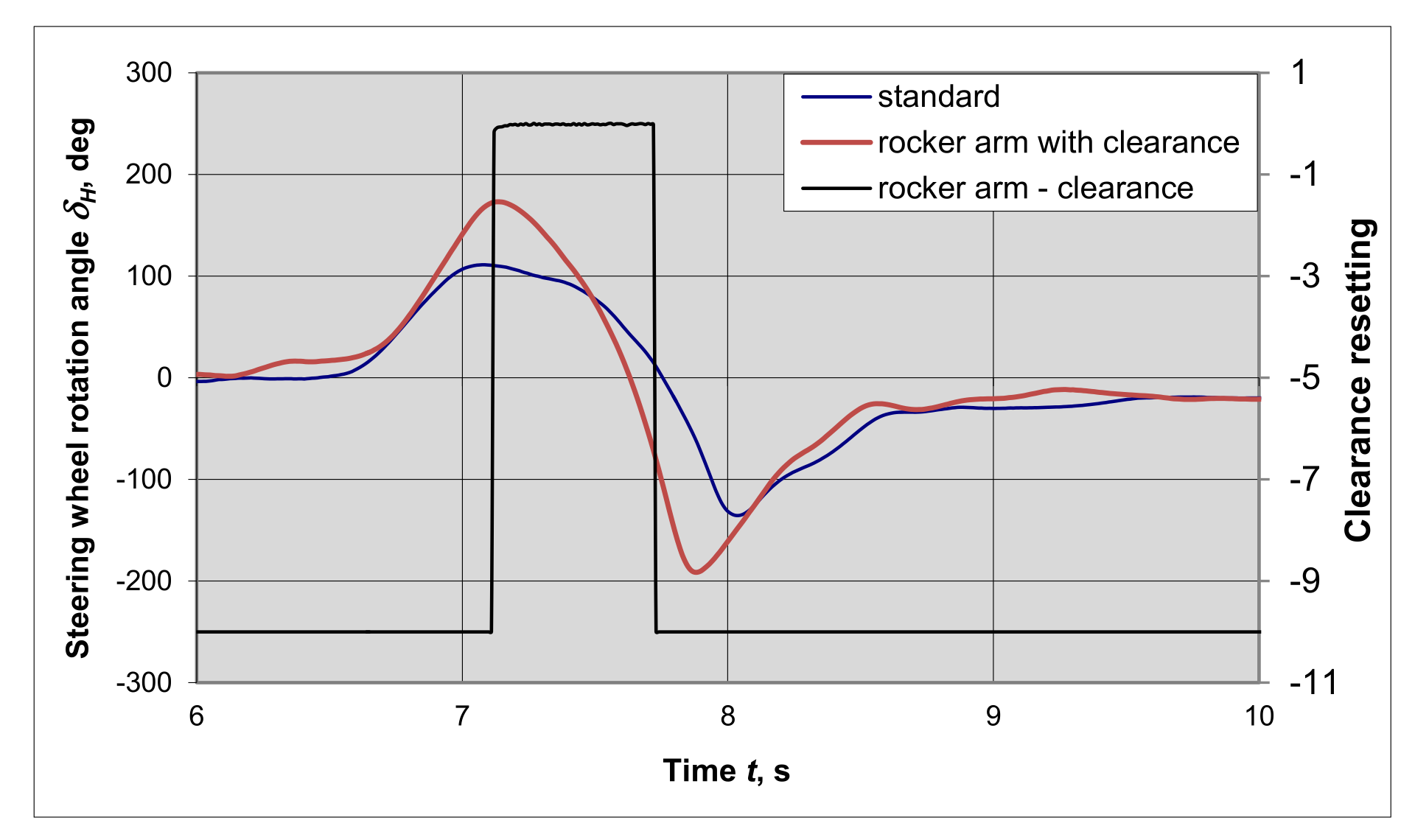
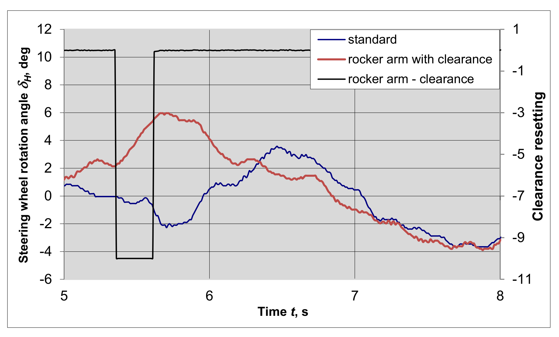
Figure 11 shows the angle of rotation of the steering wheel during a lane change maneuver at a travel speed of 40 km/h.
Figure 11 shows the moment of resetting the rocker arm pin clearance. The blue line shows the steering wheel rotation angle of a roadworthy vehicle, and the red line shows the vehicle with the increased clearance of the rocker arm pin. Although the angles of the steering wheel rotation clearly differ, the course of the vehicle motion path is very similar, and the yaw velocity and lateral acceleration values are similar. At lower speeds, the clearance effect was less noticeable.
6.6. Braking on a Straight Road Section
During the test, the vehicle was braking from the initial speed of ~70 km/h.
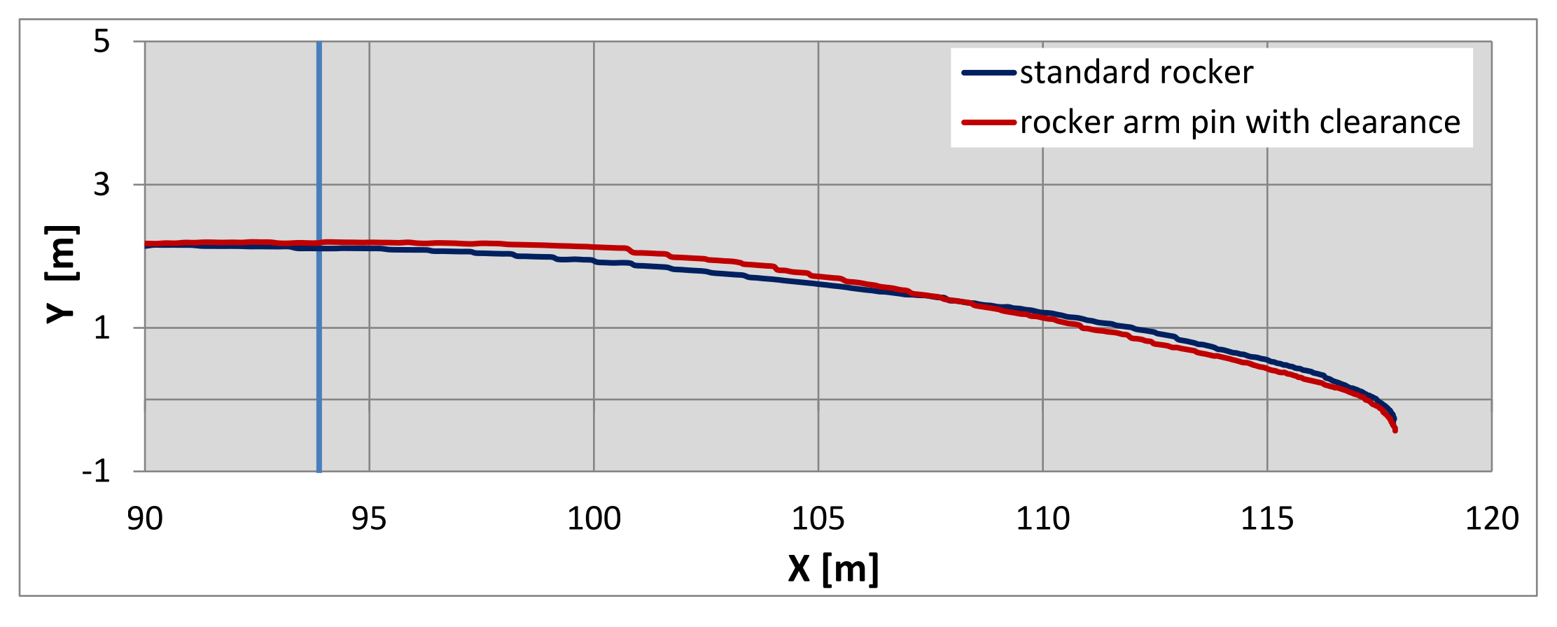
Due to the slight curvature of the track (
Figure 12), the vehicle slightly turns to the right in both cases of braking. The beginning of braking is marked with the blue line. The clearance was cancelled at the moment of the change from vehicle acceleration to its braking.
Figure 13 shows the steering wheel rotation angle during the braking maneuver. In the initial phase of braking, with a slight movement of the steering wheel, the clearance of the rocker arm is reset. Increasing the braking intensity changes the direction of the lateral forces on the wheel, and the clearance is canceled in the opposite direction.
Lateral acceleration in a roadworthy vehicle with increased clearance in the rocker arm pin is slight and may result from the operation of the ABS system.
The conducted tests were used to determine the influence of the rocker arm pin clearance on the vehicle’s steerability.
7. Influence of Rocker Arm Pin Clearance on Vehicle Steerability
Due to the oblique position of the steering knuckle, the clearance cancellation takes place after the lateral force component required for the clearance cancelled is achieved. The king-pin inclination angle and the instantaneous wheel load affect the amount of force necessary to eliminate the clearance. Additionally, the fact of accelerating or braking the wheel in the suspension with clearance in rocker arm pin will also influence its size.
Based on the analysis of measurement data, it can be concluded that the easiest way to reset the clearance is as a result of changing the direction of the steering wheel rotation.
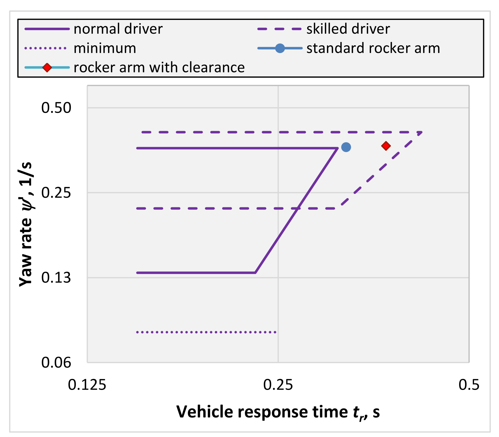
On the basis of the research, attempts were made to determine the influence of the rocker arm pin clearance on the vehicle’s steerability. For this purpose, the above-described relationships and charts were used. The results of a single lane change maneuver test were used to present changes in vehicle steerability. The comparison shows that the vehicle response time to the yaw rate in the case of a roadworthy vehicle is 0.32 s and in the case of vehicles with a clearance in the rocker arm pin is 0.37 s.
Figure 14 shows the response time of a roadworthy vehicle, during a lane change, marked with a blue point, and a vehicle with a clearance on the rocker arm pin marked with a red point.
When assessing the vehicle’s handling, it can be concluded that both measured values of the vehicle response time are within the acceptable range, while for a vehicle that is in good working order, the response time is shorter, close to the value recommended for a driver with average skills. The response time of a vehicle equipped with a rocker arm simulating the clearance on the rocker arm pin is greater and lies in the field where a skilled driver will find the vehicle steerable, while for a medium-skilled driver, driving such a vehicle may be difficult.
The clearance in the control arm joint causes the vehicle’s response time to the movement of the steering wheel to be extended, which clearly indicates a deterioration of the vehicle’s maneuverability.
Relating the values of the vehicle response time to Equation (1), it can be assumed that the clearance in the rocker arm joint causes an effect similar to the reduction of the tire’s cornering stiffness. In such a case, we can propose a modification of the equation to the form:
The coefficient was introduced in the equation, changing the cornering stiffness of the front tires α < 1. The size of the coefficient will depend on the amount of clearance. Based on the research, the value of the coefficient α ≅ 0.7 was established.
The presented analyses show that the increased clearance of the rocker arm pin is particularly visible when analyzing the direction of vehicle movement. If the steering wheel rotation angle is kept constant, it causes a change of the direction of travel at the moments of overcoming road unevenness, and in the case of turning maneuvers, when changing the direction of the steering wheel rotation, it will cause the necessity to increase this angle by the amount resulting from the clearance.
8. Conclusions
The effect of the increased rocker arm clearance on the vehicle steerability is presented above. The control arm with the introduced clearance was mounted in the suspension of the front right wheel. In the tests that were carried out, the wheel was an outer wheel, i.e., a weighted wheel.
Based on the dimensional analysis, it was found that the 1 mm clearance causes the wheel steering angle δw to change by about 0.7°, which corresponded to a change of the steering wheel rotation angle δH by ~11° in the tested car. Increasing the clearance value of the rocker arm pin in will increase the value of this angle.
The tests were carried out in stationary conditions on a test stand and during road tests of the car. The bench tests made it possible to determine the required lateral force causing the clearance to be canceled depending on the wheel load (characteristics of erasing the clearance). This characteristic is approximately linear, the amount of force required to eliminate the clearance increases with the load on the wheel. The minimum value of the force required to remove the clearance results from the kingpin inclination angle and the wheel suspension load.
The road tests were carried out in the conditions of vehicle motion characterized by high values of lateral acceleration and during the braking process on a rectilinear section of the road. On the basis of road tests, it was established that obtaining the required lateral force to eliminate the clearance occurs relatively quickly when the direction of travel is changed as a result of changing the steering angle of the steered wheels and when the direction of the drive transmission is changed (acceleration-braking).
The increased clearance of the rocker arm pin, in the case of a lateral force sufficient to eliminate the clearance, causes the change of the steering angle of the wheel, regardless of the angle of rotation of the steering wheel. In most cases, resetting the clearance occurs at the initial moment of turning the steering wheel, but it can also occur when the road is sloping, negotiating bumps or driving on surfaces with different coefficients of traction under the wheels of different sides of the vehicle.
The analyses show that the increased clearance of the rocker arm pin, as a rule, causes a change in the direction of the vehicle movement during various maneuvers. This causes the feeling of “uncertainty” in steering the vehicle and increasing the vehicle’s response time to maneuvers. The analyses show that the steering uncertainty is not strongly felt by the driver, yet it requires the driver to correct the steering wheel angle. There was no significant influence of the rocker arm play on the vehicle stability. However, increasing the clearance may make the steering uncertainty more perceptible.
The measure of vehicle steerability, which appears in most of the works, is the vehicle’s response time to the movement of the steering wheel. The lateral acceleration ay and the yaw velocity are taken into account for the analysis. Using this method of assessing the vehicle steerability, the influence of clearance in the control arm joint on the vehicle steerability was presented. After introducing a clearance of ~1 mm, the vehicle response time increased by ~20%.
Based on the research, it was found that, for a driver with medium skills, the increased clearance of the rocker arm (1 mm) will cause difficulties with steering the vehicle, especially during sudden steering maneuvers.
The presented analysis shows that the increased clearance of the rocker arm pin affects the vehicle’s steerability and extends the vehicle’s response time to steering maneuvers, and this affects road safety.


