1. Introduction
The integration of alternative generation sources at the power grid’s distribution level has led to new challenges in the control, communication, and management areas of the electrical network. Indeed, availing local resources comes with added complexity and requires coordination mechanisms to ensure their effective integration, leading to the organization of local electrical agents into microgrids. A microgrid is a cluster of
distributed generation units (DGU) with power management and regulation capabilities that cover a local power demand [
1,
2]. Microgrids add flexibility since their operation is not restricted to a permanent connection to the main power grid; they can act independently in what is known as
island operation. However, switching between operating modes implies varying dynamics and dealing with a “weaker” network whenever the main power grid is disconnected.
A microgrid interacts with the main grid through a single
point of common coupling (PCC). Disconnection events can be intentional, e.g., in the case of maintenance routines, or unintentional, caused by faults or disruptive events [
3]. An unintentional disconnection would force an island operating state, potentially introducing harmful transients and degrading power quality. It is then essential to detect the islanding events within the microgrid to trigger ancillary services and exert compensating actions [
4]. However, DGUs are
distributed and the microgrid is expected to integrate DGUs and other electrical agents in a
plug-and-play fashion. A changing, variable, and spread microgrid poses severe challenges to a typical communications approach. Therefore, there is a need for distributed
island detection algorithms.
Detection algorithms can be classified as (i)
remote detection methods (RDM), (ii)
passive detection methods (PDM), and (iii)
active detection methods (ADM) [
5]. RDMs are typically based on supervisory control techniques, relying on communication infrastructure. Then, some of their main disadvantages are communication latency and interference in power-line-based methods [
6]. PDMs monitor electrical variables, e.g., at the PCC [
5], to create a tripping signal according to predefined thresholds [
7]. As the signal must be shared across the microgrid, PDMs typically imply the need and disadvantages of communication infrastructure. Finally, ADMs operate at individual DGUs introducing minor electrical disturbances to the grid, analyzing the response, and determining its operational state [
8]. The main drawback is the degradation of power quality due to the introduced electrical disturbances and the late response depending on the electric disturbance. Also, multiple interacting DGUs may interfere with each other [
9].
PDMs and ADMs are
local detection techniques [
10] due to the continuous monitoring and analysis of “local” electrical variables such as voltage, frequency, and active and reactive power. In PDMs, the electrical variables are constantly evaluated against an established threshold; namely, rate of change of voltage (ROCOV), rate of change of frequency (ROCOF), over/under voltage, over/under frequency, active power mismatch, and reactive power mismatch [
10]. As expected, PDM techniques’ performance rely on the type of acquired measurements and their location, sometimes needing additional systems to verify or broadcast the detection signal as discussed next.
For instance, Abd-Elkader et al. [
11] proposed a ROCOV PDM based on detecting voltage drifts surpassing a predefined threshold. For large active power mismatches, this algorithm detects the island event 200 ms after the disconnection. However, small variations require the validation of a secondary strategy, implementing a physical load disconnection to raise the variation, adding 84 ms to the detection time. Similarly, Gupta et al. presented a ROCOF PDM [
12] that uses the difference between the generated and demanded active power, the rating of the generation units, and the fundamental frequency to find the ROCOF over a defined time window. The detection time depends on such window as the ROCOF is compared to a predefined threshold value until the sample window is closed. The algorithm also introduces small frequency deviations through the
q-axis control of a grid-side converter. Since such disturbance can cause small periodic deviations in a “weaker” grid, they can be used as trigger signals. In the end, it detects the island condition between 100 ms and 200 ms. However, the presence of externally introduced frequency drifts can cause false detection signals and a communication infrastructure is needed to gather the actual power demand.
To minimize these shortcomings,
hybrid detection methods (HDM) were proposed, commonly classified as series or parallel. Series methods comprise two detection layers: a PDM or an ADM, and a high-level monitoring-based strategy. Only when the monitoring layer detects an islanding event, the PDM or ADM is activated to verify, limiting the ADM disturbances as they are only needed if the first condition is met, and minimizing false tripping. However, the detection time increases if a window-based technique is used at the second layer. A parallel configuration comprises both detection layers running concurrently, generating a tripping signal if both “agree” on a disconnection event. However, this configuration combines the weaknesses of the selected methods [
9,
10]. Indeed, the detection systems are improved by combining different strategies, but some of the advantages can be lost as well.
For example, the work presented in [
9] proposes combining a PDM and an ADM in a series configuration. The ADM was placed at the second layer to minimize its polluting actions and avoid false tripping. The PDM strategy monitors the ROCOV and the rate of change of the voltage harmonic content at the PCC. A voltage index is then calculated as the negative and positive sequences ratio of the delivered voltage. Subsequently, by comparing the obtained voltage index to a previous voltage index value, a percentage delta can be computed. The total harmonic distortion index is then calculated by obtaining the percentile difference of the harmonic content in one fundamental signal’s period. Then, the differences can be compared to specific thresholds, however, the authors do not provide further information on how the threshold values are obtained. Overall, the proposed method is capable of detecting the island event in 138 ms with minimum disadvantages, such as the injection of polluting action of the ADM.
Pouryekta et al. [
5] presented a series RDM-PDM. Their objective was to minimize the
nondetection zones (NDZ) and hasten the detection signal. The chosen RDM detected signals injected to the power-line and the PDM was ROCOV-based. It monitored the voltage phase angle during a defined time window, and yielded a detection time of 200 ms. Nonetheless, the method relies on communication infrastructure, hindering its decentralized applicability. Finally, Bakhshi-Jafarabadi & Popov [
13] introduced an HDM based on a series PDM-ADM. The PDM is based on the ROCOV at the PCC. If a defined threshold is surpassed, the ADM verifies by distorting the reference current
d-axis. Then, the active power is analyzed for any variation that would indicate an island operation. The entire process takes about 300 ms in large power mismatch scenarios; for smaller variations, the delay might be higher or the event could be missed.
Despite the advantages of HDMs, they pose future operational challenges in fully distributed microgrids. All hybrid methods include at least one detection layer bound to critical data, only available through a communication network. Therefore, methods operating in a “local” fashion such as ADM are required. Nonetheless, the polluting nature of these strategies can also have a negative effect as previously discussed. In any case, there is a need for distributed island detection methods that do not compromise the quality of the delivered energy.
Overall, DGUs are expected to operate independently within a microgrid under a distributed approach. Their management is desired to be decentralized, not relying on a communication layer or a central controller. Therefore, a passive detection algorithm is proposed in this work, operating over local DGU variables only. Specifically, the proposed algorithm analyzes the power-frequency ratio deviations at the DGU terminals without inserting disturbances to the grid. Opposed to the reviewed literature, this algorithm does not require a communication network or a secondary verifying system, interacting directly with its associated DGU and acquiring measurements directly from the DGU’s outputs. Out of this, the proposal does not imply adding devices but adding a software module to the DGU controller, avoiding increased costs or maintenance.
Such a distributed approach eradicates the need for communicating a tripping signal, as each generating unit would make the same detection independently. In doing so, the cost of new communication lines can be saved, and plug-and-play features can be availed in future microgrid implementations. In addition, since the proposed method does not inject any electrical disturbance to the grid, it is possible to have multiple DGUs operating under the same island detection mechanism without major concerns regarding the interference between each other.
The proposed method was tested in simulated scenarios and experimentally through the hardware-in-the-loop approach. It exhibited a maximum detection time of 40 ms on a multi-inverter configuration, and of 25 ms for a single DGU system. Also, the proposed method was able to avoid false tripping in relevant test cases, resulting in a safe and reliable approach.
The remaining of this work is organized as follows.
Section 2 discusses the different test-beds proposed across the literature to validate island detection techniques. Out of this, one test-bed is selected for testing the current proposal.
Section 3 introduces the proposed detection algorithm, highlighting its operating principles. Then,
Section 4 introduces a validation protocol based on the selected test-bed and the test-cases found in the literature.
Section 5 and
Section 6 show the simulation and experimental results of this work, in more detail,
Section 6 also describes how the experimental part of this work is carried out. Lastly, the conclusions of this work are reported in
Section 7.
3. Island Detection Algorithm Design
The algorithm is based on the power-frequency drooping characteristics of the generating elements the microgrid takes its power from. Drooping is a natural phenomenon associated with turbines’ loading at conventional power plants, and alternative sources commonly use the
virtual synchronous generator approach, where the drooping characteristics are imposed by design, depending on the DGU rating [
22]. It mainly implies that the generating source will degrade its rotating speed as it becomes electrically loaded, exhibiting a linear, inverse relationship between the taken active power and the output frequency.
The main grid is
stiff as it is supported by multiple, massive generators, implying that its drooping will not be noticeable because the connected loads (and DGUs) are always relatively small. Then, it is expected that in grid-connected operation, the microgrid behaves like a stiff network for which power variations do not affect the main frequency. Nonetheless, in island operation, the microgrid relies on limited DGUs comprising a “weaker” grid with clear drooping characteristics. Then, the stiffness of a microgrid is variable as it transitions between connected and islanded states, showing different droop characteristics (slopes) as illustrated in
Figure 3. This would indicate that a change in the estimated slope can be used as a local islanding detection event, eradicating the need for a communication infrastructure or the introduction of disturbances by ADMs.
In more detail, the droop slope correlates the delivered active power and the operating frequency linearly. The resulting line crosses the vertical axis at , the no-load point, where the delivered active power is zero. This point is defined as the maximum allowed frequency of the system. If , the operating frequency is that of the main grid; then, .
The proposed LISD monitors local electrical variables to find the said linear approximation, i.e.,
A shift-register is populated with input sampled data pairs
, where
represents the
kth sample of the signals, clocked at a given sample time
. Only
samples are stored, then, one can build the vectors
The line parameters are then estimated by
where
, i.e., a column with ones was appended to
.
The line estimator includes a mechanism to discard incorrect or inessential estimates. If no operating changes occur in the grid and
and
hold the same value
n times, Equation (
5) will diverge and output non-numerical data. Programming languages are capable of detecting such issues (normally using a
not-a-number value). Therefore, if divergence is detected, the estimated values are forced to
Initialization is also needed, i.e.,
and
must hold a value provided beforehand. Finally, a frequency estimate
is computed using (
3) with
and
, and the estimation error
is used to detect
relevant changes, i.e., operating conditions incompatible with the estimated droop characteristic. The regression algorithm is only enabled if
, a threshold constant decided by the designer. Notice that during island operation,
would depend on the DGUs stiffness whereas the grid’s operating point
on the loads. Then, load variations still represented by (
3) do not imply a change in
. The complete estimator is shown in
Figure 4.
In order to detect the islanding condition, the LISD computes the relative variation
between estimated slopes separated by
samples (
8).
Clearly, if
, a threshold constant set beforehand, the LISD triggers an islanding signal. It is possible for the system to vary
, mostly due to changes in DGUs operation. Then,
should consider an admissible interval representing island scenarios. The entire algorithm is represented in
Figure 5.
The performance of the proposed algorithm is constrained to the algorithm’s resolution given by , n, and . By increasing the linear regression improves; however, the detection time significantly increases. On the other hand, the detecting time can be improved with a low ; nonetheless, it could also create false triggering signals. In the end, there is a trade-off between detection time and regression precision. Also, the quadratic error threshold plays an important role in the amount of data that is further processed. These considerations are discussed in the sequel.
4. Validation Protocol
Performance tests are required to verify the correct operation of the islanding detection algorithm, specially in scenarios that could cause false or real triggering signals. For instance, dynamic changes within a connected microgrid must not trigger an islanding event. Similarly, a disconnection must trigger it within 2 s according to the IEEE standard 1547 [
14]. Finally, to cope with current and expected microgrid operating conditions, multiple DGUs (multi-inverter configuration) must be tested together.
The reported testbeds based on an interfaced three-phase RLC load (see
Table 1) validate their proposals differently. For example, the work reported in [
12] presents load switching tests, including resistive, inductive, and capacitive load switching scenarios. Similarly, the work presented in [
19] test different quality factors on the interfaced RLC load. In contrast with these proposals, the work reported in [
16] conducts a validation test addressing the dynamics of two interfaced DGUs, feeding a single three-phase RLC load; however, it did not analyze switching load conditions. Lastly, the work presented in [
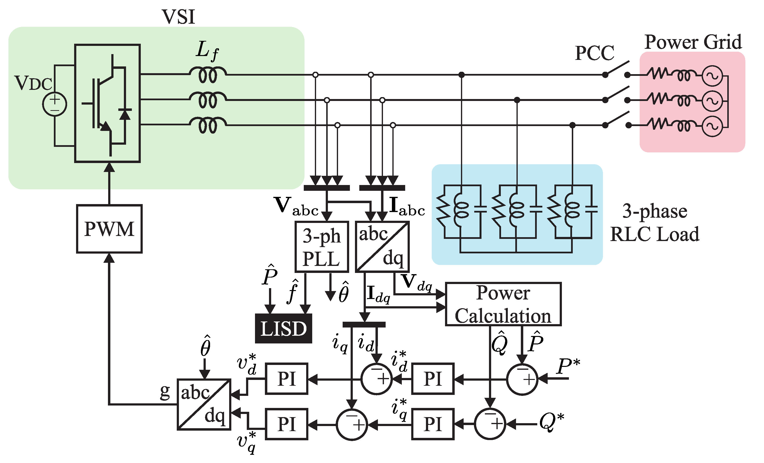
9] considered the dynamics of load switching scenarios, grid faults, and the interaction of multiple DGUs. Despite the differences, all reported test-beds comprise one or multiple DGUs feeding a single three-phase RLC load in a grid-connected configuration as showed in
Figure 2.
In an attempt to aggregate the reported test conditions, the proposed test protocol consists of five different cases [
9]:
Case 1: Simple disconnection event with a single DGU.
Case 2: Large load integration in grid-connected mode.
Case 3: Non-linear load integration in grid-connected mode.
Case 4: Voltage dip on the supply system.
Case 5: Simple disconnection event in a multi-inverter system.
The details about each case study are analyzed next so that the detection time and false island detection results can be compared under fair conditions. As the test-bed and its parameters are those used in [
9], the obtained results would be directly comparable to that work. Moreover, the results in [
9] were proven superior to another typical detection approach proposed in [
23], making the comparison twofold. As the used test-bed is the one recommended by the IEEE Std. 929 and IEEE Std. 1547 [
14,
15], the present results could be compared in the future with new proposals.
4.1. Case 1: Simple Disconnection Event with a Single DGU
The disconnection occurs at a specific time during the test. By opening the PCC, the single interfaced DGU assumes the task of feeding the connected RLC load. For this disconnection scenario, it is expected that the tested LISD triggers an islanding signal within the 2 s according to the IEEE standard 1547 [
14].
4.2. Cases 2 and 3: Load Integration in Grid-Connected Mode
The incorporation of new loads, especially large and nonlinear loads, can cause small frequency ripples when connected to the microgrid, even in a grid-connected configuration. Those ripples may trigger a false islanding signal.
In more detail, case 2 integrates a large load equal to half of the original power demand, while case 3 integrates a three-phase rectifier feeding a load equal to half of the supplying power demand (nonlinear load integration). Both tests integrate their corresponding load at a specific instant. It is the objective of this case to evaluate if the proposed algorithm can avoid producing false tripping signals due to the caused frequency ripples.
It is important to highlight that in island detection strategies that require some comparison against a specific threshold, false tripping is possible during load variations. In the context of the proposed LISD, the frequency ripple created due to the load integration leads to variations in the estimated droop characteristic of the generator. Then, false tripping could occur if is set incorrectly. Such threshold can be obtained by executing this test and obtaining the maximum variation of .
4.3. Case 4: Voltage Dip on the Supply System
Case 4 treats with the effect of any grid faults that do not cause an islanding event, a common fault is that of low-magnitude, sudden voltage dips, affecting the delivered voltage with little to no effect on the delivered frequency. For that matter, any islanding algorithm should be capable of avoiding false tripping during voltage dips.
4.4. Case 5: Simple Disconnection Event in a Multi Inverter System
The presence of multiple DGUs can significantly change the dynamics of a microgrid. During islanding events, all DGUs must trip to sustain a reliable operation during and after the transition event. Due to communication dependencies, any islanding event signal can be delayed or even lost in large microgrids. As the LISD proposal is decentralized, this case tests if many interacting DGUs are capable of tripping, considering that communication does not exist among them. A four-DGU system is tested to evaluate the performance of the proposed LISD in a multi-inverter arrangement. Each inverter is equipped with its own LISD.
5. Simulation Results
All the described simulation cases are carried out using the
Specialized Power Systems toolbox of
MATLAB Simulink, using the parameters listed in
Table 2. Notice that, as depicted in
Figure 2, the load considered is a parallel RLC load having its resonance frequency
matching that of the local utility operating frequency. This is assumed to be the worst-case scenario for successful detection of unintentional islanding [
9]. The voltage’s amplitude, frequency, and the variations of
were acquired and plotted. In the simulation,
is not latched when the island condition is detected, allowing the visualization of
changes after the disconnection event and during island operation. All simulated tests were programmed to disconnect from the main grid or modify the existing loads at
s after the system reached steady state.
The
threshold was set to a constant value (
as will be later explained) for all simulation results. As described in
Section 4, it can be obtained by executing the test related to case 2. A more in-depth description is given in the results below. It is essential to notice that the proposed LISD is not constrained to operate in some load range and that the installed load value is not necessary for the LISD operation. As this algorithm evaluates the grid’s stiffness,
would remain a valid metric in different load ranges as long as the island and grid-connected operation regimes exhibit different power-frequency slopes.
5.1. Case 1: Islanding Detection with a Single DGU
The first simulation scenario consisted of a simple disconnection event. The microgrid was disconnected at
s from the main power grid, leaving all power-feeding requirements to the DGU. The performance of the LISD is shown in
Figure 6. The disconnection event clearly affected the system’s frequency and the proposed island detection algorithm was triggered at
s, i.e., with a delay of 14 ms. It can be seen that further frequency variations would have again triggered the detection algorithm. However, one can latch the first tripping signal and exert the compensation mechanisms from that point on.
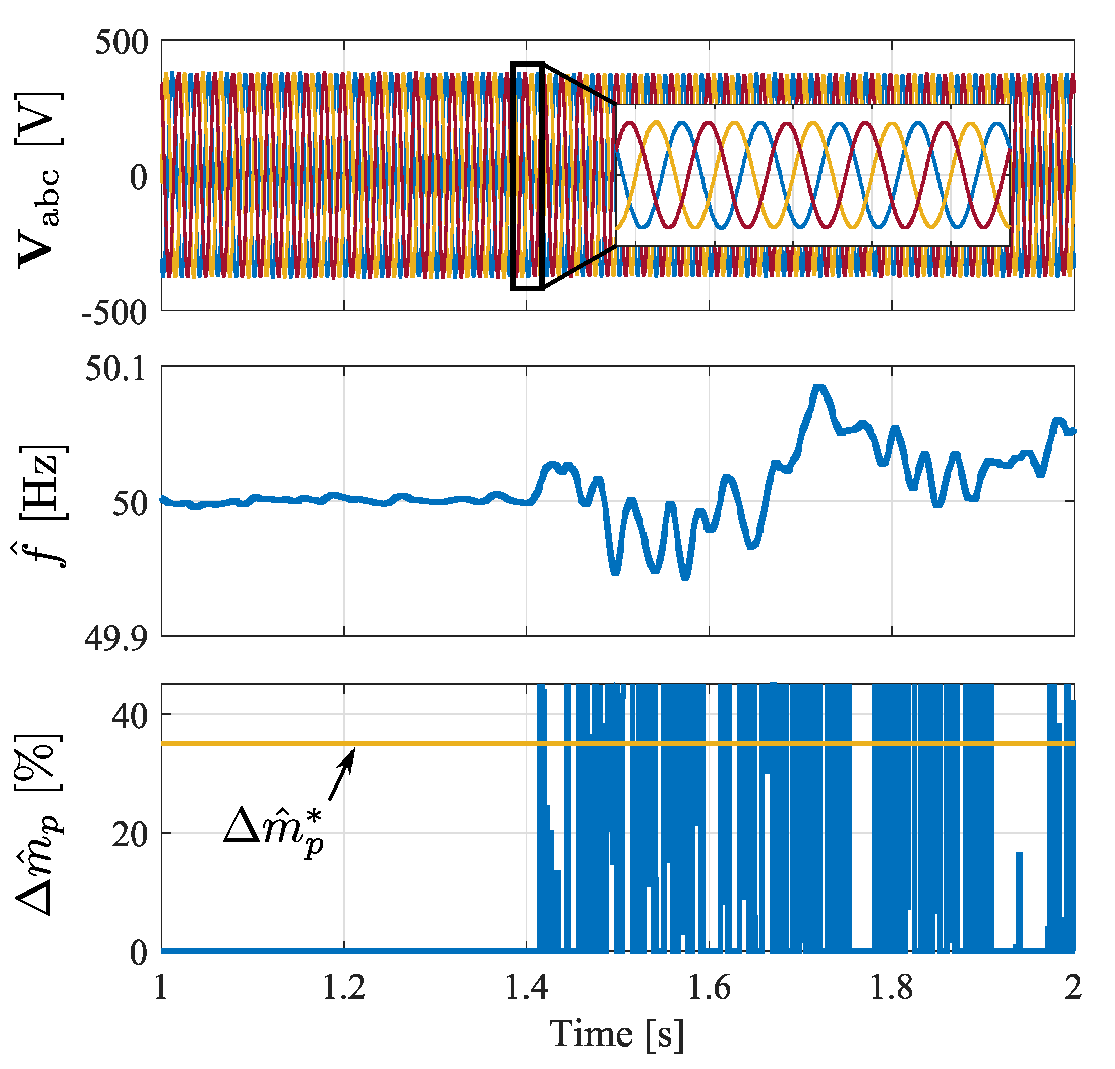
5.2. Cases 2 & 3: Load Integration
The system’s load was first increased by
according to the parameters in
Table 2. As shown in
Figure 7, the
variations caused by the large load integration raised to 30%. Then, to avoid false tripping signals caused by load variations, the threshold value
must be above 30%. Out of this,
was set to 35% as illustrated in the presented results.
As discussed above, it is recommended to first analyze the grid to find its usual and weigh load variations to find admissible values. Instead, and as done in this work, the threshold can be set after running simulations considering critical variations. It is essential to consider that would vary depending on n, , , and the grid parameters; as a result, it would be difficult to derive it analytically. In this case, the simulated approach was preferred.
Similarly, case 3 considered the integration of a nonlinear load, and its results are shown in
Figure 8. The nonlinearity of the rectifier exhibited a negligible effect on the performance of the proposed algorithm. In this case, the estimated droop characteristic does not show a significant jump in the estimated slope change
that could trigger any false islanding signals. Thus, neither of the tested scenarios that dealt with the integration of a large load or nonlinear load triggered a false positive signal during these tests.
5.3. Cases 4: Voltage Dip
Figure 9 shows the performance of the LISD after a voltage dip of
p.u. occurred (as tested in [
9]). As shown, the estimated frequency did not change drastically; therefore, there is no change in the estimated droop characteristics of the DGU. As the proposed algorithm deals with frequency and power variations and not directly with the voltage levels, the LISD did not trigger a false islanding signal, exhibiting reliability in the case of low magnitude grid faults. Recall that
only changes if the variation is “relevant.” Then, even in the presence of frequency variations,
would not necessarily change if
is not surpassed as discussed around (
7).
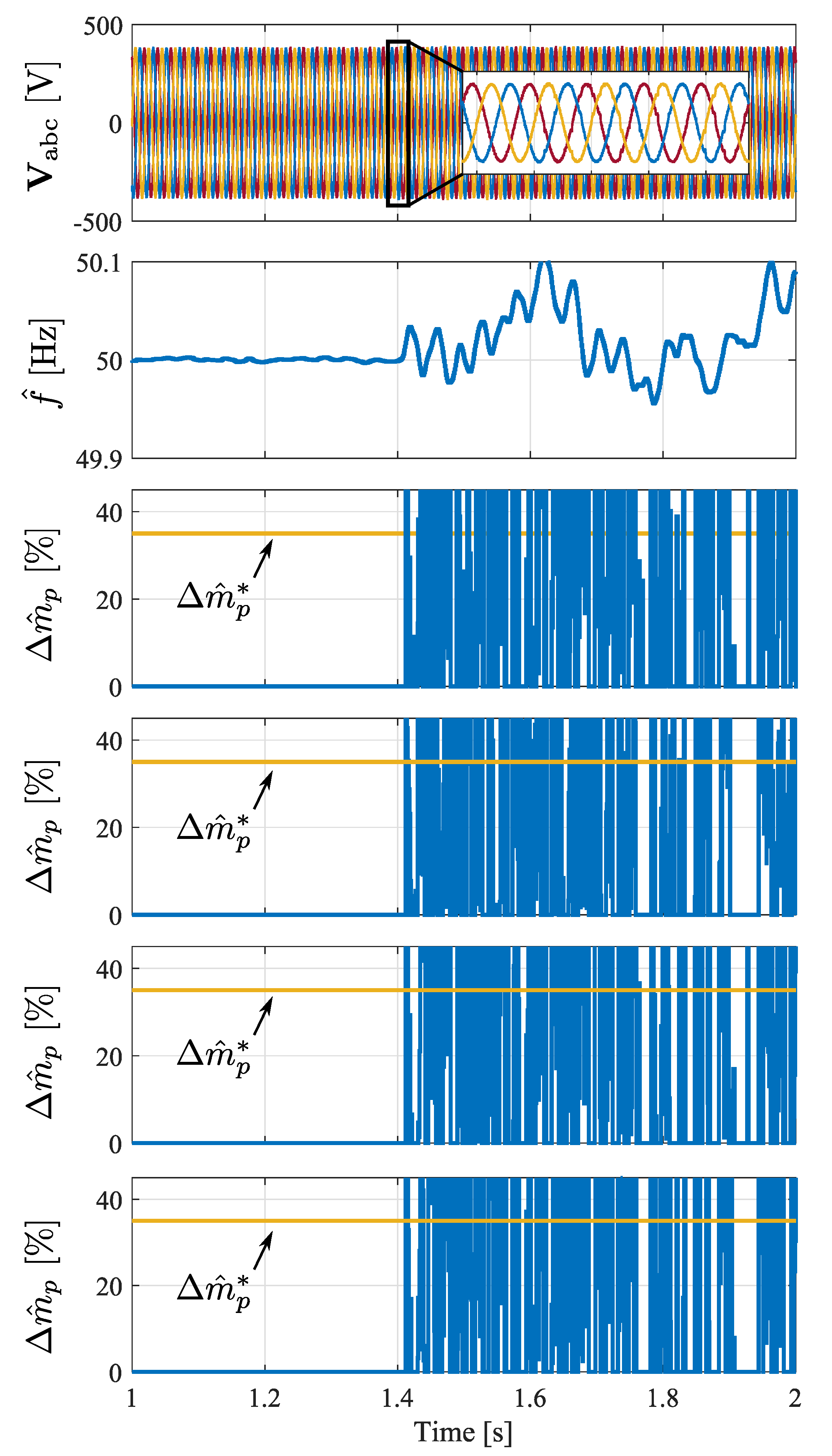
5.4. Cases 5: Island Detection in Multiple Inverter System
Figure 10 shows the result of the islanding test in the multiple inverter configuration. The proposed LISD algorithm was equipped locally at each inverter system (four in total), and each was capable of detecting the islanding event by calculating an individual
using the variables locally available at the DGUs outputs. The islanding signal was triggered at
ms, exhibiting a 12 ms delay after disconnection. The performance of the LIDS was slightly faster in a multiple invert system due to the added variations by other inverter systems in the microgrid. It is important to mention that, the impedance values corresponding to each of the DGU are taken from [
24] as the authors suggest such values to conduct validation tests in a multi-inverter configuration.
Indeed, the correct performance of any islanding detection algorithms is crucial in a multiple DGU system due to the different dynamics of each contributing agent. It is also important that no counteraction occurs between DGUs, as in the case of ADMs that can introduce electrical disturbances that can have an effect on other electrical agents connected to the microgrid. Thus, the proposed algorithm detected the disconnection locally, without relying on communication lines nor introducing other electrical disturbances into the microgrid’s main bus. The LISD is a noninvasive implementation that can be attached to the DGU. Nonetheless, the threshold value adjusted in case 2 needs to be properly set to avoid any false tripping signals in such conditions.
6. Experimental Validation
The experimental component in this work consists of
hardware in the loop (HIL)
real-time (RT) simulation test-bed. Two RT systems are interconnected via their analog I/Os. The first RT simulator is an OP5700 from OPAL technologies [
25], this simulator runs and controls the system described in
Figure 1 but not the LISD blocks. The second RT simulator is a Boom-Box by Imperix [
26], ideal for rapid control prototyping and validation of diverse power electronic applications. This simulator is in charge of running the proposed LISD algorithms separately. The relevant signals are acquired with an oscilloscope.
The OP5700 is programmed to have a user-controlled switching signal to dis/connect the main grid at the PCC, or to trigger the loads’ integration. This switching signal also triggers the oscilloscope using a digital output, collecting three-phase voltages and islanding signals. The primary control of the DGU is fed in a loop-back configuration through the multiple analog I/O ports of the OP5700. The active power and frequency signals are also taken from the analog output ports and connected to an Imperix proprietary interface, operating as the communication bridge between both systems. Finally, the OP5700 is programmed to run at 50 µs step time, i.e., the solver timestep (not to be confused with , which is managed at the Boom-box).
On the other end of the experimental validation, the Imperix Boom-Box receives the active power and frequency signals required for the operation of the proposed LISD. The proposed algorithm runs at a step time of
ms and outputs the islanding signal if such conditions are detected. This signal is carried out through a single analog output port and fed to the oscilloscope for precisely finding the delay time.
Figure 11 shows the experimental configuration and connections between RT time simulation platforms.
Case 1 was carried out as the first experimental validation test, consisting of a triggered disconnection. The Boom-Box RT system did output the islanding signal exactly 25 ms after the disconnection event as shown in
Figure 12. Since the triggering signal occurs at
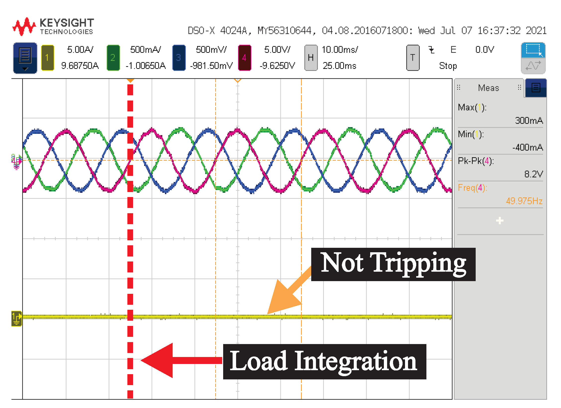
, a manual offset was used to align the rising islanding signal to the horizontal center of the oscilloscope, then obtaining the delay time as the horizontal offset. Subsequently, the load integration tests were performed in the same manner, again acquiring the islanding signal coming from the Boom-Box RT simulator. In both cases, the integration of an external load did not trigger a false islanding signal as shown in
Figure 13 and
Figure 14 (three-phase parallel load and nonlinear load integration, respectively). This indicates that the proposed LISD algorithm can withstand large load switching events without tripping.
Lastly, a multi-inverter system was tested, consisting of four voltage synchronous inverters operating on a constant power control scheme while feeding a 32 kW load (the rated power was multiplied by the number of DGUs). Each inverter is tasked to deliver a constant power output of 8 kW, and their output impedances are set to be different to represent different locations of DGUs (see
Table 2). In this case, only the active power and frequency values of three DGUs were fed into the BoomBox due to the availability of I/O ports; therefore, only the islanding signal of these particular DGUs is graphically shown.
The four islanding signals were triggered after 27 ms (DGU1), 32 ms (DGU2), 40 ms (DGU3), and 40 ms (DGU4). The acquired signals from the first three DGUs are shown in
Figure 15. It is noteworthy that the delay time seems to be associated with the distance from the PCC to the DGU, and that the simulated unit (DGU4) yielded the same delay as DGU3, both sharing the same output impedance. Each of the islanding signals was generated by monitoring only the local power and frequency measurements of each inverter. These results indicate that each DGU is capable of identifying the disconnection event even in a multiple inverter configuration without external communications.
Table 3 shows a summary of the reported results compared to the work presented in [
9], addressing a hybrid islanding detection algorithm based on voltage unbalances and total harmonic distortion. This comparison is relevant because the authors have compared their proposal to other hybrid detection methods and tested their islanding algorithm under the same simulation scenarios presented in
Section 4. Therefore, the LISD was validated as an improved detection mechanism over previously presented methods.


