Article

Energetic and Exergetic Performances of a Retrofitted, Large-Scale, Biomass-Fired CHP Coupled to a Steam-Explosion Biomass Upgrading Plant, a Biorefinery Process and a High-Temperature Heat Network

1
Thermo and Fluid Dynamics (FLOW), Faculty of Engineering, Vrije Universiteit Brussel (VUB), Pleinlaan 2, 1050 Brussels, Belgium
2
Brussels Institute for Thermal-Fluid Systems and Clean Energy (BRITE), Vrije Universiteit Brussel (VUB) and Université Libre de Bruxelles (ULB), 1050 Brussels, Belgium
3
Onyx Power, Missouriweg 69, 3199 LB Maasvlakte, The Netherlands
4
Arbaflame, Henrik Ibsens Gate 90, 0255 Oslo, Norway
5
Department of Chemistry, University of Bergen, Allégaten 41, 5007 Bergen, Norway
*
Author to whom correspondence should be addressed.
Energies 2021, 14(22), 7720; https://doi.org/10.3390/en14227720
Submission received: 15 September 2021 / Revised: 1 November 2021 / Accepted: 11 November 2021 / Published: 18 November 2021
(This article belongs to the Special Issue Advanced Bioenergy and Biorefinery Process)

Abstract

:
This paper aims at assessing the impact of retrofitting an existing, 730 MW e , coal-fired power plant into a biomass-fired combined heat and power (CHP) plant on its energetic and exergetic performances. A comprehensive thermodynamic model of the power plant was developed and validated against field data, resulting in less than 1% deviation between the model and the measurements for the main process parameters. The validated model was then used to predict the behaviour of the biomass CHP after retrofitting. The modelled CHP unit is coupled to a steam-explosion biomass upgrading plant, a biorefinery process, and a high-temperature heat network. 13 scenarios were studied. At constant boiler load, delivering heat to the considered heat clients can increase the total energy efficiency of the plant from 44% (electricity only) to 64%, while the total exergy efficiency decreases from 39% to 35%. A total energy efficiency of 67% could be reached by lowering the network temperature from 120 °C to 70 °C. Identifying the needed heat clients could, however, represent a limiting factor to reach such high efficiencies. For a constant power demand, increasing the boiler load from 80 to 100% in order to provide additional heat makes the total energy efficiency increase from 43% to 55%, while the total exergy efficiency decreases from 39% to 36%.

1. Introduction

The European Union recently adopted the new target of reducing their CO2 emissions by at least 55% by 2030 [1,2]. As it is currently the main source of renewable energy around the world, numerous climate change mitigation scenarios show that bioenergy will keep playing an important role in the future, sustainable energy mix [3,4,5,6]. As a dispatchable source of renewable energy, it is expected to play a key role in supporting intermittent renewables for electricity production, and in providing high temperature heat [7]. The combined production of heat and power (CHP) is also seen as the most promising way to use this resource. As a carbonaceous solid fuel, solid biomass can be used as a surrogate for coal in existing power plants. Retrofitting coal-fired boilers to biomass combustion is indeed an effective way of taking advantage of available assets to produce green energy. It can generally be achieved through limited adaptations of the equipment [8,9].
The thermal pre-treatment of biomass can even improve the physical and chemical characteristics of the fuel. The characteristics of the pre-treated fuel then resemble those of coal, which facilitates the plant conversion [10].
Several coal-fired power plants were already converted to biomass co-firing [10]. Full conversions are also described in the scientific and industrial literature [10,11]. In these cases, power derating is often reported after conversion. However, very limited information is available on the (energy and exergy) efficiencies reached after retrofitting, which hinders the assessment of the potential contribution of such retrofitted plants to the energy transition. It can anyway be argued that the relatively old power plants retrofitted in the past are not representative for the performances that could be reached by retrofitting more recent, state-of-the-art power plants. Furthermore, information on the increase of efficiency potentially achieved by a switch to a combined production of heat and power CHP is scarce [10,11].
In order to bring new knowledge on the achievable performances of state-of-the-art biomass retrofits, the EU-funded Arbaheat project was launched in 2018, with the aim of developing and demonstrating the cost-effective retrofitting of modern fossil fuel-driven power plants into biomass-fired CHP plants, featuring, in addition, the integration of the biomass steam-explosion pre-treatment process as a heat client [12]. The power plant studied in the Arbaheat project is an ultra-super-critical (USC), coal-fired power plant. In the developed process, the steam-explosion plant is coupled to the power plant by using steam extracted from the steam turbine for the pre-treatment of the fuel. The condensate collected from the steam-explosion process is then valorized in a biorefinery process to extract valuable substances. Steam extraction is also used to deliver heat to external clients such as industries, green houses and buildings, via a large-scale heat network. The overall process is illustrated in Figure 1. In order to assess the performances and the economic viability of such a retrofit, the efficiency of the whole process must be accurately predicted for various power and heat production scenarios. A significant part of the Arbaheat project is therefore dedicated to the detailed thermodynamic modelling of the biomass-fired CHP and its heat clients.
This paper presents the results of the detailed analysis of the impact of the proposed retrofit on the energetic and exergetic efficiencies of the plant. A comprehensive Thermoflex® model of the power plant was developed and validated against historical data and new performance tests performed with biomass. The model was then adapted to predict the performances of the whole CHP system for various loads and various heat demands from the internal and external heat clients.
The studied power plant is described in Section 2.2, while Section 2.3 presents the developed thermodynamic model and its validation, including the consideration of component aging. Section 2.4 is dedicated to the adaptation of the model to biomass-firing and CHP operation, including the definition of the internal and external heat clients. The scenarios studied in the scope of this paper are defined in Section 2.5, and the simulation results are presented and discussed in Section 3.

2. Materials and Methods

2.1. Materials

In the framework of the Arbaheat project, it is proposed to retrofit the power plant to 100% biomass firing, under the form of steam-exploded pellets. The composition of the reference pellets considered in this study is given in Table 1. Steam-explosion is a commercially available process consisting of breaking the rigid biomass fiber structure by submitting it to elevated pressure (1–3.5 MPa) and temperature (180–240 °C) for several minutes, followed by an explosive decompression before pressing the mass into pellets. This increases the energy density of the pellets. It also improves their durability, their grindability, and their pneumatic transport properties [13,14,15]. Steam-exploded pellets are also hydrophobic [14,15]. As a consequence of these improved characteristics, the main modifications to be brought to the power plant are the adaptation of the mill classifiers and the explosive resistance of the mill housing. The main disadvantage of upgraded biomass fuels is their higher production costs. It can, however, be counterbalanced by lower investment costs and the additional production of heat and/or valuable chemical compounds released during the pellet production process [16].

2.2. The Power Plant

The power plant studied in this work is a modern ultra-super-critical (USC), coal-fired, 730 MW e 
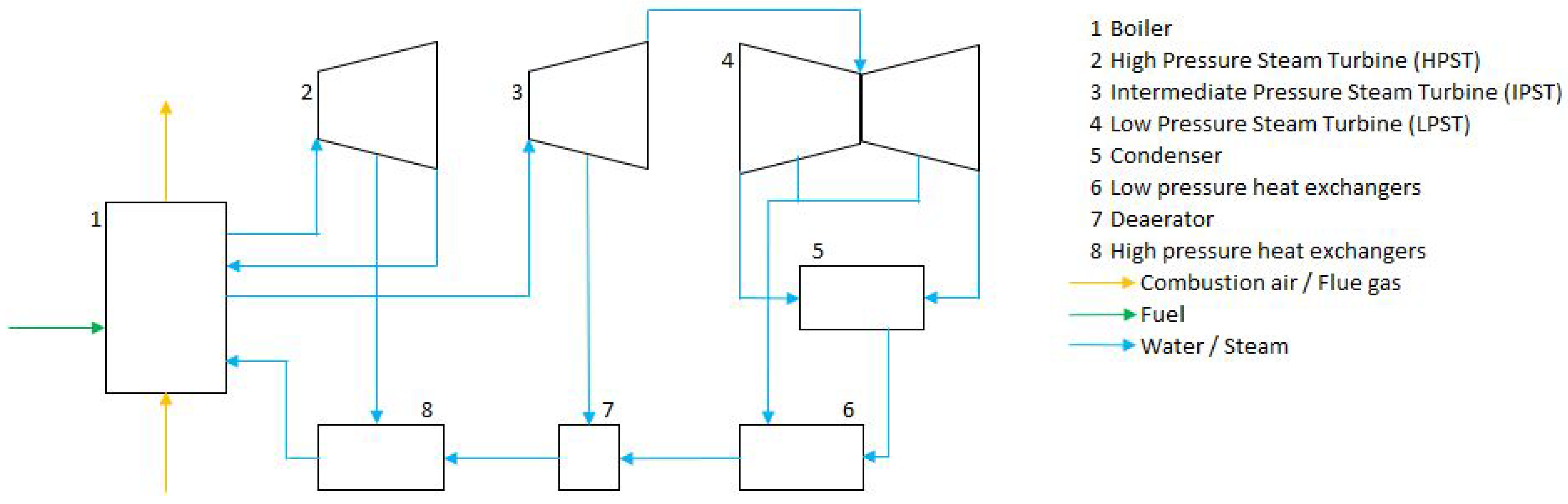
power plant. Its nominal, net electrical efficiency is 45%. The plant was commissioned in 2015. The generator is driven by a steam turbine composed of one high-pressure, one intermediate-pressure and two diabolo-type, low-pressure steam turbines. The expanded steam is then condensed in two water-cooled condensors, and the feedwater then flows through five low-pressure preheaters, a deaerator, and three high-pressure preheaters, driven by several pumps. The 1550 MW t h , USC boiler features an economiser, an evaporator (“Evaporator” is the customary term for the radiative heat exchanger in the furnace, although the cycle is supercritical in this case and, therefore, does not present an evaporation phase as such), three superheaters, and two reheaters. The live steam parameters at the outlet of the superheaters are 252.2 bar and 600 °C. At the outlet of the reheaters, they are reduced to 61 bar and 620 °C. The combustion air, pressurised by two forced draught (FD) fans, flows through a rotating air preheater. An induced draught (ID) fan entrains the flue gas through state-of-the-art flue gas treatment (FGT) systems: a selective catalytic reduction (SCR) denitrification system, an electrostatic precipitator for dust removal, and a wet scrubber to reduce the SO x emissions. Coal is pulverised in four roller mills, each of them feeding a row of four low-NO x burners in an opposed-type arrangement. The boiler is also equipped with an over fire air (OFA) system for the further reduction of NO x production in the furnace through global air staging. Figure 2 presents a simplified schematic of the steam cycle.

2.3. Thermodynamic Modelling and Validation

Thermoflex®, the most flexible and adaptable package of the Thermoflow® software, is an energy and mass balance engineering tool performing static simulations of power production facilities, such as coal-fired power plants, gas-fired power plants, or solar power plants. The thermodynamic design of a power plant is based on the combination of predefined components. If the system components are carefully defined and connected, Thermoflex® computes the full heat and mass balance and the performances of the system, based on a series of thermodynamic design assumptions. A second step consists of switching to engineering design mode. In this mode, Thermoflex® translates the initial, basic thermodynamic design assumptions into equipment design assumptions. These assumptions can be adapted by the user in order to fit actual data. After computation, it results in physical equipment design, including technical specifications and costs, as well as in updated heat and mass balance, and plant performances that are consistent with the defined equipment design. The last step of the detailed modelling of a power plant is performed in the off-design mode. In this mode, the equipment physical design and technical specifications are locked. Set points that differ from the base case are then defined, and the final heat and mass balance, plant performances and costs are calculated. This mode therefore allows for the simulation of various loads. A very useful feature of Thermoflex® for this last phase is the possibility to create a functional interface between the model and a spreadsheet (Elink). It allows the computation of various cases by defining specific inputs to be varied and outputs of interest.
In order to investigate the impact of the retrofit of the studied coal-fired power plant into a large-scale, biomass-fired CHP plant, a detailed and representative model of the existing power plant needs to be developed. Thermoflex® models were first developed based on the original design and operational data of the power plant. As all loads cannot be covered by a single model, several parameters have to be adapted and fine-tuned for lower loads to get representative results. The obtained models were validated against field data from the acceptance tests performed during the commissioning of the power plant; see Section 2.3.1. Since the commissioning in 2015, component aging has, however, led to a slow degradation of the plant performances. Using recent operational data, the developed models were therefore fine-tuned to reproduce the current performances of the plant, leading to new versions of the models taking aging into account; see Section 2.3.2. As a last step of the thermodynamic modelling of the existing plant, biomass co-firing was modelled and validated against tests performed in the framework of the Arbaheat project for a 22% biomass share; see Section 2.3.3. These results will then be extrapolated to 100% biomass firing, together with the addition of the internal and external heat clients, see Section 2.4.

2.3.1. Original Performances

A base-case model has been developed using the original technical information and operational data from the power plant. Its purpose is to reproduce the net performances of the power plant after its commissioning, for various loads. In order to accurately reproduce them, the base-case model is comprehensive: it covers all systems of the power plant, including the flue gas treatment systems, and all auxiliary equipment, such as auxiliary pumps, fans and heat exchangers. Overall, it consists of more than 180 components, 285 links and 1500 variables.
This model was validated against the data from the official acceptance test performed in December 2014 by an accredited third party, using a combination of available measurements retrieved from the power plant’s control system and specific, additional measurements. All measurement tools were calibrated before the test. The performance tests covered the following loads: maximum continuous rating (MCR) and boiler maximum continuous rate (BMCR). MCR is defined as the maximum rating of the plant under normal and continuous operations in natural sliding pressure mode, with steam generator and steam turbine being ready to provide primary frequency control as required, and with boiler in normal operating mode including blowdown and auxiliary steam consumption. BMCR is defined at reference conditions as the maximum rating at which the boiler is able to operate under normal, continuous operating conditions for any coal from the design range. It is defined as 103% of the MCR.
During such an acceptance test, the power plant is operated in well-reported conditions, which never perfectly match the standard conditions for which the expected performances were assessed. The tests results are therefore adapted using correction curves provided by the manufacturer. For the power plant studied here, corrections are available for the following variables:
  • Ambient temperature
  • Cooling water inlet temperature
  • Aging
  • Generator power factor
  • Cooling water mass flow
  • Fuel moisture content
  • Fuel ash content
  • Ash reflection factor
Modelling a large power plant never results in a perfect match between the simulation results and the field data, due to an unavoidable discrepancy between the modelled components and their actual behaviour. The limited accuracy of the performed measurements also introduces additional uncertainty. In addition, choices need to be made in terms of the main parameters of interest, for which the discrepancy between the model and the field data is minimised during the fine tuning and validation process. A (relatively) larger discrepancy is tolerated for other, secondary parameters. It is of course important to take this into account when interpreting the simulation results, by avoiding drawing firm conclusions on the variations of secondary parameters. The main parameters used here to validate the developed thermodynamic models are:
  • Gross power
  • Fuel input
  • Condensor pressure
  • Live steam parameters: temperature, pressure and steam flow
  • Oxygen content in the flue gas
When these parameters are within the acceptable deviations described in the standard DIN1943 dedicated to thermal acceptance tests of steam turbines, a model is considered as validated. These acceptable deviations vary with the measured parameters. The fine-tuning of the model was carried through careful adjustment of the technical parameters of the key pieces of equipment, resulting in light deviations from their design values (order of magnitude lower than 1%), see the results in Table 2. The main parameters that were adjusted were nominal flows, cleanliness factors, fouling factors, pump characteristics, mechanical losses, rotor angles, leakage flows, heat transfer coefficients, or heat exchanger surfaces, among others. This of course represents a labour-intensive and time-consuming task, that can only be achieved with a deep understanding of the operation of the plant. In the future, the use of uncertainty quantification (UQ) [17,18] techniques should be investigated to automatically reconcile the model parameters with the field measurements, taking into account the related uncertainties. To the best knowledge of the authors, the application of these techniques to models featuring such a high number of parameters (>1000) requires further research.
In addition to the acceptance tests performed at MCR and BMCR, the base-case model was also validated against operational data retrieved during normal operation after the commissioning, at various loads: 100%, 75%, 50%, 30% and 25%. The deviations for the main parameters for the lower loads were less then 1%.

2.3.2. Current Performances: Steam Turbine Aging

With time, processes such as fouling, erosion or wear lead to a decrease of the performances of some pieces of equipment. This overall slow degradation process is often referred to as aging. In particular, steam turbine aging has a significant impact on the overall plant performances [19]. Other pieces of equipment, such as heat exchangers, are also submitted to variations of their performances with time, but these are also strongly impacted by the operational conditions of the plant, especially in solid fuel-fired boilers. Variations of the fuel characteristics (properties of the inorganic compounds, among others), variable soot blowing system operations, or acceptable, temporary leakages can impact the heat and mass balance of the boiler.
In the frame of this study, steam turbine aging was assessed and integrated into the thermodynamic model of the plant to match recent field data. To do so, the heat exchange parameters in the boiler also had to be adjusted, although it is not considered as resulting from an aging process, strictly speaking.
Base load tests are performed at the power plant on a regular basis. These so-called P m a x tests are carried out during stable runs of at least 15 min. All the data necessary for the assessment of the plant performances are then gathered from the control system. The P m a x test used in the frame of this work was carried out during winter 2019, as it presented the highest reliability among the most recent tests. It must therefore be considered that the performances of the plant are predicted at this moment. The extrapolation of the aging process is out of the scope of this study, but will be subject to future works.
In order to assess the decrease of the steam turbine performances for a given lifetime, the model first needs to accurately predict the corresponding inlet steam parameters. The boiler heat and mass balance parameters were therefore adjusted to reach a discrepancy lower than 1% between the model prediction and the considered P m a x test. The steam turbine dry stage efficiencies were then adjusted to reproduce their performances for the measured input steam parameters, which lead to a quantification of an aging factor for each turbine. The resulting factors are given in Table 3. The final deviation between the full model and the P m a x test results is less than 1% for the key parameters (Table 4).

2.3.3. Biomass Co-Firing

In the beginning of the project, one of the four roller mills was adapted to carry out co-firing tests and gather information about the impact of a full switch. During these tests, an overall share of 22% of steam-exploded pellets (mass-based) was reached. The co-firing tests took place during summer 2019. They aimed at testing several systems: fuel handling, fuel milling, combustion and flue gas treatment, among others. It was also an opportunity to assess the impact of biomass co-firing on the performances of the power plant. The key information retrieved from these tests in this regard concerns the impact of biomass co-firing on the overall, radiative heat transfer in the furnace, that cannot be predicted based on the fuel characteristics. In Thermoflex, the parameter ruling the amount of radiant heat flux from the furnace directly transferred to the radiant superheaters was adjusted to match the overall performances of the plant with the same accuracy as for coal-firing. The observed evolution of this parameter was extrapolated to predict the performances of the plant for 100% steam-exploded pellets firing; see Section 3.

2.4. The Biomass-Fired CHP

The main objective of the present study is to predict the energetic and exergetic performances of the plant after its retrofit into a biomass-fired CHP coupled to three different heat clients: a steam-explosion plant used for the pre-treatment of the biomass, a biorefinery process extracting valuable chemical compounds from the produced condensate, and an external, large-scale heat network. In this Section, a way in which live steam can be extracted from the turbine to deliver high-temperature heat is described. The heat clients considered in this study and the related heat demands are also defined. Finally, the methodology that will be used to optimise the steam extraction in function of various heat demand scenarios is presented.

2.4.1. Steam Extraction Points

The steam turbine was originally designed to allow steam extraction for district heating (DH) purposes. Three extraction points are available: from the HP turbine outlet (cold reheat line), from the IP turbine outlet, and from the LP turbine. The latter extraction point is specifically designed for large flow rates, unlike the four other, conventional steam extraction points from the LP turbine delivering heat to the feedwater preheaters, in order to increase the efficiency of the steam cycle. The turbine manufacturer predicts that the turbine could deliver 150 MW t h of thermal power to a DH network at MCR, assuming a supply temperature to the network of 180 °C and a return temperature of 80 °C. The delivered thermal power and the related energy and exergy efficiencies are of course very much dependant on the power plant load, as well as on the heat demand and the temperature levels required by the heat clients. This design value can therefore not be generalised, and detailed simulations must be carried out to assess the performances of the CHP in the conditions of interest for this project, which is precisely the purpose of this study.
The maximum steam extraction flow rates from the turbines are a function of the turbine inlet flow rates. Although the blades located upstream of the tapping points are reinforced, the relative extraction flow rates are limited by the acceptable loading of the turbine stages, especially at high loads. This results in maximum extraction flow values which correspond to a boiler load around 80%. These maximum extraction rates will have a strong impact on the predicted performances of the CHP in the scenarios studied in Section 2.5. In the lower unit load range, the steam velocity at the extraction tapping point must be considered, as well as the minimum necessary steam flow through the last part of the LP turbine.

2.4.2. The Heat Clients

In this Section, the heat clients considered in this studied for the CHP operation of the plant are described. 
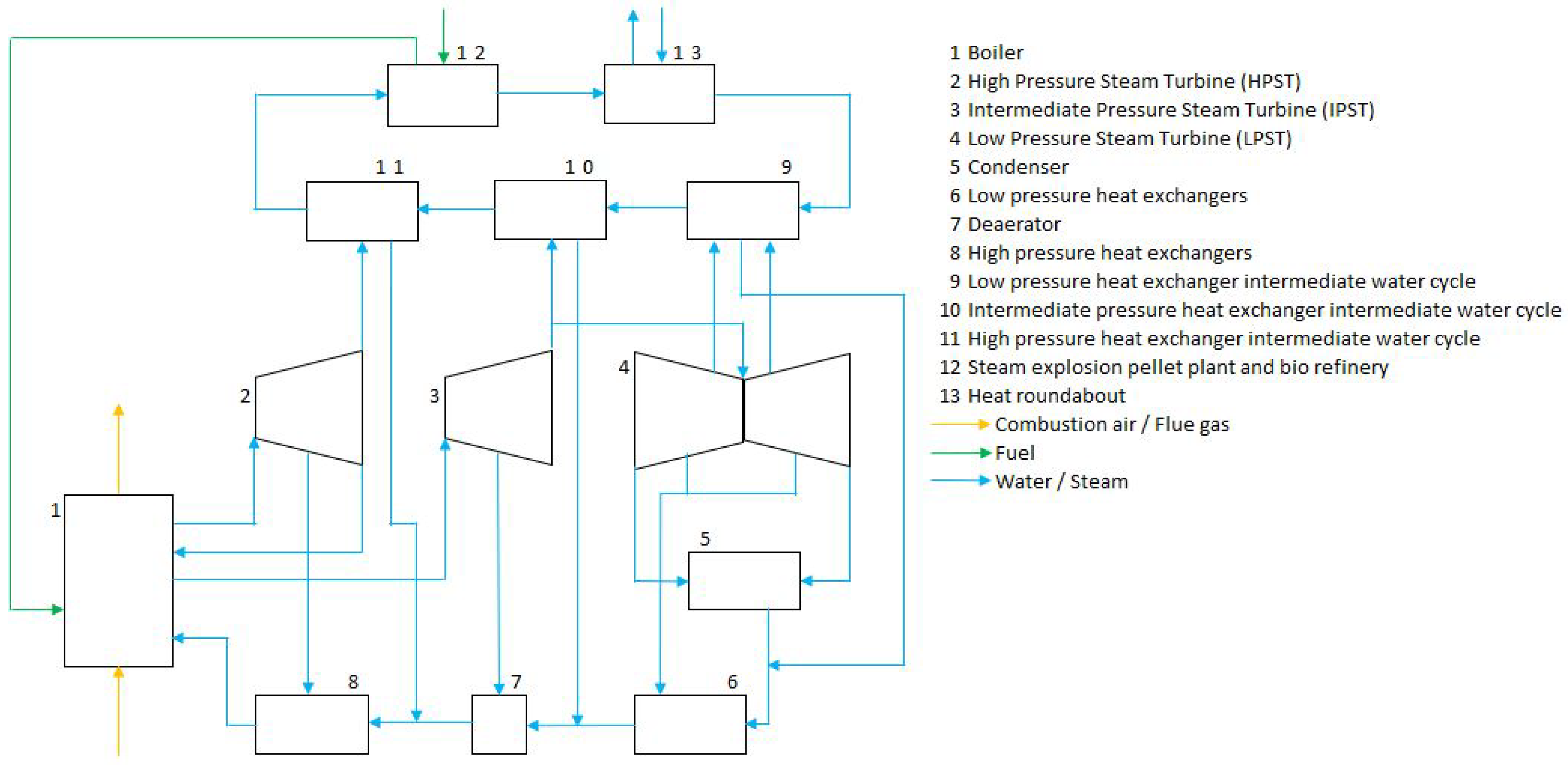
Figure 1 shows the general layout of the CHP system. Three heat exchangers (9, 10, 11) transfer heat from the steam extracted from the three tapping points (outlet HP, outlet IP and LP turbines) to an intermediate closed loop. This intermediate loop in turns delivers heat to internal heat clients (12) and to an external heat network (13).
The condensates flow back to the power plant. The return points were chosen very carefully, in order to guarantee that the pressure and temperature of the condensates are adequate at all loads. The following points were selected based on a worst case scenario (lowest load):
  • High pressure condensate flows back into the system between the booster pumps and the feed water pumps;
  • Intermediate pressure condensate flows back to the deaerator;
  • Low pressure condensate flows back in the feedwater stream behind the gland steam condensors.

2.4.2.1. Steam-Explosion Plant and Biorefinery

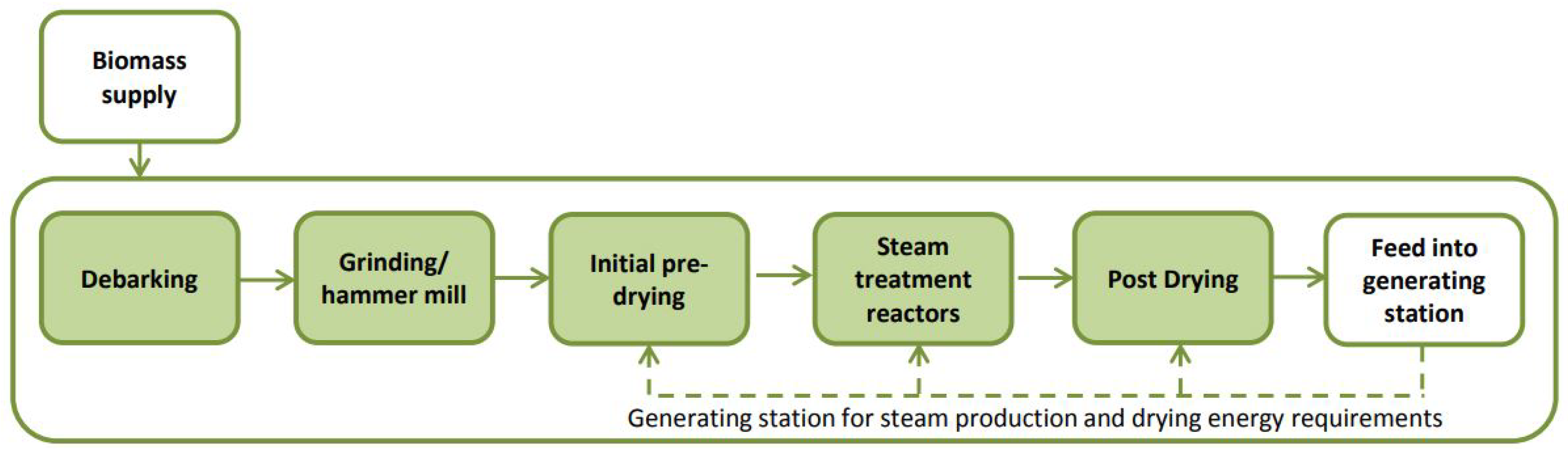
A state-of-the-art, full-scale steam-explosion plant designed by Arbaflame is coupled to the CHP to take advantage of the available steam. All the heat streams are studied in detail and integrated to make the plant as energy-efficient as possible. The various steps of the steam-explosion process are illustrated in Figure 3. The steam-explosion plant requires three different streams of saturated steam, at different temperature levels: for the steam-explosion process as such (222 °C), to heat up the reactor vessels jackets (165 °C), and for the post-drying step (198 °C).
The condensate released by the steam-explosion process can be valorized by extracting high-added value, bio-sourced chemical compounds such as furfural [15]. The studied biorefinery process leading to the production of such compounds is also considered here as an internal heat client for the CHP plant. It consists of several distillation columns, extractors, heat exchangers, pumps, among others. The required steam is saturated, at a temperature of 120 °C.
As its future purpose will most probably be to contribute to the grid stability while providing high-temperature heat with a high efficiency, the CHP plant is not expected to run continuously at full load. A realistic design for a full-scale pre-treatment plant installed on the selected site leads to an annual production of steam-exploded pellets around 700,000 t/y. It corresponds to a continuous steam demand of 29.6 kg/s, including the biorefinery process.

2.4.2.2. Heat Roundabout

The surplus of heat that is not consumed by the internal heat clients can be delivered to external clients through a heat network. As a first step of the Arbaheat project, potential clients were identified in the surrounding industrial and urban areas, and several scenarios were investigated for the development of such a network. Industrial processes as well as tertiary and residential buildings are the main potential clients. The furthest point of the network could be 40 km away from the plant. In summer conditions, a temperature of 100 °C would be required, with a return temperature of 60 °C. In winter conditions, a temperature of 120 °C should be reached, while the return temperature should be 70 °C. In the mid term, the total thermal power demand could reach 400 MWth peak, while it could increase to 2400 MWth peak in the long term. Local heat production plants installed along the network could support the CHP in fulfilling heat demand. The detailed operation of the network is, however, out of the scope of this paper. Our main purpose is to assess the efficiency of the CHP plant when it faces various heat demands from external clients, while running at various loads. This information is key to the evaluation of the various opportunities in terms of development and future extension of the heat network. We will therefore assess the maximum thermal power that can be provided to the network in various scenarios, providing it does exceed the maximum demand that was identified. The winter conditions are considered, i.e., supply and return temperatures of 120 °C and 70 °C, respectively.

2.4.3. Steam Extraction Optimisation

As explained in Section 2.4.1, the potential steam extraction points in the power plant are fixed by design: outlet HP, outlet IP and LP turbines. Determining the optimal extraction flow rates from these three points for a given scenario is not straightforward. A cascading principle was used: in order to maximise the exergetic efficiency of the plant, steam extraction from the LP turbine is favoured, provided that it meets the requirements in terms of temperature level in the heat exchangers of the intermediate loop, until the maximum allowable flow rate is reached. IP and HP steam flows are then subsequently used to fulfill the remaining demand.

2.5. Scenarios

The main objective of this paper is to assess the impact of the proposed retrofit on the energy and exergy efficiencies of the plant. To do so, a finite number of relevant scenarios were defined, both in terms of total load and thermal power demand. They are representative of the typical operation modes expected after the retrofit. The defined scenarios are summarised in Table 5.
In these scenarios, the plant runs at three different loads in terms of thermal input in the boiler: 100% (full load), 80% (maximum steam extraction load) and 25% (minimum load). The 80% load was selected because it corresponds to the maximum steam extraction flow rates from the turbines; see Section 2.4.1. All cases are based on 100% biomass firing.
The base cases correspond to pure electrical power production at each load. They will be used as references. Cases a to c are variants of the base cases, with 100% internal heat demand and no external demand, 100% internal heat demand and the highest possible external demand, and no internal demand with the highest possible external demand, respectively.
The last case is a variant of case 80 b , with lower requirements in terms of heat network temperatures, in order to reach a higher energy efficiency. The supply and return temperature for the external heat client are reduced to 70 °C and 30 °C, respectively.

2.6. Performance Assessment

Before discussing the results of the performed simulations, the relevant performance indicators must be accurately defined. As the retrofitted power plant will ultimately become a CHP unit, both an energetic and an exergetic analysis must be carried out.

2.6.1. Energy Efficiency

First of all, the net electrical efficiency η e l is defined as follows:
η e l = P e l , n e t P f u e l [ - ]
where P e l , n e t is the net electrical power delivered by the plant to the grid and P f u e l is the thermal power input in the boiler, calculated as the product of the fuel flow rate and its lower heating value (LHV). The gross electrical efficiency is based on the gross electrical power P e l , g r (including the electrical consumption of the auxiliary systems):
η e l , g r = P e l , g r P f u e l [ - ]
The total energy efficiency of the CHP plant is calculated by summing the produced electrical power and the delivered thermal power as two equivalent forms of energy:
η C H P = P e l , n e t + P t h P f u e l [ - ]
where P t h is the thermal power delivered to the internal and external heat clients. This thermal power can also be expressed as the sum of the thermal power extracted from the HP, IP and LP steam extractions:
η C H P = P e l , n e t + P H P + P I P + P L P P f u e l [ - ]
where P H P / I P / L P are the thermal powers extracted from the three pressure levels.

2.6.2. Exergy Efficiency

The total energy efficiency η C H P allows for an overall characterisation of the performances of the plant, but it does not distinguish between electrical and thermal powers in terms of quality of the delivered energy. The complementary notions of exergy and exergy efficiency should also be considered for a complete analysis of the performances of the CHP plant. The exergy of a system is defined as the amount of work that can be obtained from a system, given its imbalance with its environment [20]. The exergy efficiency therefore gives a reference in terms of quality of the energy. Electrical power is pure exergy, while the exergy content of a fluid is a function of its thermodynamic state. What can be described as the thermal component of the exergy of a system can be calculated as [20]:
ψ h e a t = ( h h 0 ) T 0 ( s s 0 ) [ kJ / kg ]
where h is the enthalpy, T is the absolute temperature, s is the entropy and the subscript 0 refers to the environment. In the frame of this study, the reference state of the environment is the atmospheric pressure and the temperature of the cold source considered in the simulations (9 °C).
In order to properly assess the exergy efficiency of a process, it is of course needed to compute both the exergy output and the exergy input. One generally considers that the exergy content of a fuel is very similar to its LHV. As the difference between the LHV and the exergy content can, however, differ by up to 30%, especially for solid fuels [20], we will here properly define and compute the exergy of the steam-exploded pellets considered in this study.
Unlike numerous gaseous fuels, solid fuels are not composed of well-known, basic compounds. This makes it difficult to determine their enthalpy and entropy with a reasonable degree of accuracy [20]. We will here use the correlations proposed by Kotas [20] to compute the ratio ϕ between the exergy content of a fuel and its LHV:
ϕ = ψ f u e l L H V [ - ]
For a dry solid fuel with an O/C ratio lower than 0.667 , Kotas [20] proposes the following correlation:
ϕ d r y = 1.0437 + 0.1882 m H 2 m C + 0.061 m O 2 m C + 0.0404 m N 2 m C [ - ]
where m X is the mass concentration of element X in the fuel. The following correction is proposed to account for the moisture and sulfur contents of the fuel when calculating its exergy content [20]:
ψ f u e l = ( L H V + 2442 w ) ϕ d r y + 9417 m S [ kJ / kg ]
where w is the moisture content of the fuel (as received). In the case of the considered steam-exploded pellets (see Table 1), ψ f u e l = 22 , 353 kJ/kg. The ratio ϕ between the exergy content and the LHV of the fuel is therefore equal to 1.09 .
The electrical exergy efficiency of the CHP can therefore be defined as:
η ψ , e l = P e l , n e t P ψ , f u e l [ - ]
where P ψ , f u e l is the exergy input of the fuel, calculated as the product of the fuel flow rate and its exergy content ψ f u e l . As the exergy content of the fuel is larger than its LHV, η ψ , e l will be lower than η e l .
The total exergy efficiency of the CHP plant η ψ , C H P is defined as:
η ψ , C H P = P e l , n e t + P ψ , t h P ψ , f u e l [ - ]
where P ψ , t h is the sum of the exergy fluxes delivered to the heat clients, calculated according to Equation (5). Unlike for energy, this flux cannot be calculated as the sum of the exergy lost by the streams of extracted steam, as a certain amount of exergy is destroyed in the heat exchangers of the intermediate loop.

3. Results and Discussion

Table 6 gives the main results of the simulations performed for the 13 scenarios defined in Table 5. The evolution of the energy and exergy efficiencies defined in Section 2.6 is illustrated in Figure 4.
As expected, η C H P is equal to η e l and η ψ , C H P is equal to η ψ , e l for the cases without steam extraction (Base Cases for 100 % , 80 % and 25 % loads). These efficiencies do not significantly decrease between full load and 80 % load (around 43 % ), but they are approximately 7 % lower at minimum load. From an operational point of view, this shows that a limited load decrease ( 20 % ) does not significantly affect the electrical performances of the plant, which is of course beneficial in terms of flexibility.
It was also expected that η ψ , e l is always lower than η e l , as the exergy content of the fuel is higher than its LHV, see Section 2.6.2. The two curves therefore follow the same trend in Figure 4.
When steam is extracted from the steam turbines at constant boiler load, the electrical efficiency η e l decreases, while the total CHP efficiency η C H P increases. At 80 % load, the extraction flow rates reach their maximum values, see Section 2.4.1. The 80 % load cases therefore exhibit the largest values of η C H P when steam is extracted, around 62 % . When no heat is delivered to the internal clients (Case 80 c ), more heat is extracted from the LP turbine, as the required temperature level is lower for the external clients (see Table 5). If the temperature requirement for these clients is lowered (Case low t 80 % ), a total energy efficiency of 67 % is reached, compared to the original electrical efficiency of 44 % for the same boiler load. This confirms that the key to reach high energy efficiencies is the valorisation of waste heat with the lowest possible temperature. In the cases exhibiting total energy efficiencies higher than 60 % , the thermal power that can be delivered to the external clients is however higher than the maximum heat demand currently identified in the medium term (400 MW t h , see Section 2.4.2.2). These results highlight the challenge of identifying a sufficient heat demand to reach high energy efficiency in large CHP plants. The heat demand from the biomass pre-treatment process integrated in the CHP plant could, however, be increased in order to take advantage of the full heat potential, by considering the production of upgraded pellets for other plants, where steam extraction is not possible or desired.
Given the lower quality of thermal power compared to electricity, the total exergy efficiency of the CHP decreases when heat is extracted from the steam turbines at constant boiler load. The total exergy efficiencies vary between 39 % for the base case at 100 % load and 29 % for the case with the lowest load and the highest possible steam extraction for external clients (25c).
In terms of plant operation, constant boiler load might not be the most relevant perspective. If the CHP is operated in the so-called “power following mode”, the unit load can be adapted to fulfil a given electrical demand from the grid, while delivering residual heat to the heat clients if needed. In this operational mode, the highest possible efficiency could be targeted. For instance, case 100c delivers approximately the same electrical power than the Base case at 80 % load (548 and 564 MW e , respectively). In the latter scenario, no heat is provided and the overall energy efficiency is equal to the electrical efficiency ( 43 % ). The exergy efficiency reaches 39 % . In the former scenario, an additional thermal power of 312 MW t h is delivered to the heat clients, and the overall efficiency reaches 55 % . The overall exergy efficiency only slightly decreases ( 36 % ).This comparison shows the great interest of optimising the overall energy efficiency by extracting heat when the unit operates in the power following mode. The heat must however be extracted in an optimal way in terms of exergy efficiency (minimum exergy losses). Heat storage and/or additional pre-treated biomass fuel production could be used to ensure a maximal recovery of the produced heat.

4. Conclusions

In this paper, the optimal energy and exergy performances of a state-of-the-art, retrofitted biomass CHP were assessed. The comprehensive thermodynamic model of an existing large-scale, highly efficient coal-fired power plant was presented. It was validated against field data, taking into account the degradation of the steam turbine performance with time (aging). The model was then adapted to predict the impact of a retrofit of the power plant into a biomass-fired CHP on its performances. The considered CHP is coupled to three different heat clients with specific requirements in terms of thermal powers and temperature levels: a biomass pre-treatment plant based on a steam-explosion process, a biorefinery, and an external, high-temperature heat network.
13 scenarios covering representative operation modes were simulated. The total energy efficiency can reach 64 % when the maximum amount of steam can be extracted from the steam turbine (at 80 % boiler load), compared to the state-of-the-art efficiency of 44 % when only electrical power is delivered, for the same boiler load. By lowering the temperature requirement of the heat network from 120 °C to 70 °C, a total energy efficiency of the CHP around 67 % could be reached.
Identifying the required heat clients could, however, represent a limiting factor to reach such high efficiencies. Heat storage or the production of an excess amount of pre-treated biomass to be delivered to other plants should be investigated in future works as a way to take full advantage of the produced heat.
The complementary concept of exergy efficiency was used to assess the quality of the conversion of the chemical energy of the fuel into heat and power. Due to the lower quality of thermal power, the combined production of heat and power at constant boiler load lets the total exergy efficiency of the plant decrease from 39 % to 29 % in the worst case. For the scenario with the highest energy efficiency ( 64 % ), the exergy efficiency only decreases from 39 % to 35 % .
If the CHP is operated to fulfil a given power demand from the grid (power following mode), the boiler load can vary to simultaneously provide heat to the heat clients with the highest possible efficiency. When the boiler is operated at 100 % load in CHP mode instead of 80 % in pure electricity mode to fulfil the same electrical power demand, the overall energy efficiency increases from 43 % to 55 % , while the overall exergy efficiency only decreases from 39 % to 36 % . Power following mode therefore appears to lead to the best energetic and exergetic performances, again provided that the excess heat can be valorised.

Author Contributions

Conceptualization, R.D.M. and J.B.; methodology, R.D.M.; software, R.D.M. and A.S.; validation, R.D.M., J.B., T.M. and A.S.; formal analysis, R.D.M.; investigation, R.D.M.; resources, J.B., T.M., A.S., T.B. and R.B.; data curation, R.D.M. and A.S.; writing—original draft preparation, R.D.M. and J.B.; writing—review and editing, J.B., T.M., T.B. and R.B.; visualization, R.D.M. and J.B.; supervision, J.B.; project administration, R.D.M.; funding acquisition, J.B. All authors have read and agreed to the published version of the manuscript.

Funding

This research was funded by European Union’s Horizon 2020 research and innovation program grant number 818349.

Institutional Review Board Statement

Not applicable.

Informed Consent Statement

Not applicable.

Acknowledgments

The results of the work presented in this paper were generated within the EU-H2020 project “Cost-effective transformation of a highly-efficient advanced thermal ultra-supercritical coal-fired power plant into a CHP by retrofitting and integrating an ARBAFLAME biomass upgrading process”, with the acronym ARBAHEAT. This project has received funding from the European Union’s Horizon 2020 research and innovation program under grant agreement No. 818349.

Conflicts of Interest

The authors declare no conflict of interest.

References

  1. European Commission. The European Green Deal; European Commission: Brussels, Belgium, 2019. [Google Scholar]
  2. United Nations. Paris Agreement; United Nations: New York, NY, USA, 2015. [Google Scholar]
  3. Calderón, C.; Avagianos, I.; Oliveira, M.; Jossart, J.M. Bioenergy Europe Statistical Report 2020: Bioenergy Landscape; Technical Report; Bioenergy Europe: Brussels, Belgium, 2020. [Google Scholar]
  4. Bouckaert, S.; Pales, A.F.; McGlade, C.; Remme, U.; Wanner, B.; DÁmbrosio, D.; Spencer, T.; Abergel, T.; Arsalane, Y.; Bains, P.; et al. Net Zero by 2050: A Roadmap for the Global Energy Sector; Technical Report; International Energy Agency: Paris, France, 2021. [Google Scholar]
  5. Masson-Delmotte, V.; Zhai, P.; Pörtner, H.O.; Roberts, D.; Skea, J.; Shukla, P.; Pirani, A.; Moufouma-Okia, W.; Péan, C.; Pidcock, R.; et al. Summary for Policymakers. In Global Warming of 1.5 °C. An IPCC Special Report on the Impacts of Global Warming of 1.5 °C above Pre-Industrial Levels and Related Global Greenhouse Gas Emission Pathways, in the Context of Strengthening the Global Response to the Threat of Climate Change, Sustainable Development, and Efforts to Eradicate Poverty; Technical Report; IPCC: Geneva, Switzerland, 2018. [Google Scholar]
  6. Global Bioenergy. Global Bioenergy Statistics 2020; Technical Report; World Bioenergy Association: Stockholm, Sweden, 2021. [Google Scholar]
  7. Colla, M.; Blondeau, J.; Jeanmart, H. Optimal use of lignocellulosic biomass for the energy transition, including the non-energy demand: The case of the Belgian energy system. In Proceedings of the Ecos 2021—The 34th International Conference On Efficiency, Cost, Optimization, Simulation and Environmental Impact of Energy Systems, Taormina, Italy, 27 June–2 July 2021. [Google Scholar]
  8. Blondeau, J.; Museur, T.; Demaude, O.; Allard, P.; Turoni, F.; Mertens, J. Cost-effective flexibilisation of an 80MWe retrofitted biomass power plants: Improved combustion control dynamics using virtual air flow sensors. Case Stud. Therm. Eng. 2020, 21, 100680. [Google Scholar] [CrossRef]
  9. Yin, C. Development in biomass preparation for suspension firing towards higher biomass shares and better boiler performance and fuel rangeability. Energy 2020, 196, 117129. [Google Scholar] [CrossRef]
  10. Rutz, D.; Janssen, R.; Reumerman, P.; Spekreijse, J.; Matschegg, D.; Bacovsky, D.; Gröngröft, A.; Hauschild, S.; Dögnitz, N.; Karampinis, E.; et al. Technical Options for Retrofitting Industries with Bioenergy—A Handbook; WIP Renewable Energies: Munich, Germany, 2020. [Google Scholar]
  11. Reumerman, P.; Rutz, D.; Janssen, R.; Bacovsky, D.; Gröngröft, A.; Saastamoinen, H.; Mäki, E.; Karampinis, E. Mapping Bioenergy Retrofitting in Europe’s Industry: Biofit first results. In Proceedings of the e-EUBCE 2020—The 28th European Biomass Conference & Exhibition, Online, 6–9 July 2020. [Google Scholar]
  12. Arbaheat. Available online: www.arbaheat.eu (accessed on 2 September 2021).
  13. Abelha, P.; Cieplik, M.K. Evaluation of steam-exploded wood pellets storage and handling safety in a coal-designed power plant. Energy Fuels 2021, 35, 2357–2367. [Google Scholar] [CrossRef]
  14. Fosnacht, D.R.; Hendrickson, D.W. Use of Biomass Fuels in Global Power Generation with a Focus on Biomass Pre-Treatment; Technical Report; Natural Resources Research Institute, University of Minnesota Duluth: Duluth, MN, USA, 2016. [Google Scholar]
  15. Lam, P.S. Steam Explosion of Biomass to Produce Durable Wood Pellets. Ph.D. Thesis, The University of British Columbia, Vancouver, BC, Canada, 2011. [Google Scholar]
  16. Løhre, C.; Underhaug, J.; Brusletto, R.; Barth, T. A Workup Protocol Combined with Direct Application of Quantitative Nuclear Magnetic Resonance Spectroscopy of Aqueous Samples from Large-Scale Steam Explosion of Biomass. ACS Omega 2021, 6, 6714–6721. [Google Scholar] [CrossRef] [PubMed]
  17. Sudret, B.; Phoon, K.K.; Ching, J. Polynomial chaos expansions and stochastic finite element methods. In Risk and Reliability in Geotechnical Engineering; CRC Press: Boca Raton, FL, USA, 2015; pp. 265–300. [Google Scholar]
  18. Mavromatidis, G.; Orehounig, K.; Carmeliet, J. A review of uncertainty characterisation approaches for the optimal design of distributed energy systems. Renew. Sustain. Energy Rev. 2018, 88, 258–277. [Google Scholar] [CrossRef]
  19. McBean, I. Steam turbine retrofitting for power increase and efficiency enhancement. In Advances in Steam Turbines for Modern Power Plants; Woodhead Publishing: Sawston, UK, 2017; pp. 437–453. [Google Scholar]
  20. Kotas, T.J. The Exergy Method of Thermal Plant Analysis; Krieger Publishing Company: Malabar, FL, USA, 1995. [Google Scholar]
Figure 1. Overview CHP.
Energies 14 07720 g001
Figure 2. Simplified schematic of the steam cycle.
Energies 14 07720 g002
Figure 3. Process schematics of the steam-explosion process.
Energies 14 07720 g003
Figure 4. Energy and exergy efficiencies for the 13 scenarios defined Table 5.
Energies 14 07720 g004
Table 1. Composition of the steam-exploded pellets.
ParameterUnitValue
Carbonmass%53.1
Hydrogenmass%6.05
Nitrogenmass%0.05
Chlorinemass%0.01
Sulfurmass%0.02
Humiditymass%14.5
Oxygenmass%25.84
LHVkJ/kg20,060
Table 2. Deviation between the model and the acceptance test.
Parameter [%]
Gross Power 0.86
Fuel input −0.01
Condensor pressure 0.68
Live steam parametersPressure0.60
Temperature−0.02
Flow0.95
Oxygen content in the flue gas 0.00
Table 3. Adjustment factors applied to steam turbine efficiencies to implement performance degradation caused by aging.
Component ParameterAging Factor [%]
HP steam turbine dry stage efficiency−1.47
IP steam turbine dry stage efficiency−4.41
LP steam turbine dry stage efficiency−0.64
Table 4. Final deviation between the full model and the P m a x test.
Parameter [%]
Gross Power 0.99
Fuel input 0.01
Condensor pressure −0.73
Live steam parametersPressure0.74
Temperature0.09
Flow0.31
Oxygen content in the flue gas −0.01
Table 5. Simulated scenarios.
CaseBoiler LoadElectricityInternal HeatExternal Heat
Base 100 % 100 % 100 % --
100a 100 % Max 100 % -
100b 100 % Max 100 % Max
100c 100 % Max-Max
Base 80 % 80 % Max--
80a 80 % Max 100 % -
80b 80 % Max 100 % Max
80c 80 % Max-Max
Base 25 % 25 % Max--
25a 25 % Max 100 % Min
25b 25 % Max 100 % Max
25c 25 % Max-Max
Low t   80 % 80 % Max 100 % Max low t
Table 6. Simulation results for the 13 cases defined in Table 5.
CaseFuel Input P e l , g r P e l , n e t P t h , L P P t h , I P P t h , H P F hr η el η CHP η ψ , CHP η ψ , el
MW th MW e MW e MW th MW th MW th kg/s%%%%
Base 100 % 1590742694000043.643.739.139.1
100a15907056579600041.345.738.737.1
100b159061356416218132115635.555.136.631.8
100c159061356416218132148235.555.135.931.8
Base 80 % 1268582548000043.243.238.838.8
80a1268529494131840039.044.537.035.0
80b126841037612179240176729.664.434.726.6
80c126841237716715222192229.861.733.426.7
Base 25 % 481193173000036.036.132.332.3
25a4811651455843413030.250.333.627.1
25b4811441255148232725.954.731.623.3
25c4811441255148265325.954.529.223.3
Low t   80 % 126840036612686264244228.966.531.525.9
Publisher’s Note: MDPI stays neutral with regard to jurisdictional claims in published maps and institutional affiliations.

