Article

Grid-Following Mode Operation of Small-Scale Distributed Battery Energy Storages for Fast Frequency Regulation in a Mixed-Source Microgrid

Department of Electrical and Computer Engineering, College of Technology, University of Houston, Houston, TX 77004, USA
*
Author to whom correspondence should be addressed.
Energies 2021, 14(22), 7710; https://doi.org/10.3390/en14227710
Submission received: 27 September 2021 / Revised: 5 November 2021 / Accepted: 15 November 2021 / Published: 17 November 2021

Abstract

:
As the share of power converter-based renewable energy sources (RESs) is high, a microgrid, in islanded mode, is more vulnerable to frequency instability due to (1) sudden power imbalance and (2) low inertia. One of the most common approaches to address this issue is to provide virtual inertia to the system by appropriately controlling the grid-side converter of the RESs. However, the primary frequency controller (PFC) presented in this paper focuses on the fast compensation of power imbalance without adding inertia to the system. The proposed method is based on estimating the real-time power imbalance caused by a disturbance and compensating it using multiple small-scale distributed battery energy storage systems (BESSs). The power imbalance is estimated by observing the initial rate of change of frequency (RoCoF) following a disturbance. Based on the estimated power imbalance and the rating of the BESSs, the reference power for the BESSs is determined. The BESSs are controlled in grid-following mode to compensate for the power imbalance. The performance of the proposed PFC is verified using a Typhoon real-time simulator for various scenarios and is compared with the conventional virtual synchronous generator (VSG) controller.

1. Introduction

In the past few years, the penetration of renewable energy sources (RESs), particularly wind- and PV-based sources, has been continuously growing in the present power system. These RESs are often integrated with interconnected loads and energy storage units and act as a single entity, called microgrid. A microgrid can be integrated with the main grid or it can also be operated autonomously [1,2]. When connected to the main grid, the voltage and the frequency of the microgrid are controlled by the main grid and the microgrid is controlled only to exchange a certain amount of active and reactive power with the main grid. However, an islanded microgrid must be responsible for its voltage and frequency control. Unlike the conventional power system where the power sources are dominated by synchronous generators (SGs), most microgrids are comprised of only inverter-based sources that possess low or negligible inertia. Therefore, islanded microgrids are more prone to frequency instability in the event of a sudden power imbalance [3]. Some microgrids [4,5] which are more likely to be operated in islanded mode, also comprise SGs to have some amount of mechanical inertia. Still, the issue of frequency instability continues to be a major challenge in the operation of islanded microgrids.
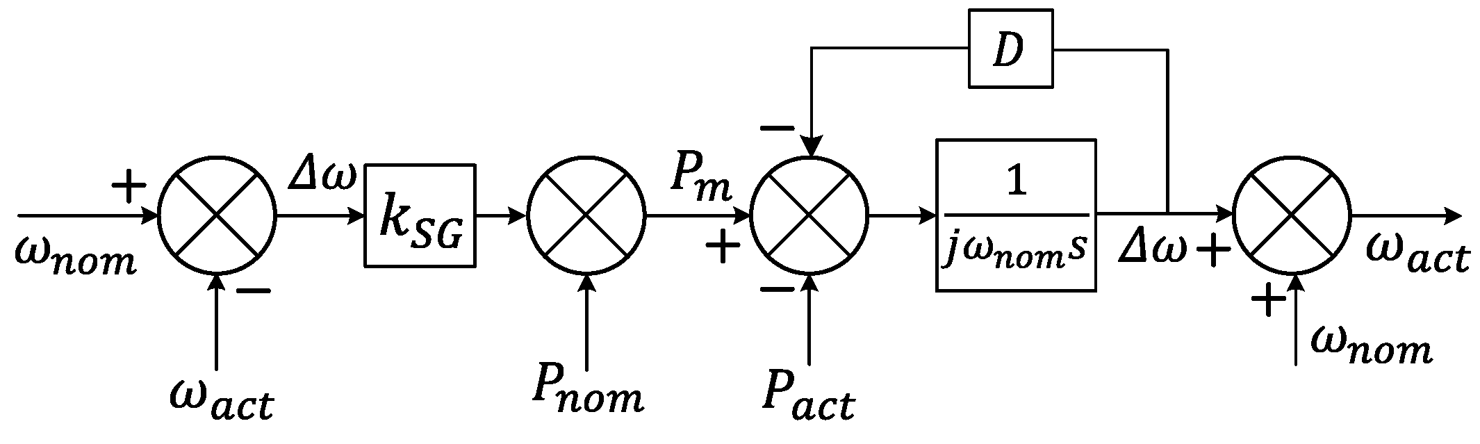
In the conventional SG-dominated grid, frequency control is achieved in three stages, known as primary, secondary and tertiary frequency controls [6,7,8]. The primary frequency controller (PFC) acts immediately after the occurrence of a disturbance and lasts for a few seconds. The purpose of PFC is to achieve the balance between power generation and demand after a disturbance. The droop-based controller is a widely accepted PFC in the conventional system. However, an inherent property of the droop controller is that it suffers from steady-state frequency deviation. Therefore, a secondary frequency controller (SFC) is required to regulate the frequency to the nominal value. The SFC is achieved by controlling the bias frequency of the SGs which lasts from a few seconds to minutes. The tertiary frequency control is implemented to minimize the total generation cost by optimizing the generation set-point of the SGs.
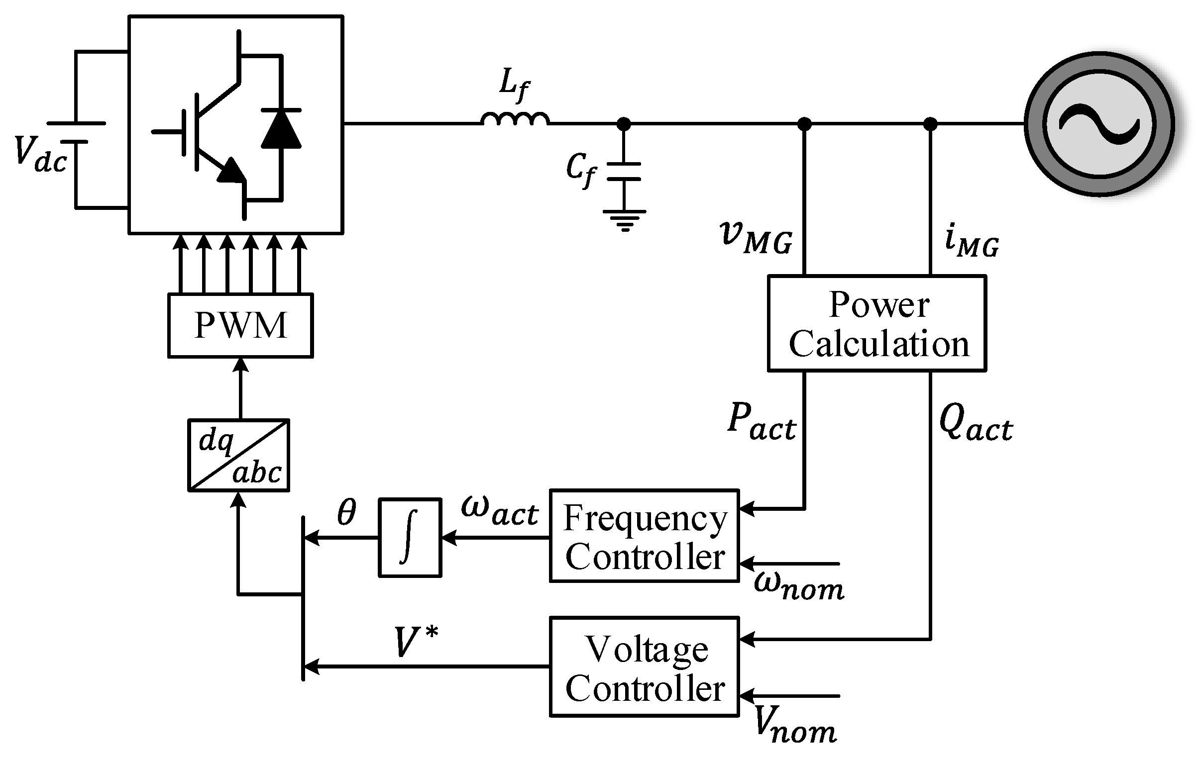
On the other hand, the PFC response of a microgrid is mainly governed by the control of inverters that interface the RES with the rest of the system. The grid-connected converters can be controlled in two modes, known as grid-forming mode and grid-following mode [9]. An inverter, in grid-forming mode, acts as a voltage source and is responsible for controlling the magnitude and frequency/phase of the voltage. In a microgrid with 100% inverter-based sources, at least one inverter must operate in grid-forming mode. In the grid-following mode of operation, the inverter is controlled as a current source and exchanges a fixed amount of active/reactive power with the rest of the microgrid. In the mixed-source microgrid, where SGs are already operated as grid-forming units, the inverters of the RES have the flexibility of being operated either in grid-forming or grid-following mode.
In the literature, both modes of operation are explored for PFC in microgrids. However, the grid-forming mode has gained more attention in recent years. Within this mode, the droop-based control [10] of a grid-connected inverter is a popular PFC method. However, in the absence of physical inertia, the frequency of the inverter changes suddenly with a change in its output power when operated with the conventional droop-based control. To address this issue, a variety of control methods with improvement of the conventional droop-based control have been proposed which are based on adaptively modifying the static droop coefficient of the conventional droop controller. For instance, [11] proposes an adaptive decentralized droop controller that combines an adaptive transient droop function with the conventional static droop characteristic, which improves the frequency and power-sharing stability. The PFC method presented in [12] adds a frequency derivative term to the power control loop of the conventional droop equation. Various other control techniques, such as neural network-based [13], fuzzy-based [14] and particle swarm optimization [15], to name a few, were also explored to adaptively modify the droop coefficient. To provide inertia to the system, a virtual synchronous generator (VSG) control was proposed in [16]. This method controls the frequency of a grid-connected inverter to mimic the characteristic of a droop-controlled SG. This method is also regarded as the generalized form of droop-based control with improved transient response [17]. However, the VSG controller also suffers from power and frequency oscillation during a disturbance. Similar to the droop controller, various control techniques are explored to improve the performance of the VSG controller [18,19,20,21,22,23]. These techniques are based on adaptively modifying the virtual inertia and damping provided by the grid-connected inverter.
So far, the grid-following mode of operation, also known as P-Q mode, is little explored for frequency control. Traditionally, this mode of operation has been used to interface non-dispatchable RES sources to the main grid that are controlled to operate at a fixed amount of power. However, this mode of operation can also be used for PFC if the output of power of the inverter is controlled to compensate for the power imbalance in the system. With the advancement in fast-acting switches, microcontrollers and fast-responding BESS, the output power of a BESS can be controlled in real time for fast PFC in the microgrid. In [24], the two modes of inverter operation are compared for PFC in an islanded microgrid and it is concluded that the performance of the grid-forming mode is better than the other one. However, in [24], the output power of the inverter is not controlled in real time when operated in the grid-following mode. The PFC method proposed in [25] implements a simple proportional–integral (PI) controller to control the output power of the BESS. The input to the PI controller is frequency deviation and the output is the reference power for the BESS. The issue with the implementation of the simple PI controller is that the variation in frequency is oscillatory with multiple harmonics. In such a condition, the reference power, hence the output power, of BESS also oscillates and the performance of the frequency controller is compromised.
This paper also implements a PI controller to determine the reference power of the BESSs. However, the proposed method first estimates the real-time power imbalance in an SG, which is then input to the PI controller to determine the reference power of the BESSs. The power imbalance in an SG is estimated using the initial RoCoF and the frequency-to-load transfer function (FLTF) of the SG. The salient features of the proposed PFC are as follows:
  • The proposed PFC fully compensates for the power imbalance in the microgrid without requiring communication among the BESSs.
  • The BESS controller requires the FLTF of only one SG to control its output power. Hence, the complexity of the proposed PFC does not increase with the increase in the number of BESSs and SGs.
  • The controller parameters of the BESSs can be selected such that the power compensated by the BESSs is proportional to their rating.
  • The proposed PFC does not require a secondary frequency controller (SFC), since there is no steady-state error.

2. Conventional Primary Frequency Control Methods

Figure 1 shows a grid-connected inverter with its control in grid-forming mode. In this mode, the inverter is operated as a voltage source and the control objective is to regulate the magnitude and frequency of the voltage at their nominal value. The droop and the VSG controllers are the most popular methods in this mode to control the voltage based on active and reactive power supplied by the inverter. Since the focus of this paper is frequency control, only the active power control loop is discussed in the remainder of this paper.

2.1. Droop Control

The block diagram of PFC using the droop-based control is shown in Figure 2. The frequency at which the grid-side converter is operated is given as
ω a c t = ω n o m + R P n o m P a c t
where ω a c t is the frequency at which the grid-side converter is operated, P a c t is the active power supplied by the by BESS, ω n o m is the nominal frequency, P n o m is the active power supplied by the BESS at the nominal frequency and R is the droop constant. As ω n o m and P n o m are constants, the change in frequency ( Δ ω ), as a function of the change in active power ( Δ P ) supplied by the BESS, can be expressed as
Δ ω = R Δ P
where Δ ω is the difference between nominal and actual frequency. In the event of a disturbance in the microgrid, the output power from the BESS changes instantly. Consequently, following Equation (2), the frequency of the BESS also changes as soon as the disturbance occurs in the microgrid. Therefore, the droop controller is known to provide negligible inertia to the system. To improve the frequency response of the grid-connected converter, a VSG control is proposed in [16], which is discussed in the next subsection.

2.2. Virtual Synchronous Generator Control

The VSG controller provides virtual inertia to the BESS/DG by emulating the characteristics of an SG. The block diagram for a PFC using the VSG controller is shown in Figure 3. The dynamics of frequency can be represented by the two following equations:
P n o m + ω n o m ω a c t k S G = P m
P m P a c t = D Δ ω + J ω n o m d Δ ω d t
Equation (3) represents the dynamics of the virtual speed governor.
where k S G is the proportional gain of virtual speed governor and P m is the virtual mechanical power. The virtual rotor dynamic is represented by Equation (4), where J and D are controller parameters, known as virtual inertia and damping constant, respectively. From Equation (4), at the steady state, the RoCoF is 0 and P m P a c t = D Δ ω . In the event of a disturbance, P a c t changes almost instantly, while the change in P m and Δ ω is relatively slow. Therefore, at the instant of disturbance, the RoCoF can be approximated, in terms of change in active power from BESS, as
d Δ ω d t = 1 J ω n o m Δ P
It can be observed, from Equation (5), that the initial RoCoF is inversely proportional to the virtual inertia which prevents the sudden change in frequency of the grid-side converter. Therefore, the VSG controller is known to provide inertia to the system.

3. Proposed PFC

3.1. Description of the Considered System for the Proposed PFC

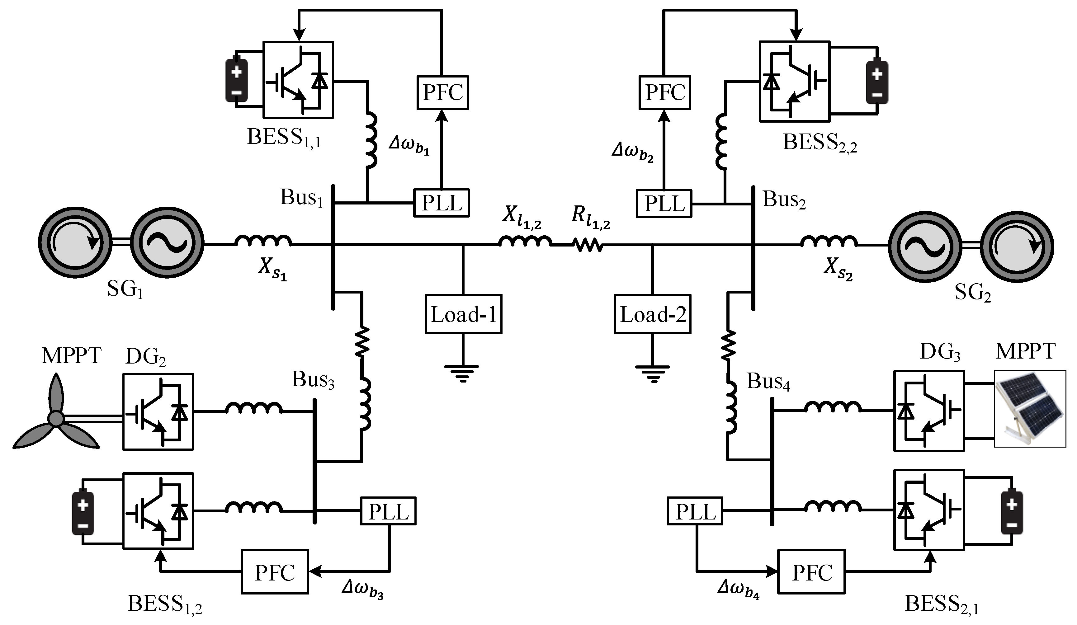
The microgrid configuration considered in this paper is comprised of multiple SGs, inverter-based RESs, BESSs and loads. An example of the considered system is shown in Figure 4, where two SG-based sources, one wind and one PV-based power sources and four BESSs are interconnected. In general, the considered system for the proposed PFC can have any number of BESSs placed anywhere in the microgrid. The PFC of each BESS uses the FLTF of the nearest SG to determine its reference power. It should be noted that the nearest SG does not imply a neighboring SG. In this paper, the nearest SG refers to the SG which accounts for the minimum line impedance from a BESS as compared to other SGs. In Figure 4, the BESSs are referred to as BESSi,j, where i represents the ith SG and j represents the jth BESS which uses the FLTF of the ith SG.
The SGs act as the grid-forming units and are operated in parallel with droop control. The inverters powered by wind and PV are represented as DGs. These DGs are operated in grid-following mode and controlled to extract the maximum power from the corresponding sources. Therefore, they are not considered to participate in frequency control. However, a change in output power from DGs affects the frequency of the system. In the considered system, the BESSs serve to provide frequency support in the event of a disturbance. The BESSs are also operated in grid-following mode. However, the output power of each BESS is controlled such that the addition of power supplied/absorbed by all the BESSs compensates for the power imbalance in the system in real time. The reference power of a BESS is determined using the change in frequency observed by the PLL and the FLTF of the nearest SG. It is assumed that the number of the BESSs may be more than that of SGs. Thus, the FLTF of one SG may be used by multiple BESS to determine their reference power.

3.2. FLTF of an SG and Estimation of Power Imbalance

The FLTF of the ith SG is expressed as
G i s = Δ ω i s Δ P D i s
where Δ ω i and Δ P D i are, respectively, the change in frequency and active power shared by the ith SG during a disturbance. The FLTF of an SG depends on various factors, such as rotor parameters, speed governor characteristics and droop coefficients. Based on these factors, the FLTF, as derived in [26], is given as
G i s = 1 + s t d ) / ω n o m + R i K i F s ( 1 s t d 1 s t d K i F s + J i s + D i 1 + s t d
where ω n o m is the nominal frequency, R i is the droop constant, K i F s is the speed governor characteristic, J i is the moment of inertia, D i is the damping constant and t d is the engine delay. Equation (7) is used to estimate the change in power supplied by the 
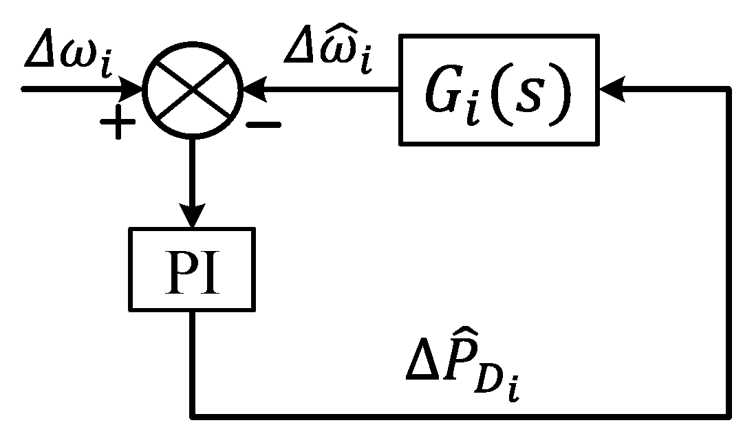
ith SG by observing the change in its bus frequency. The block diagram for the power estimation is shown in Figure 5. As shown in Figure 5, based on the initial guess of the power imbalance, an estimated value of the change in frequency ( Δ ω ^ i ) is evaluated using the FLTF derived in Equation (7). The estimated change in frequency is then compared with the actual change in frequency. Based on the error between the estimated and the actual value of frequency, the PI controller modifies the estimated change in power imbalance, Δ P ^ D i . The PI controller ensures that the estimated change in frequency equalizes the actual change in frequency, which leads to convergence of Δ P ^ D i towards Δ P D i .

3.3. Frequency Division

In general, the variation of frequency of the SGs is not synchronized during the transient. This also leads to a difference in the bus frequency and the rotor frequency of an SG. The relation between the two frequencies is given by the frequency division rule [27], based on which the change in frequency, at Bus-1 in Figure 4, is given as
Δ ω b 1 = Δ ω 1 R 12 + j X s 2 + X 12 + Δ ω 2 X s 1 R 12 + j X s 1 + X s 2 + X 12
where ω b i represents the frequency of the ith bus, X s 1 and X s 2 are the synchronous reactance of the SG1 and SG2, respectively, and R 12 and X 12 are the resistance and reactance of the line connecting SG1 and SG2. In general, the frequency variation at any point in the system depends on the frequency of all the sources/generators. However, in Equation (8), the frequency of the DGs is not included as they are operated in grid-following mode. Additionally, the inductive impedance dominates in Equation (8), as the reactance of the SGs is much higher than the resistance of the line. Therefore, Equation (8) can be simplified as
Δ ω b 1 = Δ ω 1 X s 2 + X 12 + Δ ω 2 X s 1 X s 1 + X s 2 + X 12
Similarly, the change in frequency at Bus-2 is given as
Δ ω b 2 = Δ ω 1 X s 2 + X s 1 + X 12 Δ ω 2 X s 1 + X s 2 + X 12
In the considered system, as Bus-3 is connected to only Bus-1 and Bus-4 is connected to only Bus-2, the following equations can be written:
Δ ω b 3 = Δ ω b 1
Δ ω b 4 = Δ ω b 2
Note that Equations (11) and (12) are valid only for the considered system of Figure 4. Nevertheless, for any system, the frequency of each bus can be obtained using the frequency division rule. The following subsection, without the loss of generality, uses Equations (11) and (12) to derive the expression of total power compensated by all the BESS and form the close loop structure of the proposed frequency controller.

3.4. Closed-Loop System for Power Imbalance Compensation

The closed-loop system of the proposed PFC is shown in Figure 6, where Δ P D represents the power imbalance caused by a change in load or change in the power output from the RESs. The compensating power supplied by the BESS is represented by P B E S S . The resulting closed loop power imbalance ( Δ P D c l ) is supplied by the SGs and causes asynchronous variation of frequency. The corresponding change in the bus frequency is given by Equations (9)–(12) and is observed by phase-locked loop (PLL) at the BESS. Based on the observed frequency, the BESSs estimate the change in power supplied by the nearest SG during a disturbance. Based on the estimated change in power supplied by the nearest SG, each BESS sets its reference power using a PI controller, which is given as
Δ P r e f i , j = k p i , j + k i i , j s Δ P ^ d i = k p i , j + k i i , j s Δ ω b i G i s
where Δ P r e f i , j represents the change in reference power and k p i , j and k i i , j are the constants of PI controller of the jth BESS which is the nearest to the ith SG. It is noted, from (13), that the reference power depends both on the frequency deviation and the constants of the PI controller. The constants of the PI controller of those BESSs, that use the FLTF of the same SG, are selected proportional to their power rating. Such a setting distributes the required compensated power based on the power rating of the BESS. Thus, choosing
k p i , j = Γ i , j k p i ,   k i i , j = Γ i , j k i i
where Γ i , j is the power rating of BESSi,j and k p i and k i i are constants for all the BESS using the FLTF of ith SG. In this paper, it is assumed that the BESS power controller is at least ten times faster than the power estimation loop which implies that the output power of the BESS follows its reference power. Therefore, using (13) and (14), the total power supplied by all the BESSs is given as
P B E S S s = Γ 1 , 1 Δ ω b 1 G 1 s + Γ 1 , 2 Δ ω b 3 G 1 s k p 1 + k i 1 s + Γ 2 , 1 Δ ω b 4 G 2 s + Γ 2 , 2 Δ ω b 2 G 2 s k p 2 + k i 2 s
Using   Δ ω b 3 = Δ ω b 1 from Equation (11) and Δ ω b 4 = Δ ω b 2 from Equation (12) in Equation (15),
P B E S S s = Γ 1 k p 1 + k i 1 s Δ ω b 1 G 1 s + Γ 2 k p 2 + k i 2 s Δ ω b 2 G 2 s
where Γ 1 = Γ 1 , 1 + Γ 1 , 2 and Γ 2 = Γ 2 , 1 + Γ 2 , 2 are the total power rating of the BESSs that use FLTF of SG1 and SG2, respectively. Using Equations (9) and (10) to express Equation (16) in terms of rotor frequency of the SGs
P B E S S s = Γ 1 k p 1 + k i 1 s Δ ω 1 X s 2 + X 12 + Δ ω 2 X s 1 X s 1 + X s 2 + X 12 1 G 1 s + Γ 2 k p 2 + k i 2 s Δ ω 1 X s 2 + X s 1 + X 12 Δ ω 2 X s 1 + X s 2 + X 12
Assuming the power rating of SG2 is η times that of SG1 and considering K and J are proportional to the SG rating in Equation (7), the relation between the FLTF of the two SGs can be approximated as
G 1 s = η G 2 s
considering that the per-unit value of the synchronous reactance of the SGs is typically the same with respect to their base. This implies that the actual value of the synchronous reactance is inversely proportional to the power rating of the SG, resulting in
X s 1 = η X s 2
Using Equations (18) and (19) in Equation (17),
P B E S S s = Γ 1 k p 1 + k i 1 s Δ ω 1 G 1 s + Γ 2 k p 2 + k i 2 s Δ ω 2 G 2 s
Expressing Δ ω 1 G 1 s = Δ P d 1 and Δ ω 1 G 1 s = Δ P d 1 , in Equation (20),
P B E S S s = Γ 1 k p 1 + k i 1 s Δ P d 1 + Γ 2 k p 2 + k i 2 s Δ P d 2
Equation (21) shows that the total power compensated by the BESSs, which uses the FLTF of an SG, is proportional to the change in power supplied by that SG during the transient. Additionally, the constants k p i and k i i can be selected such that
Γ 1 k p 1 + k i 1 s = Γ 2 k p 2 + k i 2 s = Γ k p + k i s
Applying Equation (22) in Equation (21),
P B E S S s = Γ k p + k i s Δ P d 1 + Δ P d 2 = Γ k p + k i s Δ P d c l
From Equation (23), it is noted that the total power supplied by all the BESS in the system is directly proportional to the closed-loop disturbance in the system. From Figure 6 and Equation (23), the closed-loop transfer function of power imbalance can be obtained as
Δ P d c l s Δ P D s = 1 1 + Γ k p + k i s
As k p , k i and Γ are positive constant, the closed-loop transfer function in Equation (24) is stable and guarantees zero power imbalance, hence zero frequency deviation, in the steady state.

3.5. Sensitivity Analysis

A sensitivity analysis is carried out to analyze the robustness of the proposed frequency controller as the system derived in Equation (24) may not be accurate for a practical system. The variation may occur due to the following non-idealities:
  • The presence of non-linearities in the frequency dynamics which are neglected in the derivation of the FLTF of SGs.
  • Presence of finite resistance of the transmission lines.
  • Finite bandwidth of PLL, power estimation loop and power control loop.
The above factors affect the estimation of the change in power supplied by SGs during a disturbance. Although the derivation of the closed-loop system, considering each one of the above factors separately, is beyond the scope of this paper, an aggregate of their effect can be analyzed by including an error term in the estimation of total power imbalance. Modifying Equation (24) to include the aggregated error in power imbalance estimation as
P ^ B E S S s = Γ k p + k i s 1 + ξ Δ P d c l
where ξ is the per-unit error in the estimation of total power imbalance and P ^ B E S S s is the actual power compensated by all the BESSs considering the error in the power estimation. Accordingly, the closed-loop transfer function is modified as
Δ P d c l s Δ P D s = 1 1 + Γ 1 + ξ k p + k i s
Applying the final value theorem to Equation (26), the steady-state power imbalance converges to zero if the stability of the system is guaranteed, which can be determined by analyzing the pole of the transfer function in Equation (26). From Equation (26), the pole is obtained as
s = Γ 1 + ξ k i 1 + Γ 1 + ξ k p
It is observed, from Equation (27), that the pole of Equation (26) is negative if ξ > 1 for any value of positive k p and k i . Note that a very high value of the PI controller parameter may destabilize the system due various factors, such as PLL dynamics, finite control bandwidth of power estimation power controller loops, the time constant of the two loops, etc. Moreover, a further addition of BESSs may equivalently increase k p and k i . However, finding out the exact range of k p and k i for stable operation is considered for future work and is not in the scope of this paper.

4. Model Description for Case Study

To verify the efficacy of the proposed method, real-time simulations were performed on the Typhoon Hardware-in-the-loop simulator. The system for the case study was modeled similar to the considered system shown in Figure 4. The model consisted of two SGs, two DGs, three BESSs and two loads. The SGs were termed as SG1 and SG2 and their rating was 550 KVA and 1.1 MVA, respectively. The power rating of both the DGs was selected as 500 kW. Practically, the microgrid consisted of a higher number of DGs, each with a lower power rating. However, due to the limitation of the size of the model in the Typhoon simulator, the combined effect of all the DGs was modeled as only two DG for the case study.
The total active power demand in the microgrid was realized by two equivalent loads: Load-1 as 1.5 MW and Load-2 as 500 kW. The equivalent Load-1 represented the loads with constant power demand, while the varying loads were modelled as the equivalent Load-2. Although the total number of the BESSs is four, in Figure 4, the simulation model used only three BESSs (BESS1,1, BESS1,2 and BESS2,1) due to the limitation on the size of the model in the Typhoon real-time simulator. The model of each BESS consisted of a battery pack and a three-phase inverter that interfaced the battery pack with the microgrid as shown in Figure 4. The model of the battery pack was a voltage source in series with internal resistance. The nominal voltage of each battery pack was selected as 240 V. The nominal capacity of BESS1,1 was 100 Ah and that of BESS1,2 and BESS2,1 was 200 Ah each. The nominal continuous charge/discharge current was 1 C, while the peak charge/discharge current was 5 C. Other relevant simulation parameters of the microgrid are provided in Table 1.

5. Real-Time Simulation Results

5.1. Frequency Control with VSG-Based PFC

First, the simulation was performed using the conventional VSG-based control method for the case of sudden addition of the constant impedance load. To start the simulation, Load-1 of 1.5 MW was connected to the microgrid and the output power of the two DGs was set to 500 kW each. Therefore, before the addition of the Load-2, which was the constant impedance load of 500 kW at the nominal voltage, the total power shared by the SGs and BESS was 500 kW. The performance of the VSG-based PFC during the sudden addition of Load-2 is shown in Figure 7. The variation in the frequency of the two SGs and the three BESSs are shown in Figure 7a,b, respectively. As the BESS was operated in the grid-forming mode, the frequency of SGs and the frequency at which the BESSs were operated were different during the transient. The peak frequency deviation for the SG2 and BESS1,2 were observed as 0.60 Hz and 0.65 Hz, respectively. The steady-state change in frequency for both SGs and BESSs was observed as 0.28 Hz.
The variation of active power supplied by the SGs and BESSs during the transient of addition of Load-2 are shown in Figure 7c,d, respectively. Among other factors, the amount of active power supplied by the SGs and BESSs during the transient also depends on droop constants and inertia/virtual inertia of the SGs/BESSs. In general, a higher amount of inertia results in a lower amount of peak frequency deviation. While the inertia of the SGs is fixed, the virtual inertia of BESSs can be selected to any value. However, selecting a very high value of virtual inertia leads to a higher amount of power shared by BESS which may exceed the power rating of the BESS. The amount of power shared and the change in frequency in the steady state depends only on the droop constants of the sources. The droop constants and inertia/virtual inertia of the sources for the simulation are provided in Table 1. The droop constants were selected inversely proportional to the rating of the SGs/BESS. Therefore, as observed in Figure 7d, the steady-state power shared by BESS1,1 was nearly half of the power shared by BESS1,2. As the VSG-based PFC suffers from steady-state frequency deviation, an SFC is required to regulate the frequency to the nominal value. However, the SFC was not implemented in the simulation as the focus was to compare the PFC of the VSG and the proposed control.

5.2. Frequency Response with Proposed Frequency Controller

For the implementation of the proposed PFC, the inverter of the BESS was operated in grid-following mode. In this mode, the grid-side inverter of all the BESSs was operated in power-control mode and the frequency of the inverter was controlled to be the same as the frequency of the microgrid. The active power supplied by the BESSs was controlled to compensate for the estimated power supplied by the nearest SG during the transient. The reference power of BESS1,1, BESS1,2 and BESS2,1 was determined using the estimated power supplied by SG1, SG1 and SG2, respectively. BESS2,2 could not be accommodated in the simulation model due to the limitation on the size of the model. As the proposed work is focused on frequency control, the reactive power supplied by the BESS was regulated to be zero. The simulations implementing the proposed PFC were performed for a sudden change in constant impedance load and dynamic change in power output from DGs, which are discussed below.
  • Sudden change in constant impedance load
The simulation implementing the proposed PFC for a sudden change in constant impedance load was performed under the same loading condition as for the VSG controller. Figure 8a shows the variation of frequency with the active power compensated by the BESSs during the sudden addition of Load-2. In Figure 8b, the variation in frequency is shown with the active power supplied by the SGs. It is observed, from Figure 8a, that the BESSs supplied approximately 450 kW as soon as the Load-2 was connected, which was rated for 500 kW at the nominal voltage. Due to the voltage drop in the line, the active power absorbed by the equivalent Load-2 was 450 kW, which was less than its rating. Irrespective of the voltage drop in the line, the total power imbalance was estimated and compensated based on the actual power delivered to Load-2. This is evident from Figure 8b, which shows that the power supplied by the SGs during transient was negligible. The parameters of the PI controller of the BESSs were selected according to Equation (14).
Therefore, BESS1,1, which had a lower rating BESS, supplied a proportionally lower amount of power than the other two BESSs. Since the BESS was operated in grid-following mode, the frequency of the BESS did not drop as a result of the power compensation. Therefore, a lower amount of frequency deviation of 0.05 Hz was observed during the transient. Additionally, there was no steady error in the frequency. Therefore, the proposed controller does not require SFC.
  • Dynamic change in DG output power
To validate the proposed PFC for the case of dynamic disturbance, all the loads remained connected to the microgrid while the output power of DG1 was varied by controlling its grid-side converter. The resulting change in output power from the DG and the variation in frequency are shown in Figure 9a. The waveform of the compensating power supplied by the BESSs with the change in output power from the DG is shown in Figure 9b. As shown in Figure 9, the proposed method was tested for the maximum change of 500 kW, as well as for smaller changes in output power from the DG1. It can be observed that the BESSs fully compensated for the power imbalance in each step within the millisecond range. For the maximum change of 500 kW, the peak frequency deviation was noted as 0.06 Hz. The frequency deviation for smaller changes in DG output power was proportionally smaller, as shown in Figure 9a.
The performance of the proposed method was also verified for the case when the total BESS capacity is less than the maximum power imbalance. For this case, the BESS2,1 was disconnected from the system and the total BESS capacity was limited to 360 kW (BESS1,1, 120 kW; BESS1,2, 240 kW). The corresponding results for change in output power from the DG are shown in Figure 10. The simulation was started when the DG was supplying 500 kW and the BESSs were absorbing power based on their current SoC. When the output power DG was set to 0, the output power of the BESSs hit their total maximum limit of 360, since the power imbalance was 500 kW. The remaining power was supplied by the SGs. Therefore, a frequency deviation of 0.25 Hz and 0.07 Hz were observed during the transient and steady state, respectively.

6. Conclusions

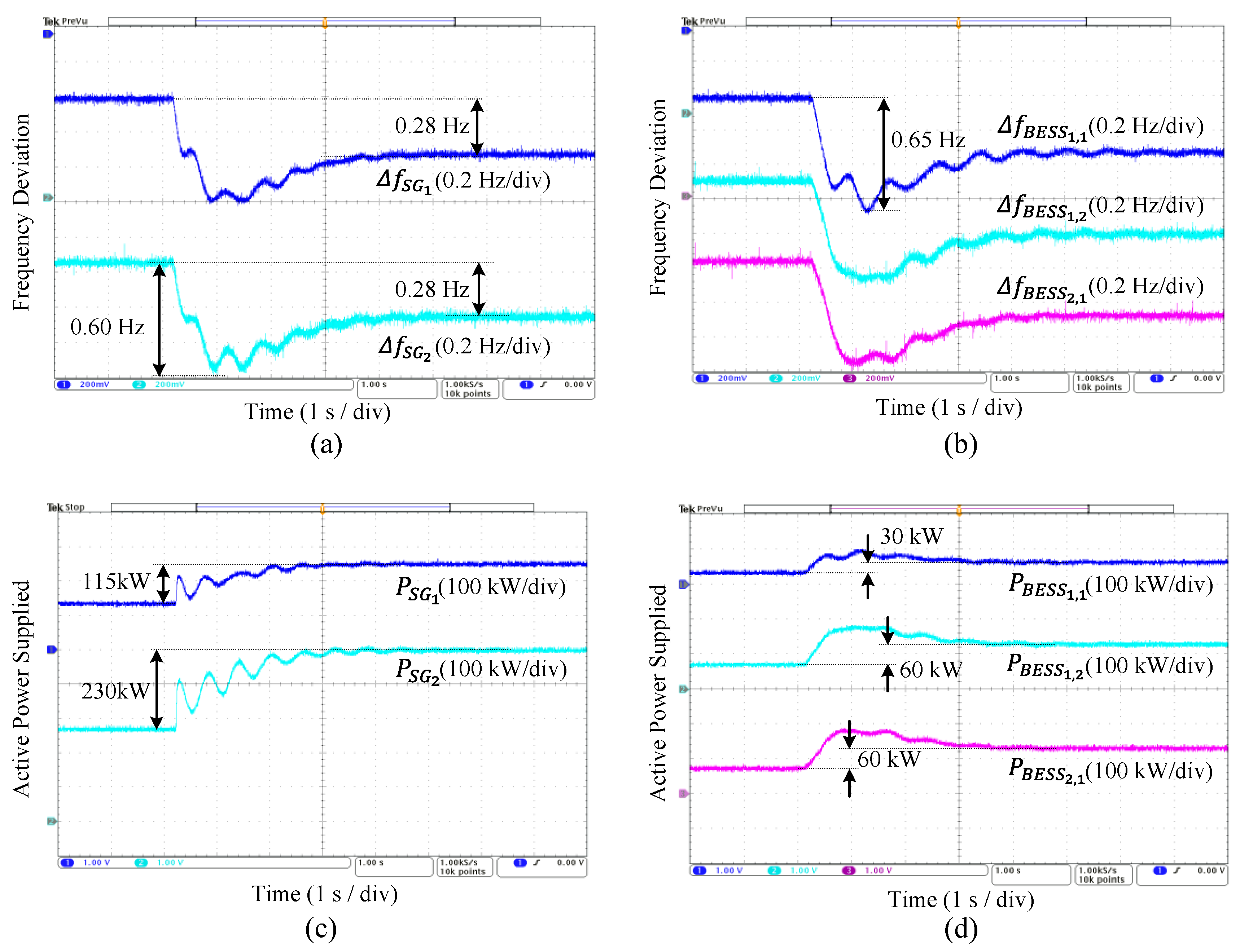
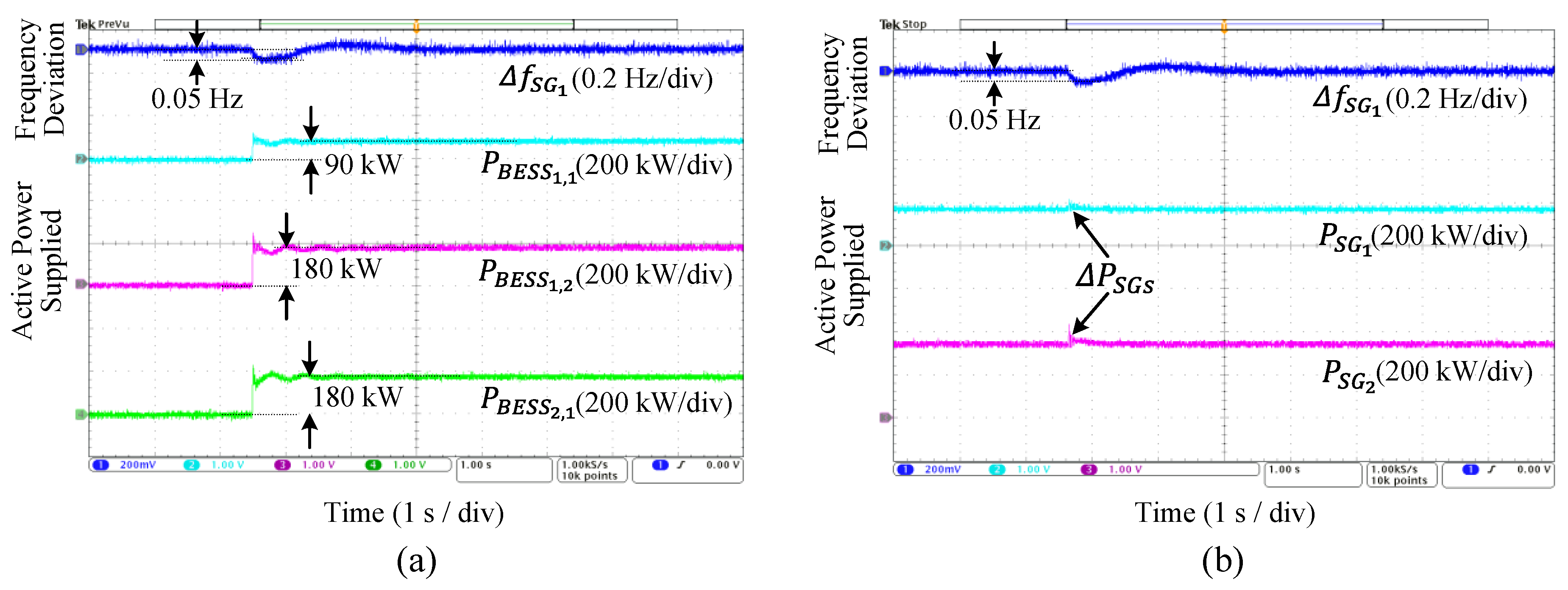
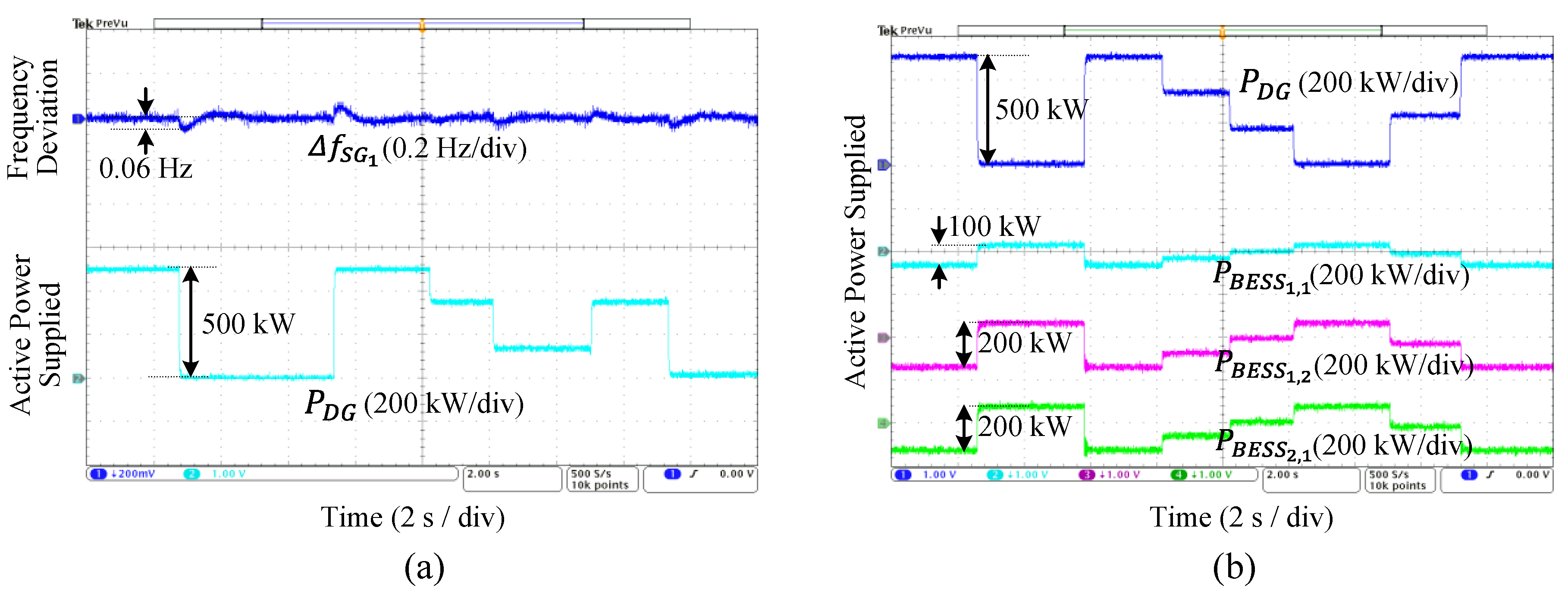
This paper presents a fast frequency control method for an islanded microgrid using multiple small-scale BESSs. The proposed PFC is based on estimating the power imbalance during the transient and compensating it using multiple small-scale BESSs. The performance of the proposed controller is compared with that of the conventional VSG-based controller for a sudden change in constant impedance load, which was rated as 500 kW at nominal voltage. Using the proposed frequency controller, the peak frequency deviation was limited to 0.06 Hz, which was observed as 0.65 Hz, using the conventional VSG-based controller. Additionally, the proposed frequency controller does not require SFC as the steady-state error in the frequency is zero. However, the total power rating of the BESSs must be more than the maximum possible disturbance in the system to achieve zero steady-state error. If not, the simulation result shows that the remaining amount of power is supplied by the SGs, which results in steady-state frequency deviation. Still, the frequency deviation using the proposed method is less than that of the VSG controller, as the proposed method utilizes the full capacity of the BESSs. Therefore, it is concluded that the frequency response of the proposed controller is better than the VSG controller in terms of speed and steady-state error and can be achieved at the cost of a higher total power rating and a more frequent charging–discharging of the BESSs.

Author Contributions

Conceptualization, A.H. and W.S.; methodology, A.H.; software, A.H.; validation, A.H.; investigation, A.H. and W.S.; resources, A.H. and W.S.; data curation, A.H; writing—original draft preparation, A.H.; writing—review and editing, A.H. and W.S.; visualization, A.H.; supervision, W.S. All authors have read and agreed to the published version of the manuscript.

Funding

This research received no external funding.

Conflicts of Interest

The authors declare no conflict of interest.

References

  1. Katiraei, F.; Iravani, M. Power Management Strategies for a Microgrid With Multiple Distributed Generation Units. IEEE Trans. Power Syst. 2006, 21, 1821–1831. [Google Scholar] [CrossRef]
  2. Lasseter, R.H.; Eto, J.H.; Schenkman, B.; Stevens, J.; Vollkommer, H.; Klapp, D.; Linton, E.; Hurtado, H.; Roy, J. CERTS microgrid laboratory testbed. IEEE Trans. Power Del. 2011, 26, 325–332. [Google Scholar] [CrossRef] [Green Version]
  3. Russian, J.; Hussain, A.; Shireen, W. Power System Frequency Dynamics and challenges in achieving a 100% renewable grid. In Proceedings of the 2020 IEEE/PES Transmission and Distribution Conference and Exposition (T&D), Chicago, IL, USA, 12–15 October 2020; pp. 1–5. [Google Scholar] [CrossRef]
  4. Pazmiño, I.; Martinez, S.; Ochoa, D. Analysis of Control Strategies Based on Virtual Inertia for the Improvement of Frequency Stability in an Islanded Grid with Wind Generators and Battery Energy Storage Systems. Energies 2021, 14, 698. [Google Scholar] [CrossRef]
  5. Martínez-Lucas, G.; Sarasúa, J.I.; Sánchez-Fernández, J. Frequency Regulation of a Hybrid Wind–Hydro Power Plant in an Isolated Power System. Energies 2018, 11, 239. [Google Scholar] [CrossRef] [Green Version]
  6. Guerrero, J.; Vasquez, J.C.; Matas, J.; de Vicuña, L.G.; Castilla, M. Hierarchical Control of Droop-Controlled AC and DC Microgrids—A General Approach Toward Standardization. IEEE Trans. Ind. Electron. 2010, 58, 158–172. [Google Scholar] [CrossRef]
  7. Jin, C.; Wang, P.; Xiao, J.; Tang, Y.; Choo, F.H. Implementation of Hierarchical Control in DC Microgrids. IEEE Trans. Ind. Electron. 2013, 61, 4032–4042. [Google Scholar] [CrossRef]
  8. Seyedi, Y.; Karimi, H.; Grijalva, S. Distributed Generation Monitoring for Hierarchical Control Applications in Smart Microgrids. IEEE Trans. Power Syst. 2016, 32, 2305–2314. [Google Scholar] [CrossRef]
  9. Rocabert, J.; Luna, A.; Blaabjerg, F.; Rodriguez, P. Control of Power Converters in AC Microgrids. IEEE Trans. Power Electron. 2012, 27, 4734–4749. [Google Scholar] [CrossRef]
  10. Lopes, J.A.P.; Moreira, C.; Madureira, A. Defining Control Strategies for MicroGrids Islanded Operation. IEEE Trans. Power Syst. 2006, 21, 916–924. [Google Scholar] [CrossRef] [Green Version]
  11. Mohamed, Y.A.R.I.; El-Saadany, E.F. Adaptive decentralized droop controller to preserve power sharing stability of paralleled inverters in distributed generation microgrids. IEEE Trans. Power Electron. 2008, 23, 2806–2816. [Google Scholar] [CrossRef]
  12. Soni, N.; Doolla, S.; Chandorkar, M.C. Improvement of Transient Response in Microgrids Using Virtual Inertia. IEEE Trans. Power Deliv. 2013, 28, 1830–1838. [Google Scholar] [CrossRef]
  13. Chien, T.-H.; Huang, Y.-C.; Hsu, Y.-Y. Neural Network-Based Supplementary Frequency Controller for a DFIG Wind Farm. Energies 2020, 13, 5320. [Google Scholar] [CrossRef]
  14. Bevrani, H.; Shokoohi, S. An Intelligent Droop Control for Simultaneous Voltage and Frequency Regulation in Islanded Microgrids. IEEE Trans. Smart Grid 2013, 4, 1505–1513. [Google Scholar] [CrossRef]
  15. Yu, K.; Ai, Q.; Wang, S.; Ni, J.; Lv, T. Analysis and Optimization of Droop Controller for Microgrid System Based on Small-Signal Dynamic Model. IEEE Trans. Smart Grid 2015, 7, 695–705. [Google Scholar] [CrossRef]
  16. Beck, H.-P.; Hesse, R. ‘Virtual synchronous machine. In Proceedings of the 9th International Conference on Electrical Power Quality and Utilisation, Barcelona, Spain, 9–11 October 2007; pp. 1–6. [Google Scholar]
  17. Meng, X.; Liu, J.; Liu, Z. A Generalized Droop Control for Grid-Supporting Inverter Based on Comparison Between Traditional Droop Control and Virtual Synchronous Generator Control. IEEE Trans. Power Electron. 2018, 34, 5416–5438. [Google Scholar] [CrossRef]
  18. Alipoor, J.; Miura, Y.; Ise, T. Power System Stabilization UsingVirtual Synchronous Generator with Alternating. Moment of Inertia. IEEE Trans. Emerg. Sel. Top. Power Electron. 2015, 3, 451–458. [Google Scholar] [CrossRef]
  19. Torres, M.A.L.; Lopes, L.A.C.; Morán, L.A.; Espinoza, J.R. Self-Tuning Virtual Synchronous Machine: A Control Strategy for Energy Storage Systems to Support Dynamic Frequency Control. IEEE Trans. Energy Convers. 2014, 29, 833–840. [Google Scholar] [CrossRef]
  20. Alipoor, J.; Miura, Y.; Ise, T. Stability Assessment and Optimization Methods for Microgrid With Multiple VSG Units. IEEE Trans. Smart Grid 2016, 9, 1462–1471. [Google Scholar] [CrossRef]
  21. Li, D.; Zhu, Q.; Lin, S.; Bian, X.Y. A Self-Adaptive Inertia and Damping Combination Control of VSG to Support Frequency Stability. IEEE Trans. Energy Convers. 2016, 32, 397–398. [Google Scholar] [CrossRef]
  22. Wang, F.; Zhang, L.; Feng, X.; Guo, H. An Adaptive Control Strategy for Virtual Synchronous Generator. IEEE Trans. Ind. Appl. 2018, 54, 5124–5133. [Google Scholar] [CrossRef]
  23. Shi, K.; Chen, C.; Sun, Y.; Xu, P.; Yang, Y.; Blaabjerg, F. Rotor inertia adaptive control and inertia matching strategy based on parallel virtual synchronous generators system. IET Gener. Transm. Distrib. 2020, 14, 1854–1861. [Google Scholar] [CrossRef]
  24. Renjit, A.A.; Mondal, A.; Illindala, M.S.; Khalsa, A.S. Analytical Methods for Characterizing Frequency Dynamics in Islanded Microgrids With Gensets and Energy Storage. IEEE Trans. Ind. Appl. 2017, 53, 1815–1823. [Google Scholar] [CrossRef]
  25. Maneesh. Frequency control of a microgrid by using PI controller. In Proceedings of the IEEE 2015 International Conference on Energy, Power and Environment: Towards Sustainable Growth (ICEPE), Shillong, India, 12–13 June 2015; pp. 1–5. [Google Scholar]
  26. Hussain, A.; Shireen, W. Model for Frequency Dynamics in an Islanded Microgrid and Primary Frequency Control Based on Disturbance Compensation. IEEE Access 2021, 9, 52784–52795. [Google Scholar] [CrossRef]
  27. Milano, F.; Ortega, A. Frequency Divider. IEEE Trans. Power Syst. 2017, 33, 4414–4423. [Google Scholar]
Figure 1. Control structure of DG/BESS using droop and VSG controls.
Energies 14 07710 g001
Figure 2. Primary frequency control using droop controller.
Energies 14 07710 g002
Figure 3. Primary frequency control using VSG controller.
Energies 14 07710 g003
Figure 4. Schematic of the considered microgrid.
Energies 14 07710 g004
Figure 5. Power imbalance estimation of a synchronous generator using FLTF.
Energies 14 07710 g005
Figure 6. Closed-loop system representation of the proposed frequency control method.
Energies 14 07710 g006
Figure 7. Response of VSG-based PFC for sudden addition of the constant impedance load: (a) frequency of synchronous generators; (b) frequency of BESSs; (c) power supplied by SGs; (d) power supplied by BESSs.
Energies 14 07710 g007
Figure 8. Response of the proposed frequency controller for sudden addition of the constant impedance load: (a) Frequency variation of SG1 and power supplied by the BESSs, (b). Frequency of SG1 and power supplied by SG1 and SG2.
Energies 14 07710 g008
Figure 9. Response of the proposed frequency controller for dynamic change in output power from distributed generators: (a) frequency of SG1 and the variation in power from distributed generators; (b) variation in power from distributed generators and power supplied by the BESSs.
Energies 14 07710 g009
Figure 10. Response of the proposed frequency controller for dynamic change in output power from distributed generators when the total BESS capacity is less the power imbalance.
Energies 14 07710 g010
Table 1. Parameters of the microgrid.
DescriptionSymbol/Value
Nominal Frequency f n o m = 60   Hz
SG Nominal Voltage V n o m = 480   V   l   l
SG VA RatingSG1: 550   kVA ,   SG2: 1.1   MVA
SG Moment of Inertia J 1 = 62   kg   m 2 , J 2 = 124   kg   m 2
VSG Moment of Inertia J B E S S 1 , 1 = J B E S S 1 , 2 = J B E S S 2 , 1 = 62   kg   m 2
SG Droop Constant R 1 = 3   Hz / MW ,   R 2 = 1.5   Hz / MW
VSG Droop Constant R BESS 1 , 1 = 12   Hz / MW
R BESS 1 , 2 = R BESS 2 , 1 = 6   Hz / MW
SG Damping Coefficient D 1 = D 2 = 0.57   Nms
SG Stator Parameter R s 1 = 3.6   m , R s 2 = 1.8   m
L s 1 = 1   mH , L s 2 = 0.5   mH
Line Inductance between Buses L l 1 , 2 = L l 1 , 3 = L l 2 , 4 = 0.1   mH
Line Resistance between Buses R l 1 , 2 = R l 1 , 3 = R l 2 , 4 = 5   m
Load and DG RatingLoad-1: 1.5   MW , Load-2: 0.5   MW
DG1: 0.5 MW, DG2: 0.5 MW
Speed Governor Gain K 1 = 5 ,   K 2 = 10
Speed Governor Time T 1 = 0.5   s ,   T 2 = 100   us ,
Constants T 3 = 10 4   us ,
(Same for SG1 and SG2) T 4 = 25   ms ,   T 5 = 1   ms ,
SG Engine Delay t d = 24   ms ,
Battery RatingΓ1,1 = 120 kW, Γ1,2 = Γ2,1 = 240 kW
Power Controller
Constants
k p 1 = k p 2 = 11.5 × 10 8
k i 1 = k i 2 = 11.5 × 10 7
BandwidthLoad Estimation: 500 Hz BESS Power Controller: 5k Hz
Publisher’s Note: MDPI stays neutral with regard to jurisdictional claims in published maps and institutional affiliations.

